

Page 1
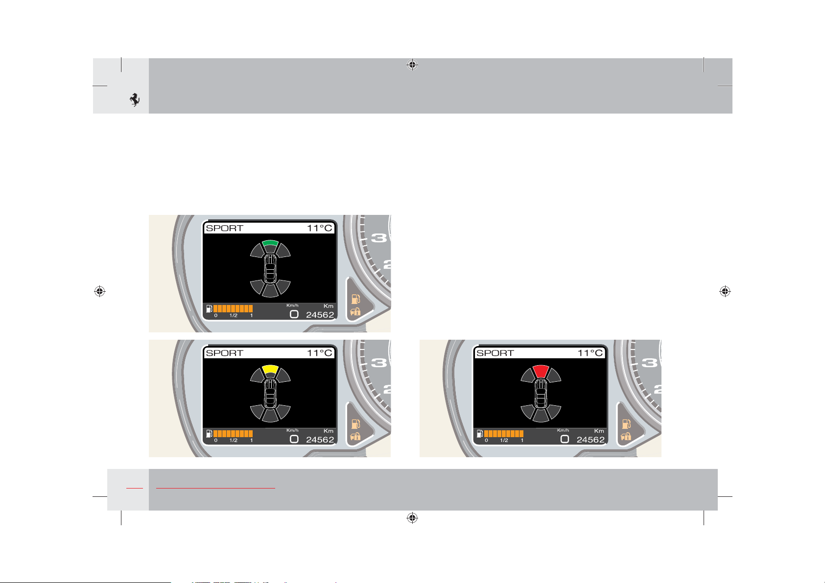
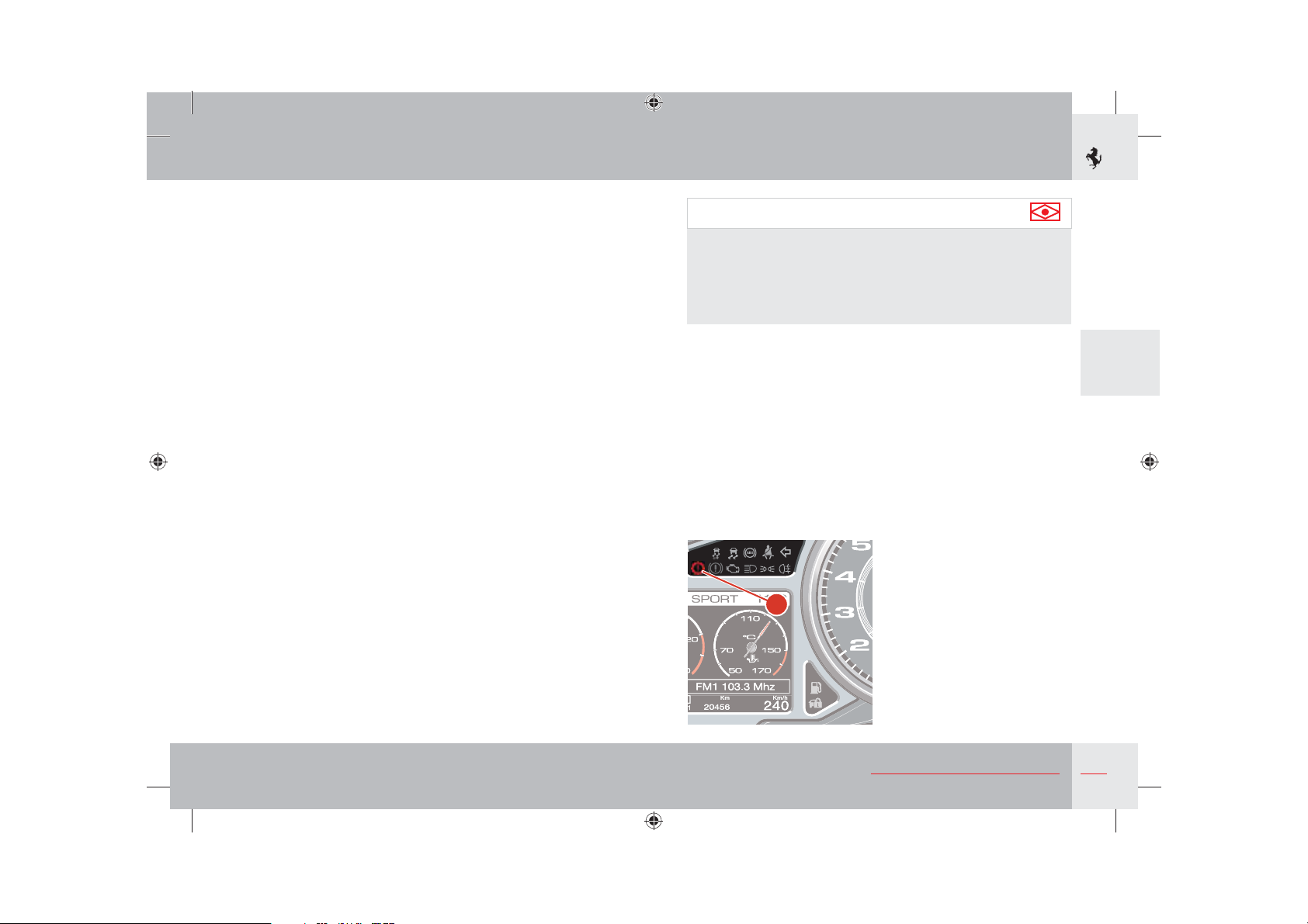
The vehicle symbol and sensor detection zones appear on the
TFT display: these zones indicate which part of the vehicle is
approaching an obstacle (if front or rear and if left, right or
central) and the distance from the obstacle (maximum, medium or
minimum).
If an obstacle is detected at maximum distance in the central front
part, it will be displayed as shown below (green).
If an obstacle is detected at medium distance in the central front
part, it will be displayed as shown below (orange).
If an obstacle is detected at minimum distance in the central front
part, it will be displayed as shown below (red).
142
About your Vehicle
Page 2
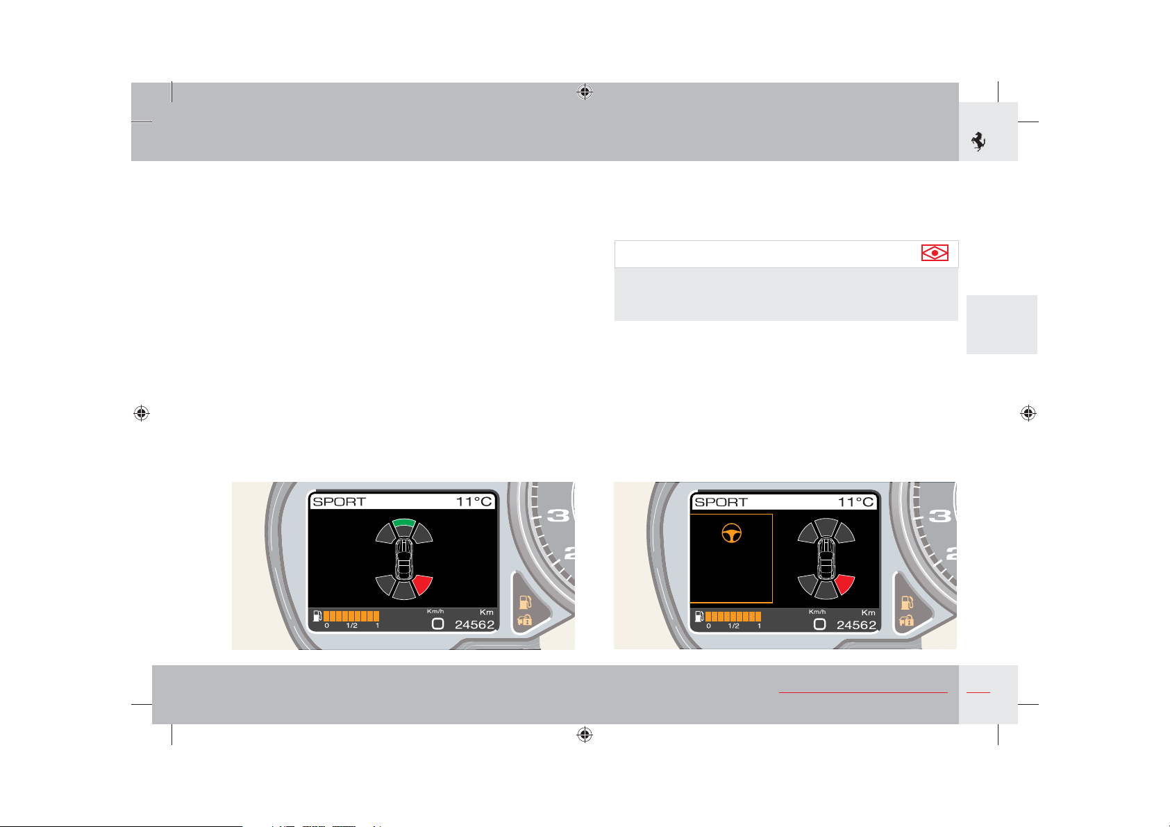
If the front sensors are deactivated or not present, the display does
not show the symbols in the front. In the same way, if front sensors
are fitted and the rear ones are not activated, the display only
shows the symbols in the front. If all the sensors are activated, the
system can give several pieces of information at the same time: if
an obstacle is detected at a maximum distance in the front central
part and at a minimum distance in the rear right part, it will be
displayed as shown below.
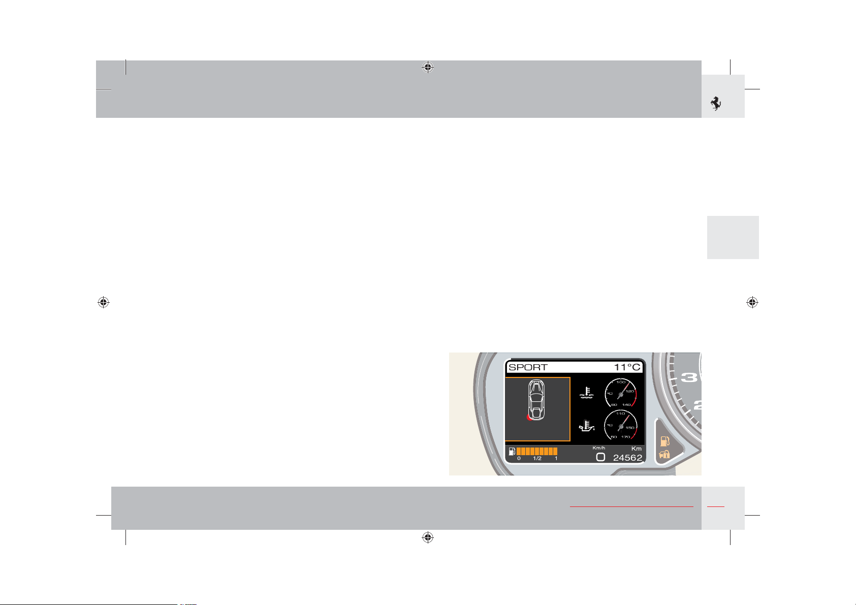
If the parking sensor system symbols are being displayed and an
event occurs that needs to be displayed as an icon and/or special
message, the symbol is moved from the centre of the display to the
right as shown below.
Important note
If there is a higher priority failure such as a tyre puncture, the
TFT display will indicate this failure and the parking sensor
symbols will disappear.
3
Once the failure has been displayed, the parking sensor symbols
will go back to the centre of the display.
About your Vehicle
143
Page 3
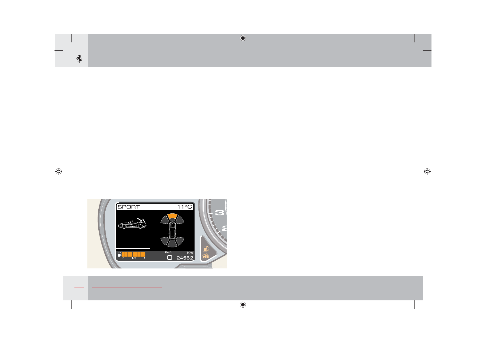
Simultaneous display of parking sensors and other systems
If other systems are activated when the parking sensors are being
displayed, the TFT display displays the sensors on the right of the
screen and the other active system on the left.
If the hard top is operated, the parking sensor display is deactivated
as the sensors will be detecting obstacles that may damage the
luggage compartment.
Cleaning the sensors
When cleaning the sensors, be very careful not to scratch or
damage them and avoid using dry, rough or hard cloths.
The sensors must be washed with clean water and car shampoo
added if necessary.
In car washes that use steam jet or high pressure water cleaning
equipment, quickly clean the sensors keeping the nozzle at a
distance of over 10 cm.
pe
For the repainting of bumpers or retouching the paintwork in
the sensor area, contact the Ferrari Service Network. If paint
is applied incorrectly, it may jeopardise proper operation of the
parking sensors.
Sensing range
The sensors allow the system to control the rear and front of the
vehicle: their position covers the central and side areas of the
vehicle.
If an obstacle is in the central area, it is detected at distances of
approximately 1.40 m depending on the type of obstacle and its
size.
If an obstacle is in the side area, it is detected at distances of less
than 0.8 m.
Failure signals
The system ECU checks all the components each time the reverse
gear is engaged.
A parking sensor system failure is indicated on the TFT display.
If there is a failure signal, stop the vehicle and turn the ignition key
to position 0 (Stop). Then try and clean the sensors or move them
away from any sources of ultrasound emissions (e.g. pneumatic
brakes of lorries or pneumatic drills) and turn the ignition key to
position II again. In this way, if the cause of malfunctioning has
been corrected, the system will start operating correctly again and
the failure buzzer will stop.
If the failure buzzer continues, contact the Ferrari Service
Network to have the system checked.
144
About your Vehicle
Page 4
Important note
Obstacles that may damage the luggage compartment (obstacles
at distances of less than 400 mm, see page 123) are detected
only once by the rear sensors prior to hydraulic operation of the
hard top. Any obstacles that appear after hard top activation will
not be detected.
Important note
The signals sent by the sensors may also be affected by damage
to the sensors caused by dirt, snow or ice on the sensors or
by ultrasound systems (e.g.. pneumatic brakes on lorries or
pneumatic drills) in the vicinity.
Important note
The sensors are able to detect obstacles with reasonably large,
even surfaces (e.g.: poles with diameters of over 60 mm, walls,
barriers, trees). Detection is not optimum with obstacles with
sharp projections or uneven surfaces.
Important note
When parking and operating the retractable hard top, always be
very careful to avoid obstacles that may be above or below the
sensors.
Important note
Objects placed close to the rear part of the vehicle are not
always detected by the system and may therefore damage the
vehicle or be damaged themselves.
Warning
However, the driver has full responsibility for parking
manoeuvres and in other potentially dangerous situations.
The system has been designed only as an aid during parking
manoeuvres and the operation of the retractable hard top,
since it detects obstacles that are outside the driver's range of
visibility.
The sensors are therefore not a substitute for the driver's care
and attention when parking and checking for the presence of
persons or objects.
About your Vehicle
3
145
Page 5
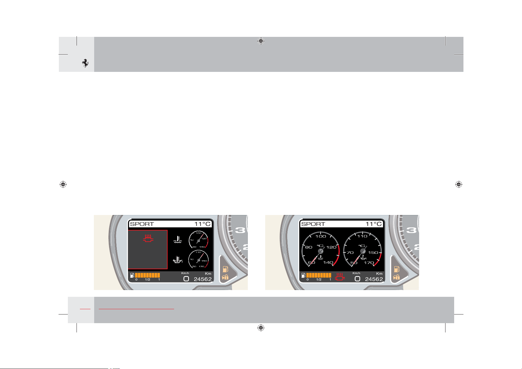
Fault display
Fault visualisation logic
When a fault occurs, the corresponding warning light (if present)
comes on on the panel whereas a description of the fault (if
available) and the relevant symbol (if available) are displayed on
the left TFT display. The message appears on the display as soon as
the warning light (if present) comes on and the main screen page
that is displayed at that time is reduced.
The fault remains on the display for 20 seconds. When the display
cycle ends, if the fault does not have a special warning light on the
panel, the symbol remains minimised in area
page 131) until the cause of malfunctioning has been resolved. In
area B the main screen page is displayed in “maximum” size.
&DWDO\VWVWHPS
WRRKLJK
(QJLQH
SHUIRUPDQFH
OLPLWHG
D of the display (see
When the display cycle ends, if the fault has a special warning light
on the panel, the screen page prior to the anomaly is displayed
again, and the symbol is not minimised in area
light on the panel stays on until the cause of malfunctioning has
been resolved.
If the fault is resolved within 20 seconds, it remains displayed and
the warning light remains lit for 2 seconds.
“ESCAPE” function
Displaying a fault on the screen can be interrupted by pressing and
quickly releasing the OK button with “ESCAPE” function. When
the OK button is pressed, the screen page that was displayed prior
to the event reappears. If the fault does not have a special warning
light on the panel, the symbol remains minimised in area
the cause of malfunctioning has been resolved.
D. The warning
D until
146
About your Vehicle
Page 6
Fault priority levels
The simultaneous display of several faults follows a logic that
depends on the priority level assigned to it.
Priority level 0 - Extremely critical fault.
Priority level 1 - Critical fault.
Priority level 2 - Non-critical fault.
When several fault events occur at the same time, faults with
priority level 0 are displayed first, followed by priority level 1
and then priority level 2. The information on the various faults is
displayed in turn for 5 seconds each. In any case, the total display
time for each fault is never less than 20 seconds.
If a fault message with priority level 1 or 2 is being displayed, and
a new anomaly with the same priority level occurs, the last fault
message is only displayed after the first fault message has been
displayed for at least 2 seconds. If, on the other hand, another new
priority level 0 fault occurs, this is displayed immediately.
Indication of failure of turn indicators and running lights
A failure of the running lights (front and/or rear) and turn
indicators (front and/or rear) is indicated in the same way as other
faults but the vehicle symbol with the faulty running light or turn
indicator indicated in red is displayed together with a description
of the failure instead of the “External lights failure” symbol (see
page 149). When the display cycle ends or the OK button with
“ESCAPE” function has been pressed, the “External lights failure”
symbol is minimised.
3
Lamp Failure
About your Vehicle
147
Page 7
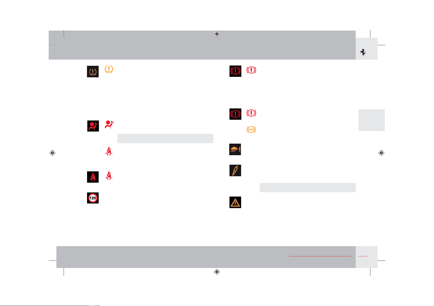
List of TFT display symbols and instrument panel warning
lights
TFT Warning
light
orange
orange
orange
orange
orange
red
Alarm system failure
Indicates a fault in the alarm system
(priority level 1).
The system is not programmed (priority level 2).
Failure and system not programmed
(priority level 1).
Alarm system failure (priority level 2).
Break-in attempted (priority level 2).
Contact the Ferrari Service Network.
Fuel level low
Indicates that the fuel level is too low
(priority level 2).
Battery conditioner connected
When the instrument panel is on, it indicates
that the battery conditioner is connected
(priority level 0).
Inertia switch
Indicates activation of the inertia switch following
an accident and the resulting cut-out of the fuel
supply (priority level 0).
Description and warnings
red
orange
orange
red
red
Alternator failure
If the recharging system is faulty.
red
When the battery is insufficiently charged or
overcharged (flashing).
Oil temperature
Indicates that the oil temperature is too high
orange
(priority level 0).
Adaptive light system failure
Indicates an adaptive light system failure
orange
(priority level 2).
Engine coolant temperature
Indicates that the engine coolant temperature is
red
too high (priority level 0).
Turn off the engine and contact the Ferrari
Service Network.
Oil pressure
red
Indicates that the oil pressure is too low
(priority level 0).
Turn off the engine and contact the Ferrari
Service Network.
Indicates a pressure sensor failure (flashing)
(priority level 2).
148
The hazard warning lights are also
automatically activated.
About your Vehicle
Page 8

orange
green
orange
orange
orange
Engine diagnostic system (EOBD) failure
While the engine is running, it indicates a fault in
orange
the emission control system and in the ignition/
injection system.
After turning the ignition key to position II, it
remains on for a self-check for a few seconds after
the engine has started.
Cruise Control
Indicates that the Cruise Control has been
activated/deactivated.
green
Running lights
Indicates that the running lights or low beam
green
lights are on.
Stop lights failure
Indicates a system failure or blowing of the STOP
light bulb (priority level 2).
External lights failure
Indicates a system fault or blowing of a bulb
in the running, turn indicator or rear fog lights
(priority level 2).
Number plate lights failure
Indicates a system failure or blowing of the
number plate light bulb (priority level 2).
Rear fog lights
Indicates a rear fog light failure.
orange
orange
red
red
Twilight sensor failure
Indicates a twilight sensor failure (priority level 2).
Hard top failure
Indicates a failure in the retractable hard top
(priority level 0).
The type of failure is specified by a special
message on the display.
High beams
Indicates that the high beam lights are on.
blue
The light also comes on when flashing.
Right turn indicators
Indicates that the right turn indicator is on.
green
Left turn indicators
Indicates that the left turn indicator is on.
green
Hazard warning lights
Simultaneous switching on of the right and left
green
turn indicator warning lights indicates that the
hazard warning lights are on.
Catalytic converter temperature
Indicates that the catalytic converter temperature
is too high: stop the vehicle (priority level 0).
Contact the Ferrari Service Network.
3
About your Vehicle
149
Page 9
orange
orange
orange
orange
orange
orange
Indicates that the catalytic converter temperature
is very high: reduce speed until the symbol goes
out (priority level 1).
Indicates a failure in the catalytic converter
temperature sensor (priority level 0).
Checking the engine oil level
Indicates a low engine oil level.
Seat heating
Indicates that the seat heating function is activated
(front RH/LH) (remains displayed for 5 seconds).
Power steering failure
Indicates that the power steering system is
inefficient (priority level 2).
Contact the Ferrari Service Network.
Low windscreen washer fluid level
Indicates a low level of washer fluid in the
windscreen washer tank (priority level 2).
ABS
Indicates an ABS system failure (priority level 1).
orange
The standard braking system is still
functioning.
Contact the Ferrari Service Network.
orange
orange
orange
ESC off
Symbol and warning light indicate that the ESC
orange
system has been deactivated (priority level 1).
The symbol is displayed for 5 seconds together
with the “ESC off ” message.
ESC system failure
Indicates a fault in the ESC system
orange
(priority level 1).
Warning
Stop the vehicle avoiding sharp braking. Stop
driving and contact the Ferrari Service
Network immediately.
Warning
The vehicle can still be driven at low speed
(max. 40 km/h) to clear the road.
ESC system activation (flashing warning light)
Indicates that the ESC system has been activated
orange
(priority level 1).
CCM brake discs worn
Indicates that the carbon ceramic discs are worn
(priority level 2).
Contact the Ferrari Service Network.
150
About your Vehicle
Page 10
orange
red
red
TPMS
Indicates a puncture in one or more standard
orange
tyres (priority level 0) or Run Flat tyres
(priority level 2).
With the warning light in flashing mode for a
maximum of 90 seconds after which it remains on
in fixed mode, it indicates:
A failure in the TPMS (priority level 2).
TPMS temporarily inactive (priority level 2).
Airbag system failure (flashing warning light)
Indicates a system failure (priority level 0).
red
Contact the Ferrari Service Network.
Driver-side seat belt not fastened
Indicates that the driver-side seat belt has not
red
been fastened (priority level 0) together with an
acoustic signal lasting 90 sec.
Passenger-side seat belt not fastened
Indicates that the passenger-side seat belt is not
red
fastened (priority level 0).
Speed limit exceeded
Indicates that the speed set by the driver has
been exceeded (priority level 2), the figure shown
indicates the set speed.
red
red
orange
orange
orange
Brake malfunction
Indicates that the brake fluid level is low
red
(priority level 0).
Indicates an EPB (electric parking brake) failure
(priority level 0).
Indicates an overhaul of the Parking Brake system
(priority level 0).
Indicates an EBD system failure (priority level 0).
red
orange
Rain sensor failure
Indicates a rain sensor failure (priority level 2).
Suspension control system failure
Indicates a malfunction in the suspension control
system (priority level 2).
Contact the Ferrari Service Network.
Generic failure
Indicates an airbag warning light failure
(priority level 2).
Indicates a Manettino failure (priority level 1).
Indicates that the electrical system is faulty
(priority level 2).
3
About your Vehicle
151
Page 11
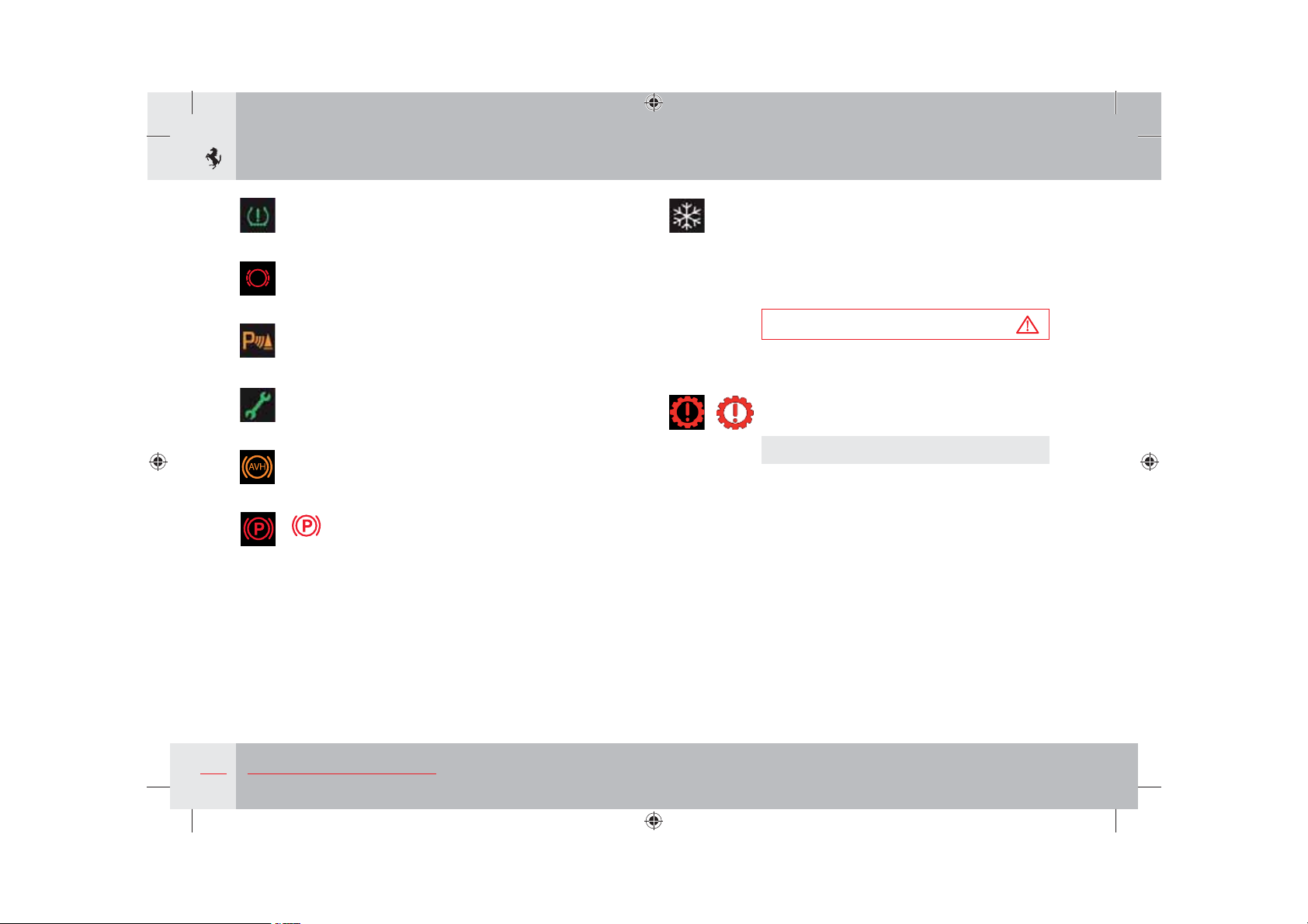
green
red
orange
green
orange
red
TPMS
Indicates that calibration of the TPMS has been
activated.
Brake pad wear
Indicates excessive wear of the brake pads
(priority level 2).
Parking sensor failure
Indicates that the parking sensor system is faulty
(priority level 2).
Scheduled Maintenance (Service)
Indicates the Scheduled Maintenance deadline.
AVH system
Indicates an AVH system failure (priority level 0).
Parking brake
Indicates that the parking brake is applied.
red
red
Ice hazard
Indicates that the outside temperature is 3 °C
(38 °F) or lower, highlighting the risk of icy road
surfaces.
Drive carefully in these conditions and slow down
since tyre grip is significantly reduced.
Warning
In this condition, do not activate the “SPORT”
mode.
Gearbox failure
Indicates a system failure (priority level 1).
red
Contact the Ferrari Service Network.
152
About your Vehicle
Page 12
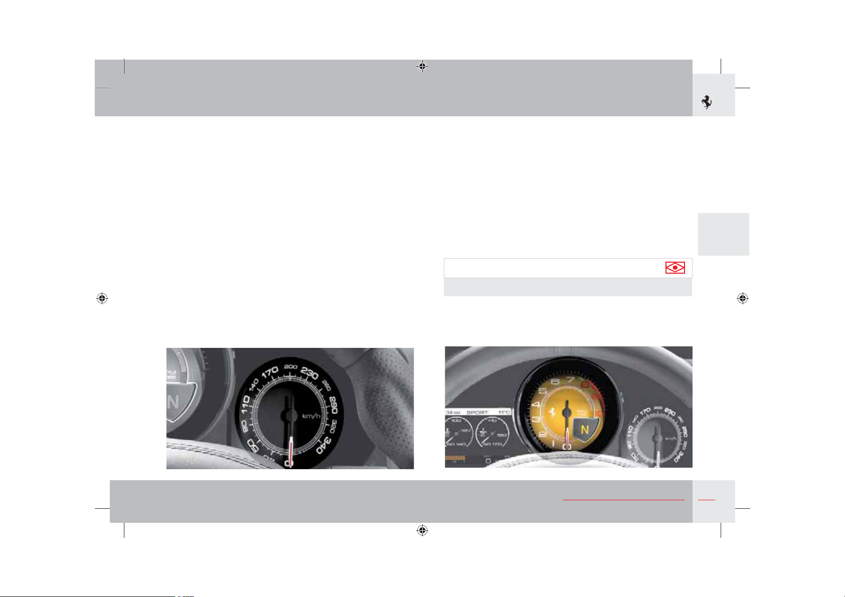
Electronic speedometer
It indicates the vehicle speed.
At a speed between 0 and 5 km/h, the indicator may remain idle.
With higher speeds, it indicates the speed measured.
Rev Counter
The electronic rev counter indicates the engine RPM. Avoid engine
speeds in the red sector.
Gearbox display
The display which gives information on dual clutch transmission
(DCT) is found to the bottom right of the rev counter; with the
ignition key in position II, it displays the following information:
- Gear engaged.
- Indication of “Automatic gearbox” mode.
- Indication of “Auto easy exit gearbox” mode.
- Indication of gearbox in “Parking” mode.
- Indication of Launch Control activated.
- Indication of AVH system activated.
Important note
Information on the gearbox is useful in all operating conditions.
3
About your Vehicle
153
Page 13
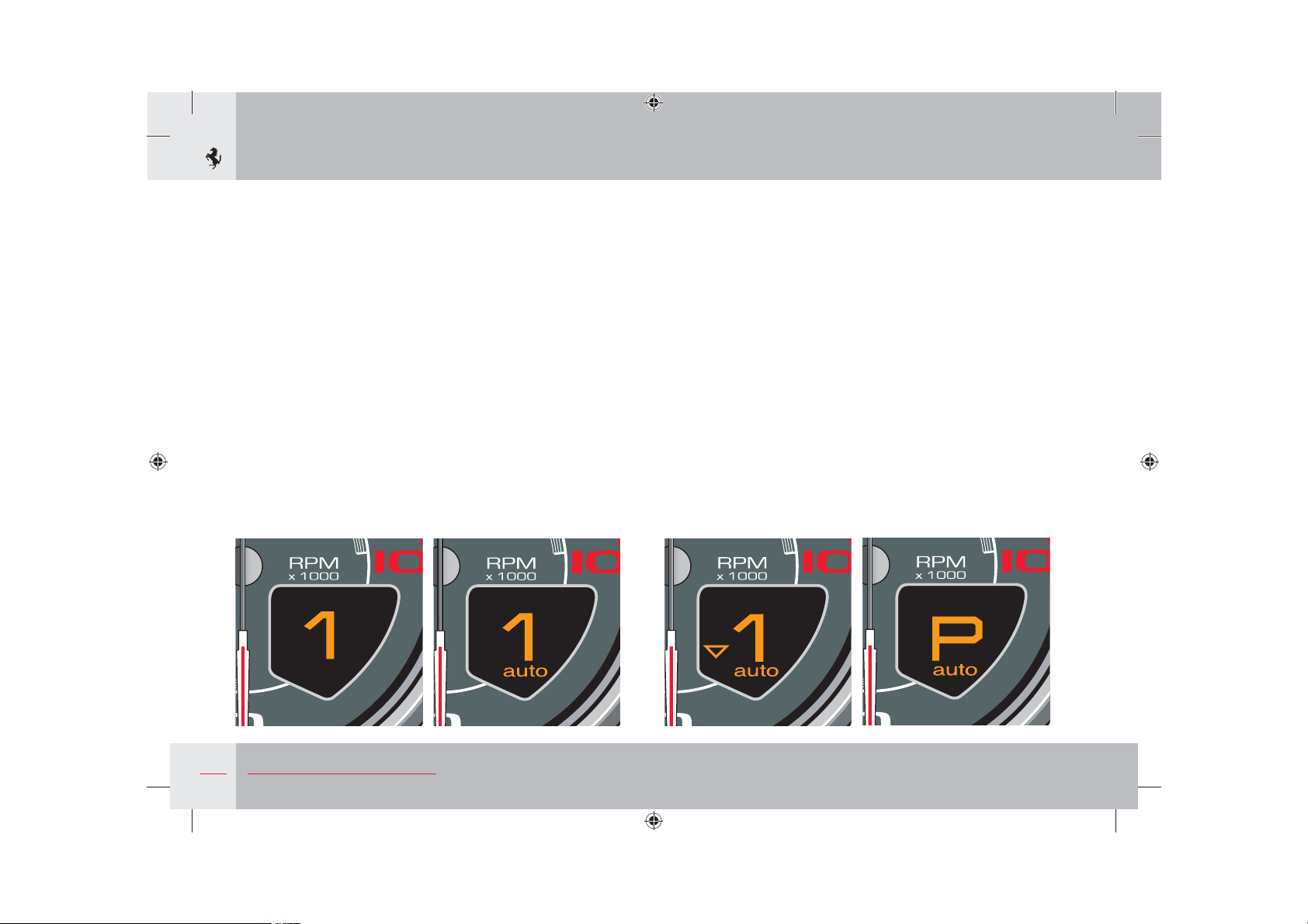
Gear engaged
The gearbox display shows the number or letter indicating the
engaged gear in the centre.
N Neutral
R Reverse
1 1
2 2
3 3
st
gear
nd
gear
rd
gear
4 etc.
When the key is turned to off, the display remains on for at least
3 seconds and displays the engaged gear. If the control panel reads
N (Neutral), the letter N is displayed and a buzzer will sound.
Indication of “Automatic gearbox” mode
When the gearbox is used in “automatic” mode (see page 172), the
word “auto” appears in the bottom of the gearbox display together
with the number or letter indicating the engaged gear.
Indication of “Auto easy exit” mode
When the gearbox is used in “Auto easy exit” mode (see page 172),
the word “auto” appears in the bottom of the display together with
a small “arrow” pointing downwards on the left.
Indication of gearbox in “Parking” mode
When the gearbox is in “Parking” mode, i.e. the Park Lock gearbox
locking device is activated (see page 179), the letter “P” appears in
the centre of the gearbox display.
154
About your Vehicle
Page 14
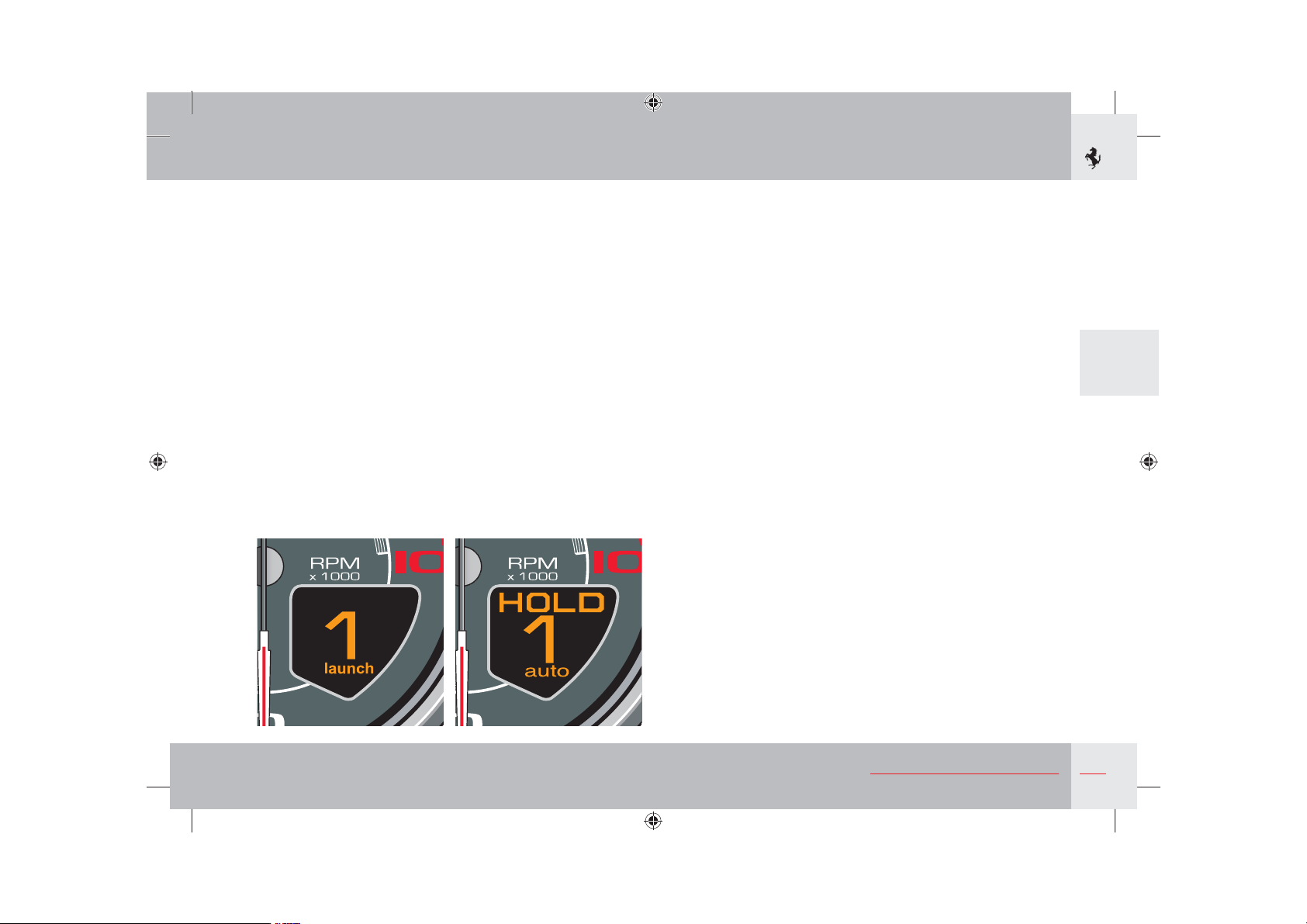
Indication of Launch Control activated
When the gearbox is used in “manual” mode and the Launch
Control function is requested by pressing the special button on
the centre console (see page 180), the word “launch” appears in
the bottom of the gearbox display. The word remains while the
function is activated.
Indication of AVH system activated
In certain circumstances, when the AVH system is activated (see
page 184), the word “HOLD” appears in the top of the gearbox
display.
3
About your Vehicle
155
Page 15
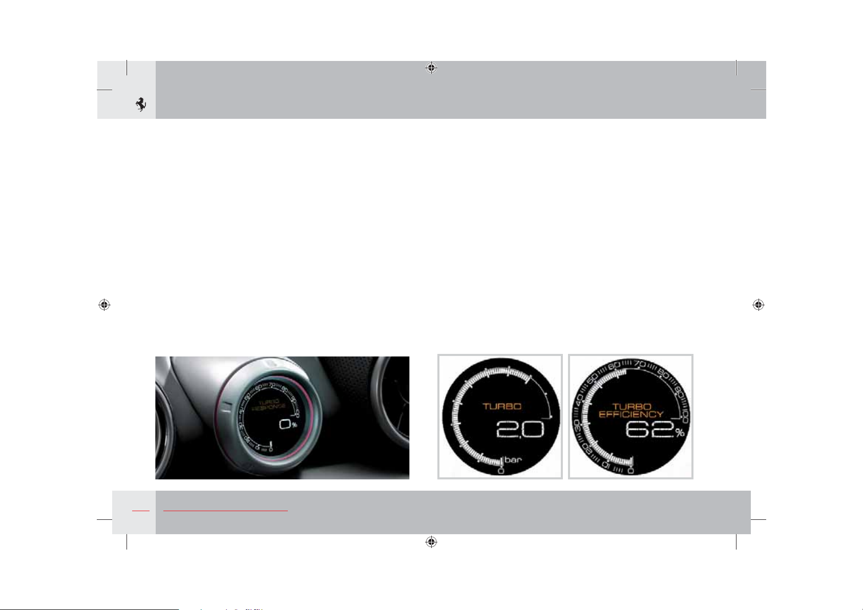
Turbo Performance Engineer (TPE) display
The TPE display can be activated by pressing the touch-sensitive
ring for 3 seconds. Each time it is pressed, it cyclically passes
through its 5 functions: time displayed in 12-hour format, external
temperature displayed in degrees Celsius or Fahrenheit, pressure
reading of turbo in bar or psi, and two screens that display the
main characteristics of the turbo engine.
- Turbo: indicates the working pressure of the turbocharger in bar
or psi.
- Turbo Efficiency (TE): indicates the percentage of maximum
turbo efficiency (seen as the maximum torque obtainable by the
car for a given fuel consumption level or specific amount of fuel
used) available to the driver depending on the number of revs.
156
About your Vehicle
Page 16
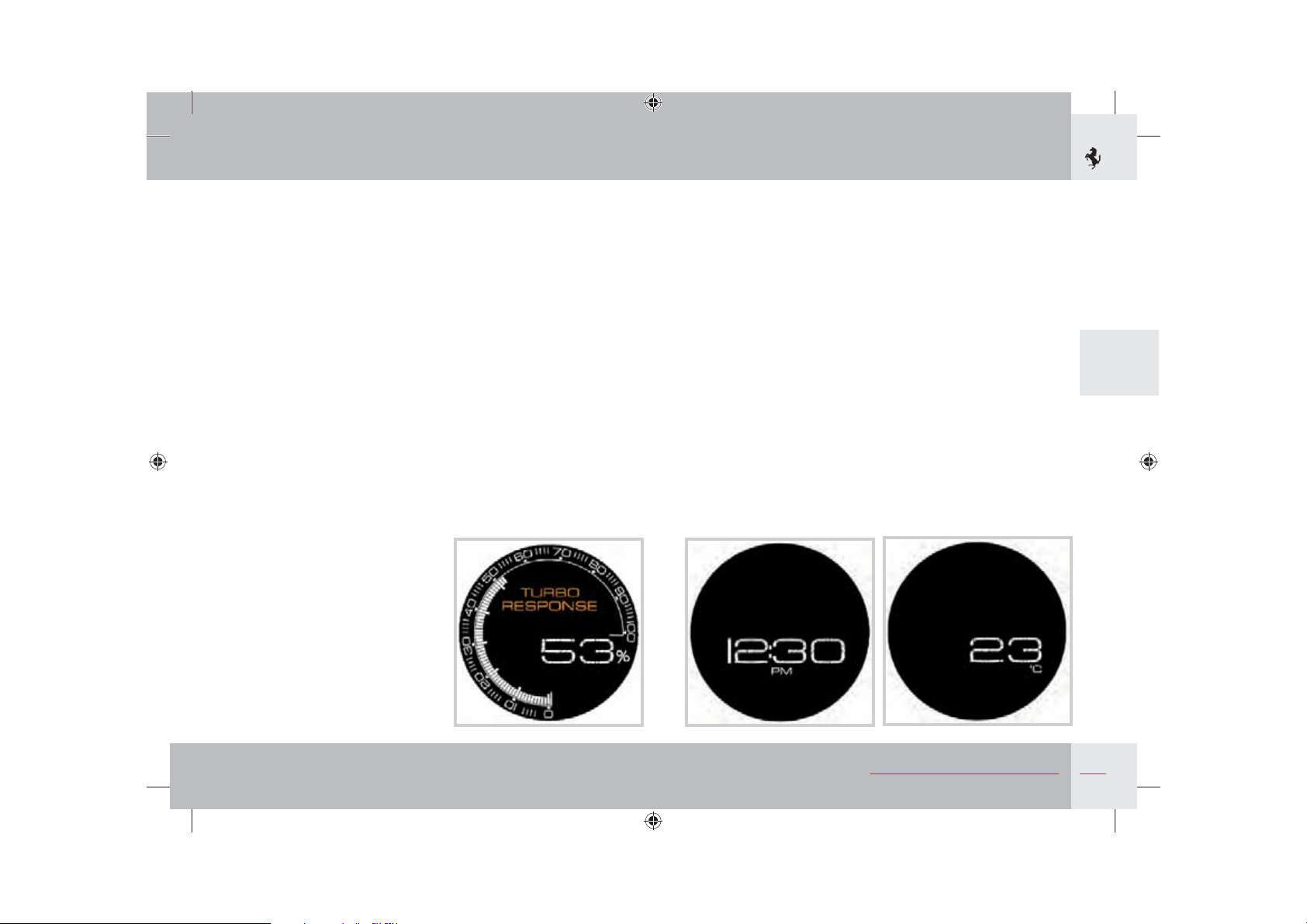
- Turbo Response (TR): indicates the percentage of maximum
engine response available to the driver depending on the number
of revs. For instance, using the gearbox and accelerator pedal to
push the engine to over 4000 RPM gives a very high % of TR
(80-90%): pressing the accelerator pedal hard down will give
instant engine response and acceleration.
- Time: displays a 12-hour format digital clock.
- External temperature: displays a digital thermometer, the
temperature can be displayed in degrees Celsius or Fahrenheit.
3
About your Vehicle
157
Page 17
Roof panel controls
Horn control
Door lock/unlock
Both doors can be locked by activating/deactivating the “LOCK/
UNLOCK”
Deactivating the anti-lift alarm
Press button
information, see page 18.
Front parking sensors (optional)
On vehicles fitted with front and rear parking sensors, the front
parking sensors are activated/deactivated by pressing button
When the front parking sensors are activated, the light on the
button comes on.
H button. For further information, see page 86.
L to deactivate the anti-lift alarm system. For further
M.
M
H
The horn can be used by pressing the horn symbol, on either side
of the steering wheel upper spokes.
L
158
About your Vehicle
Page 18
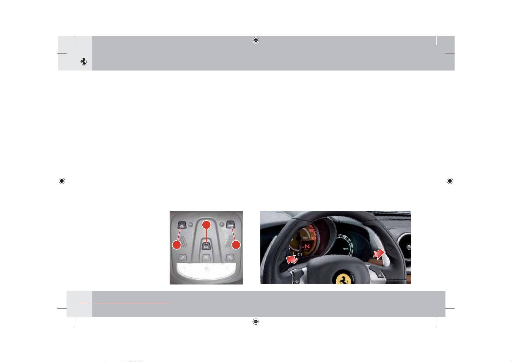
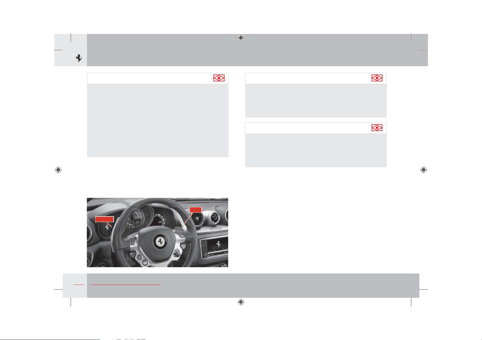
Controls on the steering wheel
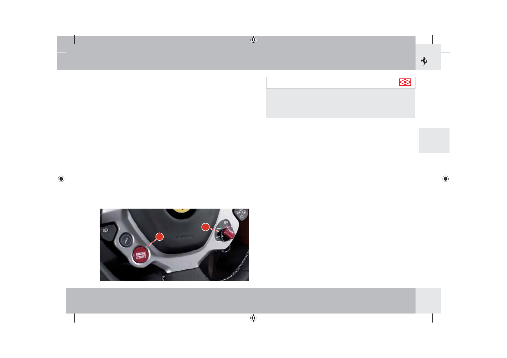
Start button
Press the ENGINE START button
engine has started, release the ENGINE START button.
Do not hold the ENGINE START button down for a long time.
Driving mode control switch “Manettino”
The driving mode selected does not exempt the driver from
complying with the rules of safe driving.
The driver can select the driving mode using the “Manettino”
according to the desired driving style.
A to start the engine. When the
B
A
Important note
In the event of a failure of one of the onboard systems, signalled
by the relative warning light on the TFT display, the switch
moves to a “recovery” position, but still allows the vehicle to be
driven. In these cases, contact the Ferrari Service Network.
3
B,
About your Vehicle
159
Page 19
Driving modes that can be selected with “Manettino”
COMFORT mode
This is recommended for everyday driving.
SPORT mode
This is the ideal setting for vehicle performance.
Select SPORT mode for sports-style driving, under high-grip
conditions.
Activation will be signalled by the SPORT icon in the dedicated
area on the TFT display.
ESC OFF mode
Select this mode to deactivate the ESC system (always active when
the engine is started).
When the system has been deactivated, a warning light comes on
on the instrument panel (see page 150); the symbol appears on the
TFT display for 5 seconds together with the “ESC off” message.
When the ESC system has been activated, a warning light flashes on
the instrument panel (see page 150).
Warning
In low- to medium-grip conditions (e.g. wet, icy, sandy roads),
do not deactivate the ESC system and do not select SPORT
mode.
Important note
When “ESC OFF” mode is selected, the Manettino lever
automatically goes back to “SPORT” mode: this occurs because
each time the engine is started, the ESC system is reactivated.
Important note
When the brake pedal is pressed, traction control is activated
via the VDC system (vehicle dynamics control via the braking
system).
160
About your Vehicle
Page 20
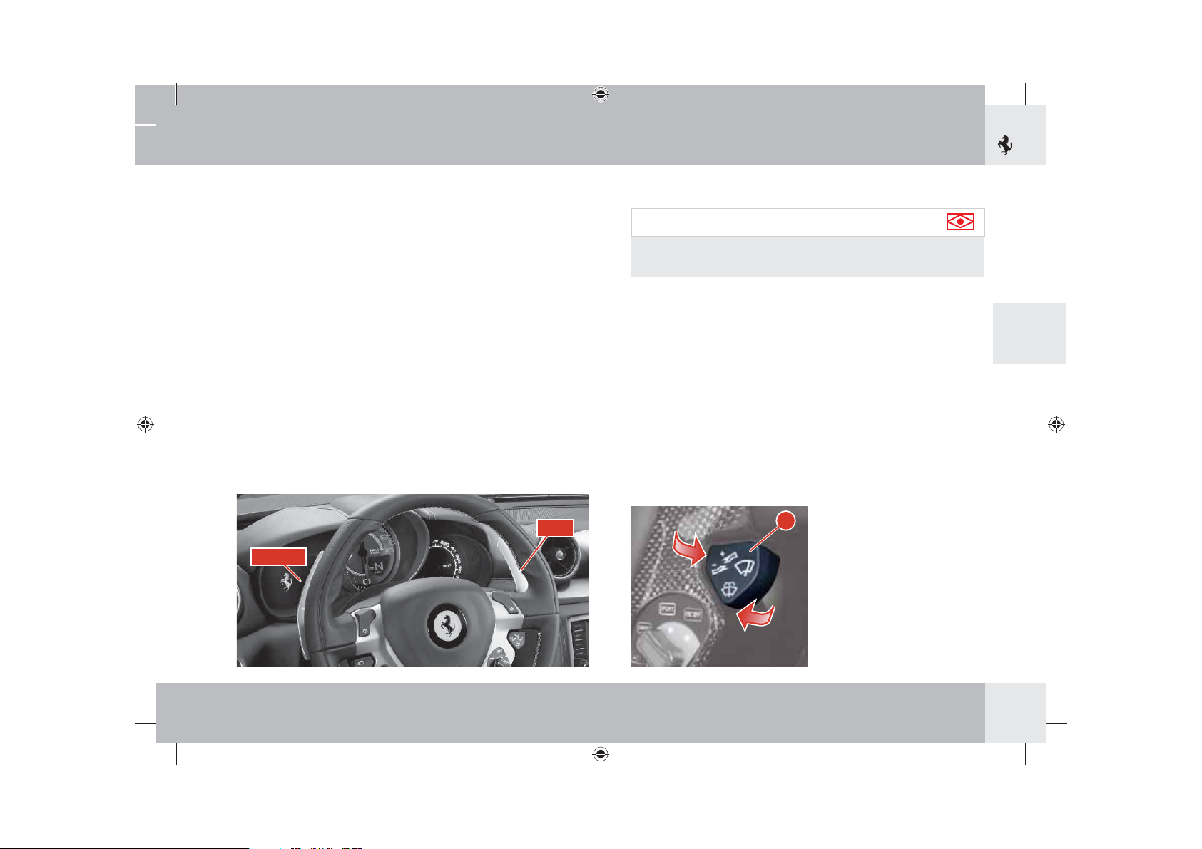
“UP” shift paddle
Pull the right-hand UP paddle towards the steering wheel to shift
gears up.
“DOWN” shift paddle
Pull the left-hand DOWN paddle towards the steering wheel to
shift gears down.
Windscreen and headlight washer/wipers
Important note
The windscreen wipers and washer work only with the ignition
key in position II.
The windscreen wipers have 4 different speeds:
OFF Windscreen wipers stationary.
AUTO The rain sensor adjusts the windscreen wiper timing to the
intensity of the rain.
1 Slow continuous operation.
2 Fast continuous operation.
With the wipers stationary (OFF), quickly pressing lever
the dashboard activates the windscreen wipers in AUTO speed.
With the wipers on, quickly pressing the lever towards the
dashboard increases windscreen wiper speed (from AUTO to 1,
from 1 to 2).
A towards
3
DOWN
UP
A
About your Vehicle
161
Page 21
Windscreen washer
To activate the windscreen washer, keep lever A pulled.
When the lever is released, the windscreen wiper returns to the
preset speed.
Warning
Do not start the windscreen washer during the cold months
until the windscreen has warmed up. If it has not warmed up,
the fluid could freeze on the glass and block the view.
Headlight washer
The headlight washer is activated automatically when the
windscreen washer is operated and the low beams are on. The
headlight washer and windscreen washer share the same fluid tank
and a low fluid level is indicated by the relative symbol on the left
TFT display.
Important note
The rain sensor function is deactivated by turning the ignition
key to position 0 and leaving the windscreen wiper in position
AUTO. To reactivate the system at the next key-on, set the
wipers to AUTO by quickly pressing the lever A towards the
dashboard.
Warning
Before cleaning the front windscreen (for example in service
stations) make sure the rain sensor is deactivated or that the key
is in position 0. The rain sensor must be deactivated also when
washing the vehicle by hand or in automatic car washes.
In case of ice or snow on the front windscreen, do not activate
the rain sensor to avoid damaging the wiper motor and/or
blades.
Rain sensor
The rain sensor automatically adjusts the windscreen wiper timing
to the intensity of the rain. The system is activated by moving the
windscreen wiper to AUTO.
When operating automatically, the wiper speed ranges from a
minimum intermittent setting (one wipe every 5 seconds approx.)
when the windscreen is damp to fast continuous operation in heavy
rain.
162
About your Vehicle
Rain sensor failure
If there is a rain sensor failure, indicated by a special symbol on
the left TFT display (see page 151) while the windscreen wiper
is set to AUTO, the wipers will be set to intermittent operation
with one wipe every 1 second approximately. If this is the case, we
recommend that you deactivate the rain sensor and turn on the
wipers, if necessary, in continuous mode.
Important note
If this occurs, contact the Ferrari Service Network as soon as
possible.
Page 22
Cruise control
The Cruise Control is an electronic device designed to help the
driver drive at a constant speed of over 50 km/h without having to
keep the accelerator pedal pressed.
Important note
We recommend only using the device on long, dry stretches of
road requiring few gear changes (e.g. motorways).
Do not use the device for city driving.
Important note
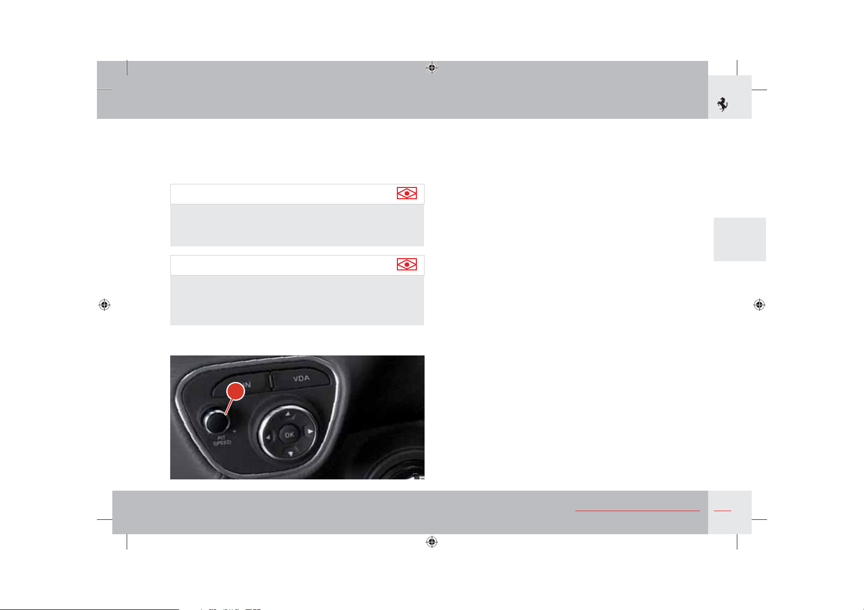
PIT SPEED is a term taken from the motor sports world used by
Ferrari to indicate the speed memorised using the device and
does not endorse inappropriate behaviour on the road which
does not comply with Traffic Regulations.
A
Activating the device
To activate the device, hold down control A for at least 2 seconds.
When the system is activated, a warning lamp lights on the
instrument panel (see page 149), and the message “Cruise Control
ON”, together with the specific symbol, are shown for 5 seconds on
the left hand TFT display.
The device cannot be activated when reverse or 1
engaged.
When going down slopes with the device on, the vehicle speed may
be slightly higher than the memorised speed.
Memorising the speed
Proceed as follows:
with the device activated, bring the vehicle to the desired speed
by pressing the accelerator pedal;
- turn control
release it: the speed of the vehicle is memorised and you can
release the accelerator pedal.
If necessary, you can accelerate by pressing the accelerator pedal:
when the pedal is released, the vehicle will return to the previously
memorised speed.
A clockwise (+) for at least 3 seconds and then
st
gear are
3
About your Vehicle
163
Page 23
Resetting the memorised speed
If the device has been turned off by pressing the brake pedal, the
memorised speed can be reset as follows:
- gradually accelerate until the vehicle reaches a speed which is
close to the memorised speed;
- quickly press control
Increasing the memorised speed
This can be done in two ways: by pressing the accelerator and
memorising the new speed reached or by turning control
clockwise (+).
One turn of the control corresponds to an increase in speed of
about 2 km/h; if the control is kept turned on the other hand, the
speed continually increases.
Reducing the memorised speed
This can be done in two ways: by deactivating the device
and then memorising the new speed or by turning control
counterclockwise (-).
One turn of the control corresponds to a decrease in speed of
about 2 km/h; if the control is kept turned on the other hand, the
speed continually decreases.
A.
A
A
Deactivating the device
Hold down control
key to position 0. The device is also automatically deactivated by
pressing the brake pedal.
When it is deactivated, the warning light on the instrument panel
goes out and a “Cruise Control OFF” message accompanied by a
special symbol appears on the left TFT display for 5 seconds.
A for at least 2 seconds or turn the ignition
Warning
While driving with the device activated, do not put the vehicle
into “N” (neutral).
164
About your Vehicle
Page 24
Driving the vehicle
Running-in
The latest manufacturing techniques have allowed us to achieve
high precision and accuracy levels in the construction and assembly
of components. Nonetheless, the vehicle movable parts undergo a
settling process, basically during the first hours of operation.
Engine and transmission
Avoid exceeding 5,000 RPM for the first 1,000 km.
After starting, do not exceed 4,000 RPM until the engine has
warmed up (oil temperature: 65-70 °C / 149-158 °F).
Do not let the engine run at a constantly high speed for a
prolonged time.
Warning
BEFORE YOU DRIVE
Check that the seat belts are fastened.
Check that the doors are closed.
Check that the seat is properly adjusted.
Check the rear-view mirror adjustment
(central and sides).
3
About your Vehicle
165
Page 25
Before a trip
Preliminary checks
Check the following at regular intervals and always before long
trips:
- tyre pressure and condition;
- levels of fluids and lubricants;
- condition of the windscreen wiper blades;
- proper functioning of the warning lights and external lights.
Important note
In any case, it is advisable to perform these checks at least every
1000 km and always comply with the maintenance schedule.
It is also advisable to:
- clean the glass covers of the external lights and all the glass
surfaces;
- properly adjust the mirrors, steering wheel, seats and seat belts.
Refilling
Warning
Use unleaded fuel only!
Using leaded fuel would permanently damage the catalytic
converters.
For specifications and quantities of lubricants and fluids, refer to
the “Refilling” table on page 36.
166
About your Vehicle
Page 26
Starting and driving the vehicle
System start-up
After turning the ignition key to position II (key-on), the TFT
display is activated on the instrument panel and system diagnosis
is performed. During diagnosis, which lasts 5 seconds, a check is
performed on the warning lights on the panel and the presence of
any faults is checked.
If diagnosis detects any errors, they are only displayed once the
5 seconds required for the check have elapsed. The cases listed
below are an exception and errors are displayed as soon as the key
is turned to on, even during diagnosis:
- Low engine oil pressure (see page 148).
- Inertia switch triggered (see page 148).
- Semi-automatic gearbox safety warnings.
- Deactivation of EPB warning (see page 183).
If the next scheduled maintenance deadline is approaching, each
time the key is turned to on, information on scheduled maintenance
is automatically displayed after diagnosis. For further information,
refer to the “Maintenance Schedule” paragraph on page 252.
Finally, each time the key is turned to on, the message for activation
of the alarm when an intrusion has been attempted (see page 19) is
also displayed (after diagnosis).
Once the system check has been completed, the gearbox display
is activated and the letter “P” (Parking) or “N” (Neutral) will be
displayed.
Important note
BEFORE YOU DRIVE
If the warning light A does not turn off after diagnosis,
indicating a fault in the gearbox (which is also indicated by
the symbol and specific message on the TFT display - see
page 152), contact the Ferrari Service Network.
3
A
About your Vehicle
167
Page 27
Important note
The vehicle is equipped with an electro-hydraulically controlled
gearbox system operated by means of paddles on the steering
wheel.
The default setting for the DCT gearbox is always “Automatic”
mode (see page 172).
Every time the vehicle is started, the DCT gearbox is in “Auto
easy exit” mode (see page 172) unless the vehicle was in
“Automatic” mode when the engine was turned off.
To exit the “Auto easy exit” mode operate the UP and DOWN
paddles (while the vehicle is moving) or
on the centre console.
DOWN
press the
AUTO
UP
button
Important note
Immediately release the UP and DOWN paddles or button R
after the gearbox display shows that the gear has been engaged;
a prolonged manoeuvre would cause the gearbox failure
warning light to turn on (see page 152) and triggering of the
buzzer.
Important note
If the engine compartment lid is open or not properly closed,
none of the gears can be engaged. When the vehicle is
stationary, with the driver-side door open or not properly closed
and the brake pedal released, the system disengages the gear
engaged after approximately two seconds.
168
About your Vehicle
Page 28
Starting the engine
Before starting the engine, make sure that the alarm system and all
electrical devices with high power absorption are turned off.
s-AKESURETHATTHEELECTRICPARKINGBRAKEISAPPLIEDANDTHATTHE
doors are closed.
s(OLDTHEBRAKEPEDALDOWNWHENSTARTINGTHEENGINE
If the engine fails to start after several attempts, check for one of
the following causes:
sINSUFlCIENTSPEEDOFTHESTARTERMOTORmATBATTERY
sIGNITIONDEVICEFAULTY
sELECTRICALCONTACTSFAULTY
sFUELPUMPFUSESBLOWN
Warning
Do not press the accelerator pedal.
s4URNTHEIGNITIONKEYTOPOSITIONII and wait for the gearbox
display to come on.
s0RESSTHE
soon as the engine starts.
Do not hold the
time.
If the engine does not start, turn the key back to position 0 and
wait for the gear display to go off before retrying.
ENGINE START button (see page 159) and release it as
ENGINE START button pressed down for a long
Warning
Hold the brake pedal down while starting the engine.
Warming up the engine
Do not run the engine at high speed until the engine oil temperature
has reached at least 65-70 °C (149-158 °F), approximately.
Starting the vehicle
With the engine started, the vehicle stationary and the brake pedal
pressed, pull the right-hand UP paddle towards the steering wheel
to engage 1
Release the brake pedal and press the accelerator to start off.
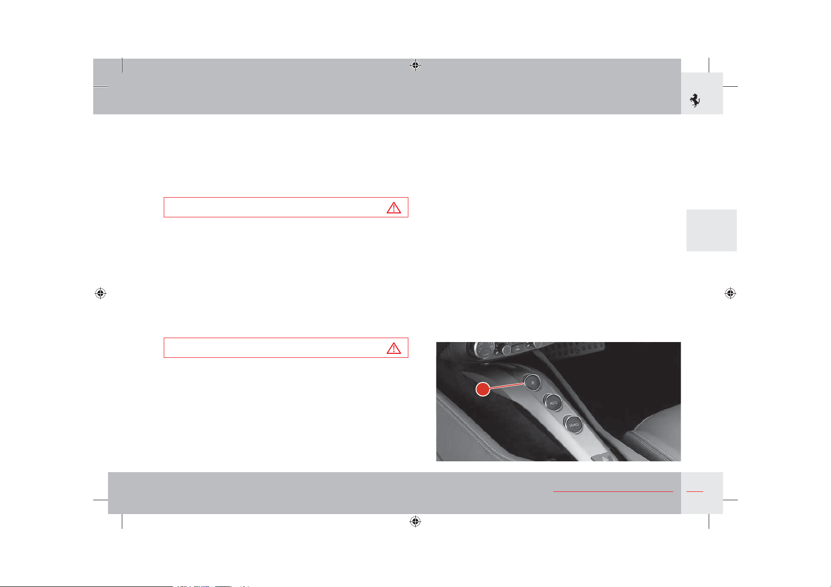
With the engine running and the vehicle stationary, you can change
directly from 1
centre console and from reverse to 1
st
gear.
st
or 2nd gear to “R” (reverse) by pressing R on the
R
st
by moving the UP paddle.
About your Vehicle
3
169
Page 29
Warning
If the UP and DOWN paddles are not working, the message
“Depress brake pedal and press LAUNCH to engage gear” will
appear on the TFT display; you can therefore engage the gear
by pressing the LAUNCH button on the centre console (see
page 180) and the brake pedal.
In these cases, the “Launch Control” function is not available.
If the engaged gear was R, the LAUNCH button must be pressed
twice to engage 1
st
gear.
Important note
When reverse is selected, an acoustic safety signal beeps
intermittently as long as “R” is engaged.
If the system automatically selects 2
shift from R to 1st gear, this indicates that 1st gear has jammed.
Therefore, this is not a malfunction, as it falls within the system
operating logic. For the same reason, when shifting from 1
to “R”, the system will automatically engage “N” if the gear has
jammed.
During prolonged stops with the engine running, it is advisable to
keep the gearshift in “N”.
nd
gear when attempting to
st
gear
Important note
If you allow the vehicle to move forward in N, when UP or
DOWN is requested, a gear will be engaged that corresponds to
the speed of the vehicle.
UP-shifting
Operate the right-hand UP paddle without releasing the accelerator
pedal.
An UP-shift request is not accepted when engagement of the
requested gear forces the engine to underrev or if an UP-shift is
already in progress because of engine overrevving.
Gearshifting will be much quicker if the request is made with
the accelerator pedal pushed right down and the engine at over
5,500 rpm.
In any event, it is advisable to:
sShift gears without releasing the accelerator pedal if pressed.
sWait until gearshifting has been completed before requesting the
next shift, avoiding a rapid sequence of multiple requests.
UP-shifting due to overrevving
The system “automatically” engages a higher gear if the accelerator
pedal is pressed and the engine approaches the “runaway speed rate”
(overrevving).
Important note
This will not occur when the system is in “SPORT” and “ESC
OFF” driving mode.
170
About your Vehicle
Page 30
DOWN-shifting
Use the left-hand DOWN paddle without releasing the accelerator
pedal.
A DOWN-shift request is not accepted if engagement of the
requested gear forces the engine beyond a certain RPM, depending
on the gear requested, or if a DOWN-shift is already in progress
because of engine underrevving.
In any event, it is advisable to:
s Shift gears without releasing the accelerator pedal if pressed.
s If DOWN-shifting is requested to start overtaking which requires
quick acceleration, press the accelerator pedal just before using
the paddle.
sWait until gearshifting has been completed before requesting the
next shift, avoiding a rapid sequence of multiple requests.
DOWN-shifting due to underrevving
sThe system shifts down “automatically” if the engine goes below a
minimum number of revs (1250 RPM).
sThe DOWN-shift request from the paddle is ignored if
gearshifting is already in progress due to engine underrevving.
“N” (Neutral) request
With the engine running, pull both UP and DOWN paddles towards
the steering wheel at the same time without pressing the brake pedal
to request neutral “N”.
If necessary, “N” can be requested at any speed.
Subsequently, if an “UP” or “DOWN” shift is requested, the system
will engage the gear most suited to the speed of the vehicle.
Stopping the vehicle
When the vehicle stops, the system automatically engages 1
unless Neutral has already been requested.
When the vehicle is stationary and the engine is running, hold the
brake pedal down until ready to move off again.
Switching off the engine
The engine can be switched off with the gearbox either in “N” or
with a gear engaged.
After turning the ignition key from position II to position 0, the
gearbox display will remain on for a few more seconds to display
the engaged gear. If the gearbox is in “N” a buzzer will sound.
Before switching off, the letter “P” is displayed on the gearbox
display to inform the driver that the Park Lock has been activated.
st
gear
Warning
Never leave the vehicle with the gearbox in “N”. Always make sure
that the letter “P” (Parking) appears on the gearbox display.
Warning
Never leave the vehicle with the engine running.
Important note
If the vehicle is not in Parking mode (the letter “P” must be
displayed on the gearbox display), the key cannot be removed.
3
For information on the Park Lock, see page 179.
About your Vehicle
171
Page 31

“Automatic gearbox” mode
The “Automatic gearbox” mode is enabled/disabled by pressing the
AUTO button on the centre console. When the “Automatic” mode
is enabled, the word “auto” appears on the gearbox display. To exit
the “Automatic” mode, you must press the AUTO button until the
word “auto” on the gearbox display disappears.
When the “Automatic Gearbox” mode is enabled, the system will
automatically UP-shift and DOWN-shift according to vehicle speed,
engine revs and the torque/power request of the driver.
When you are in “Automatic” mode, you can however manually
shift gears using the UP and DOWN paddles. The system remains
in “Automatic” mode: this is indicated by the word “auto” that
remains on the gearbox display in flashing mode when the paddles
are used.
When the vehicle is stationary, a “N”, 1
result in a change from “Automatic” to “Manual”.
st
gear or “R”request will not
“Auto easy exit” mode
Every time the vehicle is started, the gearbox starts in “Auto easy
exit” mode unless it was in “Automatic” mode when the engine was
turned off. In this case, it remains in “Automatic” mode the next
time the engine is started.
Activation is signalled by the word “auto” and an arrow
gearbox display.
In this mode, the system will automatically UP-shift and DOWNshift according to vehicle speed, engine revs and the torque/power
request of the driver.
To exit the “Auto easy exit” mode and go to “Manual” mode,
operate the UP or DOWN paddle (while the vehicle is moving) or
press the AUTO button on the centre console.
If the “Automatic” gearbox mode is then requested by pressing the
AUTO button, the system will apply all the characteristics of the
“Automatic” gearbox mode.
Push start
in the
Warning
Push starting is not allowed.
172
About your Vehicle
Page 32

Safe driving
For safe driving, it is essential that the driver be aware of the best
driving techniques suited to various circumstances. Always try to
prevent dangerous situations by driving with caution.
Before you drive
- Adjust the position of the seat, steering wheel and rear-view
mirrors, in order to obtain the best driving position.
- Adjust the backrest so that your chest is upright and your head is
as close to the headrest as possible.
- Carefully adjust the headrest so that your head, and not the neck,
is resting against it. Ensure that nothing (e.g. mat covers, etc.) is
blocking the pedals.
- Check that the lights and headlights are working properly.
- Ensure that any child restraint systems (e.g. child seats, cradles
etc.) are properly fixed on the passenger seat.
- Your reflexes are quicker if you eat lightly before driving: avoid
heavy meals before a trip.
- Do not drink alcoholic drinks before and during the journey.
At regular intervals, check the following:
- Tyre pressure and condition
- Engine oil level
- Engine coolant level and system condition
- Brake fluid level
- Steering fluid level
- Windscreen washer fluid level.
While travelling
- Caution is the number one rule for safe driving, which also means
you should take other people’s behaviour into consideration.
- Follow the Road Regulations in force in the country you are
driving in and always respect the speed limit.
- Always make sure that the driver and passengers have their seat
belts fastened and that all children are travelling in suitable child
seats.
- Good personal physical conditions ensure you can drive long
distances safely.
3
About your Vehicle
173
Page 33

Warning
Driving under the influence of drugs or certain medications is
dangerous to yourself and others as well as contravening road
regulations and legal norms.
Travelling without your seat belt fastened increases the risk
of serious injury and death in the event of a collision. Always
fasten the seat belt and the child seat, if any.
Deactivate the passenger’s airbag (where possible) if a child seat
is fitted on the front seat.
Do not travel with objects lying around on the floor, especially
in front of the driver’s seat: in the event of braking, these
could slide under the pedals, making it impossible to brake or
accelerate.
Additionally, ensure that any loose floor mats sit correctly.
Water, ice and salt spread on icy roads may deposit on the brake
discs and reduce the efficiency of the initial braking.
- Make regular stops to loosen up your limbs and refresh yourself
and avoid driving for hours on end.
- Keep a constant air circulation in the passenger compartment.
- Never coast downhill with the engine off: in these conditions
the engine brake, servo brake and power steering are inefficient,
braking requires greater pressure on the pedal and steering will
be harder.
Driving at night
When you are travelling at night, follow these fundamental rules:
- Reduce speed, particularly on dark roads.
- Drive with due caution in consideration of the reduced visibility.
- If you start feeling tired or sleepy, stop immediately: to continue
driving would be a risk for yourself and for others. Continue only
after you have had a rest.
At night, it is difficult to judge the speed of vehicles in front of
you as you can only see their taillights: keep at a greater safety
distance than you would during the day.
- Use the high beams only outside of urban areas and when you are
sure that they will not disturb other drivers.
- Turn off the high beams when you see oncoming vehicles and use
the low beams.
- Keep the lights and headlights clean.
- Watch out for animals crossing the road when travelling outside
urban areas.
Driving in the rain
Rain and wet roads can cause hazardous situations.
All manoeuvres are more difficult on a wet road, as the tyres have
significantly less grip on the road. This means that the braking
distances increase considerably and road-holding decreases.
Here is some advice for driving in the rain:
- Keep a greater safety distance between yourself and the other
vehicles and reduce your speed.
- When it is raining very hard, visibility is also reduced. In these
cases, to make yourself more visible to others, turn on the low
beams even during the day.
174
About your Vehicle
Page 34

- Do not drive through puddles at high speeds since you do not
know how deep they may be; Travelling through a puddle at high
speed can result in losing control of the vehicle (“aquaplaning”):
if this occurs, grip the steering wheel firmly.
Warning
If the road is wet, reduce your speed to avoid “aquaplaning”
(during which the tyre no longer touches the road surface. This
is due to the fact that, when the road is very wet and vehicle
speed is high, because of their particular shape or insufficient
depth, the side channels of the tyre tread are not capable of
removing all of the water channelled so that a layer of water is
placed between the road surface and the tyre. The fluid pressure
generated is so high that it supports the vehicle's weight making
it virtually impossible for the driver to control the vehicle).
- Use the ventilation system to demist the windscreen (see
page 199) and avoid visibility problems.
- Periodically check the condition of the windscreen wiper blades.
Driving in fog
Whenever possible, avoid travelling if there is thick fog. If you have
to drive in misty conditions, or if there is thick fog or fog banks,
follow these rules:
- Keep a moderate speed.
- Turn on the low beams, also during the day, and use the rear fog
light. Avoid using the high beams.
Warning
On stretches where visibility is good, turn off the rear fog light,
it may be annoying for the occupants of the vehicles behind
you.
- Remember that fog makes the road damp and therefore all
manoeuvres are more difficult and braking distances are longer.
- Keep a safe distance from the vehicle in front of you.
- As far as possible, avoid suddenly changing speed and direction.
- As far as possible, avoid overtaking.
- In the event of an emergency stop, (e.g. failures, inability to
proceed due to poor visibility conditions, etc.) try to free the
main driving lane. Then turn on the hazard warning lights and, if
possible, the low beams. On approaching another vehicle, sound
the horn rhythmically.
Driving on mountain roads
Below is some advice for driving on steep mountain roads:
- To prevent the brakes from overheating when driving downhill,
use the engine to brake by engaging a lower gear.
- Never coast downhill or drive downhill with the engine off or
in neutral, nor with the ignition key removed from the steering
column.
Drive at a moderate speeds and do not “cut” corners.
-
- Remember that overtaking uphill is slower and requires a longer
free stretch of road. If you are overtaken when driving uphill,
ensure that the other vehicle can pass easily.
3
About your Vehicle
175
Page 35

Driving on snowy or icy roads
Below is some advice for driving in these conditions:
- Keep a very moderate speed.
- Keep a safe distance from the vehicles in front of you.
- Fit snow tyres approved for the vehicle.
- Given the poor grip, use the engine brake as much as possible
and avoid sudden braking.
- Avoid sudden acceleration and sharp changes in direction.
- During the winter season, even apparently dry roads can have icy
sections.
Therefore, be careful when driving along stretches of road in the
shade as there may be icy patches.
Driving with the “ABS” braking system
The ABS system assists the driver as follows:
- It prevents the wheels from locking and skidding during
emergency braking, particularly in low-grip conditions.
- It allows braking and changing direction at the same time. This
feature is affected by the physical limits and lateral grip of the
tyres.
- When the ABS is activated, you will feel a slight pulsing of the
brake pedal during emergency braking or in low grip conditions.
Do not release the pedal but continue to push it to give continuity
to the braking action.
- The ABS prevents the wheels from locking, but it does not
increase the physical limits of grip between the tyres and the road:
keep a safe distance from the vehicles ahead and reduce speed
before curves.
Power steering system
The power steering system uses the power produced by the engine
to help the driver steer more precisely while exerting less force on
the steering wheel.
Important note
Remember that power steering does not work when the engine
is switched off and more force is therefore needed when
steering.
Warning
Do not keep the steering wheel fully turned (locked position) to
the right or the left for more than 15 seconds when the engine is
running. This may damage the power steering system.
Important note
If the power steering system is not working properly, as
indicated by a symbol which appears on the TFT display (see
page 150), contact the Ferrari Service Network.
176
About your Vehicle
Page 36

Driving using the driving mode control switch
(“Manettino”)
The driving mode control switch A on the steering wheel, allows
the driver to use the vehicle potential in a quick and easy way.
There are three modes available which can be selected according
to the grip level (from low to high) and consequently the level of
driving assistance required (from high to none).
- The COMFORT mode is recommended for everyday driving.
If COMFORT mode is selected, it is indicated on the TFT display
as shown below:
3
COMFORT
A
About your Vehicle
177
Page 37

- SPORT mode is the vehicle driving mode that provides the best
compromise between stability and performance. This setting
ensures stability in medium- to high-grip conditions only (for
low-grip road surfaces, we recommend using the COMFORT
mode). In this mode, the vehicle maximum performance can
be experienced on open roads. For this reason, the suspension
damping level is shifted to a higher one, so as to enhance
performance, handling and stability at high speeds.
If SPORT mode is selected, it is indicated on the TFT display as
shown below:
- In “ESC OFF” mode the
is no longer controlled, but is completely in the hands of the
driver. The only auxiliary systems still active are those that cannot
be deactivated such as ABS and EBD.
ESC
system is disabled. Vehicle stability
Warning
In low- to medium-grip conditions (e.g. wet, icy, sandy roads),
do not deactivate the ESC system and do not select SPORT
mode.
Important note
When the brake pedal is pressed, traction control is activated
via the VDC system (vehicle dynamics control via the braking
system).
When the ESC system has been deactivated, it is indicated on the
TFT display as shown below:
178
SPORT
About your Vehicle
ESC OFF
Page 38

Park Lock
The Park Lock is a locking device built into the gearbox.
This device is used to prevent the vehicle from moving when the
multi-disc clutches are open, i.e., with the engine off and/or without
the hydraulic pressure required for gearbox operating.
The device operates automatically every time the key is turned to
off: if a gear is engaged when the key is turned to off, the Park
Lock is immediately activated. If the gearbox is in “N” (neutral), the
Park Lock starts operating after a minimum preset time (needed for
the Carwash procedure, see next paragraph). To inform the driver
that the Park Lock has been engaged, the letter “P” is displayed on
the gearbox display.
The Park Lock is deactivated when the engine is running, the first
gear or “R” is requested (with the brake pedal pressed) and the
engine compartment lid has been closed correctly.
If there is a system failure, refer to the “Emergency unlocking of
Park Lock” section on page 246.
Carwash procedure
The Park lock device can be electrically disabled on a temporary
basis when the engine is switched off by performing the Carwash
procedure.
This procedure is necessary when the vehicle has to be moved with
the engine off and when washing the vehicle.
Warning
When the Park Lock device is electronically deactivated
(Carwash procedure), the vehicle may move.
The vehicle is only kept stationary by the parking brake which
must be applied.
To perform the Carwash procedure, do the following:
- with the engine running, select the first gear;
- select neutral “N”;
- switch off the engine;
- turn the key to position II (key-on) within 3 seconds of switching
off.
The message “Carwash mode activation” will appear on the TFT
display.
3
About your Vehicle
179
Page 39

Launch Control
The “Launch Control” mode is a performance start function.
Activating this function provides the vehicle the best possible
acceleration.
The device transfers the necessary torque to the ground and avoids
skidding of the wheels during acceleration.
To start the vehicle in “Launch Control” mode, do the following:
- the vehicle must be stationary;
- the gearbox must be in manual mode;
- select first gear;
- press the LAUNCH button
signal informs the driver that the device has been switched on
and the word “launch” appears on the gearbox display;
- press the accelerator pedal and release the brake pedal.
L on the central console: an acoustic
Important note
The Launch control function is not available in presence of:
- a sloping road surface, even slight;
- high clutch temperatures.
Warning
Only use the “Launch Control” function in appropriate traffic
conditions and in optimum safety and road surface conditions.
180
L
About your Vehicle
Page 40

Suspension damping control (optional)
On request, the vehicle can be fitted with latest generation
MagneRide™ magnetorheological suspension (optional), a system
developed by Delphi and perfected by Ferrari for continuous
automatic damping control.
By processing data received from the vehicle dynamics sensors
and sensors that detect bodyshell movements, the ECU interprets
the driving conditions and the road surface and immediately
adjusts suspension response by varying the control current of each
shock absorber. These sensors allow the ECU to calculate the
vehicle speed, vertical and lateral acceleration, steering angle and
instantaneous pressure in the braking system, and hence to control
suspension damping.
This system not only ensures an optimal compromise between
racing-style performance (handling) and comfort, but is capable
of emphasising either aspect by using the different adjustments
available controlled by the “Manettino” driving mode control
switch. Three different setting levels are available on this vehicle.
Level 1 (COMFORT)
Slightly more flexible setting, optimised to better absorb road
unevenness and provide a better grip on wet road surfaces
(Manettino set to COMFORT).
Level 2 (SPORT)
Slightly more rigid adjustment optimised for sports-style driving
and for high speed (with medium-high grip), without significantly
affecting comfort (Manettino set to SPORT).
Level 3 (RACE)
Even more rigid setting optimised for use on the race track
(Manettino set to ESC OFF).
Suspension damping delink button
The driver may decide to separate the suspension setting from the
logic of the “Manettino” driving mode control switch using the
special button
By pressing button
the suspension setting shifts to Level 1 (COMFORT).
Position of
Manettino
COMFORT COMFORT remains COMFORT
ESC OFF RACE shifts to COMFORT
If button
Manettino is changed, the suspension setting follows the operating
logic dictated by the Manettino.
A on the steering wheel.
A, irrespective of the position of the Manettino,
Suspension
setting
SPORT SPORT shifts to COMFORT
A has been pressed and subsequently the position of the
A
Button
pressed
A
3
About your Vehicle
181
Page 41

Important note
Upon turning off and restarting the vehicle, the suspension
setting depends on the position of the Manettino.
When the Manettino is set to SPORT or ESC OFF, shifting to the
COMFORT suspension setting by pressing button A is indicated
by displaying the special symbol and “Bumpy road” message on the
left TFT display for 5 seconds.
After 5 seconds, next to the Manettino status in the top of the
display, the suspension symbol continues to be displayed as shown
in the photo below (example shows Manettino in “SPORT” mode).
182
About your Vehicle
Page 42

EPB - Electric parking brake
On this vehicle the parking brake is actuated by an electric motor.
The parking brake can be applied and released by pulling a special
A on the dashboard to the left of the steering wheel. With the
lever
ignition key turned to II, the relative indicator on the instrument
panel (see page 152) lights up to indicate when the parking brake
is engaged.
To release the parking brake, pull lever
pressed. If the ignition key is in position II, the warning light will go
out when the parking brake has been fully released.
The electric parking brake can be used as an emergency brake
when the vehicle is in motion. If this is the case, the system acts on
all four wheels until button
the ESP system which prevents locking.
"
A is released by communicating with
A and keep the brake pedal
Warning
Always apply the parking brake when the vehicle is parked.
The vehicle should be blocked. If this is not the case, please
contact the Ferrari Service Network.
Drive Away function
The ele
ctric parking brake (EPB) has a “Drive Away” function:
when a gear is engaged and the driver presses the accelerator
pedal with the engine running and seat belt fastened, the system
recognises the driver's intention to drive off and automatically
deactivates the parking brake.
EPB deactivation warning
If you try to deactivate the electric parking brake by moving lever
A without depressing the brake pedal, the message “Depress brake
pedal and deactivate EPB” is immediately displayed on the TFT
display accompanied by an acoustic signal.
3
About your Vehicle
183
Page 43

Autopark Function
The EPB Autopark function automatically activates the electric
parking brake when the engine is switched off. At each Key-on, the
Autopark function is always active by default: this means that the
driver does not need to apply the parking brake when the engine is
switched off.
However, the function can be temporarily deactivated before
switching off the engine by pressing the AUTO PARK
the message “PARK OFF” is displayed on the left TFT display for
5 seconds. If this is the case, the parking brake should be manually
applied by pulling lever
To re-enable automatic EPB engagement at the next key-off, press
button B again; the message “PARK ON” is displayed on the left
TFT display for 5 seconds.
A once the engine has been switched off.
B button:
#
“Automatic Vehicle Holding” AVH function
The electric parking brake provides optimised release when the
vehicle starts up due to its Automatic Vehicle Holding function:
once the engine has started, the system keeps the vehicle braked
through intervention of the braking system rather than through the
parking brake shoes.
184
About your Vehicle
Page 44

Stop&Start system (optional)
Vehicles with optional HELE (High Emotion Low Emissions)
technology are equipped with a Stop&Start system which
automatically stops the engine when the vehicle is stationary and
restarts it automatically when the driver wants to set off again.
The aim of the Stop&Start function is to increase vehicle efficiency
by reducing CO
Automatic stopping and restarting of the engine is controlled by
sensors and control strategies which, while reducing the impact
on vehicle flexibility and comfort to a minimum, guarantee full
operating of the safety systems and all the on-board systems even
when the engine is switched off and minimise the impact on onboard climate comfort.
Warning
Never leave the vehicle without turning the ignition key to
position 0.
Always remember to remove the key from the ignition when you
get out of the vehicle!
Never leave children unattended in the vehicle.
emissions especially when driving around town.
2
Warning
Always make sure that the Stop&Start system has been
deactivated before carrying out any repair and/or maintenance
work as indicated on the special labels in the engine
compartment and underneath the vehicle.
Failure to comply with the above may pose a risk of serious
injury to people working on the vehicle.
Warning
The driver is personally responsible for leaving the key in the
ignition in position II when getting out of the vehicle: the driver
must always turn the ignition key to position 0 before getting
out of the vehicle.
Warning
Leaving the vehicle with the ignition key in position II puts
those who are in the vicinity of the vehicle at serious risk if the
engine starts unexpectedly.
3
Warning
Make sure that the engine is switched off with the ignition key
in position 0 before refuelling.
Warning
Always turn the ignition key to position 0 before changing the
tyres.
About your Vehicle
185
Page 45

How the system works
If activated, the Stop&Start system decides when to switch off the
engine and when to restart it according to the driving conditions,
the climate comfort on board and the operating status of the
vehicle. The system logic does not require drivers to make any
change in the way they drive the vehicle.
Manual activation and deactivation button
The driver can activate/deactivate the Stop&Start system at
any time by pressing button
is activated, pressing button A will deactivate it: the message
“Stop&Start OFF” appears for 5 seconds on the TFT display
accompanied by a special symbol.
Once the system has been deactivated, pressing button
reactivates the system: the message “Stop&Start ON” appears for
5 seconds on the TFT display accompanied by a special symbol.
A on the roof panel. If the system
A again
If the Stop&Start system is activated, the LED on button
on whereas if the system is deactivated, the LED goes off.
Deactivation of the system by pressing button A while in a stopped
vehicle condition (when the engine has been automatically
switched off by the Stop&Start function) automatically restarts the
engine.
S
A comes
186
A
About your Vehicle
tp trt
Page 46

Important note
Each time the ignition key is turned to position II (Key-on), the
Stop&Start system remains in the same state it was in when the
switch was turned to position 0 (Key-off). If the function was
activated at Key-off, it remains activated at the next Key-on and
the LED on button A will flash for a few seconds.
Automatic engine stop mode
The engine stops automatically when the vehicle is stationary
and the brake pedal is pressed, and restarts when the brake
pedal is released.
The TFT display informs the driver that the Stop&Start system
has been activated by displaying the message “Stop&Start active”
accompanied by a special symbol. The message is displayed as long
as the vehicle remains in a stop state. To interrupt the display cycle
and reduce the message to an icon, press the MODE button with
“ESCAPE” function.
3
S
tp trt
S
tp trt
ct e
About your Vehicle
187
Page 47

Conditions required to activate automatic engine stop
To activate the automatic engine stop while driving:
- the Stop&Start system must be activated by pressing the button
on the roof panel (LED on);
- the driver’s seat belt must be fastened.
For safety reasons and to guarantee driving comfort and correct
operating of the entire vehicle, automatic engine switching-off is
deactivated when:
- the accelerator pedal is depressed;
- a potentially dangerous situation is identified (steep road, vehicle
stationary with wheels turned, i.e. when turning at a crossroads or
on a roundabout);
- the system recognises vehicle motion in slow traffic or a parking
manoeuvre (checking reverse gear engagement, time elapsed since
last stop, driving speed);
- maximum air conditioning and heating system performance is
requested (“low”, “max defrost” or “rear screen demisting”);
- external temperatures are very low or very high;
- the gearbox is in the “N” position;
- the DCT gearbox Park Lock has been manually released;
- a failure interferes with proper system operating.
The system also constantly monitors some of the vehicle operating
parameters (battery charge level, engine coolant temperature,
catalytic converter temperature, clutch oil temperature, vacuum
level in brake servo, climate comfort in passenger compartment) so
that engine switching off can be deactivated in certain conditions to
guarantee safety and vehicle operating and minimise the impact on
on-board climate comfort.
Important note
After the first cold start, the Stop&Start system may take a few
minutes before it is ready. This time period allows some of the
engine parameters (catalytic converter temperature, for example)
to reach the values required to reduce emissions.
Important note
If the engine continues to run when the vehicle is stationary
and the brake pedal is pressed, even if the Stop&Start system
appears to be activated, it means that the system has disabled
automatic switching off of the engine. When this happens, no
specific signal is displayed on the instrument panel: this is to be
considered normal.
188
About your Vehicle
Page 48

Information on automatic restarting of engine
With the Stop&Start system activated in a stopped vehicle
condition, the driver can restart the engine by:
- releasing the brake pedal;
- UP-shifting;
- engaging reverse gear;
- pressing the accelerator pedal.
Warning
If the engine is switched off accidentally and not by the
Stop&Start system, it must be restarted manually by the driver
by pressing the ENGINE START button and reengaging the gear
using the shift paddles located behind the steering wheel. This
condition is indicated on the TFT display by the message “Press
ENGINE START button to restart”, accompanied by an acoustic
signal.
For safety reasons and to guarantee comfort when the vehicle
is stationary and correct operating of the entire vehicle, the
Stop&Start system also automatically restarts the engine when:
- the ENGINE START button on the steering wheel has been
pressed;
- the function has been deactivated by pressing the button located
on the roof panel;
- the driver’s seat belt has been unfastened;
- the driver-side door has been opened;
- the hard top is being opened or closed;
- rear screen demisting has been requested or the air conditioning
and heating system set to “low” or “max defrost”.
The system also constantly monitors some of the vehicle operating
parameters (battery charge level, engine coolant temperature,
catalytic converter temperature, clutch oil temperature, vacuum
level in brake servo, climate comfort in passenger compartment,
vehicle speed) so that the engine can be automatically started in
certain conditions to guarantee safety and vehicle operating and
minimise the impact on on-board climate comfort.
3
About your Vehicle
189
Page 49

Permanent deactivation of automatic restarting and manual start procedures
After automatically switching off the engine using the Stop&Start
system, automatic restarting requested by the driver may not always
be possible: this means that the vehicle systems have permanently
deactivated automatic restarting.
If this occurs, the vehicle must be restarted manually: This
condition is indicated on the TFT display by the message “Press
ENGINE START button to restart” accompanied by an acoustic
signal.
Warning
If automatic restarting is permanently disabled, the vehicle
behaves in the same way as a vehicle with no Stop&Start system:
to restart, the driver must perform a manual start by pressing
the ENGINE START button and using the shift paddles located
behind the steering wheel.
Permanent deactivation of automatic restarting occurs when:
- the engine compartment lid is open;
- automatic engine restarting has not been successful;
- a failure has been detected that may interfere with operating of the
Stop&Start system.
At times, depending on the seriousness of the failure, the ENGINE
START button may have to be held down for a few seconds to
restart the engine: this condition is indicated on the TFT display
by the message “Press and hold ENGINE START button to start”
accompanied by an acoustic signal.
190
S
ress
utt
t rest rt
About your Vehicle
S
ress h
utt
t strt
Page 50

System failure
If malfunctioning, the Stop&Start system is disabled. The driver is
informed of the failure by a special symbol that appears on the TFT
display for 20 seconds accompanied by an acoustic signal and the
following message which corresponds to two different alarm levels:
- “Stop&Start failure”.
- “Stop&Start failure. Go to dealer”.
Important note
Contact the Ferrari Service Network immediately.
When the display cycle ends (20 seconds), or the MODE button
with “ESCAPE” function is pressed, the message disappears and the
symbol is reduced to an icon.
Precautions to be taken during maintenance work
Always turn the ignition key to position 0 before carrying out any
repair and/or maintenance work on the vehicle. If work has to
be carried out on the vehicle with the ignition key in position II,
check that the Stop&Start has been deactivated by performing the
following procedure before doing any repair and/or maintenance
work:
if the ignition key is in position II, turn it to 0 before turning
back to II, then press the Stop&Start system activation/
deactivation button on the roof panel (see page 186). If the
message “Stop&Start ON” appears on the TFT display when the
button is pressed, press the button again. Check that the message
“Stop&Start OFF” appears on the TFT display for 5 seconds. The
button LED must be off.
Warning
NEVER work on the vehicle if the message “Stop&Start active”
appears on the TFT display.
3
par
ailure
tp trt
ure
t e er
About your Vehicle
191
Page 51

Dome light controls (HELE system only)
On vehicles with the optional HELE system, the central dome
light
B can be switched on or off by holding button C or D down
(for more than 0.8 seconds).
The driver-side spotlight and the passenger-side spotlight can be
switched on and off by pressing and quickly releasing buttons
and D respectively.
C
192
C
B
D
About your Vehicle
Page 52

Seat adjustment
Warning
As with all adjustment, seat adjustment must be performed
when the vehicle is stationary.
Warning
Never place your hands under the seat or near its moving parts
when adjusting. If you do so, movement of the seat may cause
injury to hands or fingers.
Correct adjustment is very important for enhanced driving comfort
and maximum efficiency of the passive safety systems.
The seat position can be electrically adjusted using the special
controls.
Three adjustments are possible using control
- backward/forward adjustment: push the control forwards or
backwards;
- height adjustment: push the control up or down;
- seat inclination (tilting): push the front or rear end of the control
up or down to adjust seat inclination.
D:
Warning
Forward/backward adjustment must take into account the fact
that airbag devices are placed in front of the driver and the
passenger.
Correct adjustment ensures there is adequate space between the
airbag and the driver/passenger (see page 58).
3
D
About your Vehicle
193
Page 53

Seat back rake adjustment
Tilting the backrest
Use control E to adjust the seat back rake. Push the control forward
or backward to adjust the seat back rake.
E
Pull lever L to tilt the backrest forward. When the backrest goes
back into position, it will automatically block once it has reached
the correct position.
Warning
Do not use the electric seat adjustment controls when the
backrest is tilted.
Lumbar support adjustment (Full Electric option)
Use control
horizontal arrows on the control left or right to increase or decrease
lower lumbar support. Push the vertical arrows on the control up or
down to increase or decrease upper lumbar support.
F to adjust the seat backrest lumbar support. Push the
'
L
194
About your Vehicle
Page 54

Backrest and cushion side width adjustment (Full Electric option)
Use control
seat cushion sides. Push the horizontal arrows on the control left
or right to increase or decrease the width of the seat cushion sides.
Push the vertical arrows on the control up or down to increase or
decrease the width of the backrest sides.
G to pneumatically adjust the width of the backrest and
(
Seat position memory
When a door is open and the key is in position 0, the seat can be
moved for a limited period (approx. 15 sec.). Each time a door is
opened or both doors are closed and the key is set to OFF, the seat
can be moved again for a limited period.
The seat position can only be memorised when the key is in
position II, by pressing one of the three buttons 1, 2 or 3 (
one corresponding to a memorisable position. Pressing one of these
buttons for longer than 3 seconds memorises the position of the
driver seat, rear-view mirrors and steering wheel (confirmed by
emission of a double tone).
To recall the memorised position, press one of the buttons
release it within 3 seconds. Operation begins as soon as the button
is released.
Recalling the memorised position is not allowed when the vehicle
is in motion. If the vehicle starts to move while the memory recall is
being operated, the seat and column do not stop moving and reach
the memorised position.
H) each
H and
)
3
About your Vehicle
195
Page 55

If the memorised backward/forward position of the passenger seat
is less than approximately 50 mm from the rear end of travel, when
this seat position is recalled from a differently adjusted position,
the seat stops once it is approximately 50 mm from the rear end of
travel. The position can be adjusted by using the backward/forward
adjustment control.
With reverse gear engaged, the position of the passenger external
rear-view mirror can be adjusted to a position other than the
driving position, to help parking manoeuvres. This position can be
memorised along with all the other memorisable positions.
If the personalised reverse gear position is never set, when the
reverse gear is engaged, the passenger external rear-view mirror
will be positioned slightly downwards and inwards (with respect to
the driving position).
Seat heating system (Full Electric option)
Turn control
When this function is active for one or more seats, the relative
warning light comes on on the instrument panel. Using control
the driver can adjust the heating, choosing from 3 levels identified
on the control with the numbers 1, 2 and 3. In position 0, seat
heating is not activated.
Driver seat Easy Entry/Exit (Full Electric option)
To help the driver to get in and out of the vehicle, the driver seat
Easy Entry/Exit function is activated (only operative when the
door is open and the key is in position 0) which moves the steering
wheel column upwards. When the door is closed and the key is
in position II, the steering wheel column returns to its original
position.
N to activate the seat heating function.
N,
/
196
About your Vehicle
Page 56

Adjusting the steering wheel
Mechanical adjustment
1) Release lever X by pushing it forwards.
2) Adjust the position of the steering wheel.
3) Block the steering wheel by pulling lever
position.
Electrical adjustment
It can only be adjusted if the ignition key is in position II.
Move control
directions to adjust the steering wheel.
The steering wheel position is memorised, together with the position of
the external rear-view mirrors, when the driver’s seat position is stored.
A (to the left of the steering column) in the four
X until it locks into
Warning
Do not adjust the steering wheel while driving.
To help the driver when entering or exiting the vehicle, the steering
wheel is lifted automatically.
X
Rear-view mirrors
Internal rear-view mirror
Hold the internal rear-view mirror and move it to the required
position.
On request, the internal rear-view mirror can be fitted with an
electrochromic mirror that automatically darkens to reduce the
dazzling effect of the reflected light on the driver. The speed with
which the mirror darkens depends on the intensity of the light.
By pressing button
mode. When the electrochromic mode is activated, the green
D comes on.
LED
B you can activate/deactivate the electrochromic
3
D
"
B
About your Vehicle
197
Page 57

External rear-view mirrors
These mirrors can be electrically adjusted using the control C (with
the ignition key in position II) and are equipped with defogging
elements.
1) Mirror selection: turn control
to select the mirror that requires adjusting.
2) Mirror positioning: move control
down – right – left) to adjust the selected mirror.
3) Mirror closure (optional): turn control
lock position to close the rear-view mirrors.
Once adjusted, move the control
where it will be locked in order to avoid changing the external
mirror setting inadvertently.
The mirrors will yield in both directions in the event of a collision:
if necessary, the mirrors can be pushed both backwards and
forwards.
C to the left or right lock position
C in the four directions (up –
C to the lower central
C into the upper central position
In the models equipped with memory seats, every time the seat
position is memorised, the external rear-view mirror position is also
stored automatically, both for the normal travelling direction and
for reverse manoeuvring.
To memorise a new position of the external rear-view mirrors,
turn the ignition key to position II and adjust the position of the
mirrors; then engage reverse and reposition the external mirrors to
ensure the best possible visibility to perform the manoeuvre, then
disengage reverse gear.
Finally, press one of the buttons 1, 2 or 3 on the seat (see
page 195), each one corresponding to a memorisable position, until
a double tone confirms that the procedure is complete.
The new position of the external rear-view mirrors will be
automatically memorised together with the seat position.
In addition, the mirror positions can be adjusted for both the
normal travelling direction and for reverse manoeuvring.
Warning
The rear-view mirrors must always be positioned correctly while
driving.
Do not adjust the rear-view mirrors when the vehicle is moving.
198
C
About your Vehicle
On request, the external rear-view mirrors can be fitted with an
electrochromic mirror.
C
Page 58

Air conditioning and heating system
Operating modes
Automatic
This mode automatically adjusts the air distribution, temperature
and ventilation levels according to the temperature set by the user.
Partially Automatic
This mode allows the user to adjust certain parameters manually,
while others remain automatic.
Manual
This mode allows the user to set the values to suit the passengers’
needs.
Controls
1 Left-hand temperature setting and AUTO button
2 A.C. compressor activation/deactivation
3 Single-zone mode activation/deactivation
4 Air distribution fan speed
5 Rear window demist activation/deactivation
6 Windscreen demist activation/deactivation
7 Right-hand temperature setting and AUTO button
8 Right-hand air distribution mode setting
9 Air recirculation
10 Left-hand air distribution mode setting.
6
5
4
3
2
1
7
3
10
9
8
About your Vehicle
199
Page 59

Left-hand temperature setting and AUTO button (1)
This is used to select the required air temperature in the left-hand
side of the passenger compartment; the AUTO button is used to
activate automatic operation (LED on).
A.C. compressor activation/deactivation (2)
This is used to activate (LED on) or deactivate (LED off) the A.C.
compressor.
Single-zone mode activation/deactivation (3)
This is used to activate (LED on) or deactivate (LED off) the
single-zone operating mode.
1
3
2
Air distribution fan speed (4)
The four setting positions allow the occupants to select the air flow
rate.
Rear window demist activation/deactivation (5)
Press this button (LED on) to activate rear window defogging/
demisting.
Windscreen demist activation/deactivation (6)
Press this button (LED on) to activate windscreen defogging/
demisting.
6
4
5
200
About your Vehicle
Page 60

Right-hand temperature setting and AUTO button (7)
This is used to select the required air temperature in the right-hand
side of the passenger compartment; the AUTO button is used to
activate automatic operation (LED on).
Right-hand air distribution mode setting (8)
This is used to select one of the six air flow distribution modes in
the right-hand side of the passenger compartment.
Air recirculation (9)
If released (LED off); the air flow comes from the outside.
When outside temperatures exceed 32 °C (90 °F), the air
recirculation feature remains on with a 60-second pause every
twenty minutes to refresh the air.
If you activate the windscreen washer function, the air recirculation
feature activates for 20 seconds, to prevent any smell of detergent
products from entering the passenger compartment.
If pressed (LED on), the air flow comes from inside the passenger
compartment.
The recirculation increases air heating or cooling.
7
Left-hand air distribution mode setting (10)
This is used to select one of the six air flow distribution modes in
the left-hand side of the passenger compartment.
Once the internal temperature has stabilised at the desired level,
you are advised not to change the position of the temperature
selection switch unless the external temperature changes drastically.
Important note
The air coming out of the vents does not correspond to the
temperature requested by the user, but is the temperature
required to maintain the desired temperature inside the
passenger compartment.
3
8
9
10
About your Vehicle
201
Page 61

Adjusting the air vents
The adjustable air vents are positioned on the sides and in the
central section of the dashboard, air flow direction
rate B. Turned counterclockwise: open. Turned clockwise: closed.
A and air flow
Important note
It is advisable to keep the air flow rate control B set to open and
to direct the air flow control A to a neutral position.
Maintenance
The pollen filter must be replaced every year, as indicated in the
“Maintenance Schedule”.
Sun radiation sensor
This sensor is positioned on the dashboard and optimises
ventilation and temperature control inside the passenger
compartment depending on the incidence angle of the sun rays.
Passenger compartment accessories
Glove compartment
This is located on the passenger side of the dashboard. To open it,
pull lever
way of a damped opening mechanism.
The glove compartment is illuminated by a light which turns on
automatically when the door is opened.
C and the glove compartment will move down slowly by
Warning
Keep the glove compartment closed while driving.
To close the glove compartment, push the top part until you hear
the click of the lock.
202
A
About your Vehicle
B
C
Page 62

Oddment storage compartments
They are located on the lower part of the doors and on the centre
console.
Sun visors
The sun visors can be moved by pulling them down towards the
windscreen.
There is a mirror on the back of the passenger-side visor.
3
About your Vehicle
203
Page 63

12V power socket
The vehicle has a power socket D, positioned in the glove
compartment under the armrest.
The socket can be used to power small electrical appliances
including: mobile phones, lights, vacuum cleaner and any other
accessory with absorption not exceeding 140 Watts and a voltage of
no more than 12 Volts.
Warning
Prolonged use of this device may discharge the battery. Do not
try to insert plugs into the power socket that are not the right
size and shape.
Warning
Use the power socket to connect the tyre repair and inflation kit
in an emergency ONLY for the amount of time strictly necessary.
Flaps communicating with luggage compartment
To open the passenger compartment flaps communicating with the
luggage compartment F actuate the release levers G on the sides of
the luggage compartment and then open them by lowering them
towards the front of the vehicle.
G
F
G
204
D
About your Vehicle
Page 64

Placing suitcases in the luggage compartment
The luggage compartment secures any suitcases in the luggage
compartment and prevents the hard top from jamming when
operated. Make sure you have closed the partition correctly so that
it is blocked correctly both on the left and the right.
Warning
Do not place any objects above the partition: this will help to
avoid the risk of causing serious damage to the opening and
closing mechanisms.
Warning
Do not place any objects in the folded roof compartment: this
will help to avoid the risk of causing serious damage to the
opening and closing mechanisms.
Warning
Do not place any objects on or next to the partition between the
luggage compartment and the folded roof compartment when
closed. Do not place any luggage so that its height exceeds that
of the closed partition.
Important note
If possible, use the eyebolts to fasten the luggage with clamps or
a rope.
3
About your Vehicle
205
Page 65

Wind deflector
The wind deflector can be used while driving with the retractable
hard top open. It reduces wind buffeting in the passenger compartment and provides more comfort during trips at higher speeds too.
The deflector is stored in a special bag inside the luggage compartment.
Fitting
The deflector is divided into two parts:
- Take part
A and open it as shown in the figure.
!
A and B.
- Fit part
A onto part B as shown in the figure.
#
"
Important note
Make sure that the hook 1 has been correctly inserted.
206
- Take part
B and open it as shown in the figure.
#
About your Vehicle
Page 66

Important note
Lock the fastenings 2 on the right and left of the deflector B.
- Push the pin 3 until it snaps into place.
3
About your Vehicle
207
Page 67

- Place the deflector with its supports 4 fitted in the special slots on
the left and right of the vehicle and pin
the right of the vehicle.
3 in the special hole on
Important note
Pay attention to the vehicle trim.
- Push the other pin 3 into the special hole on the left of the
vehicle, until it snaps in place.
Warning
When the deflector is fitted, if you must move the seat back up
to the end of travel, do not tilt the front seats too far back to
avoid damaging the deflector.
Warning
Check that the deflector has been secured correctly!
208
About your Vehicle
Page 68

Page 69

1. General
2. Safety
3. About your Vehicle
4. Advice for Emergency Situations
5. Care of the vehicle
6. Glossary
7. Table of Contents
Page 70

Page 71

Warning
Repair work using the toolkit requires:
- suitable protective equipment (e.g. gloves);
- adequate precautions to be taken (e.g. during tyre replacement
never lie under a vehicle raised by a jack);
-
minimum specific expertise when working in contact with
electrical parts/components (e.g. battery).
Toolkit
Tool bag
Stored in the luggage compartment, it contains the necessary tools
for emergency repair jobs:
sPAIROFCOTTONGLOVES
sSETOFFUSES
sPLIERSFORREMOVINGFUSES
sTOWHOOK
sFUNNELFOREMERGENCYREFUELLING
sSCREWDRIVERFORSLOTTEDANDCROSSHEADSCREWS
s%0"EMERGENCYRELEASETOOL
s0ARK,OCKEMERGENCYRELEASETOOL
sEMERGENCYTYREREPAIRANDINmATIONKIT
212
Advice for Emergency Situations
Page 72

Emergency tyre repair and inflation kit
In the event of a puncture or low pressure of a tyre, the kit can be
used to repair and/or inflate the tyre sufficiently to continue the
journey safely.
Important note
To use the tyre repair and inflation kit correctly, refer to the
instruction booklet provided with the kit.
Warning
Give the instruction booklet supplied with the kit to the
personnel that will have to deal with the tyre treated with the
repair kit.
Warning
In the event of a puncture caused by foreign objects, tyres can
be repaired with cuts of up to 4 mm in diameter on the tyre
tread and shoulder.
Warning
Punctures cannot be repaired on the sides of the tyre. Do not
use the tyre repair kit if the tyre has been damaged after driving
with a flat tyre.
Warning
Damage to the wheel rim that causes air leaks cannot be
repaired. Do not remove foreign objects (screws or nails) that
have penetrated the tyre.
Warning
After using the repair kit, the vehicle must be considered in an
emergency situation: drive with the greatest care (maximum
permissible speed 80 km/h).
Warning
Apply the sticker where it can easily be seen by the driver to
indicate that the tyre has been treated with the tyre repair kit.
Drive carefully especially on bends.
Avoid sudden accelerations or braking.
4
Advice for Emergency Situations
213
Page 73

Warning
The kit is to be used to temporarily repair only one tyre
punctured by small objects: the kit may not be useful in the case
of large punctures or tearing.
Warning
The repaired tyre must be replaced as soon as possible and the
workshop personnel must be informed that the tyre was treated
with tyre repair fluid.
Important note
After driving for approximately 10 minutes, stop and recheck
the tyre pressure.
Remember to use the handbrake.
Warning
If the pressure has decreased below 1.8 bar, do not continue
driving: the kit cannot guarantee the correct hold because the
tyre is too damaged. Contact the Ferrari Service Network.
If the tyre pressure is at least 1.8 bar, restore the correct
pressure and continue driving.
Drive very carefully to the nearest Ferrari Service Network.
214
Advice for Emergency Situations
Warning
Keep the kit in its box and out of children’s reach.
Do not inhale or swallow the fluid contained in the cartridge
and avoid contact with the skin and eyes.
Page 74

Warning
The spray contains ethylene glycol.
It contains latex: it may cause an allergic reaction. Harmful
if swallowed. Irritating to eyes. May cause sensitisation by
inhalation and skin contact. Avoid contact with eyes, skin and
clothing. In case of contact, rinse immediately with plenty of
water. If swallowed, do not induce vomiting, rinse mouth, drink
plenty of water and seek immediate medical advice. Keep out of
reach of children. The product should not be used by asthma
sufferers. Do not inhale vapours during use. In the event of an
allergic reaction, seek immediate medical advice. Store the spray
can in its special case away from sources of heat.
The liquid sealant has an expiry date.
Environment
Replace the spray can containing the expired liquid sealant. Do
not dispose of the spray can in normal domestic waste. Dispose
of in accordance with national and local regulations.
Warning
The sealant in the kit cartridge can damage the sensor inside
the wheel rim on vehicles fitted with a tyre pressure monitoring
system.
If this occurs, the sensor must be replaced. Contact the Ferrari
Service Network.
Warning
Wear the protective gloves provided with the tyre repair kit.
Useful accessories
In addition to the tools supplied with the vehicle, the hazard
warning triangle and fluorescent safety jacket should always be
kept on board in order to signal hazardous situations in compliance
with regulations.
4
Advice for Emergency Situations
215
Page 75

Replacing the headlight bulbs
Replacing the supplementary taillight bulbs
Important note
The low/high beams are equipped with bi-xenon light bulbs.
To replace the headlight bulbs, contact the Ferrari Service
Network.
To adjust the headlight beam, please contact the Ferrari
Service Network.
Replacing the taillight bulbs
Important note
To replace the taillight bulbs, contact the Ferrari Service
Network.
Important note
To replace the supplementary taillight bulbs, contact the Ferrari
Service Network.
216
Advice for Emergency Situations
Page 76

Replacing number plate light bulbs
Replacing other light bulbs
Important note
To replace the number plate light bulbs, contact the Ferrari
Service Network.
Roof dome light
s5SEASCREWDRIVERTOGENTLYPRYOUTTHEEDGEOFTHETRANSPARENT
cover C of the dome light and remove it from the roof panel.
s2EPLACE
s2ElTTHEDOMELIGHTANDMAKESURETHATTHEWIRESARENOTTRAPPED
THEBULB
by inserting it first from the connector side and then pressing on
the opposite side.
D or
E or F.
% & '
4
$
Advice for Emergency Situations
217
Page 77

Glove compartment and luggage compartment light
s5SEASCREWDRIVERTOGENTLYPRYOUTTHEEDGEOFTHETRANSPARENT
cover
G and lift it.
s#OMPLETELYREMOVETHETRANSPARENTCOVERFROMITSHOUSING
s4AKETHEBULBOUTOFITSCLIPS
s2EPLACETHEBULB
s2ElTTHETRANSPARENTCOVERANDMAKESURETHATTHEWIRESARENOT
trapped by inserting it first from the connector side and then
pressing on the opposite side.
Replace the luggage compartment light bulb in the same way.
Underdoor light
s5SEASCREWDRIVERTOGENTLYPRISEUNDERTHEEDGEOFTHE
transparent cover and lift it.
s#OMPLETELYREMOVETHETRANSPARENTCOVERFROMITSHOUSING
s4AKETHEBULB
s2EPLACETHEBULB
s2ElTTHETRANSPARENTCOVERANDMAKESURETHATTHEWIRESARENOT
trapped by inserting it first from the connector side and then
pressing on the opposite side.
H out of its clips.
218
(
Advice for Emergency Situations
H
Page 78

Light bulbs
Type Power
Low beams and high beams gas-discharge
(mercury-free XENON)
Front running lights LED
Front turn indicators LED
Side turn indicators incandescent T4W
Upper rear taillight LED
Number plate lights LED
Supplementary stop lights LED
Fixed part of reverse lights LED
Running/stop lights on moving part of taillight LED
Fixed part of rear turn indicators LED
Rear fog lights LED
Dome light incandescent 8W
Spotlight incandescent 5W
Glove compartment light LED
Underdoor courtesy light incandescent W5W
Luggage compartment light incandescent 10W
Das
4
Advice for Emergency Situations
219
Page 79

Replacing a fuse
When an electrical device is not working, check that the
corresponding fuse is not blown.
A - Unblown fuse.
B - Blown fuse.
Important note
If the problem persists, contact the Ferrari Service Network.
Important note
When replacing a fuse, always use fuses of the same amperage
(same colour).
Use the pliers
behind the dashboard to the left of the steering wheel to remove
the fuses.
Fuse colours
yellow ochre 5
brown 7.5
red 10
light blue 15
yellow 20
white 25
green 30
C in the fuse box in the passenger compartment
Ampere
The tool bag contains spare fuses.
"
#
220
Advice for Emergency Situations
Maxi fuse colours
Ampere
yellow 20
green 30
orange 46
$
red 50
blue 60
Page 80

Location of the fuse and relay boxes
A - Fuses and relays in the engine compartment
B - Body Computer fuses and relays
C - Fuses and relays in passenger the compartment on passenger side
D - Fuses and relays in passenger the compartment on centre console
C
A
B
Advice for Emergency Situations
4
D
221
Page 81

Fuses and relays in the engine compartment
To access these fuses:
sOPENTHEENGINECOMPARTMENTLID
sREMOVETHEBOXCOVER
A.
Important note
Only open the boxes containing the fuses that need to be
checked to avoid damaging other components.
Box A contains these fuses:
Ref. Amp.
CAL5 CAL5 Power supply (starter motor and alternator).
F-70 150 Power supply and engine relay
F-71 40 Hard top pump
Use
F-72 40 Parking brake power
F-73 70 Dashboard ECU power
Body Computer fuses and relays
To access these fuses, remove the flap 1 by unscrewing the two
fastener screws.
B contains the following relays (R) and maxi fuses (MF):
Box
Important note
Only open the boxes containing the fuses that need to be
checked to avoid damaging other components.
222
"
B
Advice for Emergency Situations
Page 82

Box B contains the following relays (R) and maxi fuses (MF):
Ref. Amp.
F-12 15 Right high beam
F-13 15 Left high beam
F-31 7.5 AC unit, body computer connector
F-32 10 Dome lights, foot well and step lights, side
F-35 7.5 Clutch pedal control, Cruise control, power
F-36 10 Satellite alarm system, parking sensors, fuel
F-37 10 Stop light control
F-38 15 Luggage compartment lock
F-39 15 + 30 radio, air conditioning, diagnosis, CAN
F-40 30 Heated rear window
F-42 7.5 Parking cameras
F-43 30 Windscreen washer/wiper relay power supply
F-44 20 Passenger seat heating
F-46 20 Hard top
F-47 30 Driver-side door
F-48 30 Passenger-side door
F-49 7.5 Passenger compartment lighting switches and
Use
markers, supplementary taillights
steering, beams
filler flap
BOX, alarm siren.
*+30 air conditioning, diagnosis, CAN BOX,
alarm siren
controls
*STOP&START
F-50 7.5 Airbags
F-51 7.5 Electronically controlled gearbox, engine start
button
F-52 15 Power socket, driver seat heating
F-53 10
*n.v.
T01 20 Low beam relay
T11 30 Heated rear window relay
T12 30 Service relay 1
T13 joint Service powering jumper 2
Instrument panel
*NOT USED
4
Advice for Emergency Situations
223
Page 83

Passenger side fuses and relays
To access these fuses, remove the passenger footrest 2 by
unscrewing the four fastener screws.
Box
C contains the following relays (R) and fuses (F):
Ref. Amp.
F-01 60
40*
F-02 30
40*
F-03 50 +30 Fuel pump ESD ECU (PWM)
F-04 50 +30 ABS (pump)
F-05 40 +30 Air conditioning and heating system
F-06 50
40*
F-07 20 +30 Horn relay
Use
+30 LH electric fan
+30 LH electric fan (BRUSHLESS)*
+30 F-97, F-98
+30 Voltage stabilizer (front)*
+30 RH electric fan
+30 RH electric fan (BRUSHLESS)
$
*STOP&START
F-08 7.5 Air conditioning and heating system
compressor
F-09 7.5 +30 Supplementary stop light relay
F-10 15 +30 Luggage compartment lock relay
F-11 25 Motronic ECU services
F-14 15 +30 High beam relay
F-15 n.v. NOT USED
F-16 n.v. NOT USED
F-17 25 Motronic, air flow meter power supply (F100)
F-18 n.v. NOT USED
F-19 7.5 +30 RH/LH cylinder bank injection system
power supply
F-20 n.v. NOT USED
F-21 30 +30 Ignition switch
F-22 15 Ignition coil, starting relay power supply
F-23 30 +30 F-94, F-95, F-96
+30 Voltage stabilizer (front)*
F-24 n.v. NOT USED
F-30 30 +30 Starting relay
F-81 40 +30 F-91, F92, F93
F-82 70 +30 Dashboard ECU and luggage
compartment ECU power supply
F-83 50 +30 Air pump relay
F-84 n.v. NOT USED
F-85 25 Headlight washer relay
224
Advice for Emergency Situations
Page 84

F-87 n.v. NOT USED
F-88 n.v. NOT USED
F-89 10 +15 from ignition switch
F-90 7.5 Motronic/Stabilizer start-up
F-91 7.5 +30 for Tyre Pressure Node (NTP) and T38
F-92 10 +30 for T19, T38, T39
F-93 30 LH electric fan relay
F-99 15 Misc. electronic injection services
F-100 7.5 Ionising ECUs
T02 n.v. NOT USED
T03 30 Luggage compartment lock actuator relay
T05 50 Horn relay
T06 30 Air conditioning and heating system
compressor relay
T07 30 Motronic main relay
T08 n.v. NOT USED
T09 n.v. NOT USED
T10 10/20 INT/A relay (devices excluded at ignition)
T14 30 Stop light control relay
T17 30 RH electric fan relay
T19 50 +30 Air pump relay
T20 30 Headlight washer pump relay
T26 30 Windscreen wiper relay (first speed)
T27 30 Windscreen wiper relay (second speed)
T28 30 Windscreen washer pump relay
T29 30 Supplementary stop light relay (third stop
light)
T30 50 Air pump relay
T37 10/20 Left supplementary taillight relay
T38 30 Left headlight LED module power supply
relay
T39 30 Right headlight LED module power supply
relay
T31 30 Headlight washer pump relay
T40 30 Relay for +15 buttons
TXX 50 Starting relay 2
TYY 50 Starting relay 3
4
Advice for Emergency Situations
225
Page 85

Fuses and relays on centre console
To access these fuses, remove the cosmetic shield in the pocket
change tray on the centre console by unscrewing the socket head
screw
E.
Box
D contains the following relays (R) and fuses (F):
Ref. Amp.
F-54 20 +30 HI-FI amplifier
F-55 n.v. NOT USED
F-56 30 +30 Driving position (NAG)
F-57 7.5 Side Markers 1 (LH front and RH rear)
F-58 n.v. NOT USED
F-59 7.5 Reverse lights
F-60 30 +30 Passenger position (NAP)
F-61 7.5 +30 Driving position (electronic NAG)
F-62 7.5 +30 Passenger position (electronic NAP)
Use
F-63 15 +30 Electronically controlled gearbox main
relay (NCR)
F-64 7.5 Fuel filler flap actuator
F-65 20 Door lock actuator
F-66 7.5 +30 Electronically controlled gearbox
F-67 7.5 Side Markers 2 (RH front and LH rear)
F-68 n.v. NOT USED
F-69 n.v. NOT USED
F-77 n.v. NOT USED
F-78 15 +30 Battery charger
F-79 n.v. NOT USED
F-80 n.v. NOT USED
T21 50 Side Marker relay
T22 30 Reverse light relay
T23 30 Fuel filler flap relay
T24 10/20 Supplementary taillight switch relay
T25 30 Electronically controlled gearbox main relay
226
E
D
Advice for Emergency Situations
Page 86

Replacing a wheel
sADDITIONALTOOLBAG
wheel stud bolts.
C containing: jack and wrench to fasten the
Important note
If one or more wheels need to be replaced, proceed as follows:
sREPLACETHEWHEELSTUDBOLTSWITHDAMAGEDTHREADSORTAPERS
sCAREFULLYCLEANTHEWHEELSTUDBOLTSBEFORElTTING
sDONOTLUBRICATETHECONTACTSURFACESBETWEENTHESTUDBOLT
and the wheel rim and between the wheel rim and the brake
disk.
In order not to remove the antilock coating, do not clean the
wheel rim cones with solvents or aggressive products.
Collapsible spare wheel
On request, the vehicle comes with a kit containing:
sCOLLAPSIBLESPAREWHEELA with space-saving tyre; the label B
indicates the maximum speed allowed of 80 km/h;
" #
$
Warning
The spare wheel must only be used for short trips in the event
of an emergency.
When the spare wheel is fitted, never exceed the maximum
speed of 80 km/h and drive carefully, especially around bends
and when overtaking, avoiding sudden accelerations or braking.
Do not exceed the approved weight limits.
Do not fit snow chains on the spare wheel.
Never fit more than one spare wheel at a time.
4
Important note
Failure to comply with these instructions could lead to loss of
control of the vehicle and consequently damage to the vehicle
and injuries to its occupants.
Advice for Emergency Situations
227
Page 87

Replacing a wheel
• Position the vehicle on an even surface, then block the rear wheels
by applying the parking brake.
Warning
Make sure that the vehicle is in a safe position.
• If necessary, switch on the hazard warning lights and place the
hazard triangle at the required distance from the vehicle.
• Take the spare wheel and tools out of the luggage compartment.
• Loosen the five wheel stud bolts approximately one turn each
using wrench
• Place the base of the jack
jacking points F on the underfloor as shown in the figure.
D supplied.
E on flat firm ground under one of the
• Lift the vehicle carefully using the jack
off the ground.
E until the wheel is raised
Warning
If the jack is not positioned correctly, the vehicle could slip off.
No part of the body must ever be under the vehicle.
The provided jack must only be used for replacing wheels.
• Unscrew the five stud bolts and remove the wheel.
• Fit the uninflated collapsible spare wheel.
• Screw the stud bolts into place but do not tighten them.
Warning
Inflate the collapsible spare wheel before lowering the vehicle to
avoid damaging the rims.
• Inflate the collapsible spare wheel using the inflation kit.
228
F
E
D
Advice for Emergency Situations
Page 88

Warning
The kit must be used in “tyre inflation” mode. Refer to the
instruction manual provided with the kit.
• Inflate to the indicated pressure (see page 30).
• Lower the vehicle and remove the jack.
• Tightly fasten the stud bolts, alternately going from one stud bolt
to one that is diametrically opposite.
As soon as possible, secure the stud bolts with the torque wrench
and tighten them to a torque of 100 Nm.
Towing
When towing the vehicle, avoid using anchor points that are not
those for the tow hook
• Take the tow hook
• Tightly screw the tow hook into place
• Release the EPB.
• Release the Park Lock.
A inserted in place B.
A out of the tool bag.
B.
Warning
If there is an electrical system failure, release the EPB and Park
Lock manually (see pages 244-246).
Warning
The space saver spare wheel does not have a tyre pressure
monitoring sensor (see label on spare wheel tool bag). After
fitting, it is not checked by the system but complies with
international regulations ECE R64/01.
After fitting, we recommend that you go to the nearest Ferrari
Service Network.
Warning
While towing the vehicle, you must comply with Road
Regulations.
#
"
Advice for Emergency Situations
4
229
Page 89

Warning
Do not tow the vehicle by attaching to levers, suspension and
wheel rims but only to the tow hook properly fitted in place.
Keep the key in position II to enable the lights to work and
prevent the steering wheel from locking if it is turned; when
towing the vehicle, do not start the engine.
Important note
Remember that when the engine is switched off, the power
steering and brake servo functions do not work.
Fuel inertia switch
This is a safety switch A located in the passenger compartment, on
the floor in front of the driver seat, which deactivates the fuel pump
relays if a collision occurs.
A symbol on the TFT display and the hazard warning lights come
on to indicate that the switch has been activated.
When activated, the doors are also unlocked (if locked) and the
central dome light comes on.
Warning
The system can be reactivated by pressing the button on the top
of the switch.
"
230
Advice for Emergency Situations
Page 90

Battery quick release
It is on the battery and can be accessed by opening the engine
compartment lid and removing the central cosmetic shield.
Use the locking lever
Separate the clamp from the battery to disconnect the battery and
the electrical system.
B to loosen the clamp.
Warning
The battery master switch must only be used if the battery
conditioner cannot be connected.
Warning
Place the clamp so that it does not come into contact with the
battery pole or other metal parts of the vehicle.
B
Disconnecting the battery
Before disconnecting the battery, deactivate the electronic alarm
using the remote control.
Warning
The battery quick release connector may only be used by
qualified personnel, should it not be possible to connect the
battery conditioner.
The battery is in integral component of the vehicle, and required
the vehicle itself to be used frequently in order to function
correctly.
Infrequent vehicle usage may reduce battery performance or
result in complete battery failure. Constant usage of the specific
battery conditioner provided by Ferrari for each model ensures
that the original battery installed in the vehicle is kept charged
correctly and in working order
Warning
Never disconnect the battery from the electrical system when
the engine is running. Before disconnecting the battery, lower
the side windows by at least 2-3 centimetres to avoid damaging
the strips when opening and closing the doors.
4
Advice for Emergency Situations
231
Page 91

Warning
When the battery is connected and charged, this operation is
automatically performed when the doors are opened and closed.
The windows must remain lowered until the charged battery
is reconnected. If the battery is discharged with the windows
completely raised, only open the door if necessary and use the
utmost caution; do not close the door again until the windows
can be lowered.
Important note
We recommend using the battery conditioner if the vehicle is
going to left unused for a long period.
Reconnecting the battery
Place the clamp on the battery and fasten it by closing the locking
lever.
Each time the battery is reconnected, do the following before
starting the engine:
- close both doors and close the luggage compartment lid; unlock
and lock the doors using the remote control; open the luggage
compartment lid using the remote control;
- adjust the clock (date and time on instrument panel);
- close both doors and fully raise the driver side and passenger side
windows to their upper limit; check that the windows move down
to the “target position” when the doors are opened.
Warning
WAIT at least 1 minute before inserting the key in the ignition
switch.
Before starting the engine, wait at least 60 second with the
ignition key in position II to allow the electronic system that
controls the motor-driven valves and the AC ECU to run a selfacquisition process.
During this period, no devices must be activated.
232
Advice for Emergency Situations
Page 92

The Motronic ECU self-acquisition cycle will only function correctly
when the intake air temperature is above 5 °C (41 °F).
After removing the battery from the vehicle or disconnecting it
from the electrical system using the battery master switch, it is
important to check that the external temperature is within the
indicated values when reconnecting before performing the selfacquisition cycle.
Checking the battery
The battery is placed in the centre of the engine compartment.
The vehicle is equipped with a sealed lead acid battery that does
not require maintenance.
Warning
The battery does not need topping up with distilled water or
sulphuric acid.
s0ERIODICALLYCHECKTHATTHETERMINALSANDPINSARECLEANANDlRMLY
secured.
s6ISUALLYINSPECTTHEOUTERCASINGFORANYCRACKS
s)FTHEBATTERYOVERCHARGESITWILLWEAROUTQUICKLY(AVETHE
vehicle electrical system checked if the battery tends to discharge
easily.
Warning
Do not place the battery near sources of heat, sparks or naked
flames.
4
Advice for Emergency Situations
233
Page 93

Emergency starting
If the battery is flat, you can perform an emergency start by
connecting the special jump leads to the battery of another vehicle,
a portable jump starter or an external battery.
Important note
Emergency starting can only be performed with batteries with a
nominal voltage of 12 V.
Important note
For emergency starting, only use leads that do not allow reverse
polarity, with sufficient cross-section and insulated clamps.
To perform an emergency start, do the following:
s!PPLYTHEPARKINGBRAKE
s$EACTIVATEALLTHEELECTRICALDEVICES
s2EMOVECOVEROFTHEFUSEBOXLOCATEDABOVETHEPOSITIVETERMINAL
on the right side of the battery.
s)FEMERGENCYSTARTINGISPERFORMEDUSINGTHEBATTERYOFANOTHER
vehicle, leave the engine on the other vehicle to idle.
s5SINGTHEJUMPLEADSCONNECTTHEPOSITIVETERMINALOFTHEBATTERY
to the positive terminal of the portable jump starter or external
battery going from the battery on your own vehicle.
s#ONNECTTHENEGATIVETERMINALOFTHEPORTABLEJUMPSTARTEROR
external battery to an earthing point on your vehicle using the
jump lead going from the external battery.
s3TARTTHEENGINE
s$ISCONNECTTHEJUMPLEADFROMTHEEARTHINGPOINTANDTHENFROM
the positive terminal of the battery on your vehicle.
Warning
The emergency start procedure must only be performed by a
specialised Ferrari Service Network centre.
234
Advice for Emergency Situations
Page 94

Battery conditioner
The vehicle is equipped with a battery conditioner to maintain and
recharge the battery.
Important note
If a battery is not periodically maintained, it will become
irreversibly discharged. The time taken to reach this state
depends on the battery charge level and we therefore
recommend that you always use the battery conditioner when
parking for over 70 hours.
The device is kept in a pocket inside the car cover bag supplied
with the vehicle. The socket for the battery conditioner is installed
at the back of the vehicle on the luggage compartment lid next to
the number plate light.
Connection is via a magnetic coupling.
Warning
Place the battery conditioner where it can be easily seen away
from heat sources and out of children's reach.
If the car is going to be left unused for periods longer than one
week, we recommend that you connect the battery conditioner in
order to keep the battery in good working order.
Warning
To avoid damaging the conditioner and vehicle, always
disconnect the magnetic coupling before starting the vehicle.
Important note
Additional more detailed technical and safety information on
use of the device can be found in the leaflet supplied with the
vehicle.
4
Advice for Emergency Situations
235
Page 95

Exhaust system overheating alarm devices
(“Slow Down” function)
If the engine is running unevenly resulting in exhaust system
overheating, the “Slow Down” function is activated: a special
symbol (see page 149) appears on the TFT display accompanied by
a message.
The message varies according to three alarm levels:
sTemperature high: “Catalysts temp. high. Slow down”.
sTemperature too high: “Catalysts temp. too high. Engine
performance limited”.
sCatalytic converter temperature system failure: “Catalysts temp.
not plausible. Go to dealer slowly”.
Displaying of the message is controlled by the thermistor via the
engine control ECU.
Warning
Incorrect use of the vehicle may cause the “Slow Down”
function to be activated.
Warning
If the temperature is too high:
the temperature in the catalytic converters has reached a
dangerous level and could damage them; if you continue to
drive, the engine control ECU intervenes and reduces the
torque produced by the engine.
The torque limit remains active until the catalytic converter
temperature goes down to normal operating values.
Warning
If catalytic converter temperature system failure information is
displayed:
- the engine control ECU intervenes and reduces the torque
produced by the engine;
the driver must slow down and slo
-
Ferrari Service Network to have the engine parameters
checked.
wly drive to the nearest
Warning
If the temperature is high:
slow down immediately so that the exhaust system temperature
decreases.
236
Advice for Emergency Situations
Warning
If the EOBD warning light (see page 149) comes on at the same
time as the “Slow Down” message, go to the Ferrari Service
Network to have the ECU error memory checked. Do not
proceed in any other way.
Page 96

Clutch overheat alarm devices
High performance use of the vehicle at high engine speeds for
prolonged periods and at high ambient temperatures may cause the
DCT gearbox clutch to overheat. In this case, the following safety
warnings will be displayed on the TFT display, corresponding to
two different alarm levels:
- The message “Clutch overheated”.
- The message “Clutch overheated” accompanied by an audible
warning signal.
When the message “Clutch overheated” is displayed, the driver may
notice a difference in the behaviour of the system during gearshifts
and/or during standing starts.
Important note
Certain high performance actions (such as, but not limited to:
“LAUNCH” control start, standing start with wheelspin with
Manettino set to ESC OFF, etc.) may be inhibited to prevent
excessive overheating of the clutches: the system warns the driver
that the action is not permitted, visualising the message “Operation
not admissible” on the TFT display.
Warning
As soon as any of the warnings described above appear on the
TFT display, the driver must slow down and continue driving at
an engine speed between 2000 and 3000 rpm and minimising
gear shift frequency to allow the clutches to cool down as
quickly as possible, and maintain these driving conditions until
the message “Clutch overheated” is no longer displayed.
Engine malfunction alarm devices
If the “Engine diagnostic system failure” (EOBD) warning light
flashes or illuminates permanently while the engine is running, it
indicates that the engine or the emission control system may be
malfunctioning.
The electronic system detects and isolates the error preventing
damage to the engine or the production of harmful emissions.
Warning
When the “engine diagnostic system failure” warning light
comes on, engine performance may be considerably reduced.
Drive carefully, avoiding sudden acceleration and high speeds.
Contact the Ferrari Service Network immediately.
C utch
erhe te
4
Advice for Emergency Situations
237
Page 97

Replacing the brake pads and discs
Brake pads
The front brake pads have a wear detector connected to the brake
warning light; if this warning light comes on or braking is not
even, have the pad thickness and the state of the braking surfaces
checked.
The minimum brake pad thickness is 3 mm (thickness of the
friction material only).
Replacing brake pads
When the brake failure warning light comes on, it means that
the front brake pads are excessively worn and must be replaced
immediately.
Warning
To guarantee the quality of the components and proper
installation, we recommend that you have the brake pads
replaced at a Ferrari Service Centre.
After replacement, avoid sudden braking until the new pads are
seated properly (approximately 300 km).
Manual closing of the retractable hard top
Warning
For manual closing of the retractable hard top, two people are
required.
The movements must be slow and synchronised.
If the retractable hard top cannot be moved electronically, it can be
closed and moved manually. To perform the operations described
below, two people are required.
s#OMPLETELYLOWERTHESIDEWINDOWS
s
/PENTHELUGGAGECOMPARTMENTLID
s$ISCONNECTTHEBATTERYBYDETACHINGTHEQUICKRELEASE
s,IFTUPTHELUGGAGECOMPARTMENTLID
s/PENTHELEFT
by turning the relative fasteners C.
A and right B sections of the luggage compartment
238
Advice for Emergency Situations
$ "
B
C
Page 98

s,OCATETHE4ONNEAU#OVERLATCHD in the left section.
s,OCATETHE4ONNEAU#OVERLATCHE in the right section.
s)NSERTTHESPECIALWRENCHINTHETOOLKITSUPPLIEDWITHTHEVEHICLE
in the Tonneau Cover housing.
s4URNTHEWRENCHCLOCKWISETORELEASETHELEFT4ONNEAU#OVER
latch and turn the wrench counterclockwise to release the right
Tonneau Cover latch.
Warning
Make sure that flaps F and G shown in the figure have opened
correctly. If they are not fully open, DO NOT effect the
emergency manoeuvre to avoid causing possible damage.
s,OWERTHELUGGAGECOMPARTMENTLID
Warning
DO NOT close the luggage compartment completely.
4
(
'
%
E
Advice for Emergency Situations
239
Page 99

Important note
When manually opening the retractable hard top, special care
must be taken not to damage the internal mechanisms which
may jam during the initial lifting stage when the system is not
hydraulically operated.
To avoid damaging the mechanisms, when first manually opening
the retractable hard top (Fig. 1), simply push the RH and LH
kinematic hooks (Fig. 2) towards the front of the vehicle while the
top is being lifted (Fig. 1).
Once the Tonneau Cover has been raised by approximately 100 mm
without forcing it, you can continue to open it by releasing the
hooks in Fig. 2.
240
Advice for Emergency Situations
Fig.1
Fig.2
Page 100

s,IFTUPTHE4ONNEAU#OVERUNTILITISCOMPLETELYOPEN
Important note
Two people are required to open and close the retractable hard
top using slow, synchronised movements.
Use the holds as shown in the figure by the arrows.
s(OLDTHEFRONTREARROOFPACKAGESTOREDINTHELUGGAGE
compartment and get ready to lift it.
Important note
To do this, hold the package with both hands working on both
sides of the vehicle.
4
Advice for Emergency Situations
241
 Loading...