


CSR
BlueCore™
Inverted-F and Meander Line Antennas
Application Note
January 2003
Unit 400 Cambridge Science Park
Milton Road
Cambridge
CB4 0WH
United Kingdom
Registered in England 3665875
Tel: +44 (0)1223 692000
Fax: +44 (0)1223 692001
www.csr.com
bcant-an-001Pa © Copyright CSR 2003
This material is subject to CSR’s non-disclosure agreement.

Contents
BlueCore
Inverted-F and Meander Line Antennas
Contents
1 Introduction.......................................................................................................................................................................3
2 Inverted-F Antenna .........................................................................................................................................................4
3 Meander Line Antenna...................................................................................................................................................5
4 Real Designs.....................................................................................................................................................................6
5 Proximity to Metal Objects...........................................................................................................................................7
6 Proximity to Dielectric Materials.................................................................................................................................8
7 Network Analyser............................................................................................................................................................9
8 Final Tuning...................................................................................................................................................................10
9 Conclusion.....................................................................................................................................................................12
Acronyms and Definitions .................................................................................................................................................13
Record of Changes .............................................................................................................................................................. 14
List of Figures
Figure 2.1: Inverted-F Antenna...............................................................................................................................................4
Figure 3.1: Meander Line Antenna.........................................................................................................................................5
Figure 3.2: Input Impedance of Two Meander Line Antennas...........................................................................................5
Figure 4.1: Approximate Dimensions of Inverted-F Antenna.............................................................................................6
Figure 4.2: Approximate Dimensions of Meander Line Antenna.......................................................................................6
Figure 7.1: Preparation Before Measurement......................................................................................................................9
Figure 7.2: Assembled System Ready to Measure.............................................................................................................9
Figure 8.1: Locating Product in Far Field of Antenna.......................................................................................................10
Figure 8.2: Final Tuning Procedure....................................................................................................................................11
™
bcant-an-001Pa
This material is subject to CSR’s non-disclosure agreement.
© Copyright CSR 2003
Page 2 of 14

Introduction
BlueCore
Inverted-F and Meander Line Antennas
1 Introduction
This document outlines two types of Printed Circuit Board (PCB) antennas used by CSR.
§ Inverted-F
§ Meander Line
Also discussed in this document is the effect of placing metallic or dielectric materials near an
antenna.
™
bcant-an-001Pa
This material is subject to CSR’s non-disclosure agreement.
© Copyright CSR 2003
Page 3 of 14
Inverted-F Antenna
BlueCore
Inverted-F and Meander Line Antennas
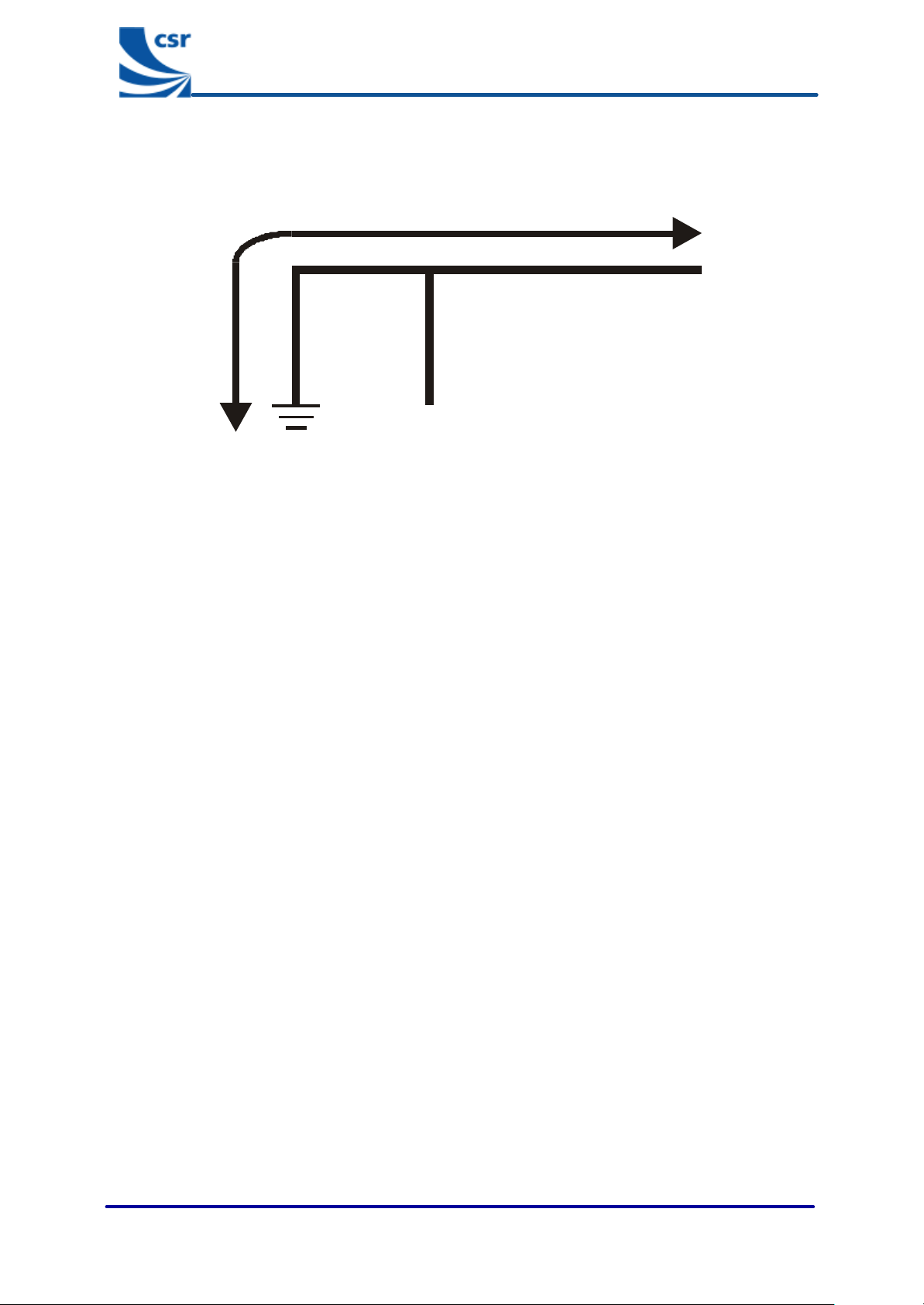
2 Inverted-F Antenna
Quarterwave
Input
Output
Figure 2.1: Inverted-F Antenna
The inverted-F is a quarterwave antenna. It is bent into an L-shape. The shorter side is connected to earth. The
longer side is left open circuit at the end. The feed point is located somewhere between the earth end and the
open end. The resulting structure resembles the letter F and possesses the properties of both a loop antenna due
to the circulating current from the feed point to ground and a whip antenna due to the open circuited straight
section.
In the PCB version the antenna is printed on the top layer and a ground plane is placed near the antenna on the
top layer. There must not be a ground plane underneath the antenna.
The aim is to make the quarterwave section resonate at midband frequency (which is 2441MHz for Bluetooth™).
The feed point (which is the input/output connection) is connected to the L-Shape at the point corresponding to
50Ω. Experiment with measurement to determine correct location for the feed point and length of this antenna.
™
bcant-an-001Pa
This material is subject to CSR’s non-disclosure agreement.
© Copyright CSR 2003
Page 4 of 14
Meander Line Antenna
BlueCore
Inverted-F and Meander Line Antennas
3 Meander Line Antenna
Smith Chart
Input
Output
S
Ground
Plane
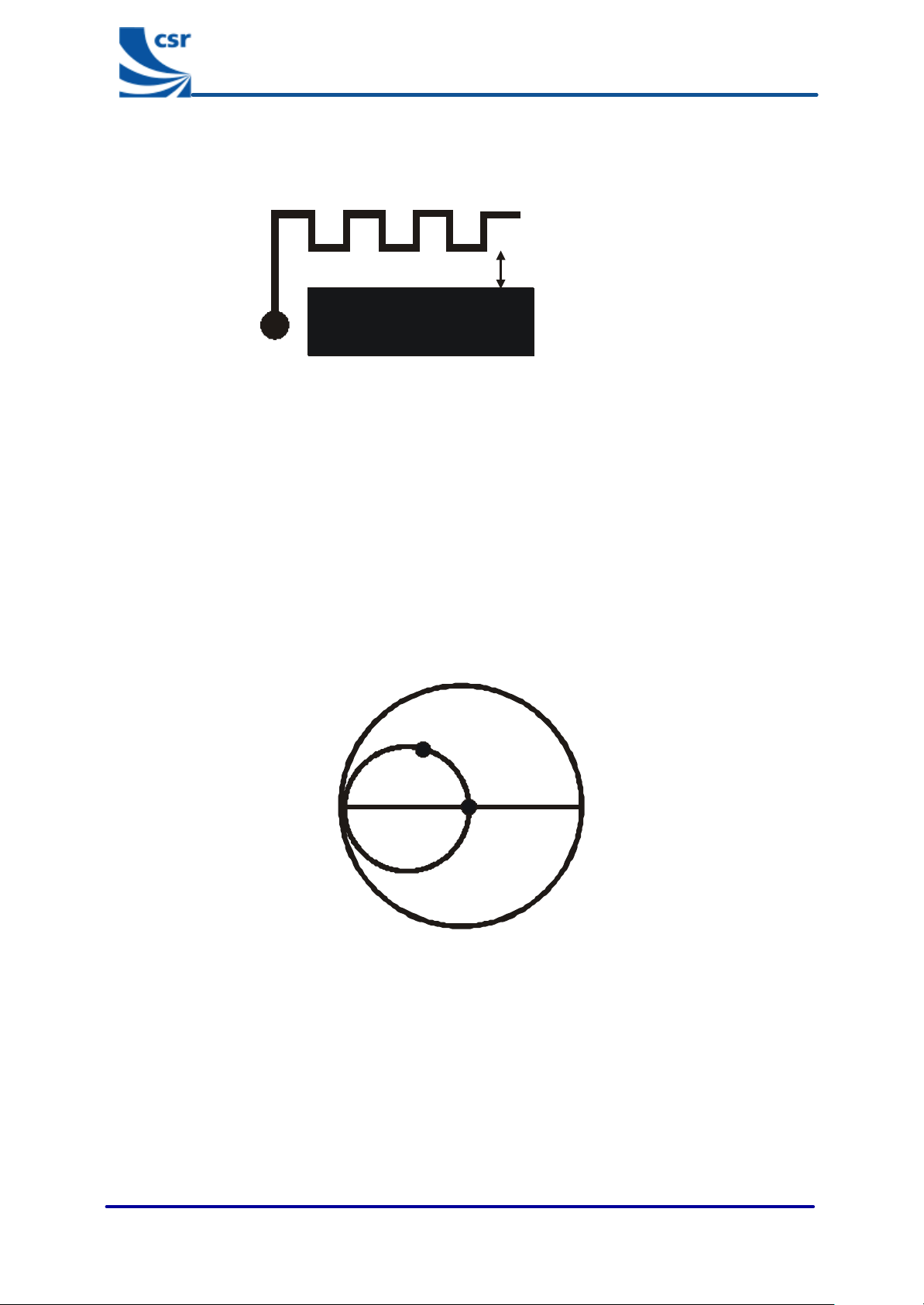
Figure 3.1: Meander Line Antenna
The length of the meander line antenna is difficult to predict. It is usually a bit longer than a quarterwave but
dependent on its exact geometry and proximity to the ground plane.
Note:
In Figure 3.1 the ground plane is shown in black. S is the distance from the ground plane. See Figure 4.2 for
approximate dimensions.
This type of antenna is always a PCB version. The antenna is printed on the top layer and a ground plane is
placed near the antenna on the top layer. There must be no ground plane underneath the radiating section of the
antenna.
A
B
™
The real part of the impedance of this antenna is about 15-25 Ω, depending on geometry and proximity to the
ground plane. The impedance matching is done by adjusting the length of the antenna until the input impedance
is at the unity conductance circle (when normalised to 50 Ω), in the top half of the Smith chart (Point A). A shunt
capacitor is then connected between the antenna input and ground to match to 50Ω (Point B). Experimental
measurement is used to determine the correct design.
bcant-an-001Pa
Figure 3.2: Input Impedance of Two Meander Line Antennas
© Copyright CSR 2003
This material is subject to CSR’s non-disclosure agreement.
Page 5 of 14

Real Designs
BlueCore
Inverted-F and Meander Line Antennas
4 Real Designs
5.0mm6.0m
m
8.0m
m
18.0mm
13.5mm
Width=0.8mm
Not to scale
Ground
Plane
Actual Size
Figure 4.1: Approximate Dimensions of Inverted-F Antenna
4.4mm1.0mm1.5mm
Width=0.5mm
2.8mm
1.7mm
Ground
1.5pF Capacitor
Placed immediately
after Feedpoint
Feedpoint
™
Not to scale
Plane
bcant-an-001Pa
Actual Size
Figure 4.2: Approximate Dimensions of Meander Line Antenna
© Copyright CSR 2003
This material is subject to CSR’s non-disclosure agreement.
Page 6 of 14

Proximity to Metal Objects
BlueCore
Inverted-F and Meander Line Antennas
5 Proximity to Metal Objects
CSR recommends keeping metal objects as far away from the antenna as possible. Keeping metallic objects out
of the near field is usually adequate.
Near Field = 2D2 / λ
D is the largest dimension of the antenna. In the case of these antennas, this is approximately a
quarterwave (λ /4).
Notes:
λ is the wavelength of the signal in freespace.
At Bluetooth frequencies, λ=122mm in freespace.
Substituting D=λ/4 into the Near Field equation gives Near Field = λ/8.
Near Field = 122/8 mm = 15.25mm.
™
bcant-an-001Pa
This material is subject to CSR’s non-disclosure agreement.
© Copyright CSR 2003
Page 7 of 14

Proximity to Dielectric Materials
BlueCore
Inverted-F and Meander Line Antennas
6 Proximity to Dielectric Materials
Dielectric materials (like plastic or FR-4) detune an antenna by lowering its resonant frequency. The effect is not
as serious as placing an antenna next to metal objects and can be corrected by reducing the length of the
antenna. Therefore it is important for the antenna to be tuned when it is in the product. This is done during the
development of the product.
™
bcant-an-001Pa
This material is subject to CSR’s non-disclosure agreement.
© Copyright CSR 2003
Page 8 of 14

Network Analyser
BlueCore
Inverted-F and Meander Line Antennas
7 Network Analyser
A Vector Network Analyser (VNA) is used to perform the initial tuning of the antenna:
1. The PCB track (trace), just before the antenna matching network is cut to isolate the filter and previous
stages from the measurement.
2. A coaxial cable is connected between the VNA and the PCB of the product. The outer conductor of the
coaxial cable is soldered to the ground plane of the PCB as close as possible to the input of the antenna
matching network. The inner conductor of the coaxial cable is left floating. The coaxial cable must have
ferrite beads over the outer sleeve of the coaxial cable. The ferrite beads help to prevent RF currents
from flowing on the outside of the coaxial cable (which would disturb the measurement).
3. A One-Port calibration is performed on the VNA with Open, Short, Loads connected at the end of the
coaxial cable inside the product.
4. The inner conductor of the coaxial cable is soldered to the input of the antenna matching network.
5. The antenna is tuned by adjusting the values of any “matching network” components, the feed point of
the antenna or the length of the antenna until the S11 trace (displayed on the VNA) is at the centre of
the Smith chart at the midband frequency 2441MHz.
6. The antenna is now roughly tuned and the cut track can be repaired by putting a small amount of solder
over the cut.
™
Figure 7.1: Preparation Before Measurement
Figure 7.2: Assembled System Ready to Measure
bcant-an-001Pa
This material is subject to CSR’s non-disclosure agreement.
© Copyright CSR 2003
Page 9 of 14

Final Tuning
BlueCore
Inverted-F and Meander Line Antennas
8 Final Tuning
After tuning the antenna using the VNA procedure, it is necessary to perform fine tuning. This will yield a small
improvement and will be the final optimisation of the antenna. It is best to perform this procedure in an anechoic
chamber, but when this is not possible an indoor or outdoor test range can be used. It is important to minimise
radio signal reflections. Avoid metallic objects such as lab-benches, filing cabinets, lampposts and cars.
Figure 8.1: Locating Product in Far Field of Antenna
™
bcant-an-001Pa
This material is subject to CSR’s non-disclosure agreement.
© Copyright CSR 2003
Page 10 of 14

Final Tuning
BlueCore
Inverted-F and Meander Line Antennas
Connect omni directional receive
antenna to a spectrum analyser
Place fully assembled Bluetooth product
approximately 2m away from receive antenna
Put Bluetooth product into continuous transmit
Watch power level of received signal on the specturm analyser while
moving receive antenna ±10cm in each of x,y,z planes to ensure it is not
located in a null point. A sudden dip in received power indicates a null point
Is antenna located in
Yes
Rotate Bluetooth product around in the x,y,z planes until the maximum
power level is observed on the spectrum analyser. This ensures that
the dominant polarisation mode of the antenna is measured.
a null point?
No
™
Has the maximum possible
No
power level been observed on
the spectrum analyser?
Yes
Record power level observed
on the spectrum analyser.
Turn off Bluetooth product, disassemble it
and make adjustments to length of antenna,
feed point or matching components
Reassemble Bluetooth product and place it in
the same location and orientation as before
Has the maximum receive
No
power been obtained?
Yes
End of procedure
bcant-an-001Pa
Repeat process on multiple devices
to ensure results are repeatable
Figure 8.2: Final Tuning Procedure
© Copyright CSR 2003
This material is subject to CSR’s non-disclosure agreement.
Page 11 of 14

Conclusion
BlueCore
Inverted-F and Meander Line Antennas
9 Conclusion
Metal objects should be kept at least 15.25mm away from the Inverted-F and Meander Line types of antennas in
the Bluetooth frequency band in order for the antenna to work efficiently. If that is not possible, then extra
experimentation is required to determine an acceptable trade-off between antenna performance and product size.
Even if these rules are followed, antenna detuning can occur. Usually the resonant frequency of the antenna will
be lowered. This can be corrected by reducing the length of the antenna.
™
bcant-an-001Pa
This material is subject to CSR’s non-disclosure agreement.
© Copyright CSR 2003
Page 12 of 14

Acronyms and Definitions
BlueCore
Inverted-F and Meander Line Antennas
Acronyms and Definitions
BlueCore Group term for CSR’s range of Bluetooth chips
Bluetooth Set of technologies providing audio and data transfer over short-range radio connections
CSR Cambridge Silicon Radio
PCB Printed Circuit Board
RF Radio Frequency
VNA Vector Network Analyser
™
bcant-an-001Pa
This material is subject to CSR’s non-disclosure agreement.
© Copyright CSR 2003
Page 13 of 14

Record of Changes
BlueCore
Inverted-F and Meander Line Antennas
Record of Changes
Date: Revision Reason for Change:
24 JAN 03 a Original publication of this document. (CSR reference bcant-an-001Pa).
BlueCore™
Inverted-F and Meander Line Antennas
™
Application Note
Bluetooth™ and the Bluetooth logos are trademarks owned by Bluetooth SIG Inc, USA and licensed to CSR.
BlueCore is a trademark of CSR.
All other product, service and company names are trademarks, registered trademarks or service marks of their
respective owners.
bcant-an-001Pa
January 2003
CSR’s products are not authorised for use in life-support or safety-critical applications.
bcant-an-001Pa
This material is subject to CSR’s non-disclosure agreement.
© Copyright CSR 2003
Page 14 of 14
 Loading...