

Page 1
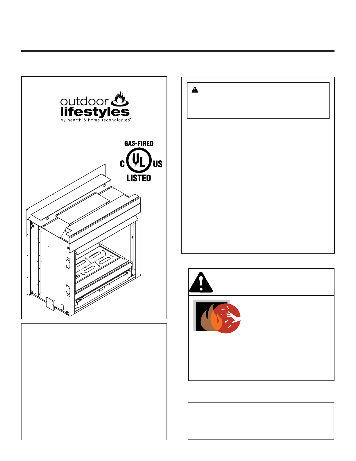
Installation Manual
Installation and Appliance Setup
INSTALLER: Leave this manual with party responsible for use and operation.
OWNER: Retain this manual for future reference.
NOTICE: DO NOT discard this manual!
Model:
TWILIGHT-II-MOD
WARNING: If the information in these
instructions is not followed exactly, a fi re
or explosion may result causing property
damage, personal injury, or death.
• DO NOT store or use gasoline or other fl am-
mable vapors and liquids in the vicinity of this
or any other appliance.
• What to do if you smell gas
- DO NOT try to light any appliance.
- DO NOT touch any electrical switch. DO
NOT use any phone in your building.
- Immediately call your gas supplier from a
neighbor’s phone. Follow the gas supplier’s instructions.
- If you cannot reach your gas supplier, call
the fi re department.
• Installation and service must be performed
by a qualifi ed installer, service agency, or the
gas supplier.
This appliance may be installed as an OEM
installation in manufactured home (USA
only) or mobile home and must be installed
in accordance with the manufacturer’s
instructions and the Manufactured Home
Construction and Safety Standard, Title 24
CFR, Part 3280 in the United States, or the
Standard for Installation in Mobile Homes,
CAN/CSA Z240 MH Series, in Canada.
This appliance is only for use with the type(s)
of gas indicated on the rating plate. This
appliance is not convertible for use with other
gases, unless a certifi ed kit is used.
Outdoor Lifestyles by Hearth & Home Technologies • Installation Manual TWILIGHT-II-MOD • 2290-970 Rev. F • 11/13
WARNING
HOT GLASS WILL
CAUSE BURNS.
DO NOT TOUCH GLASS
UNTIL COOLED.
NEVER ALLOW CHILDREN
TO TOUCH GLASS.
A barrier designed to reduce the risk of burns
from the hot viewing glass is provided with this
appliance and shall be installed.
In the Commonwealth of Massachusetts installation must be
performed by a licensed plumber or gas fi tter.
See Table of Contents for location of additional Commonwealth
of Massachusetts requirements.
1
Page 2

Safety Alert Key:
• DANGER! Indicates a hazardous situation which, if not avoided will result in death or serious injury.
• WARNING! Indicates a hazardous situation which, if not avoided could result in death or serious injury.
• CAUTION! Indicates a hazardous situation which, if not avoided, could result in minor or moderate injury.
• NOTICE: Used to address practices not related to personal injury.
Table of Contents
Installer Standard Work Checklist . . . . . . . . . . . . . . . . . . . . . . 3
1 Product Specifi c and Important Safety Information
A. Appliance Certifi cation . . . . . . . . . . . . . . . . . . . . . . . . . . . . 4
B. Glass Specifi cations . . . . . . . . . . . . . . . . . . . . . . . . . . . . . . 4
C. Thermal Performance Data . . . . . . . . . . . . . . . . . . . . . . . . 4
D. Air Infi ltration, Water Resistance and Structural Tests . . . 4
E. BTU Specifi cations . . . . . . . . . . . . . . . . . . . . . . . . . . . . . . . 4
F. High Altitude Installations . . . . . . . . . . . . . . . . . . . . . . . . . . 5
G. Non-Combustible Materials Specifi cation. . . . . . . . . . . . . . 5
H. Combustible Materials Specifi cation . . . . . . . . . . . . . . . . . 5
I. Electrical Codes . . . . . . . . . . . . . . . . . . . . . . . . . . . . . . . . . 5
J. Requirements for the Commonwealth of Massachusetts . . 6
2 Getting Started
A. Design and Installation Considerations . . . . . . . . . . . . . . . 7
B. Tools and Supplies Needed . . . . . . . . . . . . . . . . . . . . . . . . 7
C. Inspect Appliance and Components . . . . . . . . . . . . . . . . . . 7
3 Framing and Clearances
A. Appliance Dimension Diagram . . . . . . . . . . . . . . . . . . . . . . 8
B. Clearances to Combustibles . . . . . . . . . . . . . . . . . . . . . . . 9
4 Termination Location and Vent Information
A. Chimney Diagram. . . . . . . . . . . . . . . . . . . . . . . . . . . . . . . 11
8 Finishing
A. Facing Material . . . . . . . . . . . . . . . . . . . . . . . . . . . . . . . . . 22
B. Mantel and Wall Projections . . . . . . . . . . . . . . . . . . . . . . . 24
C. Door Dimensions for Finishing . . . . . . . . . . . . . . . . . . . . . 24
9 Appliance Setup
A. Fixed Glass Assembly . . . . . . . . . . . . . . . . . . . . . . . . . . . 25
B. Remove the Shipping Materials . . . . . . . . . . . . . . . . . . . . 26
C. Clean the Appliance . . . . . . . . . . . . . . . . . . . . . . . . . . . . . 26
D. Glass Refractory. . . . . . . . . . . . . . . . . . . . . . . . . . . . . . . . 26
E. Glass Rock Media Kit . . . . . . . . . . . . . . . . . . . . . . . . . . . . 27
F. Appliance Start Up . . . . . . . . . . . . . . . . . . . . . . . . . . . . . . 27
G. Install Trim and/or Surround . . . . . . . . . . . . . . . . . . . . . . . 27
10 Reference Materials
A. Accessories . . . . . . . . . . . . . . . . . . . . . . . . . . . . . . . . . . . 28
5 Appliance Preparation
A. Removing Non-combustible Facing Material Assembly . . 12
B. Securing and Leveling the Appliance . . . . . . . . . . . . . . . . 12
C. Installing Non-combustible Facing Material
(Outdoor Side) . . . . . . . . . . . . . . . . . . . . . . . . . . . . . . . . . 15
6 Electrical Information
A. General Information . . . . . . . . . . . . . . . . . . . . . . . . . . . . . 16
B. Wiring Requirements . . . . . . . . . . . . . . . . . . . . . . . . . . . . 18
7 Gas Information
A. Fuel Conversion . . . . . . . . . . . . . . . . . . . . . . . . . . . . . . . . 20
B. Gas Pressure . . . . . . . . . . . . . . . . . . . . . . . . . . . . . . . . . . 20
C. Gas Connection . . . . . . . . . . . . . . . . . . . . . . . . . . . . . . . . 20
D. High Altitude Installations . . . . . . . . . . . . . . . . . . . . . . . . . 21
E. Air Shutter Setting . . . . . . . . . . . . . . . . . . . . . . . . . . . . . . 21
Outdoor Lifestyles by Hearth & Home Technologies • Installation Manual TWILIGHT-II-MOD • 2290-970 Rev. F • 11/13 2
= Contains updated information.
Page 3
Installer Standard Work Checklist
Attention Installer: Follow this Standard Work Checklist
This standard work checklist is to be used by the installer in conjunction with, not instead of, the instructions contained in this
installation manual.
Customer:
Lot/Address:
Model (circle one): Twilight-II-MOD
Date Installed:
Location of Fireplace:
Installer:
Dealer/Distributor Phone #
Serial #:
WARNING! Risk of Fire or Explosion! Failure to install appliance according to these instructions can
lead to a fi re or explosion.
Appliance Install YES IF NO, WHY?
Required non-combustible board is installed. (Pg. 15) ___________________________
Verifi ed clearances to combustibles. (Pg. 9) ___________________________
Fireplace is leveled and secured. (Pg. 13) ___________________________
Electrical Section 6 (Pg 16-19)
Unswitched power (110-120 VAC) provided to the appliance. ___________________________
Switch wires properly installed. ___________________________
Gas Section 7 (Pg 20-21)
Proper appliance for fuel type. ___________________________
Was a conversion performed? ___________________________
Leak check performed and inlet pressure verifi ed. ___________________________
Verifi ed proper air shutter setting for installation type. ___________________________
Finishing Section 8 (Pg 22-24)
Combustible materials not installed in non-combustible areas. ___________________________
Verifi ed all clearances meet installation manual requirements. ___________________________
Mantels and wall projections comply with installation manual requirements. ___________________________
Appliance Setup Section 9 (Pg 25-27)
All packaging and protective materials removed (inside & outside of appliance). ___________________________
Refractories, logs, media and embers installed correctly. ___________________________
Glass assembly installed and secured. ___________________________
Accessories installed properly. ___________________________
Mesh, doors, or decorative front properly installed. ___________________________
Manual bag and all of its contents are removed from inside/under
the appliance and given to party responsible for use and operation. ___________________________
Started appliance and verifi ed no gas leaks exist. ___________________________
Hearth & Home Technologies recommends the following:
• Photographing the installation and copying this checklist for your fi le.
• That this checklist remain visible at all times on the appliance until the installation is complete.
Comments: Further description of the issues, who is responsible (Installer/ Builder/ Other Trades, etc) and corrective
action needed _____________________________________________________________________________________
_________________________________________________________________________________________________
_________________________________________________________________________________________________
_________________________________________________________________________________________________
Comments Communicated to party responsible ____________________ by ______________________on ___________
(Builder / Gen. Contractor/) (Installer) (Date)
Î = Contains updated information.
2290-972 1/13
Outdoor Lifestyles by Hearth & Home Technologies • Installation Manual TWILIGHT-II-MOD • 2290-970 Rev. F • 11/13
3
Page 4
1
1
Product Specifi c and Important Safety Information
A. Appliance Certifi cation
MODEL: TWILIGHT-II-MOD
LABORATORY: Underwriters Laboratories, Inc. (UL)
TYPE: Direct Vent Gas Appliance
STANDARD: ANSI Z21.50-2007/CSA 2.22-2007, Addenda
ANSI Z21.50a-2008/CSA 2.22a-2008, and
Addenda ANSI Z21.50b-2009/CSA 2.22b-2009
This product is listed to ANSI standards for “Vented Gas
Appliances” and applicable sections of “Gas Burning
Heating Appliances for Manufactured Homes and Recreational Vehicles”, and “Gas Fired Appliances for Use at
High Altitudes”.
NOTICE: This installation must conform with local codes.
In the absence of local codes you must comply with the
National Fuel Gas Code, ANSI Z223.1-latest edition in
the U.S.A. and the CAN/CGA B149 Installation Codes in
Canada.
NOT INTENDED FOR USE AS A PRIMARY HEAT SOURCE.
This appliance is tested and approved as either supplemental room heat or as a decorative appliance. It should not be
factored as primary heat in residential heating calculations.
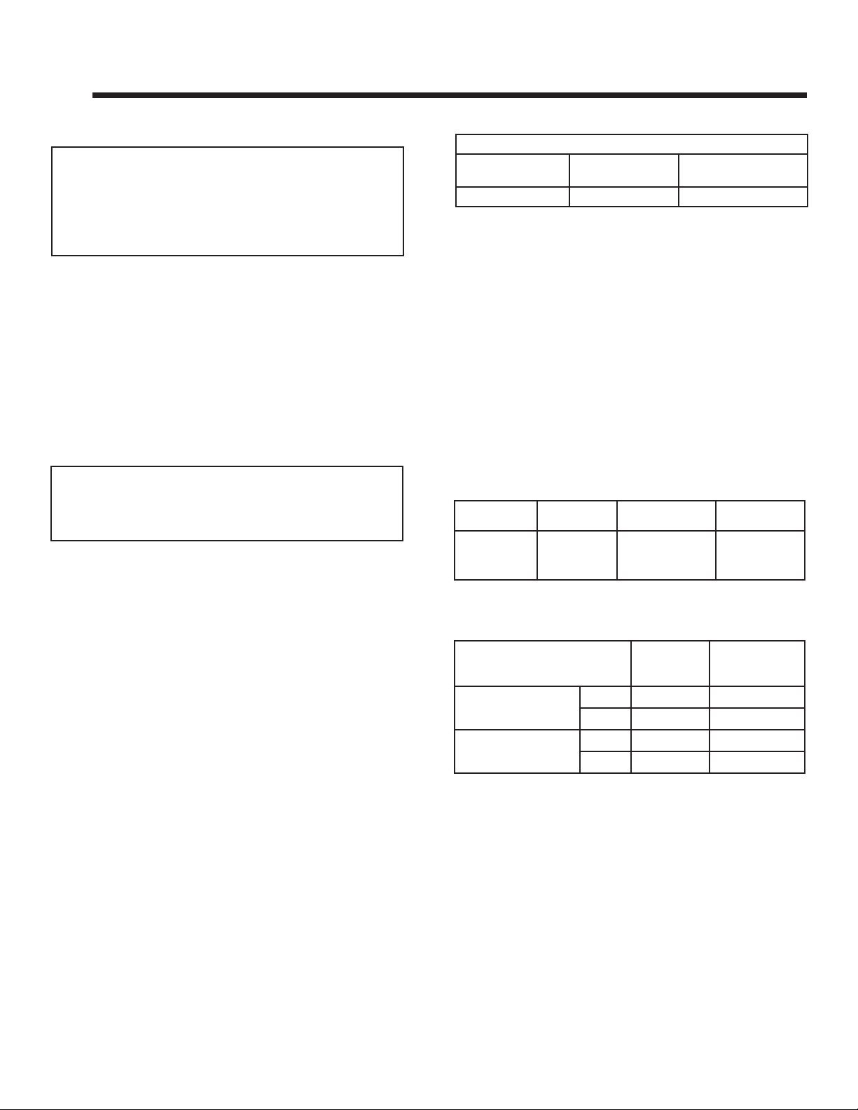
B. Glass Specifi cations
C. Thermal Performance Data
Model: TWILIGHT-II-MOD
Sound Transmission
Class (STC)
27 0.8hr-sq ft-ºF/BTU 1.25 BTU-in/hr-sq ft-ºF
Thermal Resistance
(R Value)
Thermal Conductivity
(K Value)
D. Air Infi ltration, Water Resistance and
Structural Tests
The Hearth & Home Technologies TWILIGHT-II-MOD Indoor/Outdoor Appliance unit was tested to the following
ASTM standards at the Stork Twin City Testing laboratory.
Air infi ltration test ASTM:E283-(04). The sample was test-
ed at 1.57 psf (equivalent to a 25-mph windload). Water
resistance test ASTM:E331-00. The test specimen was
tested at the requested test pressures of 8.0 & 25.0 psf.
Structural test ASTM:E330-02. The unit was tested to a
design pressure of 50-psf, a test pressure of 75-psf.
Test Results
Model
TWILIGHT-II-
MOD
Indoor/Outdoor
Air Infi ltration
(ASTM E283)
0.07CFM/ft2
Water Resistance
(ASTM E331)
No leakage
@ 8psf & 25psf
Structural Load
(ASTM E330)
No Blowout
@ 75psf
Tempered Glass (Interior Glass)
Hearth & Home Technologies appliances manufactured
with tempered glass may be installed in hazardous locations such as bathtub enclosures as defi ned by the
Consumer Product Safety Commission (CPSC). The
tempered glass has been tested and certifi ed to the re-
quirements of ANSI Z97.1 and CPSC 16 CFR 1202
(Safety Glazing Certifi cation Council SGCC# 1595 and
1597. Architectural Testing, Inc. Reports 02-31919.01
and 02-31917.01).
This statement is in compliance with CPSC 16 CFR Sec-
tion 1201.5 “Certifi cation and labeling requirements”
which refers to 15 U.S. Code (USC) 2063 stating “…Such
certifi cate shall accompany the product or shall otherwise
be furnished to any distributor or retailer to whom the
product is delivered.”
Some local building codes require the use of tempered
glass with permanent marking in such locations. Glass
meeting this requirement is available from the factory.
Please contact your dealer or distributor to order.
Ceramic Glass (Exterior Glass)
This appliance is equipped with 5 mm ceramic glass. Replace glass only with 5 mm ceramic glass. Please contact
your dealer for replacement glass.
E. BTU Specifi cations
Model
U.S. (0-2000 FT) or
Canada (2000-4500 FT)
TWILIGHT-II-MOD
(NG)
TWILIGHT-II-MOD
(LP)
US
CAN
US
CAN
Input
BTU/h
38,000 32
34,200 33
36,000 50
33,300 51
Orifi ce Size
(DMS)
Outdoor Lifestyles by Hearth & Home Technologies • Installation Manual TWILIGHT-II-MOD • 2290-970 Rev. F • 11/13 4
Page 5

F. High Altitude Installations
NOTICE: If the heating value of the gas has been reduced,
these rules do not apply. Check with your local gas utility
or authorities having jurisdiction.
When installing above 2000 feet elevation:
• In the USA: Reduce input rate 4% for each 1000 feet
above 2000 feet.
• In CANADA: Reduce input rate 10% for elevations
between 2000 feet and 4500 feet. Above 4500 feet,
consult local gas utility.
Check with your local gas utility to determine proper
orifi ce size.
G. Non-Combustible Materials Specifi cation
Material which will not ignite and burn. Such materials are
those consisting entirely of steel, iron, brick, tile, concrete,
slate, glass or plasters, or any combination thereof.
Materials that are reported as passing ASTM E 136,
Standard Test Method for Behavior of Materials in
a Vertical Tube Furnace at 750 ºC shall be considered
non-combustible materials.
H. Combustible Materials Specifi cation
Materials made of or surfaced with wood, compressed paper, plant fi bers, plastics, or other material that can ignite
and burn, whether fl ame proofed or not, or plastered or
unplastered shall be considered combustible materials.
I. Electrical Codes
NOTICE: This appliance must be electrically wired and
grounded in accordance with local codes or, in the absence
of local codes, with National Electric Code ANSI/NFPA
70-latest edition or the Canadian Electric Code CSA
C22.1.
• A 110-120 VAC circuit for this product must be protected
with ground-fault circuit-interrupter protection, in compliance
with the applicable electrical codes, when it is installed in
locations such as in bathrooms or near sinks.
Outdoor Lifestyles by Hearth & Home Technologies • Installation Manual TWILIGHT-II-MOD • 2290-970 Rev. F • 11/13
5
Page 6

Note: The following requirements reference various
Massachusetts and national codes not contained in this
document.
J. Requirements for the Commonwealth of
Massachusetts
For all side wall horizontally vented gas fueled equipment
installed in every dwelling, building or structure used in
whole or in part for residential purposes, including those
owned or operated by the Commonwealth and where the
side wall exhaust vent termination is less than seven (7)
feet above fi nished grade in the area of the venting, in-
cluding but not limited to decks and porches, the following
requirements shall be satisfi ed:
Installation of Carbon Monoxide Detectors
At the time of installation of the side wall horizontal vented
gas fueled equipment, the installing plumber or gas fi tter
shall observe that a hard wired carbon monoxide detector
with an alarm and battery back-up is installed on the fl oor
level where the gas equipment is to be installed. In addition, the installing plumber or gas fi tter shall observe that
a battery operated or hard wired carbon monoxide detector with an alarm is installed on each additional level of
the dwelling, building or structure served by the side wall
horizontal vented gas fueled equipment. It shall be the
responsibility of the property owner to secure the services
of qualifi ed licensed professionals for the installation of
hard wired carbon monoxide detectors.
In the event that the side wall horizontally vented gas fueled equipment is installed in a crawl space or an attic,
the hard wired carbon monoxide detector with alarm and
battery back-up may be installed on the next adjacent
fl oor level.
In the event that the requirements of this subdivision can
not be met at the time of completion of installation, the
owner shall have a period of thirty (30) days to comply
with the above requirements; provided, however, that during said thirty (30) day period, a battery operated carbon
monoxide detector with an alarm shall be installed.
Inspection
The state or local gas inspector of the side wall horizontally vented gas fueled equipment shall not approve the
installation unless, upon inspection, the inspector observes carbon monoxide detectors and signage installed
in accordance with the provisions of 248 CMR 5.08(2)(a)1
through 4.
Exemptions
The following equipment is exempt from 248 CMR 5.08(2)
(a)1 through 4:
• The equipment listed in Chapter 10 entitled “Equipment
Not Required To Be Vented” in the most current edition
of NFPA 54 as adopted by the Board; and
• Product Approved side wall horizontally vented gas fueled equipment installed in a room or structure separate
from the dwelling, building or structure used in whole or
in part for residential purposes.
MANUFACTURER REQUIREMENTS
Gas Equipment Venting System Provided
When the manufacturer of Product Approved side wall
horizontally vented gas equipment provides a venting
system design or venting system components with the
equipment, the instructions provided by the manufacturer
for installation of the equipment and the venting system
shall include:
• Detailed instructions for the installation of the venting
system design or the venting system components; and
• A complete parts list for the venting system design or
venting system.
Gas Equipment Venting System NOT Provided
When the manufacturer of a Product Approved side wall
horizontally vented gas fueled equipment does not provide the parts for venting the fl ue gases, but identifi es
“special venting systems”, the following requirements
shall be satisfi ed by the manufacturer:
Approved Carbon Monoxide Detectors
Each carbon monoxide detector as required in accordance with the above provisions shall comply with NFPA
720 and be ANSI/UL 2034 listed and IAS certifi ed.
Signage
A metal or plastic identifi cation plate shall be permanent-
ly mounted to the exterior of the building at a minimum
height of eight (8) feet above grade directly in line with the
exhaust vent terminal for the horizontally vented gas fueled heating appliance or equipment. The sign shall read,
in print size no less than one-half (1/2) in. in size, “GAS
VENT DIRECTLY BELOW. KEEP CLEAR OF ALL OBSTRUCTIONS”.
Outdoor Lifestyles by Hearth & Home Technologies • Installation Manual TWILIGHT-II-MOD • 2290-970 Rev. F • 11/13 6
• The referenced “special venting system” instructions
shall be included with the appliance or equipment installation instructions; and
• The “special venting systems” shall be Product Approved by the Board, and the instructions for that system shall include a parts list and detailed installation
instructions.
A copy of all installation instructions for all Product Approved side wall horizontally vented gas fueled equipment, all venting instructions, all parts lists for venting
instructions, and/or all venting design instructions shall
remain with the appliance or equipment at the completion
of the installation.
See Gas Connection section for additional Commonwealth of Massachusetts requirements.
Page 7
2
2
Getting Started
A. Design and Installation Considerations
Hearth & Home Technologies direct vent gas appliances
are designed to operate with all combustion air siphoned
from outside of the building and all exhaust gases expelled
to the outside. No additional outside air source is required.
The TWILIGHT-II-MOD has been carefully engineered to
provide a unique fi replace experience. Since it is different
than any other product on the market, care must be taken
when installing this appliance so that our customer does
not experience undesirable performance or conditions.
1. Install the appliance according to this Owner’s Guide
paying particular attention to fl ashing and sealing in-
structions.
2. In the cold northern climates pay attention to exposures and prevailing wind conditions when locating the
appliance, the same as you would for locating exterior
windows and doors.
The TWILIGHT-II-MOD has the thermal characteristics of a
high quality window system. Temperatures near the appliance will be cooler than what is realized with a fully insulated
wall.
Operation of the appliance will eliminate any cool drafts
and will provide the room with a comfortable ambiance.
Installation MUST comply with local, regional, state and
national codes and regulations. Consult insurance carrier,
local building inspector, fi re offi cials or authorities having
jurisdiction over restrictions, installation inspection and
permits.
Before installing, determine the following:
• Where the appliance is to be installed.
• Gas supply piping requirements.
• Electrical wiring requirements.
• Framing and fi nishing details.
• Whether optional accessories—devices such as a fan,
wall switch, or remote control—are desired.
Installation and service of this appliance should be
performed by qualifi ed personnel. Hearth & Home
Technologies suggests NFI certifi ed or factory
trained professionals, or technicians supervised by
an NFI certifi ed professional (www.nfi certifi ed.org).
Improper installation, adjustment, alteration, service or
maintenance can cause injury or property damage. For
assistance or additional information, consult a qualifi ed
service technician, service agency or your dealer.
Outdoor Lifestyles by Hearth & Home Technologies • Installation Manual TWILIGHT-II-MOD • 2290-970 Rev. F • 11/13
B. Tools and Supplies Needed
Before beginning the installation be sure that the following
tools and building supplies are available.
Tape measure Framing material
Pliers High temperature caulking material
Hammer Phillips screwdriver
Gloves Framing square
Voltmeter Electric drill and bits (1/4 in.)
Plumb line Safety glasses
Level Reciprocating saw
Manometer Flat blade screwdriver
Non-corrosive leak check solution
1/2 - 3/4 in. length, #6 or #8 Self-drilling screws
One 1/4 in. female connection (for optional fan).
C. Inspect Appliance and Components
• Carefully remove the appliance and components from
the packaging.
• The decorative doors and fronts may be shipped in
separate packages.
• Report to your dealer any parts damaged in shipment,
particularly the condition of the glass.
• Read all of the instructions before starting the instal-
lation. Follow these instructions carefully during the
installation to ensure maximum safety and benefi t.
WARNING! Risk of Fire or Explosion! Damaged parts
could impair safe operation. DO NOT install damaged, in-
complete or substitute components. Keep appliance dry.
Hearth & Home Technologies disclaims any responsibility for,
and the warranty will be voided by, the following actions:
• Installation and use of any damaged appliance or vent
system component.
• Modifi cation of the appliance or vent system.
• Installation other than as instructed by Hearth & Home
Technologies.
• Improper positioning of the gas logs or the glass door.
• Installation and/or use of any component part not approved
by Hearth & Home Technologies.
Any such action may cause a fi re hazard.
WARNING! Risk of Fire, Explosion or Electric Shock!
DO NOT use this appliance if any part has been under
water. Call a qualifi ed service technician to inspect the
appliance and to replace any part of the control system
and/or gas control which has been under water.
7
Page 8
3
3
Framing and Clearances
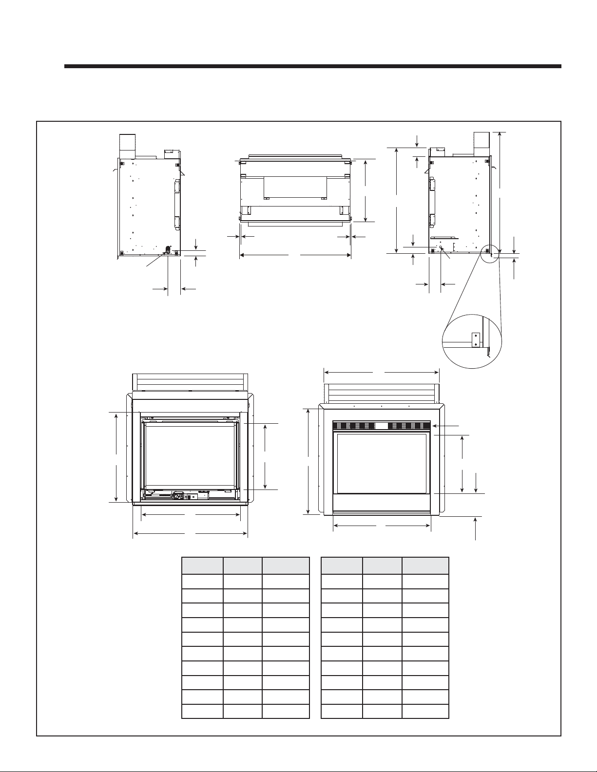
A. Appliance Dimension Diagram
Dimensions are actual appliance dimensions. Use for reference only.
OUTDOOR
H
E
G
F
OUTDOOR
K
GAS LINE
ACCESS
OUTDOOR
A
B
C
D
N
C
ELECTRICAL
ACCESS
I
J
P
VENT
OPENING
O
Q
S*
T
S* = MEASURE TO
BOTTOM OF LIP
AS SHOWN IN T
INDOOR VIEW
Figure 3.1 Appliance Dimensions
Outdoor Lifestyles by Hearth & Home Technologies • Installation Manual TWILIGHT-II-MOD • 2290-970 Rev. F • 11/13 8
L
R
M
OUTDOOR VIEW
Location Inches Millimeter Location Inches Millimeter
A 2-1/4 57 K 32-5/8 829
B 4-3/4 121 L 36-1/4 921
C 1/2 13 M 41-7/8 1064
D 43 1092 N 21-1/2 546
E 24 610 O 38-5/8 981
F 46-7/8 1191 P 42-1/8 1070
G 40-3/4 1035 Q 21-1/2 546
H 3-3/8 86 R 35-5/8 905
I 2-1/2 64 S 8 302
J 4-1/2 114 T 1-1/4 32
Page 9
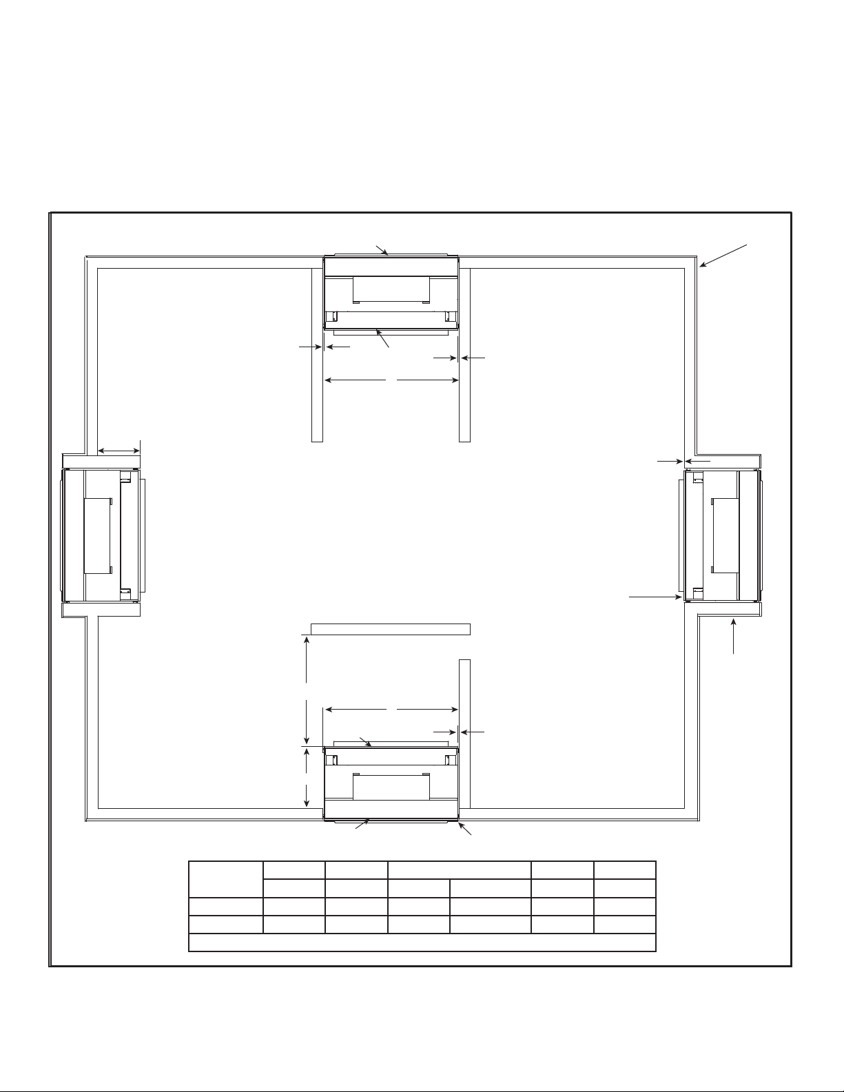
B. Clearances to Combustibles
GLASS
EXTERIOR INSULATED ENVELOPE
GLASS
A
B
B
D
C* = 24 INCH (MAX.)
B
GLASS
FLUSH TO EXTERIOR INSULATED ENVELOPE
GLASS
E
C*
NOTE: Appliance may be installed flush on exterior, interior
or anywhere in between. Any projection of the appliance
interior or exterior must have a properly constructed chase
surrounding the appliance. The exterior must have proper
insulating, flashing and finishing to ensure an insulated
envelope.
FLUSH TO INTERIOR
PROJECTION
C* = 0 INCH (MIN.)
WARNING! Risk of Fire! The exterior side of the TWILIGHT-II-MOD
CANNOT be recessed into the framing.
When selecting a location for the appliance it is important
to consider the required clearances to walls. See Figure
3.2.
WARNING! Risk of Fire or Burns! Provide adequate
clearance around air openings and for service access.
Due to high temperatures, the appliance should be located out of traffi c and away from furniture and draperies.
NOTICE: Illustrations refl ect typical installations and are
FOR DESIGN PURPOSES ONLY. Illustrations/diagrams
are not drawn to scale. Actual installation may vary due to
individual design preference.
WARNING! Risk of Fire! The exterior side of the
TWILIGHT-II-MOD CANNOT be recessed into the
framing.
Millimeters 1092 13 0 610 914 1092
Figure 3.2 Appliance Locations
AB C* DE
Minimum Minimum Minimum Maximum Minimum -
Inches 43 1/2 0 24 36 43
* = C dimension may be any length from 0 to 24 inches.
Outdoor Lifestyles by Hearth & Home Technologies • Installation Manual TWILIGHT-II-MOD • 2290-970 Rev. F • 11/13
9
Page 10

OVERHANG
A
A
B
SIDING
SIDING
SIDING
FINISHING MATERIALS
A
INTERIOR
FRAMING
EXTERIOR
FRAMING
E
D
C
A
B
NOTICE: Install appliance on hard metal or wood surfaces
extending full width and depth. DO NOT install directly
on carpeting, vinyl, tile or any combustible material other
than wood.
WARNING! Risk of Fire! Do not install appliance against
vapor barriers or exposed insulation. Prevent contact with
sagging or loose insulation.
• Locate and install appliance to all clearance specifi cations
in manual.
• The chase must be properly blocked to prevent blown
insulation or other combustibles from entering and
making contact with fi replace.
• Failure to maintain airspace may cause overheating and
a fi re.
• Reference Figure 3.2, Fgure 3.3 and Figure 3.4 for
clearance specifi cations.
Finishing Material Clearances
MINIMUM CLEARANCES
Vinyl Non-vinyl
A 36 in. 12 in.
B 64-5/16 in. 35-5/16 in.
Note: Framing dimensions assume use of
1/2 inch thick wall covering materials on
exterior of framing only, and NO sheetrock
on interior of framing.
Figure 3.4 Exterior View - Finishing Material Clearances
From top of hood to
ceiling (interior) or
overhang (exterior).
F
J
G
I
H
CLEARANCES TO COMBUSTIBLES:
Framing
for non-
combustible
material
Clearance
to Ceiling
(INTERIOR)
Clearance to Overhang
(EXTERIOR)
Non-Vinyl Vinyl
Combustible
Floor
Combustible
Flooring
Standoff
Height
Inside
Standoff
Height
Outside
Rough
Opening
(Depth)
Rough
Opening
(Width)
ABCD E F G H IJK
Exterior
Rough
Opening
(Height)
Interior
Rough
Opening
(Height)
Inches 47-5/8 41-1/4 23 44 46-1/8 35-3/4 35-5/16 64-5/16 0 0 3-3/8 9-1/2 1/2
mm 1210 1048 584 1118 1172 908 897 1634 0 0 86 241 13
Figure 3.3 Clearances to Combustibles
K
Outdoor Lifestyles by Hearth & Home Technologies • Installation Manual TWILIGHT-II-MOD • 2290-970 Rev. F • 11/13 10
Sides of
Appliance
Page 11

4
4
D
E
L
FP
A
H
M
X
J or K
I
A
G
F
FP
FP
FP
FP
FP
B
B
B
M
N
P
R
Q
FP
Termination Location and Vent Information
A. Chimney Diagram
= AREA WHERE APPLIANCE IS NOT PERMITTED
= AIR SUPPLY INLET
X
= APPLIANCE OPENING
FP
(See Note 2)
A = 0 in ........................clearances above grade, veran-
(See Note 1)
da, porch, deck or balcony
B* = 12 in. .....................clearances to window or door
that may be opened, or to permanently closed window.
D = 35-5/16 in. (
non-vinyl)
64-5/16 in. (vinyl) ......vertical clearance to ventilated
soffi t located above the hood
within a horizontal distance of 2
feet (60 cm) from the center-line
of the hood
E = 35-5/16 in.
(non-vinyl)
64-5/16 in. (vinyl).. ....clearance to unventilated soffi t
F = 9 in. ......................clearance to outside corner
G* = 12 in ......................clearance to inside corner
H = 3 ft. (Canada) ........not to be installed above a gas
meter/regulator assembly within
3 feet (90 cm) horizontally from
the center-line of the regulator
I = 3 ft. ........................clearance to service regulator
vent outlet and electric service
* 36 in. minimum for vinyl windows or vinyl siding.
** a appliance shall not open directly above a sidewalk or paved
driveway which is located between two single family dwellings
and serves both dwellings.
*** only permitted if veranda, porch, deck or balcony is fully open
on a minimum of 2 sides beneath the fl oor, or if the screened
porch guidelines are followed.
NOTE 1: Local codes or regulations may require different clearances.
NOTE 2: Termination in an alcove space (spaces open only on
one side and with an overhang) are permitted with the dimensions
specifi ed for vinyl or non-vinyl siding and soffi ts. 1. There must be 3
feet minimum between terminations or between the appliance and
termination. 2. All mechanical air intakes within 10 feet of a termination must be a minimum of 3 feet below the appliance hood. 3.
All gravity air intakes within 3 feet of the appliance hood must be a
minimum of 1 foot below the termination.
This appliance is approved for installation onto screened porches
with the following guidelines:
Figure 4.1 Minimum Clearances for Termination
Outdoor Lifestyles by Hearth & Home Technologies • Installation Manual TWILIGHT-II-MOD • 2290-970 Rev. F • 11/13
J = 9 in. (U.S.A.)
12 in. (Canada) .......clearance to non-mechani-
cal air supply inlet to building
or the combustion air inlet to
any other appliance
K = 3 ft. (U.S.A.)
6 ft. (Canada) ...........clearance to a mechanical
air supply inlet
L** = 54 in. .......................clearance above paved side-
(See Note 1)
walk or a paved driveway lo-
cated on public property
M*** = 35-5/16 in. ...............clearance under veranda,
porch, deck, balcony or over-
hang
64-5/16 in. ..............vinyl
N = 12 in. ......................non-vinyl siding
36 in. ......................vinyl siding
P = 8 ft.
Q
TWILIGHT-II-MOD 10 feet 2 x Q
1 additional terminations Q + 3 feet 1 x Q
2 additional terminations Q + 6 feet 2/3 x Q
3 additional terminations Q + 9 feet 1/2 x Q
R
= (2 / # caps plus appliance) x Q
MAX
MIN
ACTUAL
R
MAX
ACTUAL
ACTUAL
ACTUAL
ACTUAL
Minimum porch area: 96 square feet
Minimum ceiling height: 92 inches
Minimum two walls must be screened
Minimum top of screen height, side walls: 6 ft. 8 in.
Minimum screen area: 64 square feet
NOTE: There may be some odor and small amounts of
soot associated with venting the TWILIGHT-II-MOD onto a
screened porch. Ensuring good cross draft ventilation and
routine maintenance of the appliance will maximize comfort
and cleanliness.
11
Page 12

5
5
METAL HEARTH STRIP
UNDER EDGE OF
APPLIANCE
APPLY HIGH TEMPERATURE SEALANT
(300° F/149° C min.)
BOTH SIDES
Appliance Preparation
A. Removing Non-combustible Facing Ma-
terial Assembly
The non-combustible assembly is located on right-hand
side of appliance (when looking from outdoor side of
appliance).
CAUTION
Handle with care.
• Non-combustible material may be damaged if dropped.
• Hold non-combustible pieces in place.
• Remove and save two screws from upper bracket.
• Remove non-combustible pieces.
• Remove and save three screws from lower bracket.
• Discard brackets.
• Replace screws in holes where brackets were attached
to appliance.
CAUTION
Handle with care.
• Avoid damaging protruding edges on outdoor side of appliance.
B. Securing and Leveling the Appliance
Figure 5.1 Positioning the Metal Hearth Strip
APPLIANCE
EXTERIOR
WARNING
Fire Risk.
• Prevent contact with sagging, loose
insulation.
• Do NOT install against vapor barriers or
exposed insulation.
Placing Metal Hearth Strip
The metal hearth strip (approximately 46 inches x 4 inches)
is used to provide added protection where appliance and
outer structure meet.
• Place a generous bead of silicone caulk into the corner
of the protective hearth strip.
• Place the metal strip onto the structure where the outer
edge of the appliance will sit (see Figure 5.1). It should
overlap building paper to prevent water infi ltration.
Outdoor Lifestyles by Hearth & Home Technologies • Installation Manual TWILIGHT-II-MOD • 2290-970 Rev. F • 11/13 12
Page 13

FIREPLACE
FLANGE
APPLY HIGH
TEMPERATURE
SILICONE SEALANT
TO CORNER EDGES
BEND IN
FLANGE
Placing and Securing Appliance
Place the appliance into position. Make sure fl ashing edges
on the outdoor surround fi t up tight to the framing.
The diagram shows how to properly position, level, and
secure the appliance (see Figure 5.2). Nailing tabs are
provided to secure the appliance to the framing members.
• Caulk behind fl anges before securing to framing.
• Place the appliance into position.
• Level the appliance from side to side and front to back.
• Shim the appliance as necessary. It is acceptable to
use wood shims.
• Keep nailing tabs fl ush with the framing.
• Secure the appliance to the framing by using nails or
screws through the nailing tabs.
Figure 5.3 Application of High Temperature Sealant
Install outdoor fl ashing header (sheet metal piece removed
from shipping pallet). Place over upper portion of shroud
fl ange. Line up holes on shroud sides (see Figure 5.4).
SLIDE OUTDOOR FLASHING
DOWNWARD INTO POSITION
SECURE TO
FRAMING IN A MINIMUM
3 PLACES PER SIDE
NOTE: The exterior side of the appliance can protrude
outward. It MUST NOT be recessed into the framing. Caulk
behind all fl anges before securing to the exterior.
Figure 5.2 Proper Positioning, Leveling and Securing of Appliance
Do NOT notch into the framing around the appliance spacers.
APPLIANCE
EXTERIOR
CAUTION
SECURE TO
FRAMING
HEADER
FLASHING
(INSTALLED
CORRECTLY)
SCREW
LOCATIONS
Figure 5.4 Header Flashing Installation
Seal header fl ashing to exterior of building using high
temperature caulk. Attach to building using holes provided on the top of the left and right sides of outdoor fl ashing
(see Figure 5.4).
Placing Flashing and Sheathing
Apply high temperature silicone sealant to corner edges
of fi replace fl ange (see Figure 5.3).
Outdoor Lifestyles by Hearth & Home Technologies • Installation Manual TWILIGHT-II-MOD • 2290-970 Rev. F • 11/13
13
Page 14

Apply housewrap or building paper
APPLIANCE
TL-TRIM KIT
HOOD
TOP HOOD
TOP OF
FIREPLACE
16-5/16 in.
WALL STUD
HOUSEWRAP
INSULATION
HOUSEWRAP **
(BUILDING
PAPER) OVERLAP
FLASHING 1 in.
SHEATHING,
COMBUSTIBLE
FIREPLACE
HEADER
INSULATED
FRAMING
STANDOFF
NON-COMBUSTIBLE
*
SHEATHING
10-7/8 in.
FLASHING
HEADER
10-7/8 in.
= NON-COMBUSTIBLE ZONE
2-3/4 in.
2-3/4 in.
= SHEATHING
= 1 INCH HOUSEWRAP OVERLAP
FLASHING
SHEATHING
NON-COMBUSTIBLE ZONE
For placement of combustible housewrap or building paper and non-combustible sheathing for the outside wall
see Figures 5.5 and 5.6.
Special care should be taken when choosing building
materials for weatherproofi ng (i.e. building wraps, seal-
ant tapes, liquid sealants, rubberized fl ashings, etc.).
All sealant materials or building wraps installed within 6
inches of the top and 1 inch on the sides of the fi replace
surround must be approved to a minimum temperature
of 225ºF continuous exposure. Consult the material’s
manufacturer to ensure product compliance.
TOP OF SURROUND
METAL FLASHING
6 IN.
* NOTE: All fi nishing materials on top of exterior sheathing
must be non-combustible for a minimum of 10-7/8 inches
above and 2-3/4 inches on both sides of the exterior face of
the appliance. This non-combustible fi nishing material can
be up to a maximum of 6 inches thick (6 inches maximum
horizontal overhang) to allow for brick and stone alcoves
(see Figure 5.5).
** NOTE: Combustible house wrap or building paper MUST
NOT extend over the outside of non-combustible sheath-
ing, and MAY extend over the fl ashing behind non-com-
bustible sheathing a maximum of 1 inch. Use high temp
silicone or sealant recommended by the manufacturer of
the housewrap to seal between combustible sheathing
house wrap and non-combustible sheathing. The sealant
material used within 6 inches of the top and 1 inch on the
sides of the fi replace surround must be approved to a
minimum temperature of 225ºF continuous exposure.
Once the appliance is in place, use enough high temperature silicone sealant or manufacturer specifi ed sealant (ap-
proved to a minimum of 225ºF) to make a water tight seal
between outdoor surround and exterior sheathing.
Face the perimeter of the appliance with non-combustible
sheathing over shroud fl anges and fl ashing. See Figure
5.7 for non-combustible zone.
SIDE OF SURROUND
Figure 5.5 Outside View without Non-Combustible Sheathing Shown
Figure 5.6 Outside View Showing Non-Combustible Sheathing
Outdoor Lifestyles by Hearth & Home Technologies • Installation Manual TWILIGHT-II-MOD • 2290-970 Rev. F • 11/13 14
1 IN.
Figure 5.7 Exterior Installation Prior to Finishing
WARNING
Risk of Fire
• Non-combustible clearances must be maintained.
• Sheetrock, wood or other combustibles must
NOT be used as sheathing or facing in the noncombustible zone.
• See Sections 5 and 10 for proper clearances.
• See Section 1 for combustible /non-combusti-
ble defi nitions.
Page 15

C. Installing Non-combustible Facing Mate-
rial (Outdoor Side)
WARNING
Fire Risk.
• Follow these instructions exactly.
• Facing materials must be installed properly to
prevent fi re.
• No materials may be substituted
without authorization by Hearth & Home
Technologies.
• Center and attach two top boards (the two shorter pieces)
to the framing members. See Figure 5.8.
• Attach the left and right side pieces to the framing members. See Figure 5.9.
• Use fasteners from fastener packet (in manual bag) in
shaded areas. See Figure 5.9.
• Use regular sheet rock screws in shaded areas (noncombustible board.
NON-COMBUSTIBLE
FACING MATERIAL
48-5/8 in.
47-5/8 in.
Figure 5.9 Complete Installation of Non-combustible
Facing Material (Outdoor Side)
• Use a wet or dry towel or soft brush to remove dust or
dirt from facing material.
• Apply a non-combustible adhesive to attach tile, stone
or other non-combustible fi nishing materials per manu-
facturer’s instructions.
Apply fasteners from
fastener packet
in these areas.
Figure 5.8 Attaching Non-combustible Facing Material
(Outdoor Side Only)
Outdoor Lifestyles by Hearth & Home Technologies • Installation Manual TWILIGHT-II-MOD • 2290-970 Rev. F • 11/13
15
Page 16

6
6
GREEN WIRE
INSIDE BOX
14/2WG
COPPER GROUND
ATTACHED TO GRN SCREW
WITH GRN WIRE
BLK
WHT
WHT
BLK
HEAT SHIELD
Electrical Information
A. General Information
WARNING! Risk of Shock or Explosion! DO NOT wire
110-120VAC to the valve or to the appliance wall switch.
Incorrect wiring will damage controls.
NOTICE: This appliance must be electrically wired
and grounded in accordance with local codes or, in the
absence of local codes, with National Electric Code
ANSI/NFPA 70-latest edition or the Canadian Electric
Code CSA C22.1.
• Wire the appliance junction box to unswitched 110120 VAC. This is required for proper operation of the
appliance.
• A 110-120 VAC circuit for this product must be protected
with ground-fault circuit-interrupter protection, in
compliance with the applicable electrical codes, when
it is installed in locations such as in bathrooms or near
sinks.
• Low voltage and 110 VAC voltage cannot be shared
within the same wall box.
NOTICE: Waterproof insulated wire should be used when
wiring the junction box.
Junction Box Installation
If the box is being wired from the OUTSIDE of the appliance:
• Install the Romex™ connector (not included with
appliance) in the side wrap.
• Loosen two screws on the Romex connector, feed the
necessary length of wire through the connector and
tighten the screws.
• Make all necessary wire connections.
If the box is being wired from the INSIDE of the appliance:
• Remove the screw attaching the junction box to the
outer shell, rotate the junction box inward to disengage
it from the outer shell (see Figure 6.1).
• Pull the electrical wires from outside the appliance
through this opening into the valve compartment.
• Loosen the two screws on the Romex connector, feed
the necessary length of wire through the connector and
tighten the screws.
• Make all necessary wire connections to the receptacle
and assemble the receptacle and cover to the junction
box.
Outdoor Lifestyles by Hearth & Home Technologies • Installation Manual TWILIGHT-II-MOD • 2290-970 Rev. F • 11/13 16
NOTE: Do NOT wire
110 VAC to wall switch.
Figure 6.1 Junction Box Detail
Page 17

Optional Accessories
SEE DETAIL A
WIRE LEAD
2 FEMALE ENDS
PLUG AND WIRE
ASSEMBLY
JUNCTION BOX
6 FT.
APPROX.
TEMPERATURE
SENSOR SWITCH
FAN SPEED
CONTROL
(RHEOSTAT)
DETAIL A
WIRE LEAD
1 MALE END
1 FEMALE END
6 FT.
APPROX.
FAN KIT
#GFK-160T
Optional fan and remote control kits require that 110-120
VAC be wired to the factory installed junction box before
the appliance is permanently installed. See Figure 6.2.
Fan Installation
Fan should be positioned on the left side (as viewed from
appliance interior side. See Figure 6.3. NOTE: For ease
of installation, it is recommended that the fan be installed
prior to gas line installation.
Wall Switch
Position the wall switch in the desired position on a wall.
Run a maximum of 25 feet (7.8 m) or less length of 18
A.W.G. minimum wire and connect it to the appliance ON/
OFF switch pigtails.
APPLIANCE
LEFT SIDE
FAN
DRIP
TRAY
APPLIANCE INTERIOR SIDE
Figure 6.3 Fan location
Figure 6.2 Fan Wiring Diagram
Electrical Service and Repair
WARNING! Risk of Shock! Label all wires prior to disconnection when servicing controls. Wiring errors can
cause improper and dangerous operation. Verify proper
operation after servicing.
WARNING! Risk of Shock! Replace damaged wire with
type 105º C rated wire. Wire must have high temperature
insulation.
Outdoor Lifestyles by Hearth & Home Technologies • Installation Manual TWILIGHT-II-MOD • 2290-970 Rev. F • 11/13
NOTE: If any of the original wire as supplied
with the appliance must be replaced, it must be
replaced with the type 105oC rated wire.
17
Page 18

B. Wiring Requirements
Intellifi re Ignition System Wiring
• Wire the appliance junction box to 110-120 VAC for
proper operation of the appliance.
WARNING! Risk of Shock or Explosion! DO NOT wire
IPI controlled appliance junction box to a switched circuit.
Incorrect wiring will override IPI safety lockout.
• Refer to Figure 6.4, Intellifi re Pilot Ignition (IPI) Wiring
Diagram.
• This appliance is equipped with an Intellifi re control valve
which operates on a 3 volt system.
• Plug the 3-volt AC transformer into the appliance junction
box to supply power to the unit OR install two D cell
batteries (not included) into the battery pack before use.
NOTICE: Batteries should not be placed in the battery
pack while using the transformer. Remove batteries before
using the transformer, and unplug the transformer before
installing the batteries. Battery polarity must be correct or
module damage will occur.
PLUG-IN
3V TRANSFORMER
ON/OFF
WALL
SWITCH
FLAME SPARKER/
SENSOR
IGNITION
MODULE
(3V)
BRN
GROUND
PLUG IN
LOW VOLTAGE
SEE NOTE 1
REMOTE
CONTROL
TRANSFORMER
3 VAC
JUMPER WIRE
BLACK WIRE CAN BE
PLUGGED INTO ANY OF
#1 - #5 LOCATIONS
ON THE HOT SIDE
NEUTRAL
PIGGYBACK
ON/OFF SWITCH
VALV E
WHITE WIRE
CAN BE
PLUGGED
INTO ANY
OF #1-#5
LOCATIONS
ON THE
NEUTRAL SIDE
BRN
Note: To operate the appliance without a wall control
or remote control, connect the ON/OFF switch located
inside the control cavity of the appliance.
HOT
IGNITION MODULE
3 VAC
WIRE
ASSEMBLY
BRN
BRN
I
S
GROUND TO
FIREPLACE
CHASSIS
WHT
ORG
ORG
VALV E
INTERMITTENT
PILOT
IGNITOR
GRN
NOTE: 1. Ignition module, valve, pilot, and wall switch operate on 3 volts.
Uninterrupted 120 VAC is required at junction box unless equipped with battery back-up.
Figure 6.4 Intellifi re Pilot Ignition (IPI) Wiring Diagram
Outdoor Lifestyles by Hearth & Home Technologies • Installation Manual TWILIGHT-II-MOD • 2290-970 Rev. F • 11/13 18
Page 19

Connecting to the Appliance
WARNING
Wire 110-120VAC to electrical junction box.
Do NOT wire 110-120VAC to valve.
Do NOT wire 110-120VAC to wall switch.
• Incorrect wiring will damage millivolt valves.
• Incorrect wiring will override IPI safety lockout
and may cause explosion.
Note: To operate the appliance without a wall control
or remote control, connect the ON/OFF switch located
inside the control cavity of the appliance. See Figure 6.4.
• Keep wire lengths short as possible by removing any
excess wire length.
• Low voltage and 110-120 VAC voltage cannot be shared
within the same wall box.
Wall Switch Installation for Fan (Optional)
If the box is being wired to a wall mounted switch for use
with a fan (See Figure 6.5):
• The power supply for the appliance must be brought into
a switch box.
• The power can then be supplied from the switch box to
the appliance using a minimum of 14-3 with ground wire.
• At the switch box connect the black (hot) wire and red
(switch leg) wire to the wall switch as shown.
• At the appliance connect the black (hot), white (neutral)
and green (ground) wires to the junction box as shown.
• Add a 1/4 in. insulated female connector to the red
(switch leg) wire, route it through the knockout in the face
of the junction box, and connect to the top fan switch
connector (1/4 in. male) as shown.
Black
White
Green
Switch
Minimum 14-3 AWG
with Ground
Junction Box
Red
Black
White
Green
Red
Green
White
Black
Switch Box
Knockout
Red
Figure 6.5 Junction Box Wired to Wall Switch or BC10
Outdoor Lifestyles by Hearth & Home Technologies • Installation Manual TWILIGHT-II-MOD • 2290-970 Rev. F • 11/13
Power
Supply
Wires
19
Page 20

7
7
Gas Information
A. Fuel Conversion
• Make sure the appliance is compatible with available gas
types.
• Conversions must be made by a qualified service
technician using Hearth & Home Technologies specifi ed
and approved parts.
B. Gas Pressure
• Optimum appliance performance requires proper input
pressures.
• Gas line sizing requirements will be determined in ANSI
Z223.1 National Fuel Gas Code in the USA and CAN/
CGA B149 in Canada.
• Pressure requirements are:
Gas Pressure Natural Gas Propane
Minimum inlet pressure 5.0 in. w.c. 11.0 in. w.c.
Maximum inlet pressure 10.0 in. w.c. 13.0 in. w.c.
Manifold pressure 3.5 in. w.c. 10.0 in. w.c.
WARNING! Risk of Fire or Explosion! High pressure
will damage valve. Low pressure may cause explosion.
• Verify inlet pressures. Verify minimum pressures when
other household gas appliances are operating.
• Install regulator upstream of valve if line pressure is
greater than 1/2 psig.
WARNING
Fire Risk.
Explosion Hazard.
High pressure will damage valve.
• Disconnect gas supply piping BEFORE
pressure testing gas line at test pressures
above 1/2 psig.
• Close the manual shutoff valve BEFORE
pressure testing gas line at test pressures
equal to or less than 1/2 psig.
Note: Have the gas supply line installed in accordance with
local codes, if any. If not, follow ANSI 223.1. Installation
should be done by a qualifi ed installer approved and/or
licensed as required by the locality. (In the Commonwealth
of Massachusetts installation must be performed by a
licensed plumber or gas fi tter).
Note: A listed (and Commonwealth of Massachusetts approved) 1/2 in. (13 mm) T-handle manual shut-off valve
and fl exible gas connector are connected to the 1/2 in. (13
mm) control valve inlet.
• If substituting for these components, please consult
local codes for compliance.
C. Gas Connection
• Refer to Figure 3.1 for location of gas line access in
appliance.
• Gas line may be run through knockout(s) provided.
• The gap between supply piping and gas access hole
may be caulked with high temperature caulk or stuffed
with non-combustible, unfaced insulation to prevent cold
air infi ltration.
• Ensure that gas line does not come in contact with outer
wrap of the appliance. Follow local codes.
• Pipe incoming gas line into valve compartment.
Note: If installing optional fan, use factory-supplied fl ex
ball valve assembly to connect gas line to valve. Hardpipe connected directly to valve will not leave the amount
of space required for proper fan installation.
• Connect incoming gas line to the 1/2 in. (13 mm)
connection on manual shutoff valve.
WARNING! Risk of Fire or Explosion! Support control
when attaching pipe to prevent bending gas line.
• A small amount of air will be in the gas supply lines.
WARNING! Risk of Fire or Explosion! Gas build-up during line purge could ignite.
• Purge should be performed by qualified service
technician.
• Ensure adequate ventilation.
• Ensure there are no ignition sources such as sparks
or open fl ames.
Light the appliance. It will take a short time for air to purge
from lines. When purging is complete the appliance will
light and operate normally.
WARNING! Risk of Fire, Explosion or Asphyxiation!
Check all fi ttings and connections with a non-corrosive
commercially available leak-check solution. DO NOT use
open fl ame. Fittings and connections could have loos-
ened during shipping and handling.
WARNING! Risk of Fire! DO NOT change valve settings.
This valve has been preset at the factory.
Outdoor Lifestyles by Hearth & Home Technologies • Installation Manual TWILIGHT-II-MOD • 2290-970 Rev. F • 11/13 20
Page 21

D. High Altitude Installations
NOTICE: If the heating value of the gas has been reduced,
these rules do not apply. Check with your local gas utility
or authorities having jurisdiction.
When installing above 2000 feet elevation:
• In the USA: Reduce burner orifi ce 4% for each 1000 feet
above 2000 feet.
• In CANADA: Reduce burner orifi ce 10% for elevations
between 2000 feet and 4500 feet. Above 4500 feet,
consult local gas utility.
E. Air Shutter Setting
Air shutter settings should be adjusted by a qualifi ed ser-
vice technician at the time of installation. The air shutter
is set at the factory.
NOTICE: If sooting occurs, provide more air by opening
the air shutter.
Air Shutter Settings
NG LP
TWILIGHT-II-MOD 3/16 in. Full Open
Outdoor Lifestyles by Hearth & Home Technologies • Installation Manual TWILIGHT-II-MOD • 2290-970 Rev. F • 11/13
21
Page 22

8
8
41-7/8 in.
2-3/4 in.
NON-COMBUSTIBLE ZONE
OVERHANG
A
A
B
SIDING
SIDING
SIDING
FINISHING MATERIALS
A
Finishing
A. Facing Material
Inside Facing Material
• May install combustible materials up to specified
clearances on top, front and sides of appliance.
• Seal joints between fi nished wall and appliance top and
sides with 300ºF (140º C) minimum sealant.
• Leave space so bottom grille can be lowered for trim
door removal.
WARNING! Risk of Fire! DO NOT apply combustible
materials beyond the minimum clearances. Comply with
all minimum clearances to combustibles as specifi ed in
this manual. Overlapping materials could ignite and will
interfere with proper operation of doors and louvers.
WARNING
Risk of Fire
• Non-combustible clearances must be
maintained.
• Sheetrock, wood or other combustibles must NOT
be used as sheathing or facing in the noncombustible zone.
• See Sections 3 & 8 for proper clearances.
• See Section 1 for combustible/non-
combustible defi nitions.
May install non-combustible materials to cover gap between facing material and appliance (see Figure 8.3).
WARNING
Fire Risk.
Water Intrusion Risk.
Hood is required.
• Flashing and non-combustible sheathing must be
installed before facing materials.
• Facing must be non-combustible and seal tight to
fi replace front.
Figure 8.1 Non-combustible Zone (Interior)
Finishing Material Clearances
MINIMUM CLEARANCES
Vinyl Non-vinyl
A 36 in. 12 in.
B 64-5/16 in. 35-5/16 in.
WARNING
Fire Risk.
Finish all edges and fronts to clearances
and specifi cations listed in manual.
• Black metal columns may be covered with
non-combustible material only.
• Do NOT overlap combustible materials onto appliance
front.
• Install combustible materials only up to specified
clearances on top, front and side edges.
• Seal joints between the fi nished wall and appliance top
and sides using only a 300ºF minimum sealant.
Figure 8.2 Exterior View - Finishing Material Clearances
Outdoor Lifestyles by Hearth & Home Technologies • Installation Manual TWILIGHT-II-MOD • 2290-970 Rev. F • 11/13 22
Page 23

2-3/4 IN.
10-7/8 in.
HOOD
NON-COMBUSTIBLE
SHEATING
6 in.
MAX.
NON-COMBUSTIBLE
FACING
THERE MUST BE NO GAP
BETWEEN BRICK LEDGE,
FACING MATERIAL AND
APPLIANCE FRONT
6 in. MAXMUM PROJECTION
FROM FACE OF FIREPLACE
BRICK LEDGE
NON-COMBUSTIBLE
SHEATHING (SUPPLIED)
COMBUSTIBLE
SHEATHING
HOUSEWRAP
REQUIRED
FLASHING
(SUPPLIED)
HOUSE
WRAP
EXHAUST
FRESH AIR INTAKE
APPLIANCE
HOOD
TOP HOOD
TOP OF
FIREPLACE
10-7/8 in.
CEILING OR OVERHANG
64-5/16 in.
MINIMUM CLEARANCE
TO VINYL SOFFIT,
CEILING OR OVERHANG.
35-5/16 in.
MINIMUM CLEARANCE TO
NON-VINYL SOFFIT, MANTEL,
CEILING OR OVERHANG.
STUD WALL
SOFFIT
HOUSEWRAP
INSULATION
HOUSEWRAP
(BUILDING
PAPER) OVERLAP
FLASHING 1 in.
SHEATHING,
COMBUSTIBLE
FIREPLACE
HEADER
INSULATED
FRAMING
STANDOFF
NON-COMBUSTIBLE
SHEATHING
FLASHING
HEADER
Figure 8.3 Exterior View
NOTE: All fi nishing materials on top of exterior
sheathing must be non-combustible for a minimum
of 10-7/8 inches above and on both sides of
the exterior face of the appliance. This noncombustible fi nishing material can be up to a
maximum of 6 inches thick (6 inches maximum
horizontal overhang) to allow for brick and stone
alcoves. See Figure 8.5.
NOTE: Combustible housewrap or building
paper MUST NOT extend over the outside of
non-combustible sheathing, and MAY extend
over the fl ashing header behind non-combustible
sheathing. Use high temp caulk to seal between
combustible sheathing housewrap and noncombustible sheathing.
Figure 8.4 Exterior View
Outdoor Lifestyles by Hearth & Home Technologies • Installation Manual TWILIGHT-II-MOD • 2290-970 Rev. F • 11/13
23
Page 24

MEASURED
FROM CORNER
TOP VIEW
FIREPLACE
HOOD
1/2 IN.
APPLIANCE
HOOD
TOP OF
APPLIANCE
SOFFIT
SIDING
HOUSEWRAP (BUILDING
PAPER) AND SHEATHING
35-5/16 in.
MINIMUM CLEARANCE
TO NON-VINYL
64-5/16 in.
CLEARANCE TO VINYL
SOFFIT, OVERHANG, MANTEL,
OR CEILING
12 in.
MINIMUM CLEARANCE
TO NON-VINYL SIDING
36 in. MINIMUM
CLEARANCE TO VINYL SIDING
DRAIN PLANE
DETERMINED BY
LOCAL CODE
BRICK OR OTHER NON-COMBUSTIBLE
FACING MATERIAL 6 INCH MAXIMUM
PROJECTION FROM SURFACE OF
FIREPLACE (INCLUDES NON-COMBUSTIBLE
MANTEL PROJECTION)
NON-COMBUSTIBLE BRICK LEDGE
MUST BE TIGHT TO APPLIANCE
FACE OR NON-COMBUSTIBLE SHEATHING
TOP OF HOOD
INSULATION
DETAIL -
SEE FIGURE 10.5
Figure 8.5 Exterior View with Non-combustible Facing Material
B. Mantel and Wall Projections
WARNING! Risk of Fire! Comply with all minimum clearances as specifi ed. Framing closer than the minimums list-
ed must be constructed entirely of noncombustible materials (i.e., steel studs, concrete board, etc.) Failure to comply
could cause fi re.
NON-COMBUSTIBLE BOARD
(SUPPLIED ON APPLIANCE)
INDOOR SIDE ONLY
Figure 8.6 Clearances to a Combustible and/or Non-combustible
Indoor Mantel
Outdoor Lifestyles by Hearth & Home Technologies • Installation Manual TWILIGHT-II-MOD • 2290-970 Rev. F • 11/13 24
HOOD
MEASUREMENTS FROM
TOP EDGE O F THE OPENING
Note: Measurements are in inches.
11
10
9
8
7
6
8-5/8
7-5/8
12-5/8
11-5/8
10-5/8
9-5/8
CEILING
12
35-3/4
13-5/8
Figure 8.7 Clearances to a Combustible and/or Non-combustible
C. Door Dimensions for Finishing
Only doors certifi ed for use with this appliance model may
be used. Contact your dealer for a list of doors that may
be used.
Indoor Mantel or Mantel Leg
Page 25

9
9
GLASS RETAINER BRACKET
WING NUT ON THREADED STUD
Appliance Setup
A. Fixed Glass Assembly
WARNING! Risk of Asphyxiation! Handle fi xed glass
assembly with care. Inspect the gasket to ensure it is
undamaged and inspect the glass for cracks, chips or
scratches.
• DO NOT strike, slam or scratch glass.
• DO NOT operate fi replace with glass removed, cracked,
broken or scratched.
• Replace as a complete assembly.
Removing Fixed Glass Assembly- Interior
• Loosen two wing nuts on bottom glass retainer bracket.
• Loosen and remove two wing nuts on top glass retainer
bracket. Remove glass retainer bracket. See Figure 9.1
• Lift glass assembly off of glass retainer bracket.
Replacing Fixed Glass Assembly - Interior
• Position glass assembly on bottom glass retainer bracket.
Tighten wing nuts on bottom glass retainer bracket.
• Position top of glass assembly, position top glass retainer
bracket and secure with two wing nuts.
WING NUT LOCATIONS
9.1 Glass Assembly - Interior Side
GLASS RETAINER BRACKET
WING NUT ON THREADED STUD
9.2 Glass Assembly - Interior Side
Outdoor Lifestyles by Hearth & Home Technologies • Installation Manual TWILIGHT-II-MOD • 2290-970 Rev. F • 11/13
25
Page 26

GLASS LATCH
Removing Fixed Glass Assembly- Exterior
• Remove vanity panel from appliance to expose glass
latches.
• Pull glass latch out to release. Grasp glass assembly on
sides and pull bottom toward you. Slide glass assembly
down and out from under glass retainer.
GLASS RETAINER
GLASS LATCHES
B. Remove the Shipping Materials
Remove shipping materials from inside or underneath the
fi rebox.
C. Clean the Appliance
Clean/vacuum any sawdust that may have accumulated
inside the fi rebox or underneath in the control cavity.
D. Glass Refractory
Install black glass refractory panels by carefully sliding
them in between the fi rebox and glass retainer brackets.
See Figure 9.3
Note: Place the glass refractory so that the smooth, re-
fl ective side is facing the inside, or viewing area, of the
fi replace.
4.3 Glass Latch Locations - Exterior Side
GLASS LATCH
9.2 Glass Assembly - Exterior Side
Replacing Fixed Glass Assembly - Exterior
• Slide top of glass assembly into position under glass
retainer. Position bottom of glass assembly and secure
glass clips.
• Replace vanity panel.
USE SLOTS
TO SLIDE
REFRACTORY
INTO POSITION
Figure 9.3 Install Refractory
Outdoor Lifestyles by Hearth & Home Technologies • Installation Manual TWILIGHT-II-MOD • 2290-970 Rev. F • 11/13 26
Page 27

E. Glass Rock Media Kit
CORRECT
INCORRECT
WARNING! Choking Hazard! Keep glass rock media
out of reach of children.
CAUTION! Risk of Cuts, Abrasions or Flying Debris.
Wear protective gloves and safety glasses during installation. Sheet metal edges are sharp.
Cleaning the Glass Rock Media
During shipment of the glass rock media, dust and debris
can accumulate in the rock bag. It is recommended that
the glass rock media be rinsed thoroughly with water to remove dust and small glass rock particles. An easy method
to clean the glass rock media is to empty the contents of
the bag into a bucket and rinse thoroughly with a garden
hose. Allow the glass rock media to dry before installing
into the fi replace.
Installation
1. Place glass rock media evenly on base pan and over
top of burner. Do not block the open area by the glass
refractory. This area must remain open for proper air
fl ow. See Figure 9.4.
WARNING
WARNING! Risk of explosion! DO NOT place glass rock
media directly in front of the pilot assembly or between the
burner tracks over the burner ports. Improperly placed
media may interfere with proper burner operation.
Figure 9.5 Rock Placement Jig
CORRECT
NO MEDIA IN PILOT AREA
Delayed Ignition Risk
• Place glass rock media according to instructions.
• Do NOT place glass rock media in area in front
of pilot.
• Do NOT place glass rock media in a position that they may
fall into area in front of pilot.
• Do NOT use any media other than the glass rock media
supplied with this fi replace.
Fireplace will not function properly.
Delayed ignition may occur.
NOTICE: Care should be taken to avoid placing glass rock
media between the left and right of the media tray and the
fi rebox. Blocking this gap may cause an undesirable fl ame
appearance. See Figure 9.4.
NO MEDIA IN SHADED AREA
(BOTH LEFT AND RIGHT SIDE)
Figure 9.4 No Glass Rock Media in Gap
2. Remove the screw that holds the rock placement jig in
place. Carefully remove the rock jig, making sure that
no media falls into the pilot area.
Figure 9.6 CORRECT Media Placement
INCORRECT
MEDIA IN PILOT AREA NOT ALLOWED
Figure 9.7 INCORRECT Media Placement
F. Appliance Start Up
After appliance is completely set up, replace glass
assembly (assemblies). Start the appliance and perform
a leak check using a commercially available, noncorrosive
leak check solution. Be sure to rinse off all leak check
solution following testing. Extinguish the pilot and turn
the appliance off.
G. Install Trim and/or Surround
• Install optional trim kits and/or surrounds using the
instructions included with the accessory.
• Use non-combustible materials to cover the gap between
the sheet rock and the appliance (when applicable to the
model).
Outdoor Lifestyles by Hearth & Home Technologies • Installation Manual TWILIGHT-II-MOD • 2290-970 Rev. F • 11/13
27
Page 28

10
10
Reference Materials
A. Accessories
Install approved accessories per instructions included
with accessories. Contact your dealer for a list of approved accessories.
WARNING! Risk of Fire and Electric Shock! Use ONLY
Hearth & Home Technologies-approved optional accessories with this appliance. Using non-listed accessories
could result in a safety hazard and will void the warranty.
Remote Controls, Wall Controls and Wall
Switches
Follow the instructions supplied with the control installed
to operate your fi replace:
For safety:
• Install a switch lock or a wall/remote control with child
protection lockout feature.
• Keep remote controls out of reach of children.
See your dealer if you have questions.
Optional Fan
If desired, a fan kit may be added. Contact your dealer to
order the correct fan kit. Follow the instructions supplied
with the fan kit to operate your fan. See your dealer if you
have questions.
Decorative Doors and Fronts
WARNING! Risk of Fire! Install ONLY doors or fronts
approved by Hearth & Home Technologies. Unapproved
doors or fronts may cause fi replace to overheat.
This fireplace has been supplied with an integral
barrier to prevent direct contact with the fi xed glass
panel. DO NOT operate the fi replace with the barrier
removed.
Contact your dealer or Hearth & Home Technologies if
the barrier is not present or help is needed to properly
install one.
For more information refer to the instructions supplied with
your decorative door or front.
Please contact your Hearth & Home Technologies dealer with any questions or concerns.
For the location of your nearest Hearth & Home Technologies dealer, please visit www.hearthnhome.com.
Hearth & Home Technologies
7571 215th St, Lakeville, MN 55044
Printed in U.S.A. - Copyright 2013
Outdoor Lifestyles by Hearth & Home Technologies • Installation Manual TWILIGHT-II-MOD • 2290-970 Rev. F • 11/13 28
 Loading...