

Page 1
Model:
Twilight
WARNING: IF THE INFORMATION
IN THESE INSTRUCTIONS IS NOT
FOLLOWED EXACTL Y, A FIRE OR
EXPLOSION MAY RESULT CAUSING PROPERTY DAMAGE, PERSONAL INJURY, OR DEATH.
- Do not store or use gasoline or other flammable vapors and liquids in the vicinity of this
or any other appliance.
- What to do if you smell gas
• Do not try to light any appliance.
• Do not touch any electrical switch.
• Do not use any phone in your building.
• Immediately call your gas supplier from a
neighbor's phone. Follow the gas supplier's
instructions.
• If you cannot reach your gas supplier, call
the fire department.
- Installation and service must be performed by a
qualified installer, service agency, or the gas
supplier.
Installers Guide
Underwriters
Laboratories Listed
READ THIS MANUAL BEFORE INSTALLING OR
OPERATING THIS APPLIANCE. THIS INSTALLERS
GUIDE MUST BE LEFT WITH APPLIANCE FOR
FUTURE REFERENCE.
WARNING: IMPROPER INSTALLATION, ADJUSTMENT, ALTERATION,
SERVICE OR MAINTENANCE CAN
CAUSE INJUR Y OR PROPERTY DAMAGE. REFER TO THIS MANUAL. FOR
ASSISTANCE OR ADDITIONAL INFORMA TION CONSULT A QUALIFIED INSTALLER, SERVICE AGENCY, OR THE
GAS SUPPLIER.
1.This appliance may be installed in an aftermarket, permanently located, manufactured (mobile) home, where not prohibited
by local codes.
2.This appliance is only for use with the type
of gas indicated on the rating plate. This
appliance is not convertible for use with
other gases, unless a certified kit is used.
Printed in U.S.A. Copyright 2004,
Heat-N-Glo Lifestyle Products,
a brand of Hearth & Home Technologies Inc.
20802 Kensington Boulevard, Lakeville, MN 55044
This product is covered by one or more of the following patents: (United States) 4,112,913; 4,408,594; 4,422,426; 4,424,792; 4,520,791; 4,793,322;
4,852,548; 4,875,464; 5,000,162; 5,016,609; 5,076,254 5,191,877; 5,218,953; 5,328,356; 5,429,495; 5,452,708; 5,542,407; 5,613,487; (Australia)
543790; 586383; (Canada) 1,123,296; 1,297,746; 2,195,264; (Mexico) 97-0457; (New Zealand) 200265; or other U.S. and foreign patents pending.
Please contact your Heat-N-Glo Lifestyle Products dealer with
any questions or concerns. For the number of your nearest HeatN-Glo Lifestyle Products dealer, please call 1-888-427-3973.
1
674-900K 6/04
Page 2
SAFETY AND WARNING INFORMATION
READ and UNDERSTAND all instructions carefully
!
before starting the installation. FAILURE TO
FOLLOW these installation instructions may result
in a possible fire hazard and will void the warranty.
Prior to the first firing of the fireplace, READ the
!
Using Your Fireplace section of the Owners Guide.
DO NOT USE this appliance if any part has been
under water. Immediately CALL a qualified service
!
technician to inspect the unit and to replace any part
of the control system and any gas control which has
been under water.
THIS UNIT IS NOT FOR USE WITH SOLID FUEL.
!
Installation and repair should be PERFORMED by a
qualified service person. The appliance and venting
!
system should be INSPECTED before initial use
and at least annually by a professional service
person. More frequent cleaning may be required
due to excessive lint from carpeting, bedding
material, etc. It is IMPERATIVE that the unit’s
control compartment, burners, and circulating air
passageways BE KEPT CLEAN to provide for
adequate combustion and ventilation air.
This gas fireplace and vent assembly MUST be
!
vented directly to the outside and MUST NEVER be
attached to a chimney serving a separate solid fuel
burning appliance. Each gas appliance MUST USE
a separate vent system. Common vent systems are
PROHIBITED.
INSPECT the external exhaust vent on a regular
!
basis to make sure that no debris is interfering with
the air flow.
The glass door assembly MUST be in place and
!
sealed, and the trim door assembly MUST be in
place on the fireplace before the unit can be placed
into safe operation.
DO NOT OPERA TE this appliance with the glass
door removed, cracked, or broken. Replacement of
!
the glass door should be performed by a licensed
or qualified service person. DO NOT strike or slam
the glass door.
The glass door assembly SHALL ONLY be
!
replaced as a complete unit, as supplied by the gas
fireplace manufacturer. NO SUBSTITUTE material
may be used.
Always KEEP the appliance clear and free from
!
combustible materials, gasoline, and other
flammable vapors and liquids.
NEVER OBSTRUCT the flow of combustion and
!
ventilation air. Keep the front of the appliance
CLEAR of all obstacles and materials for servicing
and proper operations.
Due to the high temperature, the appliance should
be LOCATED out of traffic areas and away from
!
furniture and draperies. Clothing or flammable
material SHOULD NOT BE PLACED on or near the
appliance.
Children and adults should be ALERTED to the
!
hazards of high surface temperature and should
ST AY AWAY to avoid burns or clothing ignition.
Young children should be CAREFULL Y SUPERVISED
when they are in the same room as the appliance.
DO NOT USE abrasive cleaners on the glass door
!
assembly. DO NOT ATTEMPT to clean the glass
door when it is hot.
Turn off the gas before servicing this appliance. It is
!
recommended that a qualified service technician
perform an appliance check-up at the beginning of
each heating season.
Any safety screen or guard removed for servicing
!
must be replaced before operating this appliance.
DO NOT place furniture or any other combustible
!
household objects within 36 inches of the fireplace
front.
2
Page 3

TABLE OF CONTENTS
Safety and Warning Information ................................................. 2
u
Service Parts List ........................................................................ 4
Section 1: Approvals and Codes................................................ 7
Appliance Certification.................................................................... 7
Installation Codes ........................................................................... 7
High Altitude Installations ................................................................ 7
Section 2: Getting Started .......................................................... 8
Introducing the Heat-N-Glo Lifestyle Products Gas Fireplaces ..... 8
Pre-installation Preparation ............................................................ 8
Section 3: Installing the Fireplace ........................................... 10
Step 1 Locating the Fireplace .................................................. 10
Step 2 Framing the Fireplace................................................... 10
Step 3 Positioning, Leveling, and
Securing the Fireplace.................................................. 12
Step 4 The Gas Control System .............................................. 13
u
Step 5 The Gas Supply Line .................................................... 13
Step 6 Gas Pressure Requirements ....................................... 13
Step 7 Wiring the Fireplace...................................................... 14
Step 8 Finishing........................................................................ 15
Step 9 Installing Trim, Logs, and Ember Material .................... 15
Installing the Trim .......................................................... 15
Positioning the Logs ..................................................... 15
Shutter Settings ............................................................ 15
Glass Specifications ..................................................... 16
Placing the Ember Material........................................... 16
Step 10 Before Lighting the Fireplace........................................ 16
Step 11 Lighting the Fireplace.................................................... 16
After the Installation ...................................................................... 16
Section 4: Maintaining and Servicing Your Fireplace ......... 17
u = Contains updated information.
3
Page 4
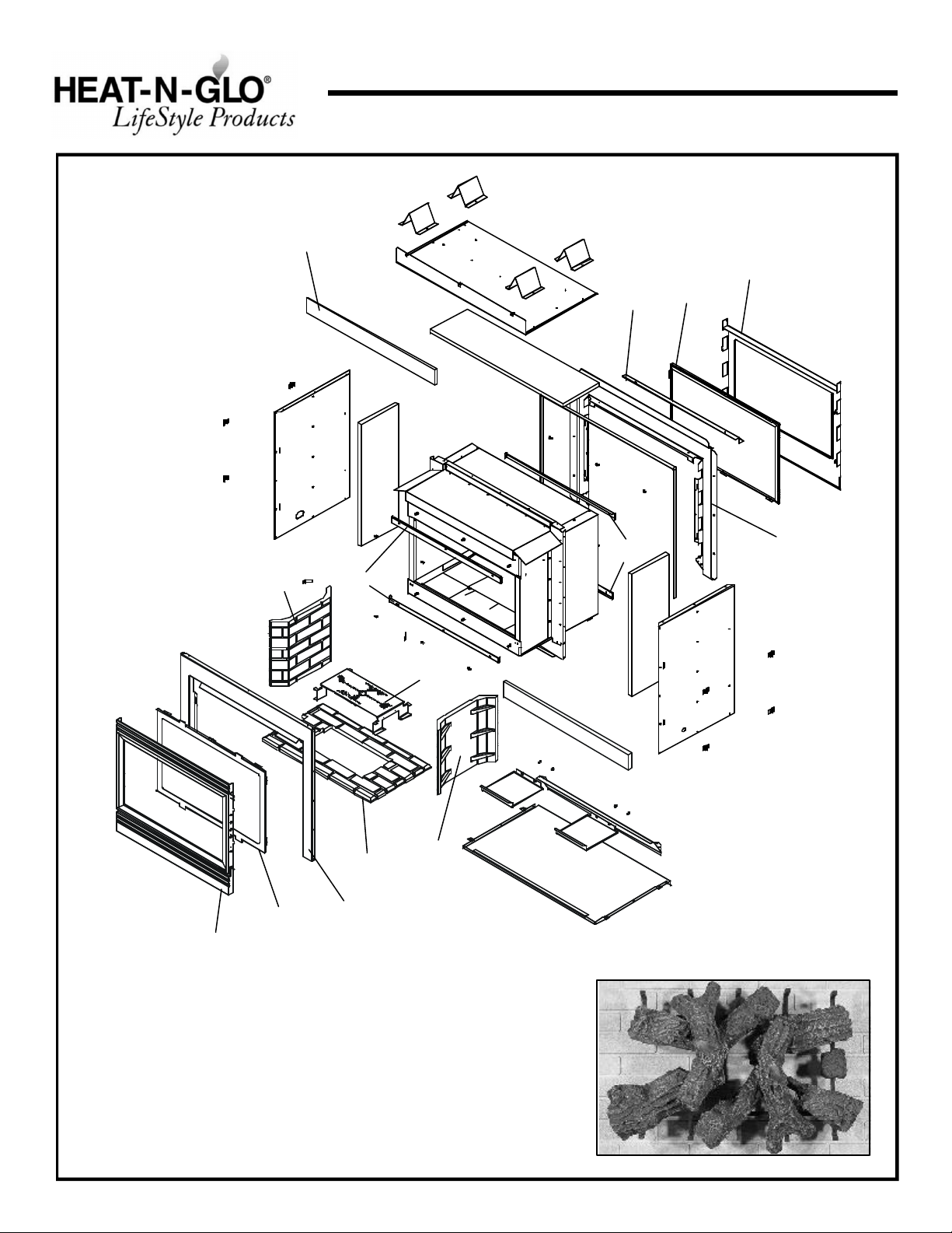
Service Parts
Twilight
(NG, LP) Exploded Parts Diagram
(GN, PL) Vue éclatée des pièces
12
11
Beginning Manufacturing Date: 8-01
Ending Manufacturing Date: ______
5
8
4
13
7
6
3
10
14
2
1
3
9 Log Set Assembly
Part number list on following page.
*
La liste des numéros de pièce se trouve à la page suivante.
*
4
Page 5

(NG, LP) Service Parts List / Liste des pièces de rechange
Twilight
IMPORTANT: THIS IS DATED INFORMA TION. The most current information is located on your dealers VIP site. When ordering,
supply serial and model numbers to ensure correct service parts. / IMPORTANT : L'information fournie dans cette brochure n'est
valide que pendant une courte période. Les sites VIP des distributeurs disposent des renseignements les plus récents. Lors
d'une commande, veuillez fournir les numéros de série et de modèles pour un remplacement adéquat des pièces.
ITEM /
PIÈCE
DESCRIPTION
SERIAL #
/ N° DE SÈRIE
PART #
/ N° DE PIÈCE
INTERMITTENT PILOT IGNITION PARTS / PARTIES D'IGNITION PILOTES INTERMITTENTES
1 Burner Assembly NG / Brûleur GN 674-176A
1 Burner Assembly LP / Brûleur PL 674-175A
2 Base Refractory / Base réfractaire SRV504-738-UM
3 Refractory, Side / Réfractaire, côté SRV504-737-UM
4 Outdoor Glass Assembly / Assemblée extérieure de verre GLA-OUTDOOR
5 Outdoor Door Assembly / Assemblée de Porte Extérieure 674-180
6 Indoor Glass Assembly / Assemblée de verre d'intérieur GLA-INDOOR
7 Indoor Door Assembly / Assemblée de Porte D'intérieur DF-36H
8 Hood / Hotte SRV674-174
9 Log Set Assembly (Sold as a Set Only) / Jeu de Bûches
PRE 002253964
POST 002253964
LOGS-MS
LOGS-TWILIGHT
10 Glass Clip Indoor / Agrafe de Verre D'intérieur 674-138
11 Glass Clip Outdoor / Agrafe de Verre Extérieure 674-137
u
u
12 Insulation Board / Conseil d'Isolation 674-452
13 Outside Surround / Entourez à l'extérieur 674-130
14 Inside Surround / Entourez à l'intérieur 674-131
Flashing Corner Cover / Projection de Couverture de Coin 674-169
Mesh Assembly / Écran MESH-36
ACCESSORIES / ACCESSOIRES
Remote Control Kit / Module de commande à distance RC-SMART-HNG
Remote Control Kit / Module de commande à distance SMART-STAT-HTL
Remote Control Kit / Module de commande à distance RC-SMART-HTL
Conversion Kit NG / Module de conversion GN NGK-STIO
Conversion Kit LP / Module de conversion PL LPK-STIO
Wall Switch Kit, Off-white / Interrupteur mural, blanc crème WSK-21-HTI
Wall Switch Kit, White / Interrupteur mural, blanc WSK-21-W-HTI
Spud LP / Pioche LP 446-517
u
Spud NG / Pioche NG 446-505
Also see following pages for additional valve assembly service part numbers.
5
Page 6
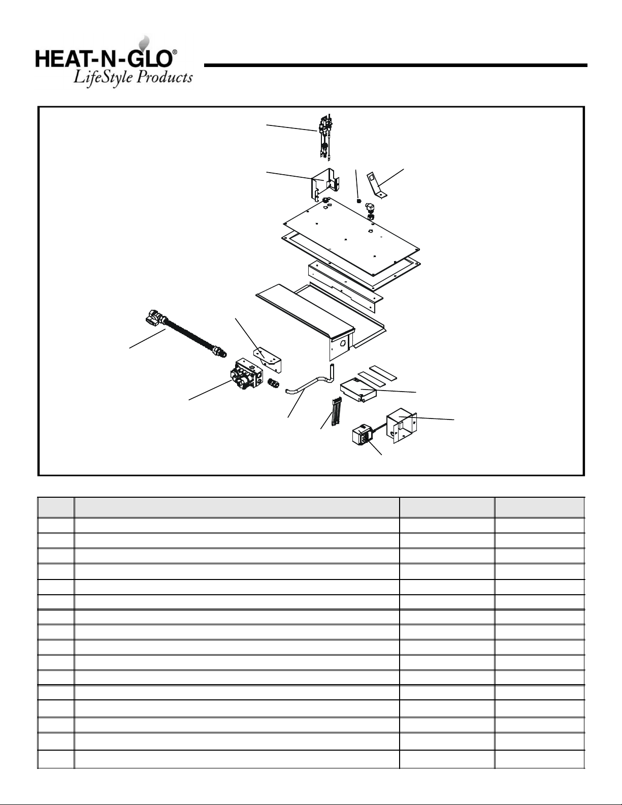
Service Parts
TWILIGHT
9
(NG, LP) Exploded Parts Diagram
(GN, PL) Vue éclatée des pièces
5
6
8
7
Beginning Manufacturing Date: 8-01
Ending Manufacturing Date: ______
12
2
11
3
4
1
10
ITEM /
PIÈCE
1 Junction Box / Boîtier de dérivation 100-250A
2 Valve NG (30 Sec) / Valve (30 Sec) GN 593-500
2 Valve LP (30 Sec) / Valve (30 Sec) PL 593-501
3 Flexible Gas Connector / Tuyau à gaz flexible 477-301A
4 Wire Assembly / Module de fil 593-590A
5 Pilot Assembly NG / Module de veilleuse GN 385-510A
5 Pilot Assembly LP / Module de veilleuse PL 385-511A
6 Pilot Bracket / Parenthèse Pilote 674-164
7 Burner Orifice (NG) (#31C) / Orifice de brûleur (GN) (#31C) 582-831
7 Burner Orifice (LP) (1.8mm) / Orifice de brûleur (PL) (1.8mm) 582-818
8 Valve Bracket / Parenthèse de Valve 674-167
9 Flex Ball Valve Assembly / Fléchir l'Assemblée de Soupape de Balle 302-320A
10 3V Adaptor / 3V Bouchon d'adapteur 593-593A
11 Control Module / Module de commande 593-592
12 Orifice Bracket / Parenthèse d'Orifice 674-110
DESCRIPTION
SERIAL #
/ N° DE SÉRIE
PART NUMBER
/ N° DE PIÈCE
u
Battery Pack / Paquet de Batterie(Pile) 593-594A
6
Page 7

1
Approvals and
Codes
Appliance Certification
The Heat-N-Glo Lifestyle Products fireplace models discussed in this Installers Guide have been tested to certification standards and listed by the applicable laboratories.
Certification
MODEL: Twilight
LABORATORY: Underwriters Laboratories
TYPE: Direct Vent Gas Fireplace
STANDARD: ANSI Z21.50•CGA2.22
ANSI Z21.50b-2000•CSA2.22b-2000
EXTERIOR WINDOW PERFORMANCE STANDARDS
LABORATORY: Stork Twin City Testing
STANDARD: ANSI/AAMA/NWWDA 101/I.S. 2-97
PERFORMANCE GRADES: F-R30* (45x37)
F-LC30* (45x37)
Air leakage does not exceed 0.3 cfm per square foot
at pressure differential of 1.57 lb per square foot per
ASTM E283-91.
The structural test pressure for wind loading
calculations exceeds the F-R/LC30 performance grade
withstanding design pressure of 50 lb per square foot
as tested per ASTM E330-96.
The Twilight has been carefully engineered to provide a
unique fireplace experience. Since it is different than any
other product on the market, care must be taken when
installing this fireplace so that our customer does not
experience undesirable performance or conditions.
1. Install the fireplace according to this Installer’s Guide
paying particular attention to flashing and sealing
instructions.
Installation Codes
The fireplace installation must conform to local codes. Before
installing the fireplace, consult the local building code
agency to ensure that you are in compliance with all
applicable codes, including permits and inspections.
In the absence of local codes, the fireplace installation must
conform to the National Fuel Gas Code ANSI Z223.1 (in
the United States) or the CAN/CGA-B149 Installation Codes
(in Canada). The appliance must be electrically grounded
in accordance with local codes or, in the absence of local
codes with the National Electric Code ANSI/NFPA No. 70
(in the United States), or to the CSA C22.1 Canadian Electric
Code (in Canada).
These models may be installed in a bedroom or bed-sitting
room in the U.S.A. and Canada.
High Altitude Installations
U.L. Listed gas appliances are tested and approved without requiring changes for elevations from 0 to 2,000 feet in
the U. S. A. and in Canada.
When installing this appliance at an elevation above 2,000
feet, it may be necessary to decrease the input rating by
changing the existing burner orifice to a smaller size. Input
rate should be reduced by 4% for each 1000 feet above a
2000 foot elevation in the U.S.A. or 10% for elevations
between 2000 and 4500 feet in Canada. If the heating value
of the gas has been reduced, these rules do not apply. To
identify the proper orifice size, check with the local gas
utility.
If installing this appliance at an elevation above 4,500 feet
(in Canada), check with local authorities.
2. In the cold northern climates pay attention to exposures
The Twilight has the thermal characteristics of a high quality
window system. Temperatures near the fireplace will be
cooler than what is realized with a fully insulated wall.
Operation of the fireplace will eliminate any cool drafts and
will provide the room with a comfortable ambiance.
and prevailing wind conditions when locating the fireplace,
the same as you would for locating exterior windows
and doors.
7
Page 8

2
Getting Started
Introducing the Heat-N-Glo Lifestyle
Products Gas Fireplaces
Heat-N-Glo Lifestyle Products direct vent gas fireplaces are
designed to operate with all combustion air siphoned from
outside of the building and all exhaust gases expelled to
the outside.
The information contained in this Installers Guide, unless
noted otherwise, applies to all models and gas control
systems. Gas fireplace diagrams, including the dimensions,
are shown in this section.
Pre-install Preparation
This gas fireplace and its components are tested and safe
when installed in accordance with this Installers Guide.
Report to your dealer any parts damaged in shipment,
particularly the condition of the glass. Do not install any
unit with damaged, incomplete, or substitute parts.
Read all of the instructions before starting the
installation. Follow these instructions carefully during
the installation to ensure maximum safety and benefit.
Failure to follow these instructions will void the
owner’s warranty and may present a fire hazard.
The Heat-N-Glo Lifestyle Products Warranty will be voided
by, and Heat-N-Glo Lifestyle Products disclaims any
responsibility for, the following actions:
• Installation of any damaged fireplace.
• Modification of the fireplace vent system.
• Installation other than as instructed by Heat-N-Glo
Lifestyle Products.
• Improper positioning of the gas logs or the glass door.
• Installation and/or use of any component part not manufactured and approved by Heat-N-Glo Lifestyle Products,
not withstanding any independent testing laboratory or
other party approval of such component part or accessory.
ANY SUCH ACTION MAY POSSIBLY CAUSE A FIRE
HAZARD.
When planning a fireplace installation, it’s necessary to
determine:
• Where the unit is to be installed.
• Gas supply piping.
• Electrical wiring.
• Framing and finishing details.
• Whether optional accessories—devices such as a wall
switch or remote control—are desired.
If the fireplace is to be installed on carpeting or tile, or on
any combustible material other than wood flooring, the
fireplace should be installed on a metal or wood panel that
extends the full width and depth of the fireplace.
8
Page 9

(2)
77
42
1068
42-1/2
24-1/8
8
204
36-1/8
40-1/2
36-3/8
1030[ ]
40-3/4
1034[ ]
(4)
1080[ ]
[ ]
43
1093[ ]
23-3/8
595[ ]
1/2
(8)
17-7/8
453[ ]
611[ ]
13[ ]
924[ ]
GAS LINE
ACCESS
8
204[ ]
77[ ]
3
917.7[ ]
TOP STANDOFFS
[ ]
3
[ ]
ELECTRICAL
ACCESS
INDOOROUTDOOR
TOP GRILLE
GLASS DOOR
BOTTOM
GRILLE
GAS CONTROLS
AND LABELS
GAS LINE
ACCESS
Figure 1.
Diagram of the Twilight (Dimensions in brackets are millimeters).
9
ELECTRICAL
ACCESS
Page 10

3
Installing the Fireplace
36”1”GLASS
FLUSH TO OUTSIDE
GLASS
41 1/4
[1047.8]
22 7/8
In cold northern climates pay attention to exposures and
prevailing wind conditions when locating the fireplace, the same
as you would for locating exterior windows and doors.
The Twilight has the thermal characteristics of a high quality
window system. Temperatures near the fireplace will be
cooler than what is realized with a fully insulated wall.
Step 1. Locating the Fireplace
The diagram below shows space and clearance requirements for locating a fireplace within a room. THE FIRE-
PLACE MUST BE LOCA TED FLUSH WITH THE OUTSIDE
OF AN EXTERIOR WALL!
Indoor Minimum Clearances
from the Fireplace to Combustible Materials
Inches mm
Glass............................... 36....................914
Floor ................................. 0....................... 0
Metal Sides ......................1/2 ....................13
Top ................................ 4 1/2.................. 114
Ceiling* ............................ 31....................787
* The clearance to the ceiling is measured from the top
of the unit, excluding the standoffs (see Figure 9).
The distance from the unit to combustible construction is to
be measured from the unit outer wrap surface to the combustible construction, NOT from the screw heads that secure the unit together.
Step 2. Framing the Fireplace
Fireplace framing can be built before or after the fireplace is
set in place. Framing should be positioned to accommodate wall coverings and fireplace facing material. The dia-
gram below shows framing reference dimensions.
CAUTION: MEASURE FIREPLACE DIMENSIONS AND
VERIFY FRAMING METHODS AND WALL COVERING
DETAILS BEFORE FRAMING.
Figure 2. Fireplace Dimensions and Locations
Clearance Requirements
The top and sides of the fireplace are defined by stand-offs.
The minimum clearance for the indoor side to a perpendicular
wall extending past the face of the fireplace is one inch (25
mm). The metal ends of the fireplace may NOT be recessed
into combustible construction.
WARNING: TO PREVENT CONTACT WITH
!
SAGGING OR LOOSE INSULATION, THE
FIREPLACE MUST NOT BE INSTALLED AGAINST
VAPOR BARRIERS OR EXPOSED INSULATION. LOCALIZED OVERHEATING COULD OCCUR AND A
FIRE COULD RESULT.
Outdoor Minimum Clearances
from the Fireplace to Combustible Materials
Inches mm
Glass............................... 36.................... 914
Floor ................................. 0 ......................0
Sides* .............................. 12 .................... 305
Top* ................................. 12.................... 305
Overhang (non-vinyl) .......... 31.................... 787
Overhang (vinyl) ................ 60................... 1524
*NOTE: Clearance to sides and top are 36” when vinyl siding is used.
WARNING: FRAMING DIMENSIONS ASSUME
!
USE OF 1/2 INCH THICK WALL COVERING
MATERIALS ON EXTERIOR OF FRAMING ONL Y AND
NO SHEETROCK ON INTERIOR OF FRAMING.
Framing should be
constructed of 2 X 4
lumber or heavier.
[581]
44
[1117.6]
Figure 3.
Framing Dimensions
10
Page 11

O
Q
FP
AHM
X
J or K
I
A
G
FP
B
P
FP
R
N
D
E
(See Note 2)
L
B
B
= FIREPLACE OPENING
V
FP
F
FP
X
FP
FP
= AIR SUPPLY INLET = AREA WHERE FIREPLACE IS NOT PERMITTED
A = 0" ............................ clearances above grade, veran-
(See Note 1)
da, porch, deck or balcony
B* = 12".......................... clearances to window or door
that may be opened, or to permanently closed window.
D** = 31".......................... vertical clearance to ventilated
soffit located above the terminal
within a horizontal distance of 2
feet (60 cm) from the center-line
of the terminal
E** = 31".......................... clearance to unventilated soffit
F = 9" ........................... clearance to outside corner
G* = 12".......................... clearance to inside corner
H = 3 ft. (Canada) ....... not to be installed above a gas
meter/regulator assembly within
3 feet (90cm) horizontally from the
center-line of the regulator
I = 3 ft. (U.S.A.)
6 ft. (Canada) ....... clearance to service regulator
vent outlet and electric service
* 36” minimum for vinyl windows or vinyl siding.
** 60” minimum for vinyl clad soffits.
*** a fireplace shall not open directly above a sidewalk or paved
driveway which is located between two single family dwellings
and serves both dwellings.
**** only permitted if veranda, porch, deck or balcony is fully open
on a minimum of 2 sides beneath the floor, or if the screened
porch guidelines are followed.
NOTE 1: Local codes or regulations may require different clearances.
NOTE 2: Termination in an alcove space (spaces open only on one
side and with an overhang) are permitted with the dimensions specified
for vinyl or non-vinyl siding and soffits. 1. There must be 3 feet minimum
between terminations or between the fireplace and termination. 2. All
mechanical air intakes within 10 feet of a termination must be a minimum
of 3 feet below the fireplace hood. 3. All gravity air intakes within 3
feet of the fireplace hood must be a minimum of 1 foot below the
termination.
Figure 4. Fireplace Opening Minimum Clearances
J = 9" (U.S.A.)
12" (Canada) ......... clearance to non-mechani-
cal air supply inlet to building or the combustion air inlet to any other appliance
K = 3 ft. (U.S.A.)
6 ft. (Canada) .......... clearance to a mechanical
air supply inlet
L*** = 54” ............................ clearance above paved
(See Note 1)
sidewalk or a paved driveway
located on public property
M****= 31"............................ clearance under veranda,
porch, deck or balcony
N = 12” ............................ non-vinyl siding
36” ............................ vinyl siding
O = 31” ............................ non-vinyl soffit and overhang
60” ............................ vinyl soffit and overhang
P = 8 ft.
Q
MIN
Twilight 10 feet 2 x Q
___________________________________________________________________________
1 additional termination cap Q + 3 feet 1 x Q
___________________________________________________________________________
2 additional termination caps Q + 6 feet 2/3 x Q
___________________________________________________________________________
3 additional termination caps Q + 9 feet 1/2 x Q
R
= (2 / # caps plus fireplace) x Q
MAX
This fireplace is approved for installation onto screened porches
with the following guidelines:
Minimum porch area: 96 square feet
Minimum ceiling height: 92 inches
Minimum of two walls must be screened
Minimum top of screen height, side walls: 6 ft. 8 in.
Minimum screen area: 64 square feet
NOTE: There may be some odor and small amounts of soot
associated with venting the Twilight onto a screened porch.
Ensuring good cross draft ventilation and routine maintenance
of the fireplace will maximize comfort and cleanliness.
ACTUAL
R
MAX
ACTUAL
ACTUAL
ACTUAL
ACTUAL
CAUTION: IF EXTERIOR WALLS ARE FINISHED WITH VINYL SIDING, IT IS NECESSARY TO INSTALL THE VINYL PROTECT OR
KIT TO THE TOP OF THE EXTERIOR FIRESTOP (FOR ALL ROUND TERMINATION CAPS). IT IS STRONGLY RECOMMENDED
WHENEVER POSSIBLE TO USE THE VINYL PROTECT OR KIT.
11
Page 12

Step 3. Positioning, Leveling, and
FLASHING
COVER (2)
BEND IN
FIREPLACE
HOUSEWRAP
SHEATHING
NON-COMBUSTIBLE
COMBUSTIBLE HOUSEWRAP
OUTSIDE
TO FRAMING
Securing the Fireplace
The diagram below shows how to properly position, level,
and secure the fireplace. Before the framing or fireplace is
set in place, the cutout should be covered with tar paper or
similar material.
The outdoor side of the fireplace contains edges that protrude
beyond the normal envelope of the fireplace. Special care
should be taken to avoid damage to these parts.
SECURE
IN A MINIMUM
3 PLACES
PER SIDE
• Level the fireplace from side to side and front to back.
• Shim the fireplace with non-combustible material, such
as sheet metal, as necessary.
• Secure the fireplace to the framing by using nails or screws
through the nailing tabs.
• See Figure 7 for placement of combustible housewrap or
building paper and non-combustible sheathing for the
outside wall. Combustible housewrap or building paper
may be brought over the fireplace flange, but not past
the bend in the flange (see Figure 8).
• Once the fireplace is in place, put protective flashing
corner cover pieces (found in manual bag assembly) over
top corners on outside of unit (see Figure 8). Use silicone caulk to place these pieces over the corners and
secure into place. Make sure enough silicone caulk is
used to make a water tight seal between outdoor surround and corner pieces.
SHEATHING
SECURE
TO FRAMING
Figure 5. Proper Positioning, Leveling, and
Securing of a Fireplace
Placing the Protective Metal Hearth Strip
Included with your fireplace you will find a metal flashing
strip measuring approximately 46” x 4”. This strip is used
to provide added protection where the fireplace and outer
structure meet.
• Place a generous bead of silicone caulk into the corner
of the protective hearth strip. Place the metal strip onto
the structure where the outer edge of the fireplace will sit
(see Figure 6).
• Place the fireplace into position. Make sure flashing edges
on the outdoor surround fit up tight to the framing.
FRAMING
MEMBER
Figure 7
FLANGE
CORNER
OR BUILDING PAPER
MUST BE BEHIND
12”
NON-COMBUSTIBLE
SHEATHING WITHIN
1/4” CLEARANCE
TO HOUSEWRAP
NOTE:
THIS AREA.
Figure 6.
Positioning the Metal Strip
METAL STRIP
UNDER EDGE OF
FIREPLACE
Figure 8
FLANGE
NOTE: The installation is permitted in screened porches following the guidelines in Figure 4.
12
Page 13

Step 4. The Gas Control System
USE A WRENCH
ON SHUT-OFF VALVE
MANUAL
SHUT-OFF VALVE
GAS
VALVE
FLEX
WARNING: THIS UNIT IS NOT FOR USE WITH
!
SOLID FUEL.
The type of gas control system used with this model: Intermittent Pilot Ignition (IPI).
Intermittent Pilot Ignition (IPI) System
This system includes a 3V control valve, electronic module,
and intermittent pilot.
WARNING: 110-120 VAC MUST NEVER BE
!
CONNECTED TO A CONTROL VAL VE IN A MILLIVOLT SYSTEM.
tuting for these components, please consult local codes
for compliance.
• Locate the gas line access hole in the outer casing of
the fireplace.
• The gas line may be run from either side of the fireplace
provided the hole in the outer wrap does not exceed 2” in
diameter and it does not penetrate the actual firebox.
• Open the fireplace lower grille, insert the gas supply line
through the gas line hole, and connect it to the shut-off
valve.
• When attaching the pipe, support the control so that the
lines are not bent or torn.
• After the gas line installation is complete, use a soap
solution to carefully check all gas connections for leaks.
WARNING: CONTINUOUS 110-120 VAC SER-
!
VICE MUST BE WIRED DIRECTL Y TO THE FIREPLACE JUNCTION BOX.
Flame Sensor
Intermittent
Pilot Ignition
Figure 9.
Rod
WARNING: DO NOT USE AN OPEN FLAME
!
TO CHECK FOR GAS LEAKS .
• Insert insulation from the outside of the fireplace and
pack the insulation tightly to totally seal between the
pipe and the outer casing.
• After the gas line installation is complete, all connections
must be tightened and checked for leaks with a commercially-available, non-corrosive leak check solution. Be sure
to rinse off all leak check solution following testing.
WHEN TIGHTENING
GAS LINE.
CONNECTOR
GAS LINE
ACCESS
CONTROL
VALVE
Figure 10. Gas Supply Line
u
Gas Control System
Step 5. The Gas Supply Line
NOTE: Have the gas supply line installed in accordance
with local building codes by a qualified installer
approved and/or licensed as required by the locality.
(In the Commonwealth of Massachusetts installation
must be performed by a licensed plumber or gas fitter).
NOTE: Before the first firing of the fireplace, the gas
supply line should be purged of any trapped air.
NOTE: Consult local building codes to properly size
the gas supply line leading to the 1/2 inch
(13 mm) hook-up at the unit.
This gas fireplace is designed to accept a 1/2 inch
(13 mm) gas supply line. To install the gas supply line:
• A listed (and Commonwealth of Massachusetts approved)
1/2 inch (13mm) tee-handle manual shut-off valve and a
listed flexible gas connector are connected to the 1/2
inch (13mm) inlet of the control valve. NOTE: If substi-
Step 6. Gas Pressure Requirements
Pressure requirements for Heat-N-Glo Lifestyle Products gas
fireplaces are shown in the table below.
Gas Pressure NG LP
Min. Inlet Pressure 5.0 inches w.c. 11.0 inches w.c.
Max. Inlet Pressure 14.0 inches w.c. 14.0 inches w.c.
Manifold Pressure 3.5 inches w.c. 10.0 inches w.c.
A one-eighth (1/8) inch (3 mm) N.P.T. plugged tapping is
provided on the inlet and outlet side of the gas control for a
test gauge connection to measure the manifold pressure.
The fireplace and its individual shut-off valve must be
disconnected from the gas supply piping system during any
pressure testing of the system at test pressures in excess
of one-half (1/2) psig (3.5 kPa).
The fireplace must be isolated from the gas supply piping
system by closing its individual shut-off valve during any
pressure testing of the gas supply piping system at test
pressures equal to or less than one-half (1/2) psig (3.5 kPa).
13
Page 14

JUNCTION BOX
120 VAC
JUNCTION BOX
120 VAC
REM FAN
TRANSFORMER
3 VAC
IGNITION MODULE 3 VAC
INTERMITTENT PILOT IGNITOR
I
S
REM
PLUG-IN
3V TRANSFORMER
LOW VOLTAGE
SEE NOTE 1
IGNITION
MODULE
(3V)
ON/OFF
WALL SWITCH
VALVE
GROUND
NEUTRAL HOT
FAN
FAN OUTLET RECEPTACLE
(NO FAN OPTION)
FLAME SPARKER/
SENSOR
OPTIONAL
BATTERY
BACK-UP
LOW VOLTAGE
SEE NOTE 1
REMOTE
CONTROL
WALL SWITCH
OPTIONAL
REMOTE
NOTE: 1. Ignition module, valve, pilot, and wall switch operate on 3 volts.
120 VAC is required at junction box unless equipped with battery back-up.
BRN
BRN
OPTIONAL
BATTERY BACKUP
RED
BLK
ORG
GROUND TO
FIREPLACE
CHASSIS
GRN
RED
ORG
BLK
VALVE
WHT
Figure 11. Intermittent Pilot Ignition (IPI) Wiring Diagram
Step 7. Wiring the Fireplace
NOTE: Electrical wiring must be installed by a licensed
electrician.
CAUTION: DISCONNECT REMOTE CONTROLS IF ABSENT FOR EXTENDED TIME PERIODS. THIS WILL PREVENT ACCIDENTAL FIREPLACE OPERATION.
For Intermittent Pilot Ignition (IPI) Wiring
Appliance Requirements
WARNING: DO NOT CONNECT 110-120 VAC
!
TO THE GAS CONTROL VALVE OR WALL
SWITCH OR THE APPLIANCE WILL MALFUNCTION
AND THE VAL VE WILL BE DESTROYED.
NOTE: Waterproof insulated wire should be used when wir-
ing the junction box.
Optional Accessories
Optional remote control kits require that 110-120 VAC be
wired to the factory installed junction box before the fireplace is permanently installed.
Wall Switch
Position the wall switch in the desired position on a wall.
Run a maximum of 25 feet (7.8 m) or less length of 18
A.W.G. minimum wire and connect it to the fireplace ON/
OFF switch pigtails.
CAUTION: LABEL ALL WIRES PRIOR TO DISCONNECTION WHEN SERVICING CONTROLS. WIRING ERRORS
CAN CAUSE IMPROPER AND DANGEROUS OPERATION.
VERIFY PROPER OPERATION AFTER SERVICING.
14
Page 15

Step 8. Finishing
1/2"
CEILING
BAA
OVERHANG
• INDOOR FINISHING
Figure 12 shows the minimum vertical and corresponding
maximum horizontal dimensions of fireplace mantels or other
combustible projections above the top front edge of the
fireplace. See Figures 2 and 3 for other fireplace clearances.
Only non-combustible materials may be used to cover the
black fireplace front.
WARNING: WHEN FINISHING THE FIREPLACE,
!
NEVER OBSTRUCT OR MODIFY THE AIR INLET/OUTLET GRILLES IN ANY MANNER.
INDOOR
CLEARANCES
12"
31”
A
A B
Figure 13.
Outdoor clearances
Vinyl Siding 36” Non-vinyl Siding 12” Vinyl Overhang - 60”
Non-vinyl Overhang - 31”
Step 9. Installing Trim, Logs & Ember Material
Installing the Trim
Figure 12.
TOP EDGE OF FIREPLACE
Minimum Vertical and Maximum Horizontal
Dimensions of Combustibles above Fireplace
CAUTION: IF JOINTS BETWEEN THE FINISHED WALLS
AND THE FIREPLACE SURROUND (TOP AND SIDES)
ARE SEALED, A 300° F. MINIMUM SEALANT MATERIAL MUST BE USED. THESE JOINTS ARE NOT REQUIRED TO BE SEALED. ONLY NON-COMBUSTIBLE
MATERIAL (USING 300° F. MINIMUM ADHESIVE, IF
NEEDED) CAN BE APPLIED AS FACING TO THE FIREPLACE SURROUND.
• OUTDOOR FINISHING
When finishing outdoor side of fireplace, durarock or other noncombustible material must be used within 12 inches of top and
sides (see Figure 7). A non-combustible facing material such
as brick, stone, tile or marble must be used within 12 inches of
the top and sides. For applications where vinyl siding is used,
36 inches of non-combustible facing must be used along the
sides and top of the fireplace.
NOTE: Mantels constructed of combustible materials are NOT
permitted on the outside. Non-combustible mantel construction not exceeding 12” deep is permitted a minimum of 12”
above the top edge of the fireplace.
To ensure a watertight seal, an ample bead of silicone caulk
should be placed between the facing material and the front face
of the fireplace.
WARNING: WHEN FINISHING THE FIREPLACE,
!
NEVER OBSTRUCT OR MODIFY THE AIR INLET/
OUTLET GRILLES IN ANY MANNER.
FOR INSIDE:
Combustible materials may be brought up to the specified
clearances on the side and top front edges of the fireplace,
but MUST NEVER overlap onto the front face. The joints
between the finished wall and the fireplace top and sides
can only be sealed with a 300° F. (149° C) minimum sealant.
Install optional marble and brass trim surround kits as
desired. Marble, brass, brick, tile, or other non-combustible
materials can be used to cover up the gap between the
sheet rock and the fireplace.
Do not obstruct or modify the air inlet/outlet grilles. When
overlapping on both sides, leave enough space so that the
bottom grille can be lowered and the trim door removed.
FOR OUTSIDE:
Marble, brick, tile, stone, or other non-combustible materials
can be used to cover up the gap between the facing material
and the fireplace. DO NOT obstruct or modify the air intake
or exhaust.
Positioning the Logs
If the gas logs have been factory installed they should not
need to be positioned. If the logs have been packaged
separately, refer to the instructions that accompany the
logs. Save the log instructions with this manual.
If sooting occurs, the logs might need to be repositioned
slightly to avoid excessive flame impingement.
WARNING: THE BOTTOM EDGE ON THE OUT-
!
DOOR SIDE OF THE FIREPLACE CAN NOT BE
COVERED WITH ANY MATERIAL. TO DO SO WILL
PREVENT PROPER W ATER SHEDDING CAPABILITIES.
Shutter Settings
___________________________________________
NG LP
Twilight 3/8” 1/2”
15
Page 16

Glass Specifications:
Side Type
Outdoor CERAMIC
Indoor TEMPERED
Heat-N-Glo Lifestyle Products fireplaces manufactured with
tempered glass may be installed in hazardous locations
such as bathtub enclosures as defined by the CPSC. The
tempered glass has been tested and certified to the requirements of ANSI Z97.1-1984 and CPSC 16 CFR 1202. (Safety
Glazing Certification Council SGCC # 1595 and 1597. Architectural Testing, Inc. Reports 02-31919.01 and 02-
31917.01.)
This statement is in compliance with SPCS 16 CFR Sec-
tion 1201.5 “Certification and labeling requirements” which
refers to 15 USC 2063 stating “…Such certificate shall accompany the product or shall otherwise be furnished to any
distributor or retailer to whom the product is delivered.”
Some local building codes require the use of tempered glass
with permanent marking in such locations. Glass meeting
this requirement is available from the factory. Please contact your dealer or distributor to order.
Placing the Ember Material
Ember material is shipped with this gas fireplace. The bag
labeled Glowing Ember (050-721) is standard glowing ember material.
To place the ember material:
• Remove the wing nuts and glass clips around the glass
door.
• Remove the glass door from the unit.
• Place dime size pieces of ember material about 1/2 inch
apart near port holes in burner top. Do NOT press embers into burner ports. Cover the top of the burner with a
single layer of ember material. For best performance do
NOT place embers on the ports at the rear of the burner.
• Save the remaining ember materials for use during fireplace servicing. The bag of embers provided is sufficient
for 3 to 5 applications.
Step 10. Before Lighting the Fireplace
Before lighting the fireplace, be sure to do the following:
Remove all paperwork from underneath the fireplace.
Review safety warnings and cautions
• Read the Safety and Warning Information section at
the beginning of this Installers Guide.
Double-check for gas leaks
• Before lighting the fireplace, double-check the unit for
possible gas leaks.
Double-check vent terminations and front grilles for
obstructions.
• Before lighting the fireplace, double-check the unit for
possible obstructions that could be blocking the vent terminations or the front grilles.
Double-check for faulty components
• Any component that is found to be faulty MUST BE replaced with an approved component. Tampering with the
fireplace components is DANGEROUS and voids all warranties.
A small amount of air will be in the gas supply lines. When
first lighting the fireplace, it will take a few minutes for the
lines to purge themselves of this air. Once the purging is
complete, the fireplace will light and will operate normally.
Subsequent lightings of the fireplace will not require this
purging of air from the gas supply lines, unless the gas
valve has been turned to the OFF position, in which
case the air would have to be purged.
NOTE: The fireplace should be run 3 to 4 hours on the initial
start-up. Turn it off and let it cool completely. Remove and
clean the glass. Replace the glass and run the fireplace for
an additional 8 hours. This will help to cure the products
used in the paint and logs.
During this break-in period it is recommended that some
windows in the house be opened for air circulation. This will
help avoid setting off smoke detectors, and help eliminate
any odors associated with the fireplace’s initial burning.
• Replace the wing nut, glass clips, and screws.
• Replace the glass door and a front trim door on the unit.
• Hand tighten the wing nut.
Figure 14. Placement of the Ember Material
Step 11. Lighting the Fireplace
You’ve reviewed all safety warnings, you’ve checked the
fireplace for gas leaks, you know the vent system is
unobstructed, and you’ve checked for faulty components.
Now you’re ready to light the fireplace.
WARNING: PLEASE REFER TO THE USER’S
!
MANUAL FOR ALL CAUTIONS, SAFETY, AND
WARNING INFORMATION PERTAINING TO THE
LIGHTING AND OPERATION OF THE FIREPLACE.
After the Installation
LEA VE THIS INSTALLATION MANUAL WITH
!
THE APPLIANCE FOR FUTURE REFERENCE.
16
Page 17

4
INCORRECT INSTALLATION
LEFT
SIDE
RIGHT
CORRECT INSTALLATION
LEFT
SIDE
RIGHT
Maintaining and Servicing Your Fireplace
Fireplace Maintenance
Although the frequency of your fireplace servicing and maintenance will depend on use and the type of installation, you
should have a qualified service technician perform an appliance check-up at the beginning of each heating season.
See the table below for specific guidelines regarding each
fireplace maintenance task.
IMPORTANT: TURN OFF THE GAS BEFORE SERVICING
YOUR FIREPLACE.
Replacing old ember material
Frequency: Once annually, during the checkup.
By: Qualified service technician.
Task: Brush away loose ember material near the burner.
Replace old ember material with new dime-size and shape
pieces of Glowing Ember (050-721). Save the remaining
ember material and repeat this procedure at your next
servicing. For more information, see Placing Ember
Material.
Cleaning Burner and Controls
Frequency: Once annually.
By: Qualified service technician.
Task: Brush or vacuum the control compartment, fireplace
logs and burner areas surrounding the logs.
Cleaning Flame Sensor Rod (IPI Systems)
Frequency: Annually.
By: Qualified service technician.
Task: Make a visual check of the straight flame sensor rod
(see Figure 9). Use emery cloth to carefully remove any
existing film or white deposits.
Checking Vent System
Frequency: Before initial use and at least annually
thereafter, more frequently if possible.
By: Qualified service technician/Home owner.
Task: Inspect the external vent on a regular basis to ensure
that no debris is interfering with the flow of air. Inspect entire
vent system for proper function.
Cleaning Glass Door
Frequency: After the first 3 to 4 hours of use. As neces-
sary after initial cleaning.
By: Home owner.
Task: Remove and clean glass after the first 3 to 4 hours of
use. After the initial cleaning, clean as necessary, particularly after adding new ember (flame colorant) material. Film
deposits on the inside of the glass door should be cleaned
off using a household glass cleaner. NOTE: DO NOT handle
or attempt to clean the door when it is hot and DO
NOT use abrasive cleaners.
NOTE: Under certain weather conditions, some water may
accumulate inside the fireplace. This is normal and expected. The control compartment contains two removable
drip pans that may be cleaned as necessary (see Figure
16). Excess moisture can be eliminated by burning the fireplace for a few hours.
Checking Flame Patterns, Flame Height
Frequency: Periodically.
By: Qualified service technician/Home owner.
Task: Make a visual check of your fireplace’s flame patterns.
Make sure the flames are steady - not lifting or floating.
See Figure 15. The thermopile/thermocouple tips should
be covered with flame.
Figure 15. Burner Flame Patterns
MAKE SURE THE FLAMES
ARE STEADY—NOT
LIFTING OR FLOATING.
NOTE ORIENTATION
OF DRIP TRAYS ON
SHOULDER SCREW
SIDE
Figure 16. Drip Tray
NOTE: The rating plate is located under the drip tray on the
right side of the fireplace.
17
SIDE
 Loading...