

Page 1
INVINCIBLE PELLET INSERT
OWNERS MANUAL
R4
1
Page 2

Contents
Packing List 3
Installation & Assembly 3
Operation 7
ESP Control 10
Maintenance 11
Trouble Shooting 13
Wiring Diagram 14
Feeder Parts 15
Specifications 16
Manufactured by
Harman Stove Company
352 Mountain House Road
Halifax Pa. 17032
(717) 362-9080
2
Page 3
Packing List
Inside Stove:
Hardware Pack
(2) Electrical T erminals
(1) 10-32 x 1/2" Bolt
(1) 1/4 x 20 x 2 1/2" Bolt
(1) Wooden Handle
(1) Brass Knob
(1) Control Board Wired to Stove
(1) Owners Manual
(1) W arranty Activation Coupon
(1) Room Sensing Probe
(2) Side Panels
(1) Ash Pan
Assembly and Installation
(2) Firebricks
(1) Scraper
(1) Flame Guide
(1) Cleaning Brush
(2) 1/2 x 12" Threaded Rods
Inside Wing box
(1) Air Intake Grill
(1) Hardware Pack
(6) 1/4 x 20 x 1/2 Bolts
(6) 10-32 x 1/4 Bolts
(2) 10-32 Nuts
(1) Set of Brass Trim for W ings
Silicone
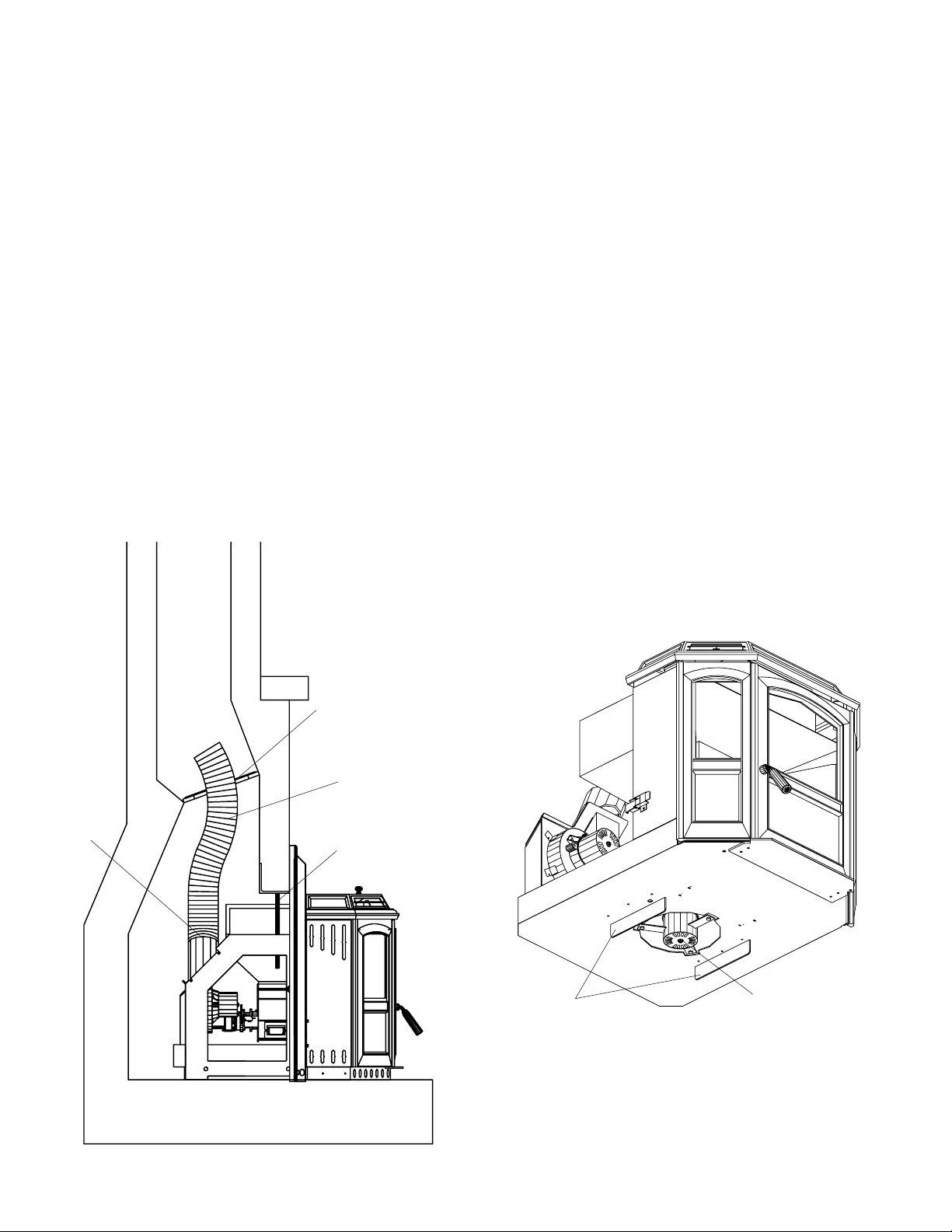
here
Metal damper
plate
Stainless steel
flex pipe
1/2" threaded rod
Guards
Be careful not to damage the distribution blower
located under the insert. There are guards on both
sides of the motor to allow the insert to rest on a flat
surface, however, extra care should still be taken.
Distribution Blower
3
Page 4

Mounting Shell
Wings
Brass Trim
After leveling, tighten the two 1/2"
threaded rods up against the
fireplace lintel.
Insert
Fig. 1
The Invincible Insert is made up of three main
parts. They are the mounting shell, the wings, and
the stove insert, fig. 1.
A unique feature of this unit is the fact that
the insert can be removed from the fireplace for
service without removing the mounting shell, the
wings or disconnecting the flue pipe.
Please note that the insert extends through the
rear of the mounting shell and this distance needs
to be considered when installing the shell. The
easiest place to see this is before you remove the
unit from the skid, fig.3.
Installing the Mounting Shell
Before installation, remove the damper and
any accessories from the fireplace. It is intended
that a four inch stainless steel flex pipe shall be
connected to the pipe on the rear of the mounting
shell and extend up through the damper opening.
The pipe shall be sealed at the damper opening
with a metal plate or packed with fiberglass.
Install brass trim on wings with hardware
provided. Bolt wings to shell with button head
bolts.
Place flex pipe up through damper opening
and seal around the pipe. The pipe should be able
to slide down over the flue on the shell, and sealed
with high temp silicone.
Place shell with wings attached into the
fireplace. Level the wings in all directions with
the leveling bolts in the base of the shell. After
leveling, tighten the two 1/2" threaded rods up
against the fireplace lintel, fig. 2. Do not overtighten.
Leveling bolt holes
Fig. 2
Fig. 3
Note extension
4
Page 5

Installing Insert
Slide two four foot long wood 2 x 4's into the
bottom of the shell as shown in fig. 4. Support the
ends of the 2 x 4's by cutting two pieces the proper
height for your hearth. A cross brace between the
two supports is recommended.
Place the insert on top of the 2 x 4's and slide
back until the bottom is started onto the shell.
Unpack the control board and install. This
can be done with the wiring attached by bringing
the control through the wing from the back. The
control can be mounted from the front if the wiring
harness is disconnected and reconnected after
mounting. Be sure to put the green wires on the
stud behind the wing. This stud also has the green
wire from the power cord on it, fig 5.
Next slide the insert to within an inch of
home position. Align the latches on the sides of
the insert and slide in the rest of the way . Always
be sure no wires are being pinched. Latch the two
latches and remove the 2 x 4's. Reattach the side
panels and bottom air intake grill, fig. 6.
Place the Room Sensing Probe in the desired
location and run standard thermostat wire back to
the terminals on the left wing and connect with the
two terminals provided, fig. 7. Connect the power
cord to a 120 volt receptacle.
Control Board
Install green wires on this stud.
Fig. 5
Latch
Standard 2 x 4
Fig. 4
Vertical Support
5
Page 6

Right Side Panel
Final Assembly
Install W ooden Door Handle
with 1/4 x 20 x 2 1/2 bolt.
Install Brass Hopper Knob with
10-32 x 1/2 bolt.
Install the two Firebricks on the
angle iron behind the burn pot as
shown in fig. 7.
Remove tape from Flame Guide
and make sure it is resting on the
burn pot as shown in fig. 7.
Put the ash pan back in the
stove.
Left Side Panel
Room Sensing
Probe
This very small probe can be
placed almost anywhere and go
unnoticed.
Fig. 6
Air Intake Grill
Brass Hopper
Knob
Firebricks
Plug into a 120 volt
receptacle
Flame Guide
Door Handle
Fig. 7
6
Page 7

Operation
Starting First Fire
Be sure the power cord is plugged into a 120 volt
receptacle. This can be verified by the red power
light on the control panel.
Fill the hopper with pellets, fig. 12.
Fig. 9
Fig. 8
Fig. 10
1"
Fill the burn pot with pellets to a level just short
of overflowing, fig. 8.
Adjust feed rate. If this is your first fire or you
are trying different pellets, set the feed adjuster
to "3", fig. 9. This is a conservative number and
will probably need to be increased. After you
know a feed rate setting that works well, use
that setting. Remember too high a feed rate will
waste fuel.
Turn Mode selector to "OFF" and then to
"Stove Temp". This will turn the combustion
blower to high. When starting a fire always turn
the mode selector to "OFF" before selecting the
desired mode. This resets the control for startup.
Turn Temp Dial to 7. This will allow the stove to
burn at maximum for feed rate adjusting purposes.
Apply starting gel to pellets in burn pot and light
the gel. Close the door after lighting.
At this point the distribution and combustion lights
will be on and the feed motor light will be off.
As the temperature of the fire increases, the feed
motor light will come on and pellets will feed
into the burn pot. As the stove temperature
increases the distribution blower speed will
increase.
Fig. 10A
After 30 to 45 minutes it may be necessary to
readjust the feed rate. The feed rate should be
adjusted so there is about one inch of ash in
front of the fire, fig. 10A.
7
Page 8

Scrape floor of burn pot with scraper to
remove any carbon build-up before
starting a new fire.
Fig. 11
When filling hopper be sure to
remove any pellets from ledge
before closing lid.
Starting a fire after pr oper
Feed Rate is known.
Clean burn pot with scraper (supplied).
Fill the hopper with pellets.
Fill the burn pot with pellets to a level just short
of overflowing.
Adjust feed rate to proper setting.
After you know what feed rate works well, then
use that setting. (For example a setting of "5"
produces 1" or more of ash on the burn pot with
the brand of pellets you are using.) Remember,
too high a feed rate will waste fuel.
Turn Mode selector to "OFF" and then to the
desired mode.
Turn Temp Dial to the desired temperature. In
Room Temp Mode this would be the outer scale
marked in degrees. In Stove Temp Mode this
would be the inner scale marked from 1 to 7.
Apply starting gel to pellets in burn pot as shown
on fig. 10 and light the gel. Close the door after
lighting.
At this point the distribution and combustion lights
will be on and the feed motor light will be off.
As the temperature of the fire increases, the feed
motor light will come on and pellets will feed
into the burn pot. As the stove temperature
increases the distribution blower speed will
increase.
Fig. 12
8
Page 9

Fig. 13
This setting will produce medium heat with the
distribution blower on "low".
This setting will produce a room temperature of 70
degrees with the distribution blower at medium speed.
When to use "Stove Temp
Mode"
In "Stove Temp Mode" the Stove Temp Dial
determines the temperature of the stove. Heat
output and fuel consumption will remain constant. This makes it possible to tell how long a
hopper full of pellets will last. The distribution
blower speed will vary according to the position
of the mode selector, fig. 13.
When to use "Room Temp
Mode"
In "Room Temp Mode" heat output is controlled automatically by the Room Sensing Probe.
When the Room Sensing Probe calls for heat, the
stove will increase output. When the Room Sensing Probe is getting close to the set temperature,
the stove will begin to level off output and keep the
fire burning at just the right temperature to maintain that setting.
High output is determined by the feed rate.
The maximum feed rate should be set for 1" of ash
in front of fire.
In "Room T emp Mode" fuel consumption is
sacrificed for exact room temperature. Therefore,
as it gets colder more pellets will be burned
automatically.
The distribution blower speed will vary
according to the position of the mode selector, fig.
13.
This setting will produce continuous maximum heat output
with the distribution blower at full speed.
Shut-Down Procedure
To kill the fire or stop burning the stove, Turn
the Mode Selector to "OFF". This will cause the
fire to diminish and burn out. When the fire burns
out and the stove cools down everything will stop.
If you pull the plug to shut down the stove, all
motors will stop. This may cause incomplete
combustion and smoke in the firebox. If the load
door is opened the smoke may escape.
The best way to shut down the stove is simply
let it run out of pellets, then the stove will shut
down automatically .
9
Page 10

Power Light
Indicates power to the
control.
Secondary
function: Blinks every
15 seconds when the
feed adjuster is in
"Test Mode". This
verifies feeder switch
operation.
Status Light
Blinks to Indicate
errors listed below.
Indicates Power to
distribution blower.
Indicates Power to
combustion blower.
ESP CONTROL
Feed adjuster
Sets the maximum feed
rate
Test
Runs all motors at
full speed for two
minutes to check
operation. After two
minutes the stove
will go to minimum
burn and the blowers
will alternate from
high to low every two
minutes to remind
you that you are still
in "Test Mode".
Distribution Blower
speed adjustment range.
Indicates Power to
the feed motor.
Temp dial
Allows you to adjust the Room temperature
in Room Temp Mode using the outer scale
marked in degrees Fahrenheit. It also
allows you to adjust the stove temperature
while in Stove Temp Mode using the inner
scale marked from 1 to 7.
Status light error messages:
1 Blink: Indicates control board self diagnostic
failure. This requires a manual reset*.
2 Blinks: Indicates that the feeder position switch
has not sensed the slide plate in the home position
for 30 minutes. This means that the slide plate may
be stuck do to a foreign object in the fuel or the
switch has failed. If the switch has failed the stove
will operate normally , however if turned to the
"OFF " position the stove will go to minimum burn
and will only shut down when it runs out of fuel. If
the slide plate frees its self the status light will
Mode Selector
Allows you to choose between Room
Temp Mode, Stove Temp Mode, or OFF.
Also allows you to vary the distribution
blower speed by turning the knob to the
high or low side of each mode.
automatically reset. If the error continues call your
Harman Dealer.
3 Blinks: Indicates ESP (Exhaust Sensing Probe)
failure. This requires a manual reset*.
4 Blinks: Can occur only in Room T emp Mode
and indicates Room Sensing Probe failed or not
installed. If a Room Sensing Probe is then installed
the status light will automatically reset.
* Manual reset, disconnect power cord for a few
seconds and reconnect. If error still occurs call
your Dealer.
10
 Loading...