

Page 1
Installation & Operating Manual
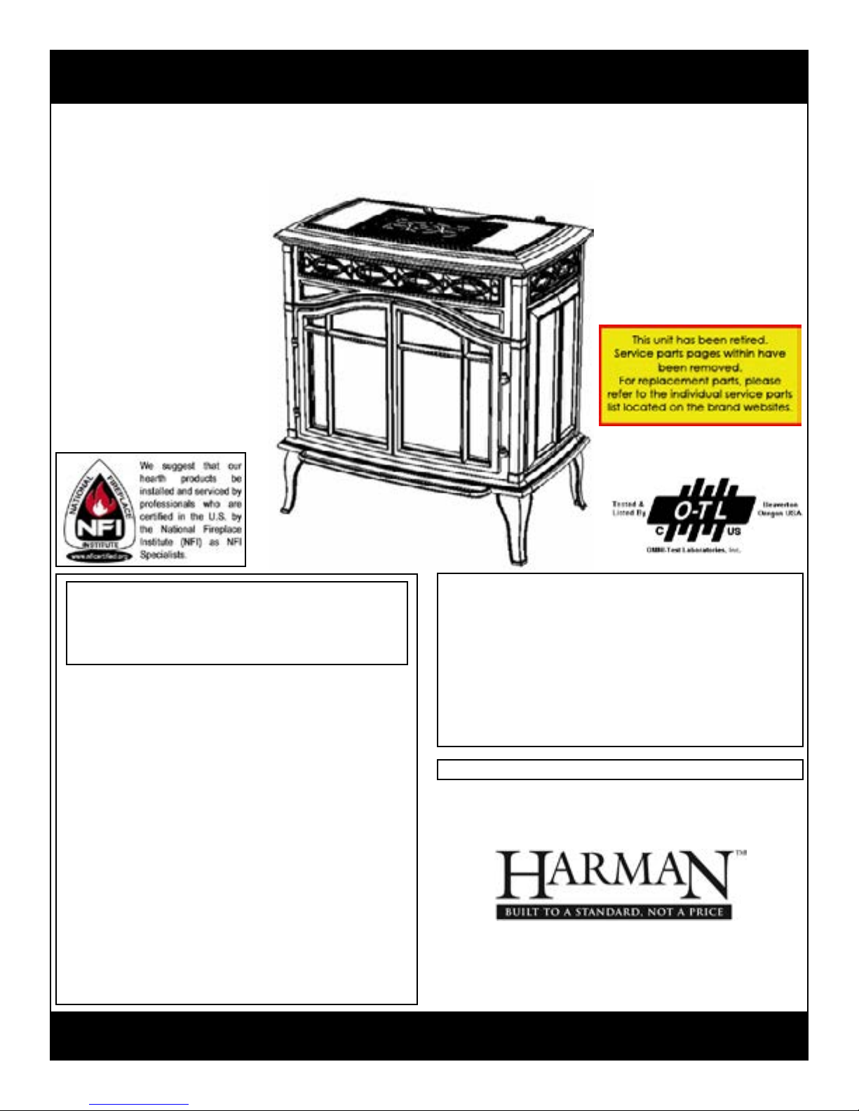
The Harman FireLuxe Direct Vent Gas Stove
With Top Cooking Burner System
WARNING: If the information in these
instructions is not followed exactly, a re or
explosion may result causing property
damage, personal injury or loss of life.
- Do not store or use gasoline or other
ammable vapors and liquids in the vicinity of
this or any other appliance.
- WHAT TO DO IF YOU SMELL GAS
• Do not try to light any appliance.
• Do not touch any electrical switch; do not
use any phone in your building.
• Immediately call your gas supplier from a
neighbor’s phone. Follow the gas supplier’s
instructions.
• If you cannot reach your gas supplier, call
the re department.
- Installation and service must be performed
by a qualied installer, service agency or
the gas supplier.
Report # 135-S-15-5
This appliance may be installed in
an aftermarket, permanently located
manufactured home (USA only) or in a mobile
home, where not prohibited by local codes.
This appliance is for use only with the type of
gas indicated on the rating plate. This appliance
is not convertible for use with other gases,
unless a certied conversion kit is used.
Ce manual est disponsible en Français sur demande.
R6
INSTALLER: Leave this manual with the appliance.
CONSUMER: Retain this manual for future reference.
Page 2
AVERTISSEMENT: Assurez-vous de bien suivre
les instructions données dans cette notice pour
réduire au minimum le risque d’incindie ou
d’explosion ou pour éviter tout dommage
matériel, toute blessure ou la mort.
- Ne pas entreposer ni utilizer d’essence ni
d’autres vapeurs ou liquides inammables dans
le voisinage de cet appareil ou de tout autre
appareil.
- QUE FAIRE SI VOUS SENTEZ UNE ODEUR DE
GAZ:
• Ne pas tenter d’allumer d’appareil.
• Ne touchez à aucan interrupteur. Ne pas
vous servir des téléphones se trouvant
dans le bâtiment où vous trouvez.
• Appelez immédiatement votre
fournisseur de gaz depuis un voisin.
Suivezles instructions du fournisseur.
• Si vous ne pouvez rejoindre le fournisseur
de gaz, appelez le service des incindie.
- L’installation et l’entretien doivent être assurés
par un installateur ou un service d’entretien
qualié ou par le fournisseur de gaz.
Cet appareil peut être installé dans une maison
préfabriquée (mobile) déjà installée à demeure
si kes règlements locaux le permettent.
Cet appareil doit être uniquement avec las type
de gaz indiqué sur la plaque signalétique. Cet
appareil ne peut être converti à d’autres gaz,
sauf si une trousse de conversion est utilisée.
Ne pas utiliser cet appareils’il a été plongé,
meme partiellement, dans l’eau. Appeler un
technician qualié pour inspecter l’appareail et
remplacer toute partie du système de commande
et toute commande qui a été plongée dans /’eau.
Attention. Au moment de l’entretien des
commandes, étiquetez tous les ls avant de les
débrancher. Des erreurs de la câblage peuvent
entraîner un fonctionnement inadequate et
dangereux.
S’assurer que l’appareil fonctionne adéquatement
une fois l’entretien terminé.
AVERTISSEMENT. Ne pas utiliser l’appareil
si le panneau frontal en verre n’est pas en place,
est craqué ou brisé. Conez le remplacement du
panneau à un technician agree.
INSTALLATEUR: Laissez cette notice avec l’appareil.
COMSOMMATEUR: Conservez cette notice pour consultation ultérieur.
Page 3

Table Of Contents
IMPORTANT SAFETY INFORMATION 4
SPECIFICATIONS 5
INSTALLATION 6
MASSACHUSETTS REQUIREMENTS 7
VENTING 8
ASSEMBLY 14
LIGHTING AND OPERATION 23
REMOTE CONTROL HANDSET OPERATION & PROGRAMMING 26
MAINTENANCE 28
WARRANTY 30
3
Page 4

Important Safety Information
The installation must conform with local codes or, in the absence of local codes, with the National Fuel
Gas Code, ANSI Z223.1 or the Canadian Installation Code, CAN/CGA B149.
A manufactured home (USA only) or mobile home OEM installation must conform with the Manufactured
Home Construction and Safety Standard, Title 24 CFR, Part 3280 or when such a standard is not applicable,
the Standard for Manufactured Home Installations, ANSI/BCSBCS A225.1, or Standard for Gas
Equipped Recreational Vehicles and Mobile Housing, CSA Z240.4.
The appliance and its appliance main gas valve must be disconnected from the gas supply piping system
during any pressure testing of that system at test pressures in excess of 1/2 psi (3.5 kPa).
The appliance must be isolated from the gas supply piping system by closing its equipment shutoff valve
during any pressure testing of the gas supply piping system at test pressures equal to or less than 1/2 psi
(3.5kPa).
The installation must provide for adequate ventilation air to the appliance.
This gas appliance must not be connected to a chimney ue serving a separate solid-fuel burning appliance.
The appliance, when installed, must be electrically grounded in accordance with local codes, or, in the
absence of local codes, with the National Electrical Code ANSI/NFPA 70, or the Canadian Electrical Code,
CSA C22. 1.
When the appliance is installed directly on carpeting or non-ceramic tile or other combustible material other
than wood ooring, the appliance shall be installed on a metal or wood panel extending the full width and
depth of the appliance. A commercially available hearth pad meets this requirement.
The appliance area must be kept clear and free from combustible materials, gasoline and other ammable
vapors and liquids.
The ow of combustion and ventilation air must not be obstructed.
Do not use this appliance if any part has been under water. Immediately call a qualifed service technician
to inspect the appliance and to replace any part of the control system and any gas control which has been
under water.
Due to high temperatures, the appliance should be located out of trafc and away from furniture and
draperies.
Children and adults should be alerted to the hazards of high surface temperatures and should stay away to
avoid burns or clothing ignition.
Young children should be carefully supervised when they are in the same room as the appliance.
Clothing or other ammable material should not be placed on or near the appliance.
Any screen or guard removed for servicing an appliance must be replaced prior to operating the appliance.
Installation and repair should be done by a qualied service person. The appliance should be inspected
before use and at least annually by a professional service person. More frequent cleaning may be required
due to excessive lint from carpeting, bedding material, etc. It is imperative that the control compartments,
burners and circulating air passageways of the appliance be kept clean.
WARNING: Do not operate the appliance with the glass front removed, cracked or broken.
Replacement of the glass should be done by a qualied service person.
WARNING: Use only replacement glass, part number 3-40-21001500 and glass gasket, part number
3-44-00539. Do not use substitute materials. Do not strike or slam the glass front. Do
not use abrasive cleaners. Do not clean when hot.
4
Page 5
Specications
MAIN BURNER Natural Gas Propane (LP)
Input Rating-Btu/hr 36000 36000
Min. Input-Btu/hr 23000 23000
Orice-DMS #34 #50
COOKING BURNER
Input Rating-Btu/hr 12000 12000
Min. Input-Btu/hr 3500 3500
Orice-DMS #52 #58
GAS SUPPLY
Manifold Pressure 4.5”w.c./1.1kPa 10.0”w.c./2.5kPa
Min. Supply Pressure 5.0”w.c./1.3kPa 11.0”w.c./2.8kPa
Max. Supply Pressure 10.0”w.c./2.5kPa 13.0”w.c./3.3kPa
Annual Fuel Utilization Efciency (AFUE) 72.7% 74.9%
Steady State Efciency 73.4% 75.6%
It is recommended that the pilot ame be turned off if the appliance will not be in use for an extended pe-
riod of time.
This appliance is equipped for use with the fuel type indicated on the rating plate. Fuel conversion kits that
include the necessary parts and instructions are available from your installer, dealer or Harman Stove Co.
This appliance has been certied by OMNI-Test Laboratories, Inc. to ANSI Z21.88-2005 • CSA 2.33-2005
Vented Gas Fireplace Heaters and CAN1-2.17-M91, Gas-Fired Appliances for Use At High Altitudes.
The FireLuxe is approved for installation at elevations up to 2000 feet in the U.S. and 1370 meters (4500
feet) in Canada without change. If your installation is at an elevation greater than these, consult with the
local authority having jurisdiction for gas product installations to determine their specic requirements for
high altitude installations.
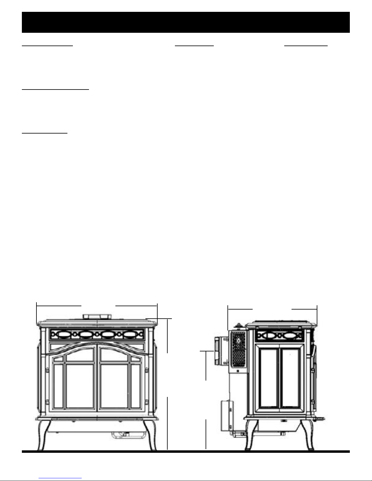
28” (71 cm)
20½” (52 cm)
30½” (77.5 cm)
23¼” (59 cm)
5
Page 6
Installation
Several issues must be addressed when selecting a suitable location for your FireLuxe. The minimum
clearances to combustible construction are listed below. In addition, access to the gas supply and electrical
supply must be considered. The location of the stove will also affect the venting requirements and you must
be certain the location will allow compliance with the venting requirements shown on pages 8 – 13. You
must also insure that your installation provides adequate accessibility clearance for servicing and proper
operation.
When the appliance is installed directly on carpeting or tile or other combustible material other than wood
ooring, the appliance shall be installed on a metal or wood panel extending the full width and depth of the
appliance.
Installation and repair should be done by a qualied service person. The appliance should be inspected
before use and at least annually by a professional service person. More frequent cleaning may be required
due to excessive lint from carpeting, bedding material, etc. It is imperative that the control compartments,
burners and circulating air passageways of the appliance be kept clean.
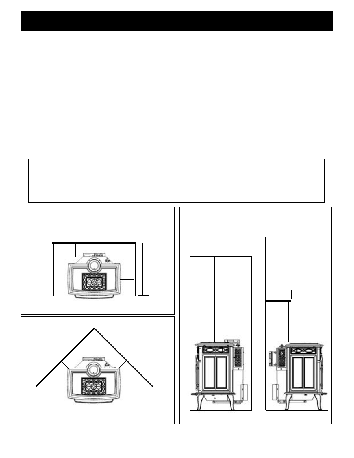
MINIMUM CLEARANCES TO COMBUSTIBLE CONSTRUCTION
Stove to Left Side Wall 6” (150mm) Stove to Corner Wall 6” (150mm)
Stove to Right Side Wall 6” (150mm) Stove to Ceiling 30” (760mm)
Stove to Rear Wall 6” (150mm) Stove to 10” Deep Mantel 30” (760mm)
Max. Alcove Depth 24” (610mm)
A = 6” (150 mm)
B = 6” (150 mm)
C = 6” (150 mm)
D = 24” (610 mm) Max. Alcove Depth
C
A
Sidewalls
E = 6” (150 mm)
E
F = 30” (760 mm)
G = 30” (760 mm)
H = 10” (250 mm) Max.
D
B
H
F
G
E
Corner
Ceiling
Mantel
6
Page 7

Installation
NOTE: If you will be installing the optional warming shelves, make sure to plan for the additional width
that they occupy. For the details, see the information included with the warming shelf kit.
The gas stove is shipped with a exible connector that has a 1/2” NPT female connection. The gas supply
piping should have a separate gas shutoff valve and a 1/8” NPT plugged tapping upstream of the valve.
The stove and its main control valve must be disconnected from the gas supply piping system during any
pressure testing of that system at test pressures in excess of 1/2 psi (3.5 kPa). The stove must be isolated
from the gas supply piping system by closing the main control valve during any pressure testing of the
gas supply system at test pressures equal to or less than 1/2 psi (3.5 kPa). After the gas supply has been
connected, apply a soapy water solution to all the ttings to check for gas leaks. Never use a ame to test
for leaks.
REQUIREMENTS FOR THE COMMONWEALTH OF MASSACHUSETTS
This product must be installed by a licensed plumber or gas tter when installed within the Commonwealth
of Massachusetts. If this appliance is installed in a dwelling, building or structure used in whole or in part
for residential purposes and the installation includes a horizontal vent termination that is less than seven
(7) feet above the nished grade in the area of the venting, including but not limited to decks and porches,
a hard-wired carbon monoxide detector with an alarm and battery back-up must be installed on the oor
level of the dwelling, building or structure where the appliance is to be installed.
Additionally, a hard-wired or battery operated carbon monoxide detector with an alarm must be installed
on each additional level of the dwelling, building or structure served by the appliance. It shall be the
responsibility of the property owner to secure the services of qualied licensed professionals for the
installation of hard-wired carbon monoxide detectors.
In the event that the horizontally vented appliance is installed in a crawl space or attic, the hardwired
carbon monoxide detector with alarm and battery back-up may be installed on the next adjacent
oor level.
In the event that this requirement cannot be met at the time of completion of the installation of the
appliance, the owner shall have a period of thirty (30) days to comply with the requirement. However,
during said thirty (30) day period, a battery operated carbon monoxide detector with alarm must be installed.
Each carbon monoxide detector as required in accordance with the above provisions must comply with
NFPA 720 and be ANSI/UL 2034 and IAS certied.
In addition, when the stove is horizontally vented and the vent termination is less than seven (7) feet
above nished grade a metal or plastic identication plate must be permanently mounted to the exterior of
the building at a minimum height of eight (8) feet above grade directly in line with the exhaust vent terminal.
The sign shall read, in print size no less than one-half (1/2) inch in size, “GAS VENT DIRECTLY BELOW.
KEEP CLEAR OF ALL OBSTRUCTIONS”.
A COPY OF THESE INSTRUCTIONS PLUS ALL VENTING INSTRUCTIONS WHICH INCLUDE
PARTS LISTS, AND/OR ALL VENTING DESIGN INSTRUCTIONS MUST REMAIN WITH THE STOVE AT
THE COMPLETION OF THE INSTALLATION.
ATTENTION INSTALLERS: Mark below which venting system was used in the installation. These
instructions must remain with the FireLuxe Installation & Operation Manual.
Simpson DuraVent GS AmeriVent Direct Security Secure Vent Selkirk DT Excel Direct
7
Page 8
Venting
The FireLuxe Gas Stove has been tested and listed for installation with 4” X 6 5/8” Simpson DuraVent GS,
AmeriVent Direct, Security Secure Vent, ICC Excel Direct and Selkirk DT direct venting components. The total
vent length may not exceed 40 feet, including vertical rise and horizontal run. The vent lengths are measured
from the stove, not the oor. The minimum vertical rise required is 2 feet. The maximum allowed horizontal
vent run is 20 feet when the venting includes at least 5 feet of vertical rise. The maximum allowed horizontal
vent run for vertical rises of less than 5 feet is shown in the venting charts. No more than three elbows may
be used in any installation. The venting charts include the use of one elbow. For the second or third elbows
that are included in the installation, add 4 feet to the actual horizontal run for each elbow to determine the
equivalent horizontal run for the installation.
The venting charts allow a simple way to determine the recommended initial settings for both the air inlet
and exhaust restrictors. These settings have been determined by extensive testing and will be a good starting
point while setting up the stove. Small adjustments from these settings may be needed to account for specic
installation variables. Please see the instructions on pages 21 - 22 for how to adjust the restrictors.
The letters (A-E) designate the position of the air inlet restrictor. When ½ is added to the letter designation, this
indicates that the position is halfway between adjacent letters. The numbers (0-8) indicate the position of the
exhaust restrictor. When ⅛, ¼, ⅜, ½, or ¾ is added to the number designation, this indicates that the position
is fractionally between adjacent numbers. For example, 5¼ is one-fourth the way between 5 and 6.
To use the charts, determine the horizontal run length and vertical rise length (in feet) for your installation.
If more than one elbow is used, add 4 feet to the actual horizontal run length for each additional elbow to
get the equivalent horizontal run for the chart. Note: Remember that a maximum of three elbows is allowed.
Select the venting chart for the fuel type (Natural Gas or Propane (LP) Gas) and nd the box on the chart that
corresponds to the vertical rise and actual horizontal run (or equivalent horizontal run, if two or three elbows
are used) and read the settings for the inlet air restrictor (A-E) and exhaust restrictor (0-8).
Examples are shown below and on page 9.
The FireLuxe is shipped with a Simpson DuraVent GS starter section that is specically designed for the
FireLuxe. Regardless of the venting brand you chose, you must use the provided DuraVent starter section.
All of the venting brands listed for use with the FireLuxe are compatible with the provided starter section. For
venting system installation details, refer to the instructions provided with the venting system you have chosen.
Each brand has specic installation requirements that must be followed to insure a safe and functional venting
system for your FireLuxe.
Note: The FireLuxe is shipped from the factory with restrictor settings for 2 feet of vertical rise and 1 foot
of horizontal run and for the fuel type listed on the rating plate attached to the rear of the stove.
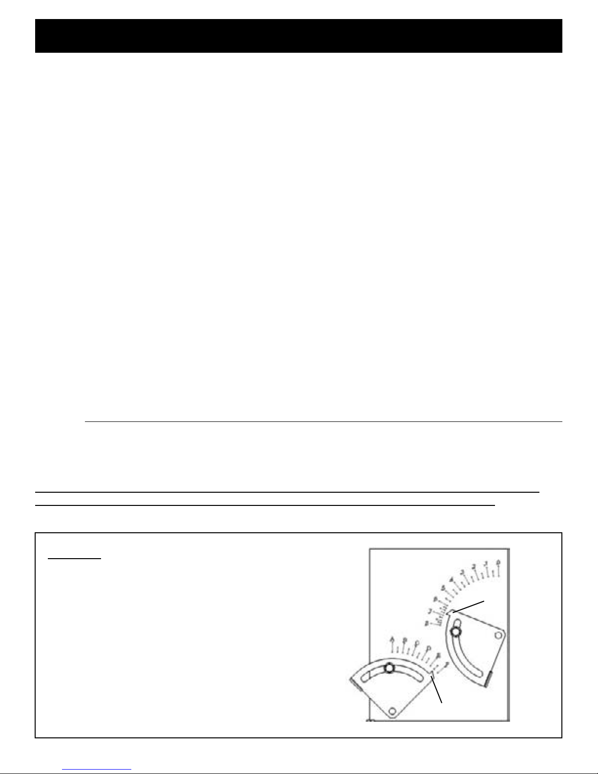
Example 1
Fuel = Propane (LP)
Vertical Rise = 15 feet
Exhaust
Horizontal Run = 8 feet
Elbows = 1 (one)
Equivalent Horizontal Run = 8 feet
6¾
Air Restrictor Setting = E½
Exhaust Restrictor Setting = 6¾
E½
Inlet Air
8
Page 9
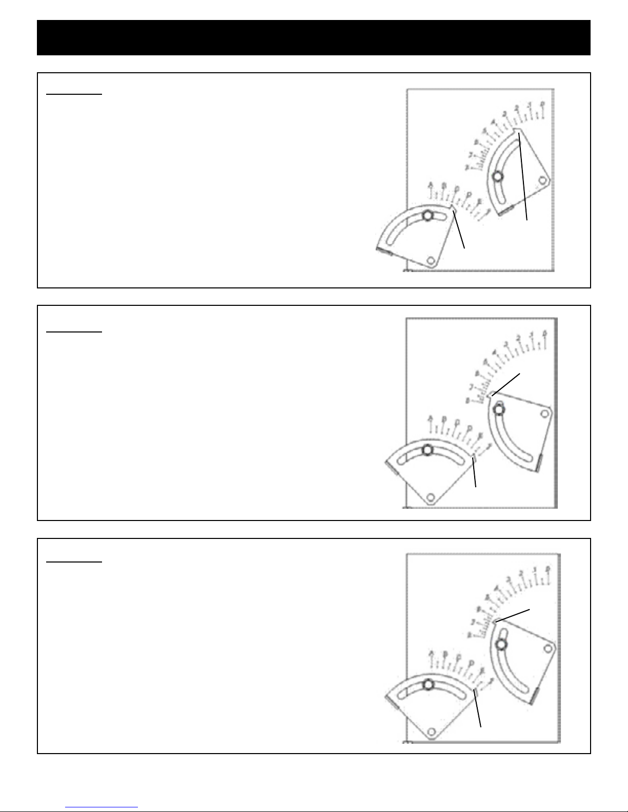
Example 2
Fuel = Propane (LP)
Vertical Rise = 6 feet
Horizontal Run = 8 feet
Elbows = 3 (three)
Equivalent Horizontal Run = 16 feet (8+4+4)
Air Restrictor Setting = C
Exhaust Restrictor Setting = 3
Example 3
Venting
3
Exhaust
C
Inlet Air
Fuel = Natural Gas
Vertical Rise = 22 feet
Horizontal Run = 0 feet
Elbows = 0 (none)
Equivalent Horizontal Run = 0 feet
Air Restrictor Setting = E½
Exhaust Restrictor Setting = 7⅜
Example 4
Fuel = Propane (LP)
Vertical Rise = 12 feet
Horizontal Run = 4 feet
Elbows = 1 (one)
Equivalent Horizontal Run = 4 feet
Exhaust
7⅜
E½
Inlet Air
Exhaust
Air Restrictor Setting = E½
Exhaust Restrictor Setting = 6½
6½
E½
Inlet Air
9
Page 10
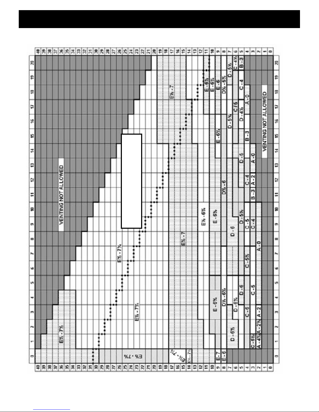
Venting
Natural Gas Venting
IF YOUR VENTING CONFIGURATION
FALLS ABOVE THIS DOTTED LINE,
SEE PAGE 12
Horizontal Run - In Feet
Vertical Rise - In Feet
10
Page 11

Venting
Propane (LP) Gas Venting
IF YOUR VENTING CONFIGURATION
FALLS ABOVE THIS DOTTED LINE,
SEE PAGE 12
Vertical Rise - In Feet
11
Horizontal Run - In Feet
Page 12

Venting
PLEASE NOTE: If your specic venting conguration falls in a box in the venting charts (on pages 10 &
11) that is above the dotted line (••••), you must use one of the approved direct vent venting systems
that utilizes a stainless steel inner liner. The dotted line corresponds to a total vent length of 30 feet including
vertical rise and horizontal run. This requirement is part of the ANSI standards and is based on testing
conducted to determine where the exhaust gas temperature drops to the point where condensation might
occur in the vent pipe. The standards require the use of corrosion resistant liner materials if that specic
total vent length is exceeded.
VENTING INTO AN EXISTING MASONRY OR CLASS A CHIMNEY
The FireLuxe has been tested and found to be in compliance when using an existing chimney as the air
conduit for the direct venting system. However, before proceeding, check with the local authority
having jurisdiction to see if this type of installation is allowed in your area.
This type of installation is used when replacing an existing wood-burning stove with a FireLuxe direct vent
gas stove. Check with the installer or venting manufacturer to see if they have the needed components
or kits for this type of installation. Also, check the vent manufacturer’s installation instructions for the
specic details and requirements for this type of installation. The chimney must be in good condition with
no cracks or leaks for this type of installation (including the cleanout door) and the venting components
must be completely sealed where they meet the existing chimney. The chimney must not be connected to
any other appliances. Note: If your chimney has been problematic when using your woodstove (low draft,
backdrafts, etc.) performance problems may also occur when the chimney is used with a gas appliance.
VENTING INTO AN EXISTING FIREPLACE
The FireLuxe may be vented through an existing replace chimney. The replace opening must be at least
28” high. All clearances to adjacent combustible materials, including the mantel, must be in conformance
with the clearances shown on Page 6 of this manual. A special adapter and components are required to
convert the co-axial rear vent starter to a co-linear conguration that will allow separate 3” diameter exible
metal ducts (one for the air and one for the exhaust) to pass through the damper opening in the replace
and to run to the top of the chimney. A second special adapter is required at the top of the chimney to rejoin
the exible ducts back to a co-axial conguration and allow the use of standard vertical vent caps.
This chimney top adapter must be sealed to the top of the chimney to prevent air leakage. Check with the
installer or venting manufacturer to see if they have the needed components or kits for this type of installation.
Also, check the vent manufacturer’s installation instructions for the specic details and requirements for
this type of installation Note: Some gas stove manufacturers allow the air duct to terminate a few feet
above the replace damper. This is not allowed for the FireLuxe. Both the air duct and the exhaust duct
must run the full length from the stove adapter to the chimney top adapter.
When venting through a replace, the air and exhaust restrictors should be set using the charts below. The
minimum vent rise allowed is 10
feet. The maximum vent rise is
35 feet. Use the settings on the
charts that are the closest to your
actual vent rise. For example, if
your vent rise is 17 feet, use the
settings for 15 feet. If the vent
rise is 18 feet, use the settings for
20 feet. Note: The vent rises are
measured from the centerline of
the rear vent starter.
NATURAL GAS PROPANE (LP) GAS
Vert. Rise Restrictor Settings
feet Air Exhaust
10 C 4 1/2
15 D-1/2 6
20 D-1/2 6 1/2
25 D-1/2 6 1/2
30 D 6
35 C 4 1/2
Vert. Rise Restrictor Settings
feet Air Exhaust
10 A 0
15 D 5 1/2
20 D 6 1/4
25 D 6 1/4
30 C 1/2 5 1/2
35 C 4 1/2
12
Page 13

= Vent Terminal
V
Venting
Vent Termination Clearances
Venting terminals shall not be recessed into a wall or siding.
13
Page 14

Assembly
UNPACKING AND PLACING THE FIRELUXE
By now, you will have removed the shipping carton from the base pallet. The FireLuxe is shipped on
specially designed shipping supports that keep the weight of the stove off the legs to avoid damaging them
during transit. Cut the strapping that secures the stove to the pallet. The stove must be lifted straight up to
disengage it from the shipping brackets. The best place to lift is at the base of the stove sides. The stove
top and front have to be removed in order to unpack and install the logs and top cooking burner parts.
Removing them now will reduce the weight and make it easier to lift the stove. Also, locate the ashlip and
ashlip mounting hardware and set aside in a safe location. It will be installed later.
First, remove the cast iron stove top. This is accomplished by simply lifting up on the top as it is a gravity
t. The top is heavy and extra care should be taken when handling it, especially if the stove is enameled.
Set the top aside on a padded surface. A carpeted oor is a good choice.
Remove the top cooking grill and the cooking burner cover plate and set aside for now. They are packed in
bubble wrap or foam packing and are located on the now exposed top of the stove’s rebox.
Remove the stove front by lifting it straight up to disengage the tabs that secure it to the sides. Once it is
disengaged, you can move the front away from the stove body. Note: The front doors may have a tendency
to swing open while you are handling the front. Placing a small piece of masking tape around the two doors
where they meet at the center will keep the doors from moving. Set the front aside with the back side down
taking extra care if it is enameled.
With these parts removed and set aside, lift the stove up and off the pallet and set it near to its installation
position. Like any cast iron stove, it is best to pick the stove up while adjusting its position rather than
dragging it on its legs. This reduces the chances of damaging a leg or chipping enamel or of damaging the
hearth surface. This is the best time to install the optional blower kit if being used. See the instructions
included with the blower kit.
The legs have leveling screws that will allow you to compensate for irregularities on the surface under the
stove. Using as little adjustment as possible for each leveling screw, adjust them as needed to get the stove
as level as possible both side to side and front to back. This is important since the FireLuxe includes a top
cooking burner and having the stove level will reduce the likelihood of spillage while cooking.
The FireLuxe is shipped set up for the fuel type indicated on the rating plate attached to the rear of the
stove. Note: If you need to switch fuels, please see the instructions included with the appropriate fuel
conversion kit. The logs are shipped in protective material inside the rebox and do need to be unpacked
and
installed on the burner.
With the stove top and front removed and safely set aside
during the unpacking process, unlatch each of the three
glass frame latches by pulling forward on the latch nger
tabs while lifting up. See the adjacent illustration. This
will allow the glass frame to tip slightly forward. The glass
is loose in the frame, held in place only by friction from
the gasket so it is very important to support both the glass
and the frame when handling. Place your thumbs on the
outside of the glass frame and wrap your ngers around
the frame and onto the glass. Squeeze the frame and glass
while moving. Carefully lift the glass frame and glass up
and off the stove. Set the glass and frame aside on a padded
surface. The outside of the frame should be facing
down so the glass will stay in place.
14
Page 15

Assembly
LOGS AND EMBERS
Slide the logs and packing out of the rebox and set on the oor. Carefully unpack each of the four logs
and three loose ember pieces. The logs and embers are somewhat fragile and will not survive being
dropped from any signicant height. Remove the protective cover material from the top of the burner.
Each of the four logs is unique and must be placed in a precise location on top of the burner. The burner
and log system is designed to facilitate correct placement of the logs. Flat recessed areas on the burner top
are keyed to each of the four main logs. The rear logs also have locating pins with corresponding sockets
in the logs. The following illustration highlights these features.
Place the left rear log rst. There is a recessed area in the burner top as well as a locating pin and a
corresponding socket in the log. Line-up the socket over the pin and place the log in the recess.
Place the right rear log next. There is a recessed area on the top of the burner that corresponds to the
shape of the base of the log. Simply place the log in the recess. The following illustration shows the proper
positions for the two rear logs.
15
Page 16

Assembly
Place the left front log next. Again, there is a recess on the burner top that corresponds to the shape of the
at base of the log. Place the left end of the log in the recess and rest the right end on the left rear log using
the illustration below as a guide. Place the right front log last. Again, place the at base of the log in the
corresponding recess in the burner top per the illustration below.
There are three loose ember pieces. Each ember piece has a specic location on the burner. Refer to the
illustration below to get the proper placement and orientation for each ember piece. If you look carefully,
you will see that each ember has features that will help you in placement relative to the burner surface and
the logs.
16
Page 17

Assembly
When correctly placed, the logs and embers will look like the illustration below.
After the logs and embers have been placed, the next
step is to replace the glass panel and frame. Carefully
pick up the glass and glass frame assembly by grasping
the sides of the frame and using your thumbs and
ngers to hold the glass in place within the gasket and
frame.
With the glass frame (and glass) at a slight angle
(leaving room for your ngers between the frame and
the rebox) insert the bottom edge of the frame into
the frame retainer located on the bottom front of the
rebox. Take care to center the frame from left to
right. Once the bottom edge is in place, move your
ngers out of the way and press the top of the frame
against the rebox while pushing down to be sure the
frame is fully engaged in the frame retainer. Hold the
frame in place with one hand and engage the three
glass frame latches by pulling out and down while
hooking them over the frame.
Top or Rear Vent
The FireLuxe has provisions for either top or rear venting but is shipped from the factory set-up for top
venting. The rear position is sealed with a special cover plate. If your installation requires rear-venting,
you will need to reverse the positions of the starter section and the cover plate.
Remove the four screws that secure the vent starter section ange to the stove and remove the starter.
There are two ceramic ber gaskets that seal the starter to the stove. These gaskets are very important!
Take care in handling these gaskets as they are somewhat fragile and will tear. Remove the vent cover plate
from the rear of the stove following the same procedure as the starter. Install the cover plate on the top vent
opening.
17
Page 18

Assembly
Be sure that the inner and outer gaskets are in
their proper positions. Install and tighten the
four screws. Finally, install the vent starter
section in the rear vent position. Again,
make sure that the inner and outer gaskets are
in their proper positions and install and
tighten the four screws.
At this time, you will also want to install the
optional cast iron plate that lls in the top vent
cutout on the stove top. With the bottom of
the top facing up, place the ller plate in the
cutout with the ller plate edge molding
aligned with the edge molding on the top. Using
the bracket and three fasteners included
with the ller plate kit, secure the ller plate
to the top. See the illustration included with
the optional ller plate kit for more information.
It is now time to install the ashlip on the stove front and to install the stove front and stove top.
The ashlip is secured to the front using two brackets and four 1/4 – 20 hex head bolts. With the front facing
down on a padded surface, align the mounting bosses on the ashlip with the mounting bosses on the front.
Install the two “L”-shaped brackets with the slotted end on the ashlip. Tighten the bolts to the front but leave
the bolts to the ashlip nger tight. Carefully turn the front over. Adjust the ashlip so that it is tight
against the lower
molding on the front.
Tighten the ashlip
bolts. Take care with
an enamel stove to
prevent chipping.
Replace the stove
front by aligning the
outer edges with the
stove sides while the front is about ½ to 1” above its nal position. This is to allow the sheet metal tabs that
secure it to the sides to be above the mating cast iron tabs on the sides. Carefully push the front in while
allowing it to slide down. All four tabs (two top and two bottom) should engage with the sides. Once the front
has reached the proper position, check the vertical alignment by looking at the alignment of the edges of
the front to the casting details on the side. They should be parallel. If they are not, simply push or pull on the
front until a good visual alignment is obtained. Take extra care with this procedure if your stove is enameled.
Just move in small increments as you line up the tabs and lower the front into place. If you take your time,
you will avoid chipping. Remove any
masking tape used to secure the doors.
Next, install the brass diffuser ring and top burner
cover on the cooking burner. This is a small round
disk that sits on top of the brass diffuser ring on the
top burner. If you look at the back side of the diffuser,
you will see alignment tabs. They correspond to
alignment locations on the burner. The cover is simply
centered in the diffuser.
18
Page 19

Assembly
Next, reinstall the top. This is a gravity t. Carefully align the inner edge of the top with the outer edges of
the sides and front. Lower the top down into place. Check to see if it is level and push down as needed to
get the proper alignment relative to the aesthetic details on the front and sides.
Finally, install the top cooking grate. This simply sits over the burner. A raised border on the stove top
denes the cooking grate position.
BATTERY INSTALLATION OR REPLACEMENT
The batteries used to power the burner control systems on the FireLuxe should last a full season or more
with normal use. Battery life for the main burner control system will be reduced if you are manually modulating
the ame up and down on a frequent basis.
There are three battery locations.
The electronic ignition module for the cooking burner is located behind an access panel located on the
right rear of the stove (when looking from the stove front). A single fastener secures the panel. Simply
remove fastener and the panel to access the single 9-volt battery. Unsnap the old battery from the module
and replace with a fresh one. Use a high quality long-life alkaline battery. Replace the access panel and
fastener. Refer to the illustrations below.
The remote control handset is powered by a 9-volt battery.
There is a low battery indicator on the handset display panel.
To replace the battery, remove the access cover from the
rear of
the handset and unsnap the old battery. Replace with a high
quality long-life alkaline battery and reinstall the cover.
19
Page 20

Assembly
The main heating valve battery pack is located at the center rear of the stove. A removable valve access
panel covers the valve components and simply lifts up and off the stove back. The batteries are located in
the control module next to the actual valve. The battery access cover lifts and slides off to expose the four
AA batteries. Note the orientation of each battery as you replace the old with new as this is critical to the
operation of the control. Use only high quality long-life alkaline batteries. Replace the battery cover and
the valve access panel. Refer to illustrations below.
NOTE: The control module is secured to the valve bracket with hook-and-eye strips and can be pulled
away from the bracket if necessary to gain better access to the battery cover and compartment. Be certain
not to dislodge the wiring from the control module and be sure to place the module back it its original position
after the batteries and cover are installed.
GAS CONNECTION
The FireLuxe is shipped from the factory with a exible gas connector that has a 1/2” NPT female connection.
The gas supply piping should have a separate gas shut-off valve and a 1/8” NPT plugged tapping upstream
of the valve. The FireLuxe and its inlet regulator. Main burner valve and cooking burner valve must
be disconnected from the gas supply piping system during any pressure testing of that system at test
pressures in excess of 1/2 psi (3.5kPa). The FireLuxe must be isolated from the gas supply piping system by
closing the main control valve during any pressure testing of the gas supply system at test pressures equal
to or less than 1/2 psi (3.5kPa). After the gas supply has been connected, apply a soapy water solution to
all the ttings to check for gas leaks. Never use a ame to test for leaks.
20
Page 21

Assembly
PRIMARY AIR ADJUSTER
Your FireLuxe gas stove was shipped from the factory
equipped for the fuel type indicated on the rating
plate that is attached to the rear of the stove and the
primary burner air adjuster was set at the factory at the
recommended position for that fuel. If you will be using
the alternate fuel please see the instructions included
with the optional fuel conversion kit. This includes
instructions for the proper setting for the primary air
adjuster.
The recommended setting for propane is the fully-open
position. This corresponds to the adjuster screw fully
backed out. The recommended setting for natural gas
is the fully-closed position. This corresponds to the
adjuster screw fully screwed in.
Making small adjustments to the primary air setting will
let you adjust the way the ames look for your particular
installation. See the reference to primary air adjustment
in the section below that discusses the air inlet and
exhaust outlet restrictors.
AIR INLET AND EXHAUST OUTLET RESTRICTORS
The FireLuxe is equipped with externally adjustable restrictors for both the inlet air and the exhaust outlet.
This makes it possible to ne tune the direct vent system for the specic conditions of your installation.
The recommended settings are keyed to the specic details of your venting conguration.
To access the restrictor adjustment guide plates, you must rst remove the access plate. Looking at the
stove from the front, this plate is located on the upper left rear of the stove. If you have the optional blower,
the access plate also contains the blower speed control. Remove the single fastener that secures the
access plate. Set the plate aside (or if the blower is installed, let the plate hang on the wiring). Next remove
the heat shield. This is held in place with a single fastener located at the lower front corner of the shield. With
the fastener removed, tilt the heat shield as needed and remove. Refer to the illustrations below.
21
Page 22

Assembly
You will now see the two guide plates. The guide plates have a
pointer that corresponds to a letter scale for the air adjustment and
number scale for the exhaust adjustment. These are the letters and
numbers that are referenced in the venting charts on pages 10 and
11 and shown in detail in the examples shown on pages 8 and 9. To
change the setting, loosen the guide plate locking screws. Next
rotate each guide plate to the recommended setting for your
installation shown in the appropriate venting chart for natural gas
or for propane (LP) gas. Once the settings are correct, tighten the
locking
screws.
It is a good idea to test re the stove before you replace the heat
shield and access cover. Follow the lighting and operation
instructions starting on page 23. Allow the stove to burn for at least
20-30 minutes at high re while observing the ame. Although the
ames will become more luminescent as the stove heats up, the
tips of the ames should not be dark or sooty or extending so high
as to touch the bafe. If they are, some additional adjustment is
needed. First, check the position of the primary burner air adjuster.
For propane, the primary air adjuster should be in the fully-open
position. If it is not, loosen the adjuster screw locknut back out the adjuster screw. If no difference in the
ame appearance is noted, a small adjustment of the exhaust restrictor should be tried next. This can be
done with the stove operating but care must be taken not to touch hot surfaces while making the adjustment.
Loosen the exhaust guide plate locking screw and move the setting down by ¼ increment. For example,
move from a setting of 6 ½ to a setting of 6 ¼ . Tighten the locking screw and observe the ames. Repeat the
process until ame tips shorten and become lighter in color. No more than one full increment of adjustment
should be used. If no change in the ame appearance is noted after that, consult with a Harman Stove
Company representative.
If, after 20-30 minutes at high re, the ames are short or blue, the re is probably getting too much air.
You should rst reduce the primary burner air by loosening the adjuster screw locknut and turning the
adjuster screw in one turn. See the illustration on page 21 for the location of the primary air adjuster screw.
Wait a few minutes and observe the ames again. Make another one turn adjustment. If the ame appearance
has not changed after two turns of the adjuster screw, it is likely that there is another cause for the
short or blue ames. Note: Do not turn the primary air adjustment screw in more than two turns. The
ames should not have dark or sooty tips and should not be extending so high as to touch the bafe. If
adjusting the primary burner air doesn’t improve the ame appearance, a small adjustment of the inlet air
restrictor can be made. This can be done with the stove operating but care must be taken not to touch hot
surfaces while making the adjustment. Loosen the inlet air restrictor guide plate locking screw and move the
setting up by ¼ increment. For example, move from a setting of E to a setting of E ¼. Tighten the locking
screw and observe the ames. Repeat the process until ame tips begin to extend and become more yellow
in color. Note: DO NOT OVER-ADJUST THE INLET AIR RESTRICTOR. The ames should not have dark
or sooty tips and should not be extending so high as to touch the bafe.
Once all adjustments are made, make sure the inlet air and exhaust restrictor guide plate locking screws are
tight and replace the heat shield, heat shield fastener and the access plate and fastener. If an adjustment
was made to the primary burner air, tighten the locknut on the adjustment screw to lock in the new setting.
22
Page 23

Lighting & Operation
FOR YOUR SAFETY - READ BEFORE LIGHTING
WARNING: If you do not follow these instructions exactly, a re or explosion may
result causing property damage, personal injury or loss of life.
THIS APPLIANCE HAS TWO SEPARATE BURNER AND GAS CONTROL SYSTEMS. ONE SYSTEM
IS FOR THE MAIN HEATING BURNER AND THE SECOND IS FOR THE TOP COOKING BURNER.
A. BEFORE OPERATING EITHER BURNER SYSTEM, smell around the appliance area for gas. Be
sure to smell next to the oor because some gas is heavier than air and will settle on the oor.
WHAT TO DO IF YOU SMELL GAS
• Do not try to light the appliance.
• Do not touch any electric switch; do not use any telephone in your building.
• Immediately call your gas supplier from a neighbor’s telephone. Follow the gas supplier’s instructions.
• If you cannot reach your gas supplier, call the re department.
B. Use only your hand to operate the gas controls. Never use tools. If a knob will not push in or turn by
hand, don’t try to repair it, call a qualied service technician. Force or attempted repair may result in a
re or explosion.
C. Do not use this appliance if any part has been under water. Immediately call a qualied service technician
to inspect the appliance and to replace any part of the control system which has been under water.
LIGHTING INSTRUCTIONS - Main Burner
AUTOMATIC IGNITION
1. STOP! Read the safety information above.
2. This appliance is equipped with an igntion device that automatically lights the pilot. When using the
remote handset, do not try to manually light the pilot.
3. Push the OFF button on the remote handset to insure the appliance is off.
4. Wait ve (5) minutes to clear out any gas. Then, smell for gas, including near the oor. If you smell gas,
STOP! Follow A. in the safety information above. If you do not smell gas, proceed to step 5.
5. Turn the MAN knob to the ON, full counterclockwise position. Refer to Fig.1 on page 24.
6. Simultaneously press and hold the (star) and ▲(up arrow) on the remote control unit (see Fig.2)
until a short acoustic signal conrms the start sequence has begun; release the buttons. Continuing signals conrm the ignition sequence is in progress. Once pilot ignition is conrmed, there is gas ow to the
burner.
WARNING: When pilot ignition is conrmed, the valve motor turns automatically to maximum Flame
height.
Note: If the pilot does not stay lit after several tries, turn the main valve knob to OFF, full clockwise
position. Proceed to step 8.
7. Set the thermostat to the desired setting or use the remote control to adjust ame. In standby mode:
press ▲(up arrow) to increase the ame height, press ▼(down arrow) to decrease ame height or to set
appliance at pilot ame. See page 26 for remote handset programming instructions.
8. If the appliance will not operate, follow instructions “TO TURN OFF GAS TO MAIN BURNER” on the
next page and call your service technician or gas supplier.
23
Page 24

Lighting & Operation
MANUAL IGNITION
1. STOP! Read the safety information on the top of page 23.
2. Locate the valve on the back of the stove. Turn the main valve knob to the OFF, full clockwise
position.
3. Wait ve (5) minutes to clear out any gas. Then smell for gas including near the oor. If you smell
gas, STOP! Follow A in the safety information on page 23. If you don’t smell gas, proceed to Step 4.
4. Visually locate the pilot at the center rear of the rebox. Refer to Fig. 3 below.
5. With the MAN-knob in MAN position, a manual pilot valve operator is accessible (Refer to Fig. 1).
• Fully push down the manual pilot valve operator using a small screwdriver or pen tip and hold in
to start pilot gas ow. Immediately light the pilot by rapidly depressing the piezo igniter button
on the valve (See Fig. 1). Once the pilot ame is observed, continue to hold in the manual pilot
valve operator for about one (1) minute. Release the manual pilot valve operator. If the pilot
does not stay lit, repeat steps 2 through 5.
• Note: If the pilot does not stay lit after several tries, turn the main valve knob to OFF and proceed
to step 7.
6. Turn the MAN-knob to the ON, full counterclockwise position.
7. If the appliance will not operate, follow the instructions “TO TURN OFF GAS TO MAIN BURNER”
and call your service technician or gas supplier.
TO TURN OFF GAS TO MAIN BURNER
1. Press the OFF button on the remote (if available).
2. Turn the main valve knob to the OFF full clockwise position.
LIGHTING INSTRUCTIONS - COOKING BURNER
1. Stop! Read the safety information shown on the top of page 23.
2. Locate the cooking burner gas control knob at the top right rear of the appliance. Refer to Fig. 4 below
for more information.
3. With the valve in the OFF position, push down on the knob and turn counterclockwise to the H
(High) position. The cooking burner has a built-in electronic ignition system and the burner will ignite
automatically. If the burner does not light within ve (5) seconds, turn the knob to the OFF, full clockwise
position and call your service technician or gas supplier.
4. Adjust the burner for the desired cooking heat level.
TO TURN OFF GAS TO COOKING BURNER
1. To turn the cooking burner off, turn the knob to the OFF, full clockwise position.
24
Page 25

Lighting & Operation
COOKING BURNER OPERATION
The cooking burner on your FireLuxe functions like a cooking burner on any conventional kitchen range.
A battery-powered ame-sensing automatic ignition system lights the burner when you depress the control
knob and rotate counterclockwise to the High (H) position. You will hear a clicking sound and can observe
the spark arcing from the igniter electrode to the burner body. Once the burner is lit, the ame sensor will
shut off the spark. If, for any reason, the sensor does not detect a ame, the igniter will automatically resume
sparking until the ame is detected again. (will occur when open burning, with no cook pot or pan.)
The ames should be blue and evenly distributed around the perimeter of the burner. See the illustration
below.
Adjust the ame for the desired heat level by rotating the knob. To turn the burner off, rotate the knob
clockwise to the OFF position. (See g. 4 on page 24.)
Refer to the lighting instructions on page 24 and the lighting and operating instructions on the permanent
metal label attached by cable to the rear of the stove.
WARNING: THE COOKING BURNER IS FOR ATTENDED USE ONLY. DO NOT LEAVE “ON”
UNATTENDED FOR ANY REASON.
WARNING: CHILDREN AND ADULTS SHOULD BE ALERTED TO THE HAZARDS OF HIGH SURFACE
TEMPERATURES AND SHOULD STAY AWAY TO AVOID BURNS OR CLOTHING IGNITION. YOUNG
CHILDREN SHOULD BE CAREFULLY SUPERVISED WHEN THEY ARE IN THE SAME ROOM AS
THE APPLIANCE. CLOTHING OR OTHER FLAMMABLE MATERIAL SHOULD NOT BE PLACED ON
OR NEAR THE APPLIANCE.
WARNING: BASED ON SAFETY CONSIDERATIONS, THE COOKING BURNER FLAME SHOULD BE
ADJUSTED SO IT DOES NOT EXTEND BEYOND THE EDGE OF THE COOKING UTENSIL.
WARNING: BASED ON SAFETY CONSIDERATIONS, DO NOT USE THE COOKING BURNER FOR
SPACE HEATING UNDER ANY CIRCUMSTANCES.
PILOT AND MAIN BURNER OPERATION
Follow the lighting instructions on pages 23 – 24. When the pilot is lit and operating properly, it should
look like the illustration above. One ame will be directed at the pilot thermocouple and the other will be
emanating toward the burner. If the pilot ames do not resemble the illustration above, see the instructions
on page 26 for pilot ame adjustment.
After the main burner ignites and has been in operation for a few minutes, the ames should look like the
illustration on the top of page 26. Flame height will vary depending on the ring rate but ames should be
burning in all of the indicated areas.
25
Page 26

Lighting & Operation
Main Valve Knob
Pilot Gas
adjustment
screw. (turn with
screwdriver)
MAN- knob
REMOTE CONTROL HANDSET
OPERATION AND PROGRAMMING
Setting °C/24 hour or °F/12 hour clock
(Display and timer / Thermostat handsets)
1. Press OFF and ▼ (down arrow) until display
changes from farenheit / 12 hour clock to
Celsius / 24 hour clock and vice-versa.
Setting the Time
(Display and Timer / Thermostat handsets)
1. The display will ash after either:
a. Installing the battery or
b. Simultaneously pressing the ▲ (up arrow)
and ▼ (down arrow).
2. Press ▲ (up arrow) to set the hour, and the ▼
(down arrow) to set the minutes.
3. Press OFF to return to manual mode or simply
wait and it will automatically return to manual
mode.
PILOT FLAME ADJUSTMENT
The pilot ow is factory set to maximum. The pilot
ame should envelope 3/8” to 1/2” of the
thermocouple. See the illustration above.
The adjustment screw can be reached through the
MAN-knob. See top illustration above.
1. Turn the Man-knob to the ON position.
2. It is now possible to pierce through a lm on the
cover with a screwdriver to reach the adjustment
screw beneath.
3. Turn the adjustment screw clockwise to decrease
or counterclockwise to increase the pilot ame.
Automatic Pilot Mode With Thermostat Remote
If there is no transmission from the handset to the
receiver within a 6 hour period, the appliance will go
to standby (pilot) mode.
Flame Height Adjustment
In “MAN” mode: Press ▲ (up arrow) to increase the
ame height. Press ▼ (down arrow) to decrease the
ame height or set the appliance at pilot ame. For
ne adjustments, tap the up/down arrows.
26
Page 27

Lighting & Operation
TEMP MODE - Daytime Temperature Mode
(appliance must be in standby mode; pilot ignited):
The room temperature is measured and compared
to the set temperature. The ame height is
automatically adjusted to achieve the daytime set
temperature setting.
TEMP MODE - Night time setback temperature
mode (appliance must be in standby mode; pilot
ignited) The room temperature is measured and
compared to the setback temperature. The ame
height is automatically adjusted to achieve the night
time setback temperature setting.
TIMER MODE - (appliance must be in the
standby mode; pilot ignited) The timer setting allows
you to set two (2) burner ON times and two (2)
burner OFF times for every 24 hours.
NOTE: The display shows the set temperature
every 30 seconds.
Changing the Mode of Operation
Briey pressing the SET button changes the mode
of operation in the following order:
and back to
Setting The Timer
1. Select timer mode by briey pressing the SET
button.
2. Press and hold SET until “TIMER” is displayed on
the lower right hand side.
3. Press and hold SET until the P1 ☼ (sun symbol)
and the time display ashes. Set the hour by
pressing the ▲ (up arrow) and set the minutes by
pressing the ▼ (down)
4. Briey press SET for the next burner cycle time.
EXAMPLE: P1 (moon symbol) continue through
P2 ☼(sun symbol) and P2 (moonsymbol).
5. Once all four (4) times are set, press OFF or
simply wait to complete programming.
NOTE: “MAN” mode can also be reached by
pressing either the ▲(up arrow) or the ▼(down
arrow)
“MAN” Mode- Manual Flame Height Adjustment
1. Press ▲(up arrow) to turn on the main burner.
2. Press ▲(up arrow) to increase the ameheight.
3. Press ▼(down arrow) to decrease the ame
height or to go to pilot standby.
NOTE: While pressing either button, a symbol
indicating transmission appears on the display. The
receiver conrms transmission with an acoustic
signal (or beep).
Setting The Temperature
1. Select either the mode or the mode
by briey pressing the SET button.
2. Hold the SET button until the TEMP display
ashes.
3. Set the desired temperature with▲or▼up or
down arrow button(s).
NOTE: 4.5°C / 40°F is the min. temperature setting.
4. Press OFF or simply wait, and the display will go
to the temperature control mode.
NOTE: To turn off the night setback temperature
control, decrease the night time temperature until
[---] appears on the display.
Radio Frequency Inteference
A frequency code is preset for the valve receiver
and remote handset, but can be changed if you
are experiencing interference from other devices.
To change the code:
1. Change DIP switch position.
RESET
Receiver Reset Button
Dip Switch in Remote Handset
Battery Compartment
2. Press and hold the receiver’s reset button until
you hear two (2) acoustic signals. After the second,
longer, signal, release the reset button and within
the next twenty(20) seconds, press the▼(down
arrow) on the remote handset til you hear and
additional long signal that conrms the new code
is set. ( above )
27
Page 28

Maintenance
A qualied service agency should conduct an annual inspection and maintenance of your FireLuxe including
the overall installation and venting to keep it running safely. The following procedures should be performed only
by a qualied service person. The gas supply should be turned off and the stove should be completely cool
whenever a maintenance procedure is performed. All parts of the appliance that are removed for servicing must
be replaced prior to operation.
WARNING: Do not operate the appliance with the glass front removed, cracked or broken Replacement
of the glass should be done by a qualied service person.
WARNING: Use only replacement glass, part number 3-40-21001500 and glass gasket, part number
3-44-00539. Do not use substitute materials. Do not strike or slam the glass front
REPLACING THE GLASS
The glass mounting system consists of the glass panel, special glass gasket and the metal glass frame.
Should the glass need to be replaced, you must use the glass replacement parts that can be obtained from
your authorized Harman dealer. When replacing the glass, you must use a new glass gasket. Use the following
procedure and refer to the illustrations on pages 14 and 17 of this manual.
1. Turn the stove completely off and allow it to cool completely.
2. Remove the Stove Top and Stove Front. See instructions on page 14.
3. If the glass is broken, be sure to wear gloves and eye protection.
4. Unlatch the three glass frame latches by pulling forward on the latch nger tabs while lifting up. This will allow
the glass frame to tip slightly forward. The glass is loose in the frame, held in place only by friction from the gasket
so it is very important to support both the glass and the frame when handling. Place your thumbs on the outside
of the glass frame and wrap your ngers around the frame and onto the glass. Squeeze the frame and glass
while moving. Carefully lift the glass frame and glass up and off the stove. Set the glass and frame aside on a
padded surface. If the glass is broken, do this over spread out newspaper to catch all loose material. The outside
of the frame should be facing down to give access.
5. Carefully remove the old glass and gasket material. If the glass is broken, wear gloves and eye protection.
6. Be sure to remove any broken glass from the burner and logs.
7. Install the new glass gasket onto the glass panel following the instructions included with glass panel.
8. With the thin section of the glass gasket facing the inside of the glass frame, carefully press the new glass
panel/gasket assembly into the glass frame by rst inserting the top edge under the two gasket retainers and
then pressing the sides and bottom edge into the frame.
9. Carefully pick up the glass and glass frame assembly by grasping the sides of the frame and using your
thumbs and ngers to hold the glass in place within the gasket and frame.
10. With the glass frame (and glass) at a slight angle (leaving room for your ngers between the frame and the
rebox) insert the bottom edge of the frame into the frame retainer located on the bottom front of the rebox.
Take care to center the frame from left to right. Once the bottom edge is in place, move your ngers out of the
way and press the top of the frame against the rebox while pushing down to be sure the frame is fully engaged
in the frame retainer. Hold the frame in place with one hand and engage the three glass frame latches by pulling
out and down while hooking them over the frame.
11. Replace the Stove Front and Stove Top. See instructions on page 18.
WARNING: Never clean the glass while it is hot. Do not use abrasive cleaners or cleaners containing
ammonia.
NOTE: A micro-ber cleaning cloth and plain water is recommended by the glass manufacturer.
When the batteries need replacement, the remote handset shows a low battery indicator “BATT”. The Ignition
and Control Module will give three short beeps when the valve motor operates. The cooking burner Ignition
Module will stop sparking. See the instructions on pages 19 - 20 for details on changing batteries.
CLEANING THE GLASS
BATTERY REPLACEMENT
28
Page 29

Maintenance
INSPECTING THE VENTING
An inspection of both the inner and outer vent pipes and the vent terminal should be made as part of the annual
service appointment. The venting must have no blockage and be in good repair. The vent manufacturer’s
instructions may provide specic details on vent inspection. Any vent sections that are disassembled
must be reassembled and sealed as required.
This appliance should be inspected before use and at least annually by a qualied service person.
More frequent cleaning may be required due to excessive dust or lint from carpeting, bedding materials,
pets, etc. It is imperative that control compartments and circulating air passageways of this
appliance be kept clean.
CLEANING THE LOGS, BURNER AND FIREBOX
During the annual inspection and maintenance appointment, the service person should clean the logs, embers,
burner and rebox. To gain access to the rebox, logs and burner, follow the instructions on page 14 of this
manual.
An extra-soft brush should be used to gently clean the logs, embers and burner as they are extremely fragile.
DO NOT USE A VACUUM CLEANER TO CLEAN THE LOGS, EMBERS OR BURNER.
A vacuum cleaner may be used to clean the metal parts of the rebox. Replace the logs and embers after
cleaning. Follow the instructions on pages 15 –17 of this manual to insure proper placement of the logs and
embers on the burner.
AIR FLOW
The FireLuxe utilizes a convection air heat exchange system to maximize heat delivered from the stove. It is
important that air ows freely through the convection air system and out the front and side air grills. Do not
place objects under the stove that will block the convection air inlet ow or in front of any air grill. If the optional
convection air blower is installed, check the blower during the annual service appointment for any build-up of
dust, lint or pet hair.
COOKING BURNER SYSTEM
As with any conventional range top, the FireLuxe cooking burner will require routine cleaning. The porcelain
enameled drip pan should contain most normal cooking spills. To clean, simply remove the cooking grate and
wipe the drip pan with a moist sponge or paper towel. Be sure that the stove is cool before cleaning. The
cooking grate also has a porcelain enamel nish for easy cleaning. We recommend handwashing, rather than
the dishwasher. Spills on the top of the stove should be wiped up immediately to prevent them from baking on.
OPTIONAL CONVECTION AIR BLOWER SYSTEM (Part No. 1-00-05895)
(For additional information, please see instructions included with the blower kit.)
CAUTION: Label all wires prior to disconnection
when servicing. Wiring errors can cause improper and
dangerous operation. Verify proper operation after
servicing.
WARNING: Electrical Grounding Instructions. This
appliance is equipped with a three-prong (grounding)
plug for your protection against shock hazard and should
be plugged directly into a properly grounded three-prong
receptacle. Do not cut the grounding prong from this
plug.
Check the blower for any build-up of dust, lint, or pet hair
during the annual service appointment.
29
Page 30

HARMAN GOLD WARRANTY
6 YEAR TRANSFERABLE LIMITED
WARRANTY (Residential)
1 YEAR LIMITED WARRANTY (Commercial)
Harman Stove Company warrants its products to be free from defects in material or workmanship, in normal use and
service, for a period of 6 years from the date of sales invoice and for mechanical and electrical failures, in normal use and
service, for a period of 3 years from the date of sales invoice.
If defective in material or workmanship, during the warranty period, Harman Stove Company will, at its option, repair or
replace the product as described below.
The warranty above constitutes the entire warranty with respect to Harman Stove Company products. HARMAN STOVE
COMPANY MAKES NO OTHER WARRANTY, EXPRESSED OR IMPLIED, INCLUDING “ANY” WARRANTY
OF MERCHANTABILITY, OR WARRANTY OF FITNESS FOR A PARTICULAR PURPOSE. No employee, agent,
dealer, or other person is authorized to give any warranty on behalf of Harman Stove Company. This warranty does not
apply if the product has been altered in any way after leaving the factory. Harman Stove Company and its agents assume
no liability for “resultant damages of any kind” arising from the use of its products. In addition, the manufacturer and its
warranty administrator shall be held free and harmless from liability from damage to property related to the operation, proper
or improper, of the equipment.
THERE ARE NO WARRANTIES WHICH EXTEND BEYOND THE DESCRIPTION ON THE FACE HEREOF.
THESE WARRANTIES APPLY only if the device is installed and operated as recommended in the user’s manual.
THESE WARRANTIES WILL NOT APPLY if abuse, accident, improper installation, negligence, or use beyond rated
capacity causes damage.
HOW TO MAKE A CLAIM - Any claim under this warranty should be made to the dealer from whom this appliance
was purchased. Then contact is made with manufacturer, giving the model and serial numbers, the date of purchase, your
dealer’s name and address, plus a simple explanation of the nature of the defect. Extra costs such as mileage and overtime
are not covered. Nuisance calls are not covered by these warranties.
THIS WARRANTY IS LIMITED TO DEFECTIVE PARTS - REPAIR AND/OR REPLACEMENT AT
HARMAN STOVE COMPANY’S OPTION AND EXCLUDES ANY INCIDENTAL AND CONSEQUENTIAL
DAMAGES CONNECTED THEREWITH.
WARRANTY EXCLUSIONS: Failure due, but not limited to, re, lightning, acts of God, power failures and/or surges,
rust, corrosion and venting problems are not covered. Damage and/or repairs including but not limited to; remote controls,
lters, fuses, knobs, glass, ceramic brick panels, ceramic ber afterburners, combustion packages, door packing, tile, ceramic
log sets, paint, batteries or battery backups and related duct work are not covered. Also excluded from this warranty are
consumable or normal wear items including but not limited to; ame guides, grates, coal bars, afterburner hoods, re brick,
gaskets. Additional exclusions for corn stoves are burn pot housing weldment, burn pot grate weldment (pellet or corn),
burnpot front plate (pellet or corn), burnpot front plate lock, grain caps, corn auger extension, ceramic insert, and ceramic
insert plate. Additional or unusual utility bills incurred due to any malfunction or defect in equipment and the labor cost of
gaining access to or removal of a unit that requires special tools or equipment are not covered. Maintenance needed to keep
the stove in “good operating condition” is not covered. This includes, but is not limited to, cleaning, adjustment of customer
controls and customer education. Labor, materials, expenses and/or equipment needed to comply with law and/or regulations
set forth by any governmental agencies are not covered.
This Warranty provides specic legal rights and the consumer may have other rights that vary from state to state.
In the event of change in ownership, the remaining portion of this warranty may be transferred to the new owner by sending
the new owner information and a transfer fee of $25.00 US to the Harman Stove Company.
PLEASE READ THE LITERATURE BY THE MANUFACTURER FOR THE VARIOUS ACCESSORY DEVICES.
THE MANUFACTURER WARRANTS THESE ACCESSORY DEVICES, NOT HARMAN STOVE COMPANY
OR THEIR WARRANTY ADMINISTRATOR. FURTHERMORE, THESE ACCESSORY DEVICES MUST BE
INSTALLED AND USED ACCORDING TO THE RECOMMENDATIONS OF THE MANUFACTURER.
REMEDIES - The remedies set forth herein are exclusive and the liability of seller with respect to any contract or sale or
anything done in connection therewith, whether in Contract, in tort, under any warranty, or otherwise, shall not, except as
herein expressly provided, exceed the price of the equipment or part of which such liability is based.
CLARIFY - The above represents the complete warranty, which is given in connection with stoves, manufactured by Harman
Stove Company. No other commitments, verbal or otherwise, shall apply except by a written addendum to this warranty.
Page 31

For replacement parts and customer service, contact your
Harman Stove Dealer.
Manufactured by:
352 MOUNTAIN HOUSE ROAD
HALIFAX, PA 17032
R5 ver. 06/23/12
 Loading...