

Page 1
INSTALLATION AND OPERATING MANUAL
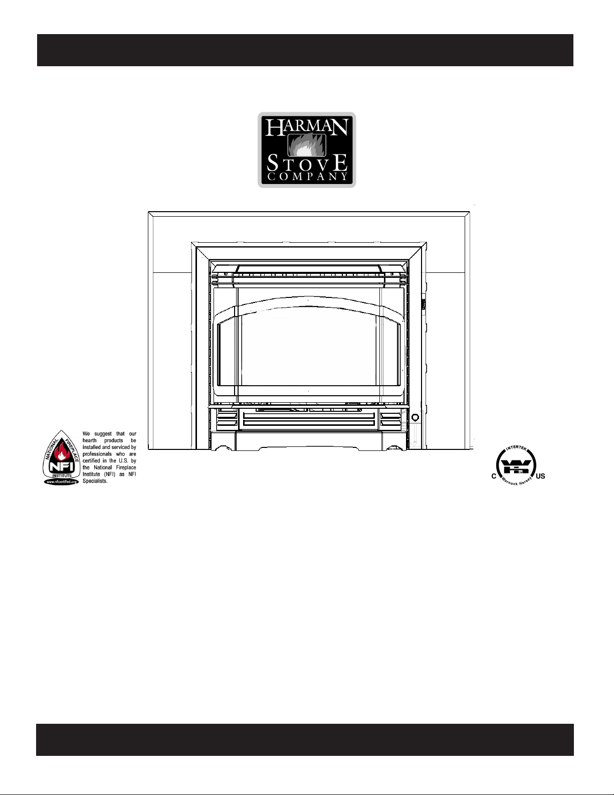
The Harman Clarity 828i Gas Fireplace Insert
“Ce manuel est disponible en Français sur demande”
SAFETY NOTICE
PLEASE READ THIS ENTIRE MANUAL BEFORE YOU INSTALL AND USE YOUR NEW ROOM HEATER. FAILURE
TO FOLLOW INSTRUCTIONS MAY RESULT IN PROPERTY
DAMAGE, BODILY INJURY, OR EVEN DEATH.
IF THIS HARMAN STOVE IS NOT PROPERLY
A HOUSE FIRE MAY RESULT. FOR YOUR SAFETY, FOLLOW
INSTALLATION DIRECTIONS.
CONTACT LOCAL BUILDING OR FIRE OFFICIALS ABOUT
RESTRICTIONS AND INSTALLATION INSPECTION
REQUIREMENTS IN YOUR AREA.
CONTACT YOUR LOCAL AUTHORITY (SUCH AS MUNICIPAL BUILDING DEPARTMENT, FIRE DEPARTMENT,
FIRE PREVENTION BUREAU, ETC.) TO DETERMINE THE
NEED FOR A PERMIT.
CETTE GUIDE D'UTILISATION EST DISPONIBLE EN
FRANCAIS. CHEZ VOTRE CONCESSIONNAIRE DE HARMAN STOVE COMPANY.
SAVE THESE INSTRUCTIONS.
INSTALLED,
R7
− FOR YOUR SAFETY: WHAT TO DO IF
YOU SMELL GAS
• Do not try to light any appliance.
• Open windows.
• Extinguish any open ame.
• Do not touch any electrical switch;
do not use any phone in your building.
Follow the gas supplier's instructions.
• If you can not reach your gas sup-
plier, call the re department.
Page 2
TABLE OF CONTENTS
INTRODUCTION ...........................................................3
INSTALLATION .............................................................4
Clearances .................................................................4
Venting .......................................................................7
Test for Flue Spillage ................................................8
ASSEMBLY ..................................................................... 5
Connecting to a Gas Supply ...................................... 8
Connecting the Cordset and Thermostat ................... 9
Installing into a Fireplace ........................................10
Air Shutter Adjustment ............................................11
Monitoring the Gas Flame ....................................... 11
OPERATION .................................................................12
How to Light the Fire .............................................. 12
How to Turn Off the Fire ......................................... 12
MAINTENANCE .......................................................... 13
Removing the Glass .................................................13
Replacing the Gasket ............................................... 13
Inspecting the Venting ............................................. 13
Cleaning the Glass ................................................... 13
Convection Blower Service Access..........................14
Reference Pictures ...................................................15
APPENDIX A: FUEL CONVERSION .........................16
APPENDIX B: ALTITUDE DE-RATING ...................17
APPENDIX C: CHANGING ORIFICES ...................... 18
APPENDIX D: WIRING DIAGRAM ........................... 19
PARTS LIST & DRAWING................................ 20-21-22
SPECIFICATIONS .......................................................23
WARRANTY .................................................................24
Manufactured by:
Harman Stove Co.
352 Mountain House Road
Halifax, PA 17032
Tested by
Intertek Testing/Warncok Hersey
8431 Murphy Drive
Middleton, WI 53562
2
Page 3

INTRODUCTION
The Harman Clarity 828I Vented Gas Fireplace
Insert is a listed, gas-red, vented room heater tested
by Intertek Testing Services/Warnock Hersey to ANSI
standard Z21.88-2002, CSA2.33-M02, and CAN/
CGA-2.17-M91.
The installation of the Clarity Fireplace Insert must
conform with local codes, or in the absence of local
codes, with National Fuel Gas Code, ANSI Z223.1
— latest edition (NFPA 54) and CAN 1 B1-149.1 and
.2 Gas Appliance Installation Code.
The Clarity Fireplace Insert is not for use in mobile
homes.
CAUTION: This appliance must be vented to the
outside.
Installation and repair of the Clarity Fireplace Insert
should be done by a qualied service person. The appliance should be inspected before use and at least
annually by a qualied service person. More frequent
cleaning may be required due to excessive lint from
carpeting, bedding material, etc. It is imperative that
control compartments, burners, and circulating air passageways of the appliance be kept clean. Any safety
screen or guard removed for servicing an appliance
must be replaced prior to operating the appliance.
When operating your Harman Clarity Fireplace In-
sert, respect basic safety standards.
Read these instructions carefully before you attempt
to operate the heater. Failure to do so may result in
damage to property or personal injury and may void
the product warranty.
Consult with your local building code agency and
insurance representative before you begin your installation to ensure compliance with local codes, including
the need for permits and follow-up inspections.
Observing required clearances to combustible materials, proper connection to an approved venting system,
and the accessibility of the gas and electrical supply
must all be considered when planning the installation
of the Clarity Fireplace Insert.
Adequate clearances around air openings to the combustion chamber and provisions for adequate combustion and ventilation air must be provided.
Install the Clarity Fireplace Insert only in a listed
solid-fuel burning factory-built replace or a masonry
solid-fuel burning replace. The Fireplace Insert and
vent should be enclosed when installed in, or when
passing through, a living area where children may
come in contact with it.
WARNING: If the information in this manual is not followed exactly, a re or explosion may
result causing property damage, personal injury or loss of life.
− FOR YOUR SAFETY
Do not store or use gasoline or other ammable vapors and liquids in the vicinity of this or
any other appliance.
Installation and service must be performed by a qualied installer, service agency, or the gas
supplier.
3
Page 4
INSTALLATION
IMPORTANT NOTICE
Due to high temperatures, the Clarity 828I
Vented Gas Fireplace Insert should be located
out of trafc and away from furniture and
draperies.
Children and adults should be alerted to the
hazards of high surface temperatures and should
stay away to avoid burns or clothing ignition.
Young children should be carefully supervised
when they are in the same room as the Clarity
828I Fireplace Insert.
Clothing or other ammable materials should
not be placed on or near the Clarity 828I
Fireplace Insert.
Suveiller les enfants. Garder les vêtements, les
meubles, l'essence ou autres liquides à vapeur
inammables lin de l'appareil.
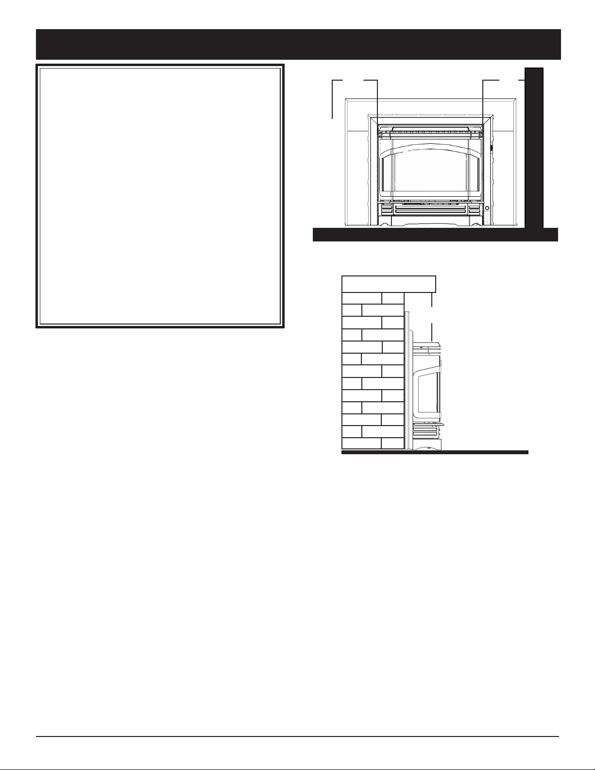
CLEARANCES
The following clearances to combustibles must be
observed:
10"
Clearance from unit to sidewall or combustible trim.
12"
10"
WALL
Unit to sidewall or
combustible trim ..........................10" (254 mm)
Unit to mantel and
combustible trim, unprotected ...12" (305 mm)
In addition to these clearances, adequate accessibility clearance for servicing and proper operation
must be maintained.
Do not, in any way, obstruct the combustion air
inlets that are located on the front of the heater.
Clearance from top of unit to mantel
and combustible trim, unprotected
4
Page 5
ASSEMBLY
The Clarity 828I Fireplace Insert comes with the
log set packed inside the rebox. The three trim
panels and two wing brackets are packed together in
a separate carton.
Right
Wing
Bracket
Left
Wing
Bracket
NOTE: The wing brackets must go on before
the door.
A second shipping carton contains the wing panels.
Two different size wing panel sets are available for
the Clarity Insert: large (32-1/2" X 44"), and small
(30" X 40"). The set that will work best with the
replace opening should be used. The wing panels
may be trimmed to t inside the replace opening if
a ush look is desired.
Before the unit is installed, all components should
be unpacked. The cross log must be removed, the
packing material taken out, and then re-installed.
The Clarity 828I is shipped from the factory
equipped to burn propane. If Natural Gas is to be
used, conversion kit # 1-00-09009 must be installed
at this time as well. See the fuel conversion instructions in Appendix A on page 16.
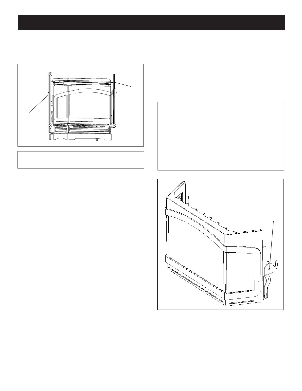
Removing the Glass door
NOTE: The glass door is heavy. Be prepared for
its weight when lifting it to avoid damage during
removal.
Locate latches on each side of the glass door. Then,
grasp each latch handle and pull forward until the
front is disengaged. Lift the glass door slightly and
remove it from the stove. Set the glass door aside in
a safe place where it will not be damaged.
WARNING: Do not abuse the glass on the
Clarity Fireplace Insert front by striking, slamming, or similar trauma. Do not operate this
Fireplace Insert with the glass panel removed,
cracked or broken. Use only glass supplied by
Harman and approved for use with this heater.
Do not use substitute materials. Replacement
of the panel should be done by a licensed or
qualied service person.
Latch
5
Page 6
ASSEMBLY
Removing and Replacing logs
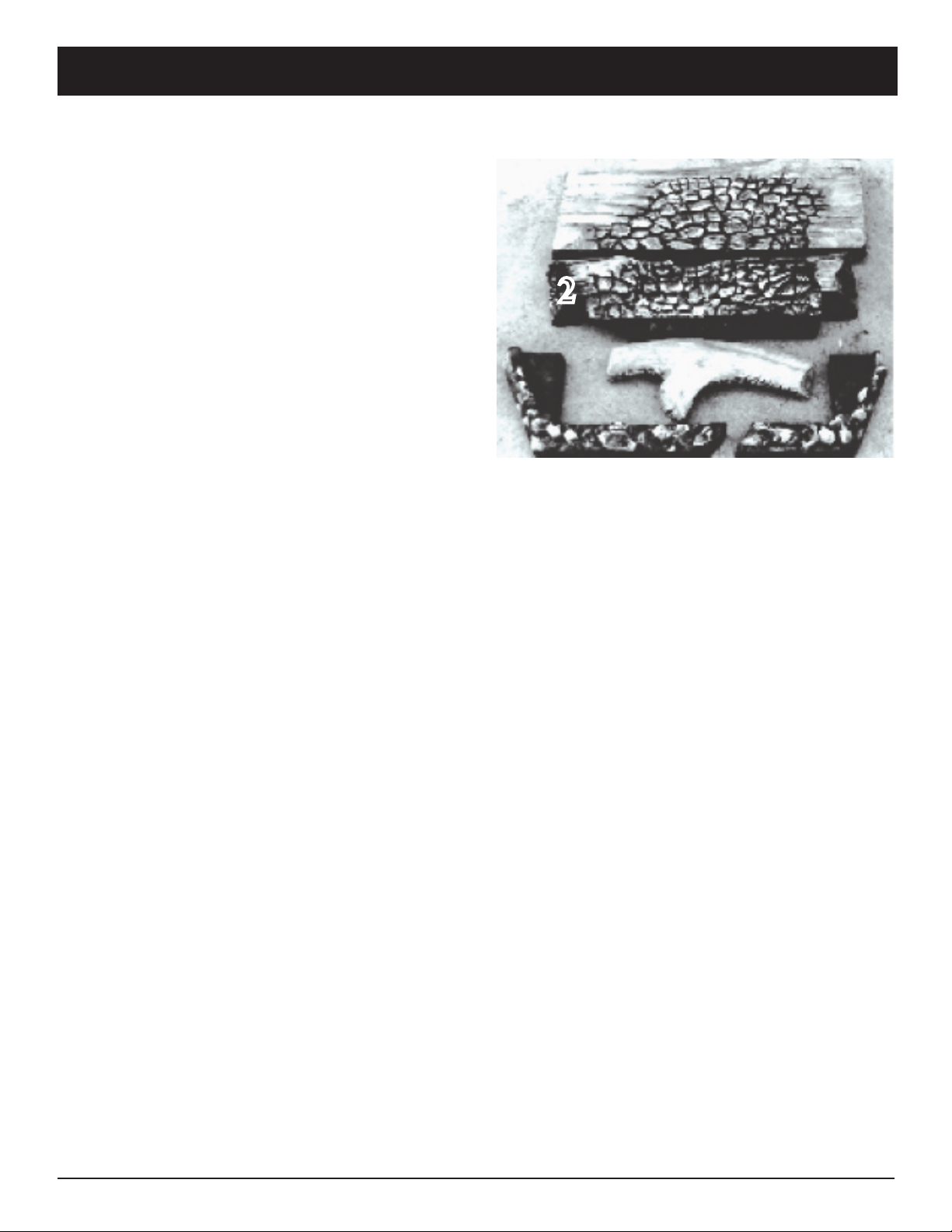
The log set consists of a back log (1), a center
log that has a pilot-viewing port in the left end (2),
2-piece ember strip (3), and a cross log that rests on
top (4).
Remove the cross log, the center log, and the em-
ber strips, in that order. To remove the rear log, rst
pull the fuel system module forward about an inch,
to create clearance, then lift the log out.
Re-install the logs in the same order that they were
removed. Place the rear log in position rst, centered
and pushed snugly against the back wall, and slide
the fuel system module back into position.
Re-install the ember strips so that they rest against
the front of the rebox. Guide them toward you and
to the outside until they t snugly. Check the air slot
inside from the ember strips to conrm that they do
not obstruct it.
Install the center log so that it goes all the way to
the back and is centered. When properly positioned,
there should be an even gap along the front of the
center burner in the cavity in the log. A small portion
of the log support frame will be revealed. The center
log has a round viewing port in the left end through
which the pilot can be observed.
Install the cross log, making sure that it is oriented
with the forked end toward the left rear of the stove,
and slip it over the front locator pin.
3
2
1
4
3
Re-install and Secure the Glass door
NOTE: The glass door is heavy. Lift it carefully to prevent damage. Center the glass on the
opening and suspend it in place by placing the
tab hooks over the top edge of the opening. Press
the glass slightly against the stove to conrm
that it seats properly, then press it rmly against
the front while pushing the levers to the rear to
engage them.
6
Page 7

Installation
INSTALLATION
PRELIMINARY STEPS TO PREPARE FOR
THE INSTALLATION OF THE CLARITY FIREPLACE INSERT
Remove the chimney cap if one exists so that the ue
may be cleaned and the venting installed.
Remove any existing hearth accessories such as glass
doors, spark screens, andirons, and grates.
Clean the chimney thoroughly to remove ash, soot,
and any obstructions, and then clean ash, soot, dust,
and debris from the replace.
The damper must be locked open to allow the 4"
venting to pass through. If it is necessary to modify
the damper area to allow passage of the venting, the
modications should be allowed under local codes.
Conrm any planned changes with local building ofcials.
Use Only Approved Venting
The Clarity 828I Vented Gas Fireplace Insert is
tested and listed for connection to a 4" (100 mm)
listed Class B venting system.
If the unit is installed to vent through an approved
masonry chimney or a factory-built chimney system,
a listed lining system approved for use with gas-red
appliances must be used.
Observe local codes when venting the Clarity. If
no local codes exist, follow the current edition of
ANSI Z223.1 and CAN1- B149 installation codes.
Do not connect the venting to the ue of a chimney
that serves a separate solid-fuel burning appliance.
The venting manufacturer's installation instructions must be followed exactly.
The Clarity Fireplace Insert is equipped with its
own integral draft hood so no additional draft hood
is required. The heater should be installed so that the
draft hood is in the same atmospheric pressure zone
as the air inlets to the heater.
The most efcient venting systems are those that
have a minimum number of bends and minimal horizontal runs.
The Clarity Fireplace Insert is equipped with a
thermally activated vent safety switch which will
shut down the main burner if the heater is not venting
properly. The safety switch will automatically reset
after the heater has cooled down.
The switch will continue to cycle off and on until
the venting problem is corrected. If you are unable to
correct the venting problem, seek expert advice from
your Harman dealer or installer.
DO NOT DISCONNECT OR BYPASS THE
VENT SAFETY SWITCH.
WARNING: Operation of this heater when
not connected to a properly installed and main-
tained venting system or tampering with the
vent safety shutoff system can result in carbon
monoxide (CO) poisoning and possible death.
IMPORTANT: Because of the high efciency
and low ue gas temperatures of this appliance, it
is important that it be connected to a well-sealed
and efcient venting system which is capable of
registering a negative pressure while the stove is
in operation.
7
Page 8
INSTALLATION
Test for Flue Spillage
A spillage test should always be made at the
completion of the installation, and at least annually
thereafter.
1. Start all exhaust fans in the home and then close
all doors and windows in the room containing the
heater.
2. Light the heater and allow it to run for 5 minutes
on the high output setting. The convection air blower
should be turned off for the test.
3. Remove the left trim panel, which is held in
place by a clip at the bottom and a magnet at the
top, and place a source of smoke (such as a match,
lighter, or a cigarette) in front of the ue spillage test
tube.
The smoke should be drawn into the tube. If it is
not, let the heater run for 5 more minutes and repeat
the test.
4. If the smoke is not drawn into the tube, turn off
the heater and determine why there is no draft. If
necessary, seek expert advice.
For sites with swirling or turbulent wind condi-
tions, a wind cap may solve the problem.
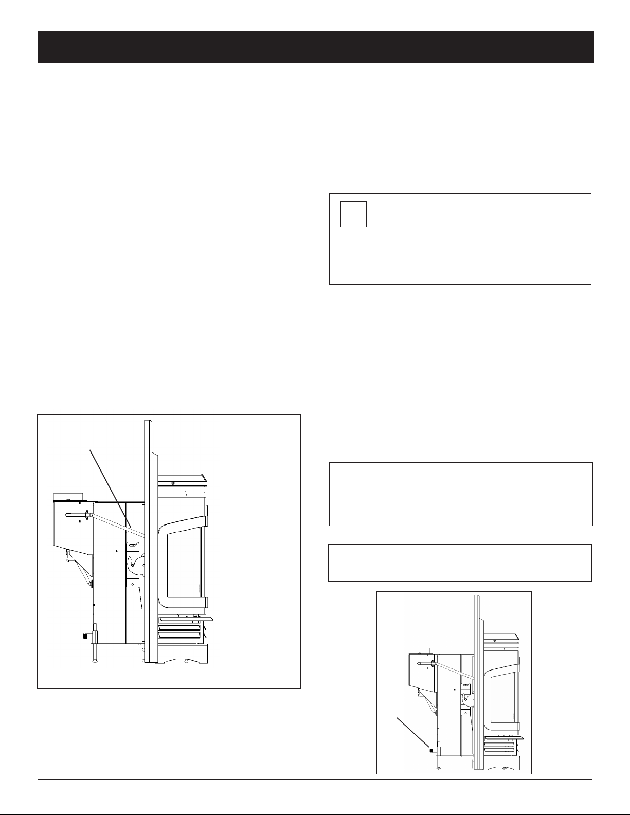
Draft Test Tube
Connecting the Clarity 828I Fireplace Insert to a Gas Supply.
Burn Only the Fuel for Which the Heater is Equipped.
The Clarity Fireplace Insert will burn either
natural gas or propane, but requires a conversion if
Natural Gas is to be burned. The label on the burner
system module indicates the fuel for which it is
equipped. The Prpoer box must be marked upon
installation or conversion.
NATURAL
PROPANE
Making The Connection
The gas inlet is located at the bottom right rear of the
Insert. The inlet tting is a 1/2" male pipe thread.
A separate gas shut-off valve and a 1/8" N.P.T. plugged
tapping should be installed immediately upstream of the
connection to the appliance.
The Clarity Fireplace Insert must be disconnected from
the gas supply piping during any pressure testing of that
system at pressures in excess of 1/2 psig (3.5 kPa).
The Clarity gas control valve must be in the OFF position during any pressure testing of the gas supply system
at pressures equal to or less than 1/2 psig (3.5 kPa).
Remove Left
Wing Cover to
Expose Draft
Test Tube.
WARNING: To avoid pipe compounds from
entering into the gas train, apply compounds
only to the male pipe threads and not to the
rst two threads.
CAUTION: TEST ALL PIPE JOINTS FOR
LEAKS BEFORE OPERATING
Inlet
8
Page 9

ASSEMBLY
Gas Pressure Requirements
Correct gas pressure and the use of a properly
sized gas supply line are essential for the safe and
efcient performance of this appliance. Make sure
that the plumber or gas supplier checks the gas supply line and gas pressure at installation.
NOTE: Improper gas pressure can affect heater
performance, ame color, or cause pilot outage.
Natural Gas:
Maximum inlet pressure 7.0" w.c. (1.74 kPa)
Minimum inlet pressure 5.0" w.c. (1.25 kPa)
Gas manifold pressure 3.5" w.c. (0.87 kPa)
LPG Gas:
Maximum inlet pressure 13" w.c. (3.24 kPa)
Minimum inlet pressure 11" w.c. (2.74 kPa)
Gas manifold pressure 10" w.c. (2.49 kPa)
DO NOT USE THIS HEATER IF ANY PART
HAS BEEN UNDER WATER OR EXPOSED TO
MOISTURE CORROSION. IMMEDIATELY
CALL A QUALlFlED SERVICE TECHNICIAN
TO INSPECT THE HEATER AND REPLACE
ANY PART OF THE CONTROL SYSTEM AND
ANY GAS CONTROL WHICH HAS BEEN UNDER WATER.
RECOMMENDED GAS PIPE DIAMETER
Pipe Length Schedule 40 Pipe Tubing, Type L
(Feet) Inside Diameter Outside Diameter
N.G. L.P. N.G. L.P.
0-10 1/2" 3/8" 1/2" 3/8"
1.3 cm 1.0 cm 1.3 cm 1.0 cm
10-40 1/2" 1/2" 5/8" 1/2"
1.3 cm 1.3 cm 1.6 cm 1.3 cm
Connecting the Cord Set
The Clarity Fireplace Insert, when installed, must
be electrically grounded in accordance with local
codes or, in the absence of local codes, with the
the current edition of the National Electrical Code,
ANSI/NFPA 70 in the United States or the current
Canadian Electrical Code CSA 22.1 in Canada.
This appliance is equipped with a three-prong
(grounding) plug for protection against shock hazard and should be plugged directly into a properly
grounded three-prong receptacle. Do not cut or
remove the grounding prong from the plug.
NOTE: The convection fan requires a 120 VAC
supply for operation, but the heater can be operated without the fan as in the case of a power
outage.
Plug the 3-prong grounded electrical cord plug into
the wall outlet.
Connecting the Optional Thermostat
If the optional thermostat is used, it must be
plugged into the terminal strip located behind the
right side of the air inlet grill. It can be accessed by
sliding open the control access drawer.
When installing a millivolt control system, use
only a special low resistance thermostat. Do not use
a regular heating thermostat.
Be sure that all electrical connections are clean,
free from corrosion, and tight. Inspect connections
periodically to conrm that no corrosion has occurred over time.
When properly installed and maintained, a millivolt control system should give many years of
trouble-free service.
It is important to use wire of a gauge proper for the
length of the wire:
40-100 1/2" 1/2" 3/4" 1/2"
1.3 cm 1.3 cm 1.6 cm 1.3 cm
100-150 3/4" 1/2" 7/8" 3/4"
2.0 cm 1.3 cm 2.3 cm 2.0 cm
NOTE: NEVER USE PLASTIC PIPE. CHECK TO CONFIRM
WHETHER YOUR LOCAL CODES ALLOW COPPER TUBING
OR GALVANIZED PIPE.
RECOMMENDED WIRE GAUGES
Maximum Length
100'
60'
40'
25'
15'
Wire Gauge
14
16
18
20
22
9
Page 10

ASSEMBLY
Installing the Insert Into the replace
The Clarity Fireplace Insert has an integrated draft
hood. Therefore, a separate draft hood is not required.
Some replace openings may be large enough to
connect the draft hood to the venting after the unit
has been moved to its nal position. Some openings
will be too small and will require that the draft hood
rst be connected to the venting, and then guided
into position on the top of the insert as the unit is
pushed back into the replace.
Particularly in installations with tight clearances,
the procedure will be most easily accomplished if the
trim and wing panels are installed as the last step.
Follow these steps:
1. Connect the Clarity Insert's detachable draft
hood to the end of the venting by sliding it inside the
venting, then secure it with three sheet metal screws.
Install the top wing panel last using two 1/4-20 fasteners. The mounting holes are near the inside edge
of the side wing panels. Before tightening, make sure
the outer edges of the top panel align with the edge
of the side panels. Brass edge trim is added as the
last step of installing the wing panels.
7. Mount the side trim panel, each is held in place
by two magnets. Install the left side trim panel rst
by placing the bottom close to where it goes, then
align the top and move it close to the insert body
until it is held snugly by the two magnets.
The right side trim panel installs in the same fashion as the left, but the wiring (Two Amp Mate-NLok connectors) that serves the On-Off switch at the
top of the panel and the blower speed control switch
on the bottom must be connected rst.
Move the right panel close enough to make the
connection. Align the three wire male connector
with the latch to the bottom. Push into the three
wire female connector on the stove until it clicks.
Do the same with the two wire connector with the
latch turned to the top. Move panel into place while
routing the switch wires into the opening of the wing
bracket. Secure the panel.
8. Install the top wing cover, which is also held in
place by the magnets.
9. Install the gold wing trim by sliding the side
pieces down from the top over each clip, one at a
time.
2. Line up the two draft hood guides with the
fourth heat exchanger tube from each side, as shown
above.
3. With assistance, push the insert back into the
replace, while at the same time guiding the draft
hood into position. Continue until both guides are
far enough forward that the retainer clamps and nuts
can be installed on the threaded guide bolts.
4. Tighten the nuts to secure the draft hood.
5. Adjust the rear levelling bolts until the unit is
level.
6. Install the wing panels; they attach to brackets
on each side of the Clarity. Install the side wing pan-
els rst, using two 1/4-20 fasteners for each panel.
Their mounting locations are near the top and bottom
of the panel.
10
Page 11

ASSEMBLY
Air Shutter Adjustment
The nal step of the installation is to check the
ame pattern, which should resemble the pattern il-
lustrated in the drawing in the next column.
The ames should be relatively well-dened and
stable. They should be bright yellow with a blue
base where attached to the burner ports, and should
not look orange or sooty.
Start the re according to the directions on page
12, and allow the heater to burn for approximately
15 minutes. The ames will increase in length and
become more yellow in color as the unit heats up.
Flame Adjustment Levers
Swing-out Label with Lighting
Instructions
Pilot ames will resemble those shown above
Monitoring the Gas Flame
Periodically, the ames of the Clarity Fireplace
Insert should be checked while it is in operation.
The ames should be well-dened and stable. They
should be bright yellow with a blue base where at-
tached to the burner ports. The ames should not
look orange or sooty. Portions of the logs will glow
red when the ames are properly adjusted.
If you nd the ames to be other than that de-
scribed here, do not operate the heater. Consult a
qualied service person or your Harman dealer for
advice.
Three adjustment levers, one for each burner, are
used to adjust the ames for each particular installation. They are accessible when the front control
access drawer is opened. The levers may become hot
to the touch after prolonged operation. Use a glove
to avoid contact if hot. For best results, when netuning the ame picture, initially leave the middle
lever unchanged from its factory setting. Move the
other two levers as needed to increase or decrease
the brightness and length of the ame: moving left
will increase the ame; moving right will decrease
the ame.
11
Page 12

OPERATION
How to Light the Fire
1. STOP! Read the safety information on the
lighting instructions label on the stove.
2. If using the optional thermostat, set thermostat
to the lowest setting.
3. Turn off electric power to the appliance.
4. Turn the ON-OFF/THERMOSTAT switch to
the OFF position.
5. Push in the gas control knob slightly and turn it
clockwise to "OFF."
NOTE: The knob cannot be turned from "PILOT"
to "OFF" unless it is pushed in slightly. Do not
force it.
6. Wait ve (5) minutes to clear out any gas. If
you then smell gas, STOP! Follow "B" in the safety
information on the swing-out label. If you don't
smell gas, go to the next step.
7. Set the High-Low Regulator to High by turning
it fully counterclockwise.
8. Press in the gas control knob slightly and turn
counterclockwise to "PILOT."
9. Find the pilot by looking through the round
opening on the left end of the center log.
10. Push the control knob fully down and hold.
Immediately push the red piezo ignitor button to
light the pilot. It is normal to have to push the red
button several times before the pilot ignites. Continue to hold the control knob in for about one (1)
minute after the pilot is lit. Release the knob and it
will pop back up. Pilot should remain lit. If it goes
out, repeat steps 5 through 9.
• If the knob does not pop up when released, stop
and immediately call your service technician or gas
supplier.
• If the pilot will not stay lit after several tries,
turn the gas control knob to "OFF" and call your
service technician or gas supplier.
11. Turn the gas control knob counterclockwise to the "ON" position.
12. Place the ON-OFF/THERMOSTAT switch in
the "ON" position or in the "THERMOSTAT" position if the optional thermostat is used.
13. Turn on the electric power to the heater.
14. Set the optional thermostat to the desired
room temperature.
15. Set the High-Low Regulator to desired setting:
turn fully counterclockwise for High and fully clockwise for Low.
Hi/Low Regulator
On/Off/Pilot Knob
NOTE: An odor resulting from the initial heating of new materials in your heater is not unusual
during the rst re, and in most cases will disappear after an hour or two.
How to Turn Off the Fire
1. If using an optional thermostat, set thermostat to
the lowest position.
2. Turn off the electric power to the appliance.
3. Turn the ON-OFF/THERMOSTAT switch to the
OFF position.
4. Push in the gas control knob slightly and turn it
clockwise to “OFF.”
NOTE: The knob cannot be turned from “PILOT”
to “OFF” unless it is pushed in slightly.
Do not force it.
●FOR YOUR SAFETY: WHAT TO DO IF YOU
SMELL GAS
• Do not try to light any appliance.
• Open windows.
• Extinguish any open ame.
• Do not touch any electrical switch; do not
use any phone in your building. Follow the gas
supplier's instructions.
• If you can not reach your gas supplier, call the
re department.
12
Page 13

MAINTENANCE
Maintenance
A qualied service person recommended by your
Harman dealer should conduct an annual inspection
and maintenance of your Clarity, its venting, and the
installation to keep it running safely and efciently.
These procedures should be performed only by a
qualied service person. The gas supply should be
turned off whenever a maintenance procedure is
performed.
Any access panels that are removed for servicing
must be replaced prior to operating the Clarity 828I
Vented Gas Fireplace Insert.
Inspecting the Venting
An inspection of the venting system should be
made during the annual service appointment to con-
rm that there is no blockage and that the system is
in good repair. Directions for conducting a ue spill-
age test may be found on page 8. The vent manufac-
turer's instructions may provide specic suggestions
or details on vent inspection. Any sections that are
taken apart for the inspection must be reassembled
and sealed as required.
Replacing the Gasket
The Clarity has 5/8" diameter berglass gasket
around the glass door. Should it ever need replacement, use only the proper replacement gasket that is
available from your Harman dealer. To replace the
gasket, follow this procedure.
1. Remove the front according to directions above.
2. Remove the existing gasket and clean its channel
with a scraper or wire brush.
3. Lay a thin bead of high temperature silicone the
entire length of the channel.
4. Place the gasket in the channel with sufcient
pressure that it stays in place.
5. Trim the excess from the end of the gasket so
that it butts snugly against the other end without
leaving a gap. Seal the end joint with high temperature silicone.
6. Close the door and apply rm pressure to seat
the gasket evenly.
Cleaning the Glass
The glass may be cleaned with ordinary household
glass cleaner and a soft cloth or paper towel.
Removing the Glass door and Trim Panels
To gain access to the latches that secure the door,
rst remove the two side trim panels. Each is held in
place by a magnet at the bottom and a magnet at the
top.
Remove the left side trim panel rst by pulling the
top slightly away from the unit, and then litng.
The right side trim panel is removed in the same
fashion as the left, but is tethered to the Insert by the
wiring that serves the On-Off switch at the top and
the blower speed control switch on the bottom.
Disengage the right side panel, then pull gently on
it to create enough space so that you can reach the
latch that holds the door. If more space is needed to
gain access to the latches, reach inside and disconnect the wiring (Two Amp Mate-N-Lok connectors).
The trim panel will then come away from the unit.
WARNING: Never clean the glass when it is
hot. Do not use abrasive cleaners on the glass.
CAUTION: If the door is opened or removed for
servicing, it must be replaced and closed securely
prior to operating the appliance. The glass must
also be xed securely in the door when operating
the appliance.
13
Page 14

MAINTENANCE
Cleaning the Log Set and Firebox
During the annual inspection and maintenance
appointment, the service person should clean dust,
lint, and any light accumulation from the logs and
the rebox area. An extra-soft brush should be used
on the logs as they are extremely fragile; a vacuum
cleaner may be used on the rebox. If at any time the
logs cannot be removed or installed without forcing,
the cause must be found. The logs must never be
forced. Follow this sequence:
1. Remove the side trim panels according to the
directions on page 13.
2. Remove the glass door according to the direc-
tions on page 13.
3. Remove, clean, and re-install the log set, observing the directions on log handling and placement
found on page 6.
Convection Blower Service Access
The blower is located behind a panel that can be
accessed by rst removing the fuel module. See page
22. Remove the two fasteners securing the panel
and pull the panel forward. The blower will come
out with the panel. Disconnect the blower electrical
connector to completely remove the blower from the
unit.
14
Page 15

MAINTENANCE
15
Page 16

Appendix A: Fuel Conversion
THE HARMAN CLARITY GAS INSERT IS
BUILT FOR USE WITH PROPANE.
Natural Gas conversion kit # 1-00-09009, available
only from the Harman Stove Company, is necessary
to complete the fuel conversion. This kit includes,
NG regulator knob assembly, Pilot orice, three
burner orices, Instructions, and a conversion label,
which must be afxed to the valve upon completion
NOTE: THE CONVERSION SHALL BE CARRIED OUT IN ACCORDANCE WITH THE REQUIREMENTS OF THE PROVINCIAL OR LOCAL
AUTHORITIES HAVING JURISDICTION AND IN
ACCORDANCE WITH REQUIREMENTS OF THE
CURRENT EDITION OF THE NATIONAL FUEL
GAS CODE, ANSI Z223.1 or the CAN/CGA-B149
INSTALLATION CODES.
CAUTION: LABEL ALL WIRES PRIOR
TO DISCONNECTION WHEN SERVICING CONTROLS. WIRING ERRORS CAN
CAUSE IMPROPER AND DANGEROUS
OPERATION. VERIFY PROPER OPERATION AFTER SERVICING.
IMPORTANT: Perform a leak test upon com-
pletion of the fuel conversion.
SEE WIRING DIAGRAM ON PAGE 19
NATURAL
PROPANE
Steps for completing the fuel conversion:
Prior to installing the fuel conversion, remove
the Glass door and the log set, to gain access to the
burner module. Remove the burner tubes by sliding
to the left while lifting upward. Remove the burner
cover plate and the tube box top as shown.
Step 1: Remove pilot hood with a 7/16" wrench.
Inside, you will nd and discard the Propane orice. Install the new Natural Gas orice from the kit.
Tighten the pilot hood and assure proper alignment
of the directional openings.
Step 2: Using a 1/2 in. deep-well socket, remove
the three main burner orices. Install the new orices accordingly; Front = #47, Middle = #56, Rear =
#44. Apply a thread sealer such as teon tape, to the
orices prior to installing. (See Appendix C)
Step 3: Using a small at-blade screwdriver, re-
move the three screw that hold the LP knob module
in place. Remove the module and replace it with the
Natural Gas module from the kit. See kit instructions.
Step 4: Afx the conversion label to the valve so
that any future service tech etc... can plainly see that
the valve was converted.
Step 5: Mark the appropriate fuel box on the unit
label, pictured at left, using a permanent marker.
16
Page 17

Appendix B: De-rating for High Altitude
For U.S. installations, the Clarity Fireplace Insert
is approved for elevations up to 2000 feet using
the factory-installed burner injectors. At elevations
above 2000 feet, U.S. codes require a decrease in
the input rating by changing the burner injectors to a
smaller size. The chart below lists by part numbers
the appropriate injectors for both LP and natural gas
at various altitudes.
For Canadian installations, the Clarity Fireplace
Insert is approved for elevations up to 1370 meters
(4500 feet).
NATURAL GAS
Front Harman Center Harman Rear Harman Nominal Btu
Altitude Injector Part No. Injector Part No. Injector Part No. Input Rate
0-2000' 47 3-40-64347 56 3-40-57356 44 3-40-25844 40,000
2000-3000' 47 3-40-64347 56 3-40-57356 45 MALE 38,400
3000-4000' 48 MALE 56 3-40-57356 45 MALE 36,900
4000-5000' 49 MALE 56 3-40-57356 46 MALE 35,400
5000-6000' 49 MALE 57 3-40-25857 47 3-40-64347 34,000
6000-7000' 50 MALE 57 3-40-25857 47 3-40-64347 32,600
7000-8000' 50 MALE 58 MALE 48 MALE 31,300
8000-9000' 51 MALE 58 MALE 48 MALE 30,100
For high altitude installations above 1370 meters
(4500 feet), consult the local gas distributor or the
authority having jurisdiction for proper rating methods.
NOTE: The difference in altitude derating requirements for the U.S. and Canada is simply a result
of differences in testing standards between the two
countries.
If the installer must convert the unit to adjust for
varying altitudes, an information sticker like the one
below must be lled out and afxed to the appliance
at the time of conversion.
PROPANE
Front Harman Center Harman Rear Harman Nominal Btu
Altitude Injector Part No. Injector Part No. Injector Part No. Input Rate
0-2000' 57 3-40-25857 71 3-40-57271 55 3-40-25855 40,000
2000-3000' 59 MALE 71 3-40-57271 55 3-40-25855 36,900
3000-4000' 57 3-40-25857 71 3-40-57271 56 3-40-57356 36,900
4000-5000' 58 MALE 71 3-40-57271 56 3-40-57356 35,400
5000-6000' 59 MALE 71 3-40-57271 56 3-40-57356 32,600
6000-7000' 59 MALE 71 3-40-57271 57 3-40-25857 32,600
7000-8000' 60 MALE 71 3-40-57271 57 3-40-25857 30,100
8000-9000' 61 MALE 71 3-40-57271 58 MALE 30,100
THE CONVERSION SHALL BE CARRIED OUT BY A MANUFACTURER'S
AUTHORIZED REPRESENTATIVE IN
ACCORDANCE WITH THE REQUIRE-
MENTS OF THE MANUFACTURER,
PROVINCIAL OR TERRITORIAL
AUTHORITIES HAVING JURISDICTION AND IN ACCORDANCE WITH
THE CURRENT EDITION OF THE
REQUIREMENTS OF THE CAN/CGAB141.1 OR CAN/CGA-B141.2 INSTAL-
LATION CODES
This appliance has been converted for use at an altitude of __________ft.
Orice Sizes: Front ________ Center_________ Rear ________
Input (Btu/hr) _________________
Manifold Pressure __________________
Fuel Type _______________________
Converted By _________________________________
Date of Conversion _______________________________
When ordering injectors with no item number,
*
specify MALE or FEMALE and the 2-digit size
number.
17
Page 18

Appendix C: Changing Orices
To change the orices, such as when derating for
altitude, follow these steps.
1. Remove the side trim panels according to the directions on page 13 to gain access to the levers that
secure the glass door, then remove the glass door
according to the directions on page 5.
2. Disconnect the electrical connections and the
gas line tting from the fuel module.
3. Remove the cross log, the front logs, and the
two ember strips following the directions on page 6.
4. Pull the module out an inch or so so that there is
enough room to remove the rear log.
5. Remove the burner system module.
6. Pull the top tray forward so that it disengages;
lift the front edge up, then remove it.
HARMAN CLARITY GAS
FIREPLACE INSERT
8. Remove the center burner.
9. Remove the front burner.
10. Remove the 1/4-20 fasteners and retainer clip
that secure the rear burner, then remove the rear
burner.
11. Lift the rear air deector straight up, and rock it
forward.
12. Remove the orice compartment cover; (before
it can be removed, it may be necessary to use pliers to straighten the tab that goes through the T-slot,
which holds the cover in place. Pull the cover to the
left and lift it out. The orices will now be visible).
13. Lift the orice compartment dividers straight
up to remove them for better access. When you reinstall the dividers, make sure they are seated all the
way in to prevent air leakage from one compartment
to another.
14. Re-install all components in the reverse order
that they were removed.
This Appliance is equipped for NATURAL GAS fuel.
Cet appareil a ete converti au GAZ NATUREL .
Injectors/Injecteur:
Input/Debit calorique:
Manifold Pressure /
Pression a la tubulure d’alimentation:
Inlet Pressure /
Pression D’arrivée:
Date module installed:
By:
Front Center Rear
DMS 47
Min.
Max.
DMS 56
DMS 39
40,000
3.5
5.0
7.0
18
Page 19

Appendix D: Low Voltage Wiring Diagram
120 Volt Wiring Diagram
The Clarity Fireplace Insert, when installed, must be electrically grounded in accordance with local codes or, in the
absence of local codes, with the current edition of the National Electrical Code, ANSI/NFPA 70 in the United States or
the current Canadian Electrical Code CSA 22.1 in Canada.
19
Page 20

PARTS LIST
The following replacement parts for your Harman Clarity Fireplace Insert are available from your Harman dealer.
1. Pilot NG 3-40-09011
Pilot LP 3-40-09010
2. Thermopile 3-20-08219
3. Pilot Tube 2-00-446118
4. Thermocouple 3-40-08906
5. Piezo Ignitor 3-40-08220
6. Ignitor Cable 3-40-08231
7. Pilot Bracket 2-00-446134
8. Tube Box Top 2-00-446110
9. Rear Orice(NG) #44 3-40-25844
Rear Orice (LP) #55 3-40-25855
10. Center Orice (NG) #56 3-40-57356
Center Orice (LP) #71 3-40-57271
11. Front Orice (NG) #47 3-40-25847
Front Orice (LP) #57 3-40-25857
12. Divider Plates (2) 2-00-446108
13. Burner Weldment 1-10-08575
14. Air Dam 2-00-446132
15. Valve Heat Shield 2-00-446135
16. Valve (NG) 3-40-820628
Valve (LP) 3-40-82057
17. Valve Door Magnet 3-31-08225
18. 3/8 pipe x 3/8 comp. L 3-31-08567
19. L Tube 2-00-08586
20. 3/8 pipe x 3/8 comp. 3-31-08284
21. 1/4 pipe x 3/8 comp. L 3-31-08566
22. S Tube Flex 3-40-8618
23. Label
24. Rear Air Adjuster 2-00-446113
25. Center Air Adjuster 2-00-446112
26. Front Air Adjuster 2-00-446111
27. Front Burner Tube 3-40-08224
28. Center Burner Tube 3-40-08225
29. Rear Burner Tube 3-40-08226
30. Burner Plate 1-10-08577
31. 1/4-20x5/8 Self Tap 3-30-1252006216
32. Burner Retainer 2-00-4211
33. 1/4-20x1 bolt 3-30-1252010013
34. Air Deector 1-10-08576
35. Door (without frame) 1-10-08587
Arch Frame 1-00-446303
Sunrise Frame 1-00-446304
36. Burner Module (NG) 1-10-08700
Burner Module (LP) 1-10-08800
37. Gold Bars (2) 4-40-00141
Bar Holders (Left) 2-00-446300-1
Bar Holder (Right) 2-00-446300-2
38. Retainer Clips (2) 2-00-446322
39. Blower Assembly 1-10-08594
40. Valve Door 1-00-08592
41. U Bolt 3-31-08568
42. Pipe Nipple 13 1/2" 3-50-08570
43. 1/4 pipe x 3/8 comp. L 3-31-08566
44. 1/4" Coupling 3-10-3001025
45. Air Inlet Grill 1-10-08593
46. Latch Plate (2) 2-00-446315
47. Right wing 2-00-446313
48. Right Wing Cover 1-10-08593
49. Right Wing Bracket 2-00-446306
50. Flue Switch Bracket 2-00-446326
51. Stove Body Weldment 1-89-08700
52. Insulation 3-44-08562
53. Stove Top 1-10-08595
54. Draft Tube 2-00-446327
55. Draft Hood Weldment 1-10-08579
56. Vent Flange (std.) 1-10-08591
57. Flue Adaptor (optional) 1-10-08601
58. Top Wing 2-00-446312
59. Top Wing Cover 2-00-446308
60. Left Wing Bracket 2-00-446307
61. Left Wing Cover 2-00-446309
62. Left Wing 2-00-446311
63. Side Cover 1-10-08593
64. Hood Retainer 1-10-08590
65. Base 2-00446323
20
Page 21

EXPLODED VIEW
Burner Assembly
34
32
31
33
30
27
28
29
16
15
2
1
12
7
8
9
10
11
26
25
24
6
3
5
4
13
17
23
20
22
18
19
21
21
Page 22

EXPLODED VIEW
22
Page 23

SPECIFICATIONS
Tested to ANSI Z21.88-2002, CSA 2.33-M02,
CAN/CGA 2.17-M91.
NATURAL GAS PROPANE
Input Rating (Btu/hr) (0-1370 m) 37,000 37,000
Min. Input Rating (Btu/hr) (0-1370 m) 25,000 27,500
Injector Sizes (DMS) (front/center/rear (0-1370 m) 47/56/44 57/71/55
Manifold Pressure (in w.c./kPa) 3.5/0.87 10.0/2.49
Minimum Manifold Pressure (in w.c./kPa) 1.7/0.42 5.9/1.47
Minimum Inlet Pressure (in w.c./kPa) 5.0/1.25 11.0/2.74
Maximum Output (Btu/hr) (0-1370 m) 27,600 28,400
AFUE (seasonal efciency; minimum venting) 64.9% 67.0%
Steady State Efciency (max. input, blower on High) 77.2% 78.6%
MINIMUM CLEARANCES FROM COMBUSTIBLE CONSTRUCTION
Unit to side wall or combustible trim ....................................10 in. (254 mm)
Unit to mantel and combustible trim, unprotected ................12 in. (305 mm)
Electrical Rating: 120 Volts, 60 Hz., 1.2 Amp
30 (opt)
32.5 (std)
44 (std.)
40 (opt.)
23
Page 24

HARMAN GOLD WARRANTY
HARMAN GOLD WARRANTY
6 YEAR TRANSFERABLE LIMITED
WARRANTY (Residential)
1 YEAR LIMITED WARRANTY (Commercial)
Harman Stove Company warrants its products to be free from defects in material or workmanship, in normal use and
service, for a period of 6 years from the date of sales invoice and for mechanical and electrical failures, in normal use and
service, for a period of 3 years from the date of sales invoice.
If defective in material or workmanship, during the warranty period, Harman Stove Company will, at its option, repair or
replace the product as described below.
The warranty above constitutes the entire warranty with respect to Harman Stove Company products. HARMAN STOVE
COMPANY MAKES NO OTHER WARRANTY, EXPRESSED OR IMPLIED, INCLUDING “ANY” WARRANTY
OF MERCHANTABILITY, OR WARRANTY OF FITNESS FOR A PARTICULAR PURPOSE. No employee, agent,
dealer, or other person is authorized to give any warranty on behalf of Harman Stove Company. This warranty does not
apply if the product has been altered in any way after leaving the factory. Harman Stove Company and its agents assume
no liability for “resultant damages of any kind” arising from the use of its products. In addition, the manufacturer and its
warranty administrator shall be held free and harmless from liability from damage to property related to the operation, proper
or improper, of the equipment.
THERE ARE NO WARRANTIES WHICH EXTEND BEYOND THE DESCRIPTION ON THE FACE HEREOF.
THESE WARRANTIES APPLY only if the device is installed and operated as recommended in the user’s manual.
THESE WARRANTIES WILL NOT APPLY if abuse, accident, improper installation, negligence, or use beyond rated
capacity causes damage.
HOW TO MAKE A CLAIM - Any claim under this warranty should be made to the dealer from whom this appliance
was purchased. Then contact is made with manufacturer, giving the model and serial numbers, the date of purchase, your
dealer’s name and address, plus a simple explanation of the nature of the defect. Extra costs such as mileage and overtime
are not covered. Nuisance calls are not covered by these warranties.
THIS WARRANTY IS LIMITED TO DEFECTIVE PARTS - REPAIR AND/OR REPLACEMENT AT HARMAN STOVE COMPANY’S OPTION AND EXCLUDES ANY INCIDENTAL AND CONSEQUENTIAL DAMAGES CONNECTED THEREWITH.
WARRANTY EXCLUSIONS: Failure due, but not limited to, re, lightning, acts of God, power failures and/or surges,
rust, corrosion and venting problems are not covered. Damage and/or repairs including but not limited to; remote controls,
lters, fuses, knobs, glass, ceramic brick panels, ceramic ber afterburners, door packing, tile, ceramic log sets, paint, batteries or battery back-up and related duct work are not covered. Also excluded from this warranty are consumable or normal
wear items including but not limited to; ame guides, grates, coal bars, afterburner hoods, re brick, gaskets. Additional
exclusions for corn stoves are burnpot housing weldment, burnpot grate weldment (pellet or corn), burnpot front plate (pellet
or corn), burnpot front plate lock, corn auger extension, ceramic insert, and ceramic insert plate. Additional or unusual utility
bills incurred due to any malfunction or defect in equipment and the labor cost of gaining access to or removal of a unit that
requires special tools or equipment are not covered. Maintenance needed to keep the stove in “good operating condition” is
not covered. This includes, but is not limited to, cleaning, adjustment of customer controls and customer education. Labor,
materials, expenses and/or equipment needed to comply with law and/or regulations set forth by any governmental agencies
are not covered.
This Warranty provides specic legal rights and the consumer may have other rights that vary from state to state.
In the event of change in ownership, the remaining portion of this warranty may be transferred to the new owner by sending the new owner information and a transfer fee of $25.00 US to the Harman Stove Company.
PLEASE READ THE LITERATURE BY THE MANUFACTURER FOR THE VARIOUS ACCESSORY DEVICES.
THE MANUFACTURER WARRANTS THESE ACCESSORY DEVICES, NOT HARMAN STOVE COMPANY
OR THEIR WARRANTY ADMINISTRATOR. FURTHERMORE, THESE ACCESSORY DEVICES MUST BE INSTALLED AND USED ACCORDING TO THE RECOMMENDATIONS OF THE MANUFACTURER.
REMEDIES - The remedies set forth herein are exclusive and the liability of seller with respect to any contract or sale or
anything done in connection therewith, whether in Contract, in tort, under any warranty, or otherwise, shall not, except as
herein expressly provided, exceed the price of the equipment or part of which such liability is based.
CLARIFY - The above represents the complete warranty, which is given in connection with stoves, manufactured by Harman
Stove Company. No other commitments, verbal or otherwise, shall apply except by a written addendum to this warranty.
24
 Loading...