

Page 1
Installation & Operating Manual
The Harman Clarity 929 DV
Direct Vent Gas Stove
1
“Ce manuel est disponible en Français sur demande”
This appliance may be installed in an aftermarket, permanently located, manufactured home (USA only) or mobile home,
where not prohibited by local codes. This appliance is only for use with the type of gas indicated on the rating plate. This
appliance is not convertible for use with other gases, unless a certied kit is used.
Cet appareil peut être installé dans une maison préfabriquée (mobile) déjà installée à demure si les règlements locaux
le permettent. Cet appareil doit être utilisé uniquement avec le type de gaz indiqué sur la plaque signalétique. Cet appareil ne peut être converti à d'autres gaz, sauf si une trousse de conversion est utilisée.
WARNING: If the information in these instructions
are not followed exactly, a re or explosion may
result causing property damage, personal injury or
loss of life.
Installation and service must be performed by a quali-
ed installer, service agency, or the gas supplier. Do
not store or use gasoline or other ammable vapors
and liquids in the vicinity of this or any other appliance.
SAVE THESE INSTRUCTIONS.
WHAT TO DO IF YOU SMELL GAS
• Do not try to light any appliance.
• Do not touch any electrical switch; do not use
any phone in your building.
• Immediately call your gas supplier from a
neighbor's phone. Follow the gas supplier's instructions.
• If you cannot reach your gas supplier, call the
re department.
#3-90-08290
R10
Page 2
2
INTRODUCTION...............................................3
INSTALLATION ................................................4
Clearances ...............................................4
Venting ....................................................5
Terminating the Venting ........................6
Approved Venting Parts................8-14
Assembly...........................................15
Connecting to a Gas Supply ................17
Connecting the Cordset .......................18
Connecting the Thermostat .................18
Air Shutter Adjustment .......................19
Monitoring the Gas Flame ..................19
OPERATION .....................................................20
How to Light the Fire ..........................20
How to Turn Off the Fire.....................20
Lighting Instructions ...........................21
MAINTENANCE ..............................................22
Removing the Glass .............................22
Replacing the Gasket ...........................22
Cleaning the Glass ...............................22
Inspecting the Venting .........................22
Cleaning the Logset and Firebox ........22
PARTS LIST & DRAWING ....................... 24-26
SPECIFICATIONS ...........................................27
APPENDIX A: FUEL CONVERSION ...........28
APPENDIX B: ALTITUDE DE-RATING .....29
WARRANTY.................................................30
CONTENTS
This appliance is also approved for installation into a shop.
Manufactured by:
Harman Home Heating
352 Mountain House Road
Halifax, PA 17032
Tested by
Intertek/Warnock Hersey
8431 Murphy Drive
Middleton, WI 53562
Page 3
INTRODUCTION
3
The Harman Clarity Direct Vent 929DV Gas Heater is a
listed gas-red direct vent room heater tested by Inchcape
Testing/Warnock Hersey to standard ANSI Z21.88-2002CSA 2.33-2002, and CAN/CGA-2.17-M91.
The installation of the Clarity Direct Vent Gas Heater must
conform with local codes, or in the absence of local codes,
with National Fuel Gas Code, ANSI Z223.1 — latest edition
and CAN 1 B1-149.1 and .2 Installation Code.
Also for use in mobile (manufactured) homes after home
is sited.
Mobile (manufactured) home installations must adhere
to the current edition of Title 24 CFR, part 3280, or CSA
Z240.4.
CAUTION: This appliance must be vented to the outside.
Installation and repair of the Clarity Direct Vent Gas
Heater should be done by a qualied service person. The appliance should be inspected before use and at least annually
by a qualied service person. More frequent cleaning may
be required due to excessive lint from carpeting, bedding
material, etc. It is imperative that control compartments,
burners, and circulating air passageways of the Clarity be
kept clean.
When operating your Harman Clarity Gas Heater, respect
basic safety standards. Read these instructions carefully
before you attempt to operate the heater. Failure to do so
may result in damage to property or personal injury and may
void the product warranty.
Consult with your local building code agency and insurance representative before you begin your installation to
ensure compliance with local codes, including the need for
permits and follow-up inspections.
Several issues must be addressed when selecting a suitable
location for your Clarity Gas Heater. Observing required
clearances to combustible materials, the proximity to a safe
chimney or venting system location, and the accessibility
of the gas and electrical supply must all be considered. In
addition, selecting a location that takes advantage of the
building's natural air ow is also desirable to maximize the
heating effectiveness of the heater. In many cases, this is a
central location within the building.
SAFETY NOTICE
PLEASE READ THIS ENTIRE MANUAL BEFORE YOU INSTALL AND USE YOUR NEW ROOM HEATER. FAILURE
TO FOLLOW INSTRUCTIONS MAY RESULT IN PROPERTY DAMAGE, BODILY INJURY, OR EVEN DEATH.
FOR USE IN THE U.S. AND CANADA. SUITABLE FOR INSTALLATION IN MOBILE HOMES
IF THIS HARMAN STOVE IS NOT PROPERLY
LOW INSTALLATION DIRECTIONS.
CONTACT LOCAL BUILDING OR FIRE OFFICIALS ABOUT RESTRICTIONS AND INSTALLATION INSPECTION
REQUIREMENTS IN YOUR AREA.
CONTACT YOUR LOCAL AUTHORITY (SUCH AS MUNICIPAL BUILDING DEPARTMENT, FIRE DEPARTMENT,
FIRE PREVENTION BUREAU, ETC.) TO DETERMINE THE NEED FOR A PERMIT.
CETTE GUIDE D'UTILISATION EST DISPONIBLE EN FRANCAIS. CHEZ VOTRE CONCESSIONNAIRE DE HARMAN HOME HEATING.
ADVETISSEMENT: Quinconque ne respect
pas à la lettre les instructions dans le
présent manuel risque de déclencher un incendie ou une explosion entraíant des dommages matérials, des lésions corporelles ou
la perte de vies humaines. Installation ou
modication, consulter le manuel des usagers fourn avec ce génerateur d'air chaud.
Ne pas entreposer ni utiliser d'essence ni
d'autres vapeurs ou liquides inammables
dans le voisinage de cet appareil ou de tout
autre appareil.
INSTALLED, A HOUSE FIRE MAY RESULT. FOR YOUR SAFETY, FOL-
POUR VOTRE SÉCURITÉ: Que faire si vous
sentez une odeur de gaz:
• Ne pas tenter d'allumer d'appareil.
• Ne touchez à aucun interrupteur. Ne pas
vous servir des téléphones se trouvant dans
le batiment où vous trouvez.
• Evacuez la pièce, le bâtiment ou la zone.
• Appelez immédiatement votre fournisseur
de gaz depuis un voisin. Suivez les instructions du fournisseur.
• Si vous ne pouvez rejoindre le fournisseur
de gaz, appelez le service dos incendies.
Page 4
4
INSTALLATION
IMPORTANT NOTICE
Due to high temperatures, the Clarity Direct Vent
Gas Heater should be located out of trafc and away
from furniture and draperies.
Children and adults should be alerted to the hazards of high surface temperatures and should stay
away to avoid burns or clothing ignition.
Young children should be carefully supervised
when they are in the same room as the appliance.
Clothing or other ammable materials should
not be placed on or near the Clarity Direct Vent
Gas Heater.
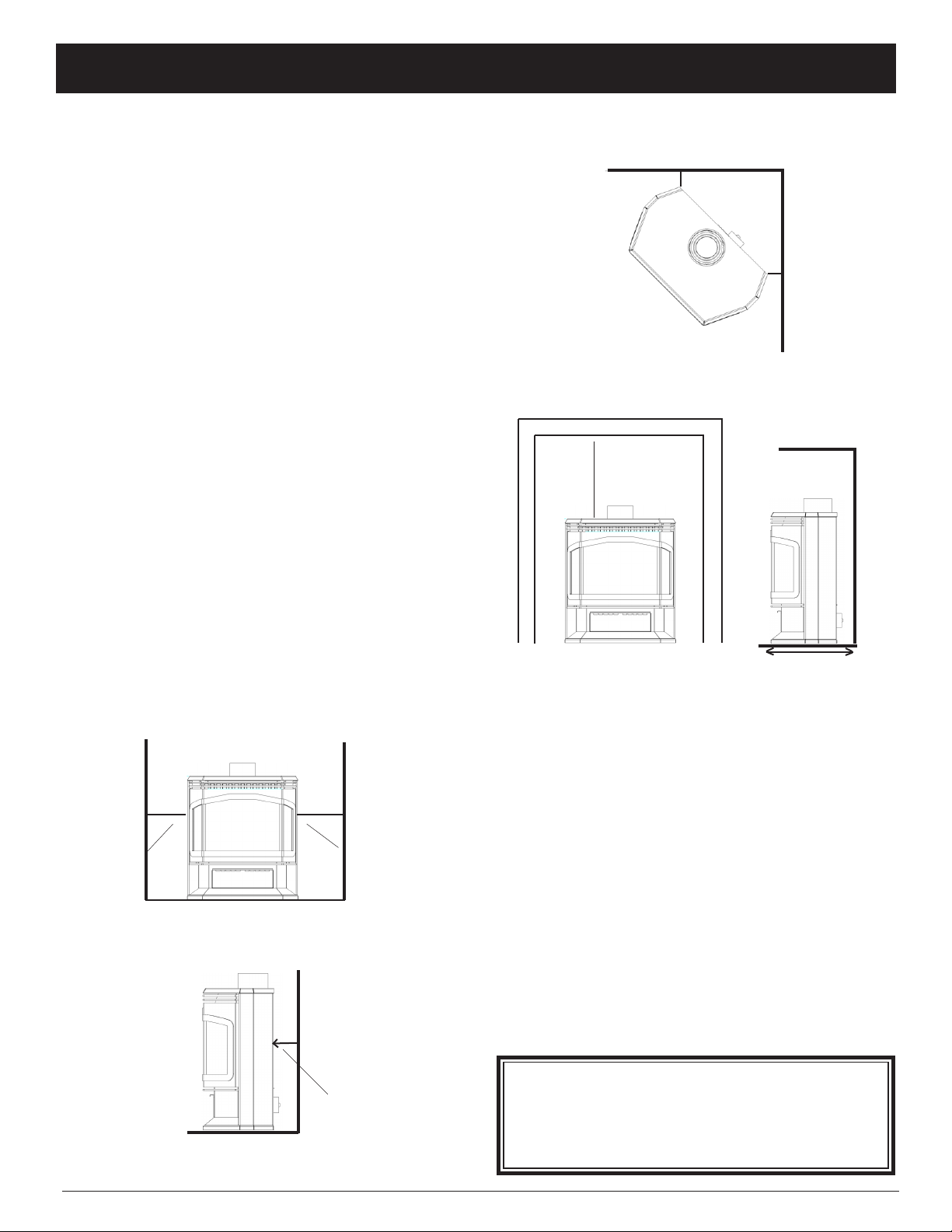
Clearances
The following clearances to combustibles must be
observed:
Heater to left sidewall 9" (230 mm)
Heater to right sidewall 9" (230 mm)
Heater corner to walls 4" (100 mm)
Heater to back wall 3" (75 mm)
(measured from rear of heater to wall)
Heater to alcove ceiling 18" (460 mm)
Maximum alcove depth 14" (355 mm)
In addition to the clearances mentioned previously,
adequate accessibility clearance for servicing and proper
operation must be maintained.
If this appliance is installed directly on carpeting, vinyl
tile, or other combustible material other than wood ooring
the appliance shall be installed on a metal or wood panel extending at least the full width and depth of the appliance.
Clearance from corner of unit to walls.
18" (460 mm)
Clearance to alcove ceiling.
4"
4"
14" (355 mm)
Maximum alcove depth
9" (230 mm) 9" (230 mm)
3" (75 mm)
Clearance to back wall
Air openings into the combustion chamber
must remain clear at all times. Also ensure
adequate accessibility clearances for servicing
and proper operation.
Page 5
VENTING
5
Use Only Approved Venting
The Clarity Direct Vent Gas Heater has been tested and
is listed for installation with specic venting components.
The venting manufacturer's warranty will be voided, and
serious re, health, or other safety hazards may result from
any of the following actions:
• Installation of any damaged venting component.
• Unauthorized modication of the venting System.
• Installation of any venting component not manufactured
by an approved manufacturer.
• Installation other than as instructed by the venting
manufacturer and the appliance manufacturer.
Consult your local building codes before beginning
the installation, and follow the manufacturer's instructions
exactly. The following Simpson Duravent GS 4" X 6 5/8"
venting components are approved for use with the Clarity
Direct Vent Gas Heater.
SIMPSON DURA-VENT COMPONENT NO.
Basic Termination Kit ................................................... 970
Horizontal Termination Kit A ....................................... 971
VerticalTermination Kit A ............................................. 973
Horizontal Square Termination Cap ............................. 984
VerticalTermination Cap ............................................... 983
Snorkel Termination Cap, 36" Vertical Rise ................. 981
Snorkel Termination Cap, 14" Vertical Rise ................. 982
Vinyl Siding Standoff ................................................... 950
Wall Thimble ............................................................... 942
Round Ceiling Support/Wall Thimble Cover ............... 940
Cathedral Ceiling Support Box ..................................... 941
Storm Collar .................................................................. 953
Firestop Spacer ............................................................. 963
Adjustable Roof Flashing, 0/12-6/12 pitch ................... 943
Steep Roof Flashing, 7/12-12/12 pitch ....................... 943S
Wall Strap ..................................................................... 988
Designer Series Trim Kits ..................... 3951, 3952, 3953,
3960, 3961, 3962
High Wind Vertical Termination Cap ........................... 991
Low Prole Termination Cap ....................................... 980
DIRECT VENT PIPE LENGTHS
DURA-VENT COMPONENT NO.
GALVANIZED BLACK
6" length NA 908B
9" length NA 907B
12" length 906 906B
24" length 904 904B
36" length 903 903B
48" length 902 902B
11-14 5/8" Adjustable - 911B
45° Elbow 945 945B
90° Elbow 990 990B
WARNING: The ow of ventilation air must not be
obstructed.
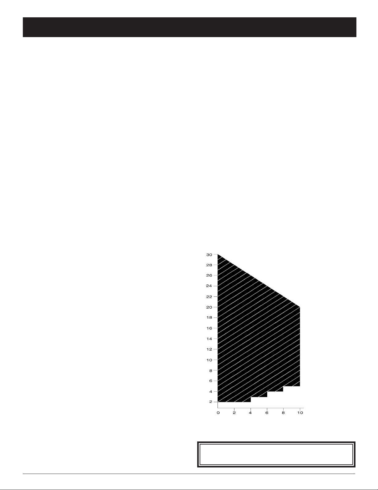
Horizontal and Vertical Venting Requirements
The maximum horizontal run allowed for the Clarity
Direct Vent is 10 feet. The maximum vertical rise and
maximum total vent length is 30 feet. The horizontal and
vertical lengths of venting must fall within the shaded portion of the chart below:
Restrictor plates, supplied by Harman Stove Company,
(Part No. G218) may be added in straight vertical instal-
lations only. For each 10' of vertical rise above the rst
10', one restrictor plate may be added. No more than two
restrictor plates may be used.
For venting systems that utilize one or two elbows (either
45° or 90°), restrictor plates should not be used.
For the Clarity Direct Vent, the vent/air intake termination clearances above the high side of an angled roof are
as follows:
Roof Pitch Feet Meters
Flat to 6/12 1 0.3
7/12 to 9/12 2 0.6
10/12 to 12/12 4 1.2
13/12 to 16/12 6 1.8
17/12 to 21/12 8 2.4
Vertical rise (feet)
Horizontal run (feet)
The Clarity Direct Vent should be installed with no
more than 12 joints and 2 elbows. The elbows may be either
45° or 90°.
The Clarity Direct Vent must not be connected to a chim-
ney ue serving any other appliance.
Venting terminals shall not be recessed
into a wall or siding.
Page 6

6
VENTING
Requirements for Terminating the Venting
WARNING: Venting terminals must not be recessed into a wall or siding.
In addition, the following must be observed:
1
A= Clearance above grade,
veranda, porch, deck, or balcony
B= Clearance to window or door
that may be opened
C= Clearance to permanently
closed window
D= Vertical clearance to ventilated soft
located above the terminal within a
horizontal distance of 2 feet (61 cm)
from the center line of the terminal
E= Clearance to unventillated soft
F= Clearance to outside corner
G= Clearance to inside corner
H= Clearance to each side of
center line extended above
meter/regulator assembly
I= Clearance to service regulator
vent outlet
J= Clearance to nonmechanical
air supply inlet to building or
the combustion air inlet to any
other appliance
K= Clearance to a mechanical air
supply inlet
L= Clearance above paved sidewalk
or paved driveway located on
public property
M= Clearance under veranda, porch
deck, or balcony
Canadian Installations
12 Inches (30 cm)
6 Inches (15 cm) for appliance < 10,000
Btuh (3 kW), 12 inches (30 cm) for
appliances > 10,000 Btuh (3kW) and <
100,000 Btuh (30 kW), 36 inches (91 cm)
for aplliances > 100,000 Btuh (30 kW)
*
*
*
*
*
3 feet (91 cm) within a height of 15
feet above the meter/ regulator assembly
6 feet (1.83 m)
6 inches (15 cm) for appliances < 10,000
Btuh (3 kW), 12 inches (30 cm) for
appliances > 10,000 Btuh (3 kW) and <
100,000 Btuh (30 kW), 36 inches (91 cm)
for appliances > 100,000 Btuh (30 kW)
6 feet (1.83 m)
7 feet (2.13 m) †
12 inches (30 cm) ‡
US Installations
2
12 inches (30 cm)
6 Inches (15 cm) for appliance < 10,000
Btuh (3 kW), 9 inches (23 cm) for
appliances > 10,000 Btuh (3kW) and <
50,000 Btuh (15 kW), 12 inches (30 cm)
for aplliances > 50,000 Btuh (15 kW)
*
*
*
*
*
*
*
6 Inches (15 cm) for appliance < 10,000
Btuh (3 kW), 9 inches (23 cm) for
appliances > 10,000 Btuh (3kW) and <
50,000 Btuh (15 kW), 12 inches (30 cm)
for aplliances > 50,000 Btuh (15 kW)
3 feet (91 cm) above if within 10 feet
(3 m) horizontally
*
*
1
In accordance with the current CSA-B149. 1 Natural Gas and Propane Installation Code
2
In accordance with the current ANSI Z223.1 / NFPA 54 National Fuel Gas Code
† A vent shall not terminate directly above a sidewalk or paved driveway that is located between two single family dwellings and
serves
both dwellings.
‡ Permitted only if veranda, porch, deck, or balcony is fully open on a minimum of two sides beneath the oor.
* For clearances not specied in ANSI Z223. 1 / NFPA 54 or CSA-B149.1, one of the following shall be indicated:
a) A minimum clearance value determined by testing in accordance with section 2.19.6, or;
b) A reference to the following footnote:
“Clearance in accordance with local installation codes and the requirements of the gas supplier”
«Dégagement conforme aux codes d’installation locaux et aux exigences du foumisseunde gaz»
Page 7
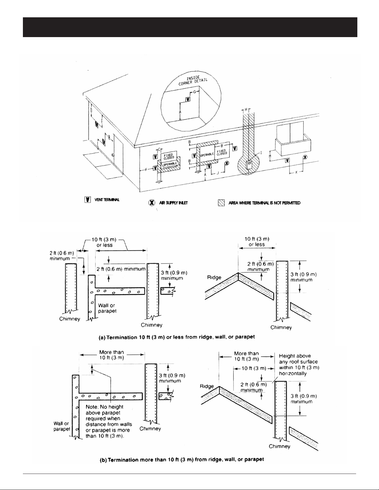
VENTING
These Diagrams, along with the table, detail the restrictions on the vent terminal location.
7
Vent cap regulations:
Page 8

8
Use Only Approved Venting
This appliance has been tested and is listed for installation only with specic venting components. The
venting manufacturer's warranty will be voided, and serious re, health, or other safety hazards may result
from any of the following actions:
• Installation of any damaged venting component.
• Unauthorized modication of the venting system.
• Installation of any venting component part not manufactured by the approved manufacturer.
• Installation other than as instructed by the venting manufacturer and the appliance manufacturer.
Consult your local building codes before beginning the installation, and follow the manufacturer's
instructions exactly. The Simpson Duravent GS venting components listed below are approved for use with
the Clarity Direct Vent Gas Heater.
Part Numbers for SimpsonDura-Vent Pipe and Fittings
6-5/8" x 4" 8” x 5” Description
n/a 1208 6” Pipe Length
908B 1208B 6” Pipe Length, Black
n/a 1207 9” Pipe Length
907B 1207B 9” Pipe Length, Black
906 1206 12” Pipe Length
906B 1206B 12” Pipe Length, Black
904 1204 24” Pipe Length
904B 1204B 24” Pipe Length, Black
903 1203 36” Pipe Length
903B 1203B 36” Pipe Length, Black
902 1202 48” Pipe Length
902B 1202B 48” Pipe Length, Black
n/a 1211 11” to 14-5/8” Pipe, Adjustable
911B 1211B 11” to 14-5/8” Pipe, Adjustable, Black
n/a 1217 17” to 24” Pipe, Adjustable
945 1245 45o Elbow
945B 1245B 34o Elbow, Black
990 1290 90o Elbow
990B 1290B 90o Elbow, Black
940 1240 Rnd Support Box/Wall Thimble Cover
941 1241 Cathedral Ceiling Support Box
943 1243 Flashing, 0/12 to 6/12 Roof Pitch
943S 1243S Flashing, 7/12 to 12/12 Roof Pitch
953 1253 Storm Collar
963 1263 Ceiling Firestop
988 1288 Wall Strap
981 1281 Snorkel Termination (36”)
982 1282 Snorkel Termination (14”)
984 1284 Horizontal Square Termination
980 1280 Vertical Termination
991 1291 Vertical Termination, High Wind
950 1250 Vinyl Siding Standoff
1222D (Only available from Harman) 8” x 5” to 6 5/8” x 4” Adaptor
VENTING
Page 9

VENTING
Simpson Dura-Vent Direct Vent GS
9
Selkirk Direct-Temp
Stock No. Description
4DT-6 6” Pipe Length, Galvanized
4DT-6B 6” Pipe Length, Black
4DT-9 9” Pipe Length, Galvanized
4DT-9B 9” Pipe Length, Black
4DT-12 12” Pipe Length, Galvanized
4DT-12B 12” Pipe Length, Black
4DT-18 18” Pipe Length, Galvanized
4DT-18B 18” Pipe Length, Black
4DT-24 24” Pipe Length, Galvanized
4DT-24B 24” Pipe Length, Black
4DT-36 36” Pipe Length, Galvanized
4DT-36B 36” Pipe Length, Black
4DT-48 48” Pipe Length, Galvanized
4DT-48B 48” Pipe Length, Black
4DT-AJ Adjustable Length, 11” - 14”, Galv.
4DT-AJB Adjustable Length, 11” - 14”, Black
4DT-EL45 45o Elbow, Galvanized
4DT-EL45B 45o Elbow, Black
4DT-EL90 90o Elbow, Galvanized
4DT-EL90B 90o Elbow, Black
4DT-AA Appliance Adaptor, Black
4DT-RD Restriction Disc
4DT-CS Ceiling Support
4DT-CSS Cathedral Support Box
4DT-WS/B Wall Support Band
4DT-OS Offset Support
4DT-WT Round Wall Thimble, Black
4DT-FS Firestop Spacer
4DT-TP Trim Plate, Black
4DT-HKA Horizontal Term. Kit A
4DT-HKB Horizontal Term. Kit B
4DT-VKC Vertical Termination Kit
4DT-HVC High Wind Vertical Cap
4DT-HHC High Wind Horizontal Cap
4DT-SC Storm Collar
4DT-AF6 Adjustable Flashing, 0/12-6/12
4DT-AF12 Adjustable Flashing 6/12-12/12
4DT-VS Vinyl Siding Standoff
4DT-VSP Vinyl Siding Shield Plate
4DT-ST14 Snorkel Termination 14”
4DT-ST36 Snorkel Termination 36”
Simpson Dura-Vent Direct Vent GS
Stock No. Description
908 6” Pipe Length, Galvanized
908B 6” Pipe Length, Black
907 9” Pipe Length, Galvanized
907B 9” Pipe Length, Black
906 12” Pipe Length, Galvanized
906B 12” Pipe Length, Black
n/a
n/a
904 24” Pipe Length, Galvanized
904B 24” Pipe Length, Black
903 36” Pipe Length, Galvanized
903B 36” Pipe Length, Black
902 48” Pipe Length, Galvanized
902B 48” Pipe Length, Black
911 Adjustable Length, 11”-14”, Galv.
911B Adjustable Length, 11”-14”, Black
945 45o Elbow, Galvanized
945B 45o Elbow, Black
990 90o Elbow, Galvanized
90B 90o Elbow, Black
n/a
929 Restrictor Disc
949 Round Ceiling Spt/Wall Thimble Cvr
941 Cathedral Ceiling Support Box
988 Wall Strap
989 Elbow Strap
942 Wall Thimble
963 Ceiling Firestop
n/a
970 Basic Horizontal Term. Kit
971 Horizontal Termination Kit A
978 Vertical Termination Kit
991 High Wind Termination Cap
985 Horizontal Square High Wind Termination
953 Storm Collar
943 Adjustable Flashing, 0/12-6/12
943S Adjustable Flashing 6/12-12/12
950 Vinyl Siding Standoff
n/a
982 Snorkel Termination Cap 14”
981 Snorkel Termination Cap 36”
Page 10

10
VENTING
SECURE VENT DIRECT VENT SYSTEM - 4” x 6-5/8” and 5” x 8” Cross Reference List
Secure
Description
Length 6” (Galvalume).........................SV4L6 908 SV5L6 1208
Length 6” (Black)................................SV4LB6 908B SV5LB6 1208B
Length 12” (Galvalume).......................SV4L12 906 SV5L12 1206
Length 12” (Black)..............................SV4LB12 906B SV5LB12 1206B
Length 24” (Galvalume).......................SV4L24 904 SV5L24 1204
Length 24” (Black)..............................SV4LB24 904B SV5LB24 1204B
Length 36” (Galvalume).......................SV4L36 903 SV5L36 1203
Length 36” (Black)..............................SV4LB36 903B SV5LB36 1203B
Length 48” (Galvalume).......................SV4L48 902 SV5L48 1202
Length 48” (Black)..............................SV4LB48 902B SV5LB48 1202B
Adj. Length (Galv.)(Adjustable 6”).........SV4LA n/a SV5LA n/a
Adj. Length (Blk)(Adjustable 6”)...........SV4LBA n/a SV5LBA n/a
Adj. Length (Galv.)(Adjustable 12”).......SV4LA12 n/a SV5LA12 n/a
Adj. Length (Blk)(Adjustable 12”).........SV4LBA12 n/a SV5LBA12 n/a
Adj. Length (Galv.)(Adjustable 24”).......SV4LA24 917 SV5LA24 1217
Adj. Length (Blk)(Adjustable 24”)..........SV4LBA24 917B SV5LBA24 1217B
Swivel 45o elbow (Galvalume)...............SV4E45 945G SV5E45 1245G
Swivel 45o elbow (Black).....................SV4EB45 945BG SV5EB45 1245BG
Rigid 45o elbow (Black).......................SV4EBR45 945B SV5EBR45 1245B
Swivel 90o elbow (Galvalume)..............SV4E90 990G SV5E90 1290G
Swivel 90o elbow (Black).....................SV4EB90 990BG SV5EB90 1290BG
Rigid 90o elbow (Black).......................SV4EBR90 990B SV5EBR90 1290B
Vent
Cat No.
Simpson Dura-Vent
Direct Vent GS
Stock No.
Secure
Vent
Cat No.
Simpson Dura-Vent
Direct Vent GS
Stock No.
Adjustable Decorative
Square Cathedral Support...................SV4CSB 941 SV5CSB 1241
Collar for the Decorative
Square Cathedral Support....................SV4AC n/a SV5AC n/a
Decorative Black Plate (square)...........SV4PF 940 SV5PF 1240
Universal Support...............................SV4SU 989 SV5SU 1289
Floor Support.....................................SV4SD n/a SV5SD n/a
Roof Brace.........................................SV4BS n/a SV5BS n/a
Roof Support......................................SV4ST n/a SV5ST n/a
Wall Band..........................................SV4BM 988 SV5BM 1288
Attic Radiation Shield..........................SV4RSA n/a SV5RSA n/a
Wall Radiation Shield..........................SV4RSM 942 SV5RSM 1242
Firestop..............................................SV4BF 963 SV5BF 1263
Flat Roof Flashing(storm collar incl.)....SV4F 943F SV5F 1243F
Adjustable Roof Flashing
1/12 - 7/12 (storm collar incl.)..............SV4FA 943 SV5FA 1243
Adjustable Roof Flashing
8/12 - 12/12 (storm collar incl.)............SV4FB 943S SV5F B 1243S
Storm Collar.......................................SV4FC 953 SV5FC 1253
Vinyl Shield Protector.........................SV4VS 950 SV5VS 1250
Restrictor Disk...................................SV4RD 929 SV5RD n/a
VERTICAL TERMINATION CAP...........SV4CGV 980 SV5CGV 1280
HORIZONTAL TERMINATION CAP.......SV4CHC-1 984 SV5CHC-1 1284
SNORKEL CAP 14”...........................SV4STC14 982 SV5STC14 1282
SNORKEL CAP 36”...........................SV4STC36 981 SV5STC36 1281
Page 11

VENTING
Montigo Direct Vent
Standard Series Direct Vent (4"/ 7")
Description Order Code
HORIZONTAL TERMINATIONS
3" length, no mounting frame (use with MSR or MOSR) .................... MTO3
3" Termination, with integral mounting frame .................................... MTO3F
VERTICAL TERMINATION
Termination for vertical installations ..................................................MVTK1
Includes MXT-10 adaptor (for straight, vertical installations)
Termination Touch-Up Paint ............................................................Paint03
11
VENT PIPES
Extensions
18" rigid section (female/female) ..................................................... EXT18
12" rigid section (female/male) ........................................................MEXT1
24" rigid section (female/male) ........................................................MEXT2
36" rigid section (female/male) ........................................................MEXT3
48" rigid section (female/male) ........................................................MEXT4
72" rigid section (female/male) ........................................................MEXT6
Flex Sections
12" ex section (female/female connectors) .....................................MFL1
18" ex section (female/female) ......................................................MFL18
24" ex section (female/female) ..................................................... MFL2
36" ex section (female/female) ......................................................MFL3
48" ex section (female/female) ......................................................MFL4
Elbows
45° solid elbow section.(female/male connectors) .............................EEL45
90° elbow (female/female) ..............................................................MEL90F/F
90° elbow (male/male). ..................................................................MEL90M/M
90° elbow (female/male). ...............................................................MEL90F/M
Clearance Reducing Sleeve ............................................................CRS30
Vertical Installation Adaptor
10" ue adaptor for straight, vertical installations (female/female) ........ MXT10
Vent Connector
4" vent connector (male/male) ........................................................ MVA
TERMINATION FRAMES
Siding or Stucco Frame ..............................................................MSR
Used for easy installation of termination.
Siding or Stucco Can ..................................................................MOSR
Used to provide installation of termination from the inside of the building.
Brick Siding Can
Used for installation of termination on brick wall.
4" depth ........................................................................................BSR-4
6" depth ........................................................................................BSR-6
Page 12

12
VENTING
Montigo Direct Vent
Standard Series Direct Vent (4"/ 7")
Description Order Code
SNORKEL TERMINATIONS
18" vertical rise .............................................................................. SNK47-2
30" vertical rise ...............................................................................SNK47-3
HEAT GUARD
Fits all Standard Series (4/7") terminations ........................................MTKOG
HEAT SHIELDS
Through-the-wall Radiation Shield for 4"/7" venting .......................RHS100
Vinyl Siding Shield Recommended for protecting vinyl siding ........... RHS105
(above was Discontinued Replace with VSS)
Vinyl Siding Shield Recommended for protecting vinyl siding ............VSS
VERTICAL INSTALLATION ACCESSORIES
7" Firestop .....................................................................................FS7
7" Support plate & support ring ........................................................MSPXT7
7" Support plate & support ring (Bulk pack of 6) ................................MSP706
Flashing and storm collar for 1/12 to 7/12 pitch roof .......................... MRF7
Flashing and storm collar for 1/12 to 7/12 pitch roof (Bulk pack of 6) ....MRF706
Flashing and storm collar for 7/12 to 12/12 pitch roof ..........................MRF-12
Flashing and storm collar for 7/12 to 12/12 pitch roof (Bulk pack of 6) ..MRF1206
Horizontal Vent Restrictors
For 8' - 14' horizontal vent run ...........................................................MHVR8
For 15' - 24" horizontal vent run ........................................................MHVR15
For 25' - 35' horitontal vent run ......................................................... MHVR25
Vent restrictors may not be required. Contact the factory for more information.
Vertical Vent Restrictors
For 8' - 14' vertical vent run ...............................................................MVVR8
For 15' - 24" vertical vent run .............................................................MVVR15
For 25' or greater vertical vent run ......................................................MVVR25
Vent restrictors may not be required. Contact the factory for more information.
MOBILE HOME KITS
Wall Penetration Kit (For 2 x 4 Construction) ....................................WPKMH4
Kit includes wall shield and 4" termination. Suitable for all
corner installations & straight through the wall installations
with 2 x 4 construction.
Wall Penetration Kit (For 2 x 6 Construction) ....................................WPKMH6
Kit includes wall shield and 5" termination.
Page 13

VENTING
Montigo Direct Vent
Premium Series Direct Vent (5"/8")
Description Order Code
HORIZONTAL TERMINATIONS
3" Termination with no mounting frame (male connector). ..................... PTO3
(use with MSR or MOSR).
3" Termination & mounting frame (male connector). ............................. PTO3F
VERTICAL TERMINATION
Termination for vertical installations (male connector) ........................... PVTK1
Includes PXT-10 adaptor (for straight, vertical installations).
VENT PIPES
Note: For all Rear Vent applications with no vertical rise, there is a maximum horizontal run
of 20".
Extensions
5" rigid section (female/female connectors) .......................................... PXT5
10" rigid section (female/female) ......................................................... PXT10 .
20" rigid section (female/female) ......................................................... PXT20
12" rigid section (female/male connectors) .......................................... PEXT1
24" rigid section (female/male) ........................................................... PEXT2
36" rigid section (female/male)............................................................ PEXT3
48" rigid section (female/mal............................................................... PEXT4
72" rigid section (female/male) ........................................................... PEXT6
Flex Sections
12" ex section (female/female connectors) ........................................ PFL1
18" ex section (female/female........................................................... PFL18
24" ex section (female/female) ......................................................... PFL2
36" ex section (female/female) ......................................................... PFL3
48" ex section (female/female) ......................................................... PFL4
Elbows
45° elbow (female/male connectors) .................................................. PEL45FM
90° elbow (female/female connectors) ................................................PEL90F/F
90° elbow (male/male) ......................................................................PEL90M/M
90° elbow (female/male) ...................................................................PEL90F/M
Clearance Reducing Sleeve ...............................................................CRS30
Vent Connector
4" length vent connector (male/male connectors) ................................. PVA
Vertical Vent Reducer
10" length, reduces vertical 5"/8" venting to 4"/7" (male/female connectors) PVA5487
13
TERMINATION FRAMES
Siding or Stucco Frame ..................................................................MSR
Used for easy installation of termination.
Siding or Stucco Can ......................................................................MOSR
Used to provide installation of termination from the inside of the building.
Brick Siding Can
Used for installation of termination on brick wall.
4" depth ............................................................................................ BSR-4
6" depth .............................................................................................BSR-6
Page 14

14
VENTING
Montigo Direct Vent
Premium Series Direct Vent (5"/8")
Description Order Code
SNORKEL TERMINATIONS
18" vertical rise ......................................................................................SNK58-2
30" vertical rise ......................................................................................SNK58-3
INSULATED OFFSET BOX
M38DV-ST offset box. Used only on the M38DV-ST when a shelf or
T.V. stand is required above the replace. ................................................ DVSTCNT
HEAT GUARD
Fits all Premium Series (5"/8" dia.) terminations .......................................PTKOG
HEAT SHIELDS
Through-the-wall Radiation Shield for 5"/8" venting ...............................RHS101
Vinyl Siding Shield Recommended for protecting vinyl siding ...................RHS105 Discontinued
Replace with VSS
Vinyl Siding Shield Recommended for protecting vinyl siding .................. VSS
VERTICAL INSTALLATION ACCESSORIES
8" Firestop ............................................................................................PS8
8" Support plate & support ring ................................................................PSPXT-8
8" Support plate & support ring (Bulk pack of 6) ........................................PSP806
Flashing and storm collar for 1/12 to 7/12 pitch roof ..................................PRF7
Flashing and storm collar for 1/12 to 7/12 pitch roof (Bulk pack of 6) ...........PRF706
Flashing and storm collar for 7/12 to 12/12 pitch roof .................................PRF12
Flashing and storm collar for 7/12 to 12/12 pitch roof (Bulk pack of 6) .........PRF1206
Horizontal Vent Restrictors
For 8' - 14' horizontal vent run ................................................................. PHVR8
For 15' - 24" horizontal vent run ...............................................................PHVR15
For 25' - 35' horitontal vent run .................................................................PHVR25
Vent restrictors may not be required. Contact the factory for more information.
Vertical Vent Restrictors
For 8' - 14' vertical vent run ......................................................................PVVR8
For 15' - 24" vertical vent run ....................................................................PVVR15
For 25' or greater vertical vent run .............................................................PVVR25
Vent restrictors may not be required. Contact the factory for more information.
Page 15

ASSEMBLY
15
Connecting To An Existing Chimney
The Clarity may be connected to an existing masonry
chimney by using a Simpson Dura-Vent conversion kit
#934.
With this kit and a 4" ex liner in the chimney, the ue
gases exit through the 4" liner, and the outside air comes
down the chimney, in the space between the chimney and
the liner. This method allows you to install the Clarity using
your chimney and still get the added efciency provided by
direct venting.
The use of an existing chimney as an air intake is
not covered under the ANSI Z21.88b-2003. CSA 2.33b2003 test methods and the resulting ITS/WHI product
certcation: The code Authority Having Jurisdiction
must be consulted prior to proceeding.
The Clarity is shipped from the factory with the log set
packed inside the rebox. To prepare the stove for installation; The log set must be unpacked. The appropriate fuel
conversion for natural gas, if desired, installed. Install the
logs as instructed.
Removing the Glass Front
NOTE: The glass front is heavy. Be prepared for its
weight when lifting it to avoid damage during removal.
The wing doors on each side are held closed by magnets.
Push on each door to open it. Loosen the wing nut on each
of the two spring-loaded levers. Grasp each lever and push
to the rear to disengage the front. To keep the levers in the
disengaged position, tighten the wing nuts. Lift the glass
front slightly and remove it from the stove. Set the glass
aside in a safe place where it will not be damaged.
The front is released
when spri ng-l oaded
levers on the left and
right sides are pushed
to the rear
Remove and Unwrap the Log Set
As shown in the photo below, the log set consists of a
back log (1), a center log that has a pilot-viewing port in
the left end (2), two ember strips (3), and a branch that rests
on top (4).
In addition, there are two side brick panels and a back
brick panel.
The log set components are shipped from the factory
individually wrapped and packed inside the stove. Take
them out of the stove, then carefully remove the wrapping.
Handle the logs gently to prevent damage.
1
2
4
3
Install the Back Log and Back Brick Panel
These two components are installed as a single piece.
Rest the back brick panel on the shelf located on the back
side of the back log, and center it. Holding the two pieces
as a single unit, tilt the top forward slightly and manuever
it over the top of the rear burner—taking care that the top
corners clear the front opening. Place it snugly against the
back wall and center it.
Install the Side Brick Panels
3
WARNING: Do not abuse the Clarity's glass by
striking, slamming, or similar trauma. Do not operate the Clarity Gas Heater with the glass panel
removed, cracked or broken. Use only glass supplied
by Harman and approved for use with this heater.
Do not use substitute materials. Replacement of
the panel should be done by a licensed or qualied
service person.
These slide into place along each side and are held by
friction. The notch in each panel faces the back. Install one
side, and then the other.
Install the Ember Strips
The ember strips rest against the front of the rebox and
should t snugly. Guide them toward you and to the outside
until they t snugly. Check the air slot in the inside of the
ember strips to conrm that they do not obstruct it.
Optional Ember Screen
There is an optional ember kit available which replaces
the two-piece ember strips with a screen for over the front
burner and some rock-wool and nuggets to give a more
realistic re appearance. If choosing this option, install it
now.
Page 16

16
ASSEMBLY
Install the Center Log
The center log goes all the way to the back and should
be centered. When properly positioned, there should be an
even gap along the front of the center burner in the cavity
in the log. A small portion of the log support frame will be
revealed.
The center log has a round viewing port in the left end
through which the pilot can be observed.
Install the Branch
Orient the branch with the forked end toward the left rear
of the stove and slip it over the two locator pins, one on top
of the back log and the other on the top of the center log.
Secure the Glass Front
NOTE: The glass front is heavy. Lift it carefully to prevent damage. Center the glass on the opening and suspend
it in place by placing the the tab hooks over the top edge
of the opening. Loosen the wing nuts that hold the springloaded levers in place. Press the glass slightly against the
stove to conrm that it seats properly, then press it rmly
against the front while pulling the levers forward to engage
them. Tighten the wing nuts.
The complete log set with all logs in the correct position.
Any safety screen or guard removed for servicing an
appliance must be replaced prior to operating the appliance.
Page 17

CONNECTING THE HEATER TO A GAS SUPPLY
NATURAL GAS
PROPANE
Burn Only the Fuel for which the Heater is Equipped
17
The Clarity Direct Vent is built for use with Propane
but can be converted to burn Natural Gas.The label on the
burner system module indicates the fuel for which it is
equipped, and must be marked upon installation of the stove
or conversion kit. A second label, located near the rating
plate, also indicates the fuel type.
For fuel conversion information, see APPENDIX A
(page 28)
Making The Connection
The gas inlet is located at
the bottom right rear of the
stove. The inlet tting is a 1/2"
female are exible pipe.
A separate gas shut-off valve
and a 1/8" N.P.T. plugged
tapping should be installed
immediately upstream of the
connection to the appliance.
The Clarity Direct Vent Gas Heater must be disconnected from the gas supply piping during any pressure
testing of that system at pressures in excess of 1/2 psig
(3.5 kPa).
The Clarity gas control valve must be in the OFF position during any pressure testing of the gas supply system at
pressures equal to or less than 1/2 psig (3.5 kPa).
WARNING: To avoid pipe compounds from enter-
ing into the gas train, apply compounds only to male
pipe threads and do not apply compound to the rst
two threads.
WARNING: This product must be installed by a li-
censed plumber or gas tter when installed within the
Commonwealth of Massachusetts.
Natural Gas:
Maximum inlet pressure 7.0" w.c. (1.74 kPa)
Minimum inlet pressure 5.0" w.c. (1.25 kPa)
Gas manifold pressure 3.5" w.c. (0.87 kPa)
LPG Gas:
Maximum inlet pressure 13" w.c. (3.24 kPa)
Minimum inlet pressure 11" w.c. (2.74 kPa)
Gas manifold pressure 10" w.c. (2.49 kPa)
RECOMMENDED GAS PIPE DIAMETER
Pipe Length Schedule 40 Pipe Tubing, Type L
(Feet) Inside Diameter Outside Diameter
N.G. L.P. N.G. L.P.
0-10 1/2” 3/8” 1/2” 3/8”
1.3 cm 1.0 cm 1.3 cm 1.0 cm
10-40 1/2” 1/2” 5/8” 1/2”
1.3 cm 1.3 cm 1.6 cm 1.3 cm
40-100 1/2” 1/2” 3/4” 1/2”
1.3 cm 1.3 cm 1.6 cm 1.3 cm
100-150 3/4” 1/2” 7/8” 3/4”
2.0 cm 1.3 cm 2.3 cm 2.0 cm
NOTE: NEVER USE PLASTIC PIPE. CHECK TO CONFIRM
WHETHER YOUR LOCAL CODES ALLOW COPPER
TUBING OR GALVANIZED PIPE.
Installer Fuel Label Shown below. Note that when
converting to Natural Gas, the appropriate label must be
installed.
CAUTION: TEST ALL JOINTS FOR LEAKS BE-
FORE OPERATING
Gas Pressure Requirements
Correct gas pressure and the use of a properly sized
gas supply line are essential for the safe and efcient per-
formance of this appliance. Make sure that the plumber or
gas supplier checks the gas supply line and gas pressure at
installation.
NOTE: Improper gas pressure can affect heater perfor-
mance, ame color, or cause pilot outage.
Page 18

18
CONNECTING THE HEATER TO CORDSET
Connecting the Cordset
The Clarity Direct Vent Gas Heater must be installed
in accordance with local codes or, in the absence of local
codes, with the most recent edition of the National Electrical Code ANSI/NFPA 70, or the current Canadian Electrical
Code C22.1.
NOTE: The convection fan requires a 120 VAC supply
for operation, but the heater can be operated without the fan
as in the case of a power outage.
Plug the 3-prong grounded electrical cord plug into
the wall.
WARNING: This heater is equipped with a threepronged grounding plug that should be plugged
directly into a properly grounded receptacle. Do not
cut or remove the grounding prong from the plug.
Connecting the Optional Thermostat
If the optional thermostat is used, it must be plugged
into the terminal strip located in the left rear corner of the
heater.
When installing a millivolt control system, use only
a special low resistance thermostat. Do not use a regular
heating thermostat.
Terminal strip
location
Rear view of Clarity
Be sure that all electrical connections are clean, free
from corrosion, and tight. Inspect connections periodically
to conrm that no corrosion has built up over time.
When properly installed and maintained, a millivolt
control system should give many years of trouble-free
service.
It is important to use wire of a gauge proper for the
length of the wire:
RECOMMENDED WIRE GAUGES
Maximum Wire
Length Gauge
100' 14
60' 16
40' 18
25' 20
15' 22
Page 19

AIR SHUTTER ADJUSTMENT
AIR SHUTTER ADJUSTMENT
19
The nal step of the installation is to check the ame
pattern, which should resemble the pattern illustrated in the
right column: The ames should be relatively well-dened
and stable. They should be bright yellow with a blue base
where attached to the burner ports, and should not look
orange or sooty.
Start the heater according to the directions, and allow the
heater to burn for approximately 15 minutes. The ames
will increase in length and become more yellow in color as
the Clarity heats up.
If the ames do not resemble the description above and
the illustration in the right column, the air shutters may
need to be adjusted.
Three separate screws—one for each burner—are used to
adjust the ames for a particular installation. Two of them
are accessible through the side access port on the right side
of the stove. The third is accessible from the front when
the control door is open. The screws may become hot to
the touch after prolonged operation. Use a glove to avoid
contact if hot. For best results when ne-tuning the ame
picture, initially, leave the middle screw unchanged from
its factory setting. Turn the other two screws as needed to
increase or decrease the brightness and length of the ame:
turning counterclockwise will decrease the ame; turning
clockwise will increase the ame.
1. To adjust the rear burner, open the right wing door,
reach through the side access port, and turn the rear screw
to adjust ame (see directions above).
2. To adjust the front burner, rst open the control door,
then turn the front screw to adjust ame (see directions
above).
Repeat the procedure as needed until the desired ame
effect is achieved.
Monitoring the Gas Flame
Periodically, the ames of the Clarity Direct Vent Gas
Heater should be checked while it is in operation. The
ames should be relatively well-dened and stable. They
should be bright yellow with a blue base where attached
to the burner ports. The ames should not look orange or
sooty. Portions of the logs will glow red when the ames
are properly adjusted.
If you nd the ames to be other than that described here,
do not operate the heater. Consult a qualied service person
or your Harman dealer for advice.
The Clarity ame pattern will resemble this when the unit is
burning properly.
The properly-burning pilot will
resemble the illustration to the
right.
Rear Burner
Center burner
Front burner
Air adjustment screws
Page 20

20
HOW TO LIGHT THE FIRE
OPERATION
1. STOP! Read the safety information on the left side of
the panel on page 21.
2. If using the optional thermostat, set thermostat to the
lowest setting.
3. Turn off electric power to the appliance.
4. Turn the ON-OFF/THERMOSTAT switch to the OFF
position.
5. Push in the gas control knob slightly and turn it clock-
wise to "OFF." NOTE: The knob cannot be turned from
"PILOT" to "OFF" unless it is pushed in slightly. Do not
force it.
6. Wait ve (5) minutes to clear out any gas. If you then
smell gas, STOP! Follow "B" in the safety information on
page 21. If you don't smell gas, go to the next step.
7. Set the High-Low Regulator to High by turning it fully
counterclockwise.
8. Press in the gas control knob slightly and turn coun-
terclockwise to "PILOT."
9. Find the pilot by looking through the round opening
on the left end of the center log.
10. Push the control knob fully down and hold. Immedi-
ately push the red piezo ignitor button to light the pilot. It is
normal to have to push the red button several times before
the pilot ignites. Continue to hold the control knob in for
about one (1) minute after the pilot is lit. Release the knob
and it will pop back up. Pilot should remain lit. If it goes
out, repeat steps 5 through 9.
•If the knob does not pop up when released, stop and
immediately call your service technician or gas supplier.
•If the pilot will not stay lit after several tries, turn the
gas control knob to "OFF" and call your service technician
or gas supplier.
11. Turn the gas control knob counterclockwise to
"ON."
12. Place the ON-OFF/THERMOSTAT switch in the ON
position or in the THERMOSTAT position if the optional
thermostat is used.
13. Turn on the electric power to the heater.
14. Set the optional thermostat to the desired room temperature.
15. Set the High-Low Regulator to desired setting: turn
fully counterclockwise for High and fully clockwise for
Low.
NOTE: An odor resulting from the initial heating of new
materials in your heater is not unusual during the rst re,
and in most cases will disappear after an hour or two.
HOW TO TURN OFF THE FIRE
1. If using optional thermostat, set thermostat to the low-
est position.
2. Turn off the electric power to the appliance.
3. Turn the ON-OFF/THERMOSTAT switch to the OFF
position.
4. Push in the gas control knob slightly and turn it clock-
wise to “OFF.”
NOTE: The knob cannot be turned from “PILOT” to
“OFF” unless it is pushed in slightly. Do not force it.
Page 21

SAFETY/LIGHTING LABEL
21
Page 22

22
MAINTENANCE
A qualied service person recommended by your Harman
dealer should conduct an annual inspection and maintenance
of your Clarity, its venting, and the installation to keep it
running safely and efciently. The following procedures
should be performed only by a qualied service person. The
gas supply should be turned off whenever a maintenance
procedure is performed.
If the glass front, side doors, or front access door are
removed for servicing, they must be replaced prior to operating the Clarity.
Removing the Glass for Replacement
To remove the glass panel in the door, remove upper and
lower glass clips and lift the glass out. Use only authorized
Harman replacement glass components available from your
Harman dealer.
Replacing the Gasket
The Clarity has 5/8" diameter berglass gasket in the front
door. Should it ever need replacement, use only the proper
replacement gasket that is available from your Harman
dealer. To replace the gasket, follow this procedure.
1. Open the door
2. Remove the existing gasket and clean its channel with
a scraper or wire brush.
3. Lay a thin bead of high temperature silicone the entire
length of the channel.
4. Lay the gasket in the channel with sufcient pressure
that is stays in place.
5. Trim the excess from the end of the gasket so that it
butts snugly against the other end without leaving a gap.
Seal the end joint with high temperature silicone.
6. Close the door and apply rm pressure to seat the gasket
evenly throughout.
Cleaning the Glass
The glass may be cleaned with ordinary household glass
cleaner and a soft cloth or paper towel.
WARNING: Never clean the glass when it is hot. Do
not use abrasive cleaners on the glass.
Inspecting the Venting
An inspection of both the inner and outer pipes of the
venting system should be made during the annual service
appointment. They must have no blockage and be in good
repair. The vent manufacturer's instructions may provide
specic suggestions or details on vent inspection. Any sections that are taken apart for the inspection must be reassembled and sealed as required.
Cleaning the Log Set and Firebox
During the annual inspection and maintenance appoint-
ment, the service person should clean dust, lint, and any light
accumulation from the logs and the rebox area. An extra-
soft brush should be used on the logs as they are extremely
fragile; a vacuum cleaner may be used on the rebox. If at
any time the logs cannot be removed or installed without
forcing, the cause must be found. The logs must never be
forced.
Removing the Front
See directions on page 15.
Removal & Re-installation of the Log Set for Cleaning
CAUTION: The ceramic logs are durable when handled
and installed properly. However, they are delicate and may
be damaged easily if not handled with care. Handling damage to the ceramic logs is not covered by warranty.
DO NOT HANDLE LOGS WHILE THEY ARE HOT.
ALLOW PLENTY OF TIME FOR THE STOVE TO COOL
COMPLETELY BEFORE HANLDING.
Remove the Branch
Detach the branch from the two locator pins and remove
it. Brush it gently and carefully place it to one side.
Remove the Center Log
Lift the center log and remove it. Brush it gently and
carefully place it to one side with the branch.
Remove the Ember Strips
Carefully remove the ember strips, clean them, and place
them with the other logs.
Remove the Side Brick Panels
Carefully remove rst one side panel, and then the other.
Clean and place to side.
Remove the Back Log and Back Brick Panel
Finally, carefully remove these two components as a single
piece. Brush them gently and place them to the side.
Finish the procedure by vacuuming the interior of the
rebox, then re-install the logs and secure the glass front
following the procedures on page 15&16.
The appliance area must be kept clear and free from
combustible materials, gasoline and other ammable
vapors and liquids.
Page 23

WIRING DIAGRAM
23
Clarity Direct Vent Wiring Diagram
The Clarity Direct Vent gas heater, when installed, must be electrically grounded in accordance with current
local codes or, in the absence of local codes, with the current edition of National Electrical Code, ANSI/NFPA
70 in the United States or the current Canadian Electrical Code CSA 22.1 in Canada.
WARNING: This heater is equipped with a
three-pronged grounding plug that should be
plugged directly into a properly grounded receptacle. Do not cut or remove the grounding
prong from the plug.
DO NOT USE THIS HEATER IF ANY PART
HAS BEEN UNDER WATER OR EXPOSED TO
MOISTURE CORROSION. IMMEDIATELY CALL A
QUALlFlED SERVICE TECHNICIAN TO INSPECT
THE HEATER AND REPLACE ANY PART OF THE
CONTROL SYSTEM AND ANY GAS CONTROL
WHICH HAS BEEN UNDER WATER.
NE PAS SE SERVIR DE CET APPAREIL S'IL
A ÉTRE PLONGÉ DANS L'EAU, COMPLÉTEMENT OU EN PARTIE. APPELER UN
TECHNICIEN QUALIFIÉ POUR INSPECTER
L'APPAREIL ET REMPLACER TOUTE PARTIE
CAUTION: Label all wires prior to disconnection
when servicing controls. Wiring errors can cause
improper and dangerous operation. Verify proper
labeling after servicing.
«ATTENTION. Au moment de l'entretien des
commandes, étiquetez tous les ls avant de les
débrancher. Des erreurs de câblage peuvent
entraîner un fonctionnement inadéquat et dan-
gereux. S'assurer que l'appareil fonctionne adé-
quatement une fois l'entretien terminé.»
DU SYSTÈME DE CONTRÔLE ET TOUTE
COMMANDE QUI ONT ÉTÉ PLONGÉS DANS
L'LAU.
Page 24

24
PARTS LIST
The following replacement parts for your Harman Clarity Direct Vent are available from your Harman
dealer.
ID#
1.
2.
3.
4.
5.
6.
7.
8.
9.
10.
11.
12.
13.
14.
15.
16.
17.
18.
19.
20.
21.
22.
23.
24.
25.
26.
27.
28.
29.
30.
31.
32.
33.
34.
35.
36.
Part No.
1-89-08250
3-44-08294
3-40-3849239
3-40-08286
3-40-08235
3-40-08236
3-40-08237
3-40-08401
3-40-08232
3-40-08233
3-40-08234
3-40-08693
3-40-08225
3-40-08226
3-31-965487
3-40-00141
3-31-08225
3-20-408412
3-20-326007
3-20-326004
3-20-00907
3-42-2312
3-44-1086405
3-43-4103
3-40-120
3-40-121
3-21-22647
3-44-08287
3-40-820628
3-40-82057
3-40-57356
3-40-64347
3-40-64739
3-40-57271
3-40-57753
3-40-08714
Part
DVG weldment
Starting Collar Gasket
Starting Collar
1/2” gas inlet ex
Rear log
Front log
Top log
Ember strip
Left brick panel
Right brick panel
Rear brick panel
Front burner tube
Center burner tube
Rear burner tube
Ext. spring
Formed wire gold trim
Magnet
Snap disc fan control
21” harness w/terminal block
Power cord
Saftey switch
Glass gasket
5/8” tight knit rope for door
Gold plated door frame
13-3/4” X 19” glass
5-3/4” X 13-3/4” glass
Distribution blower
Pilot tower gasket
NG valve
LP valve
#56 orice, LP front/NG center
#47 orice, NG front
#39 orice, NG rear
#71 orice, LP center
#53 orice, LP rear
Pilot, NG
37.
3-40-08715
38.
3-40-08906
39.
3-40-08220
40.
3-31-08282
41.
3-31-08283
42.
3-31-08234
43.
3-30-310056082
44.
3-20-326006
45.
3-20-326005
46.
3-20-08221
47.
3-20-08219
48.
2-00-08281
49
2-00-4200
50.
2-00-4201
51.
2-00-4172
52.
2-00-4173
53.
1-10-08265-1
54.
1-10-08265-2
55.
2-00-4138-1
56.
2-00-4138-2
57.
1-10-08287
58.
1-10-08258
59.
1-10-08262-1
60.
1-10-08262-2
61.
2-00-4162
62.
2-00-4210
63.
2-00-4177
64.
2-00-4169
Pilot, LP
Thermocouple
Piezo ignitor
90° brass elbow
1/4” tp 3/8” male compression tting
3/8” tp 3/8” male compression tting
BHSCS 5mm X 8mm for valve
18” valve harness
Harness w/VSC
On-Off rocker switch
Thermopile
3/8” tubing
Saftey switch bracket, lower
Saftey switch bracket, upper
Bafe
Snap disc fan control bracket
Latch arm, left
Latch arm, right
Latch cam, left
Latch cam, right
Front door assembly
Top
Left wing door
Right wing door
Control door
Control heat shield
Lower rear access cover
Base trim
Page 25

PARTS
3
58
59
25
17
16
17
55
16
17
57
61
53
51
62
1
49
21
50
18
56
54
60
52
63
27
24
64
Page 26

26
CLARITY BURNER MODULE : EXPLODED VIEW
36
38
47
14
13
12
53
52
33
39
32
31
48
41
42
40
46
Page 27

SPECIFICATIONS
Clarity Direct Vent 929DV Gas Heater
Tested to ANSI Z21.88-2002, CSA 2.33-M02, and CAN/CGA 2.17-M91.
NATURAL GAS PROPANE
Input Rating (Btu/hr) (0-4500 ft) (0-1375 m) 40,000 40,000
Min. Input Rating (Btu/hr) (0-4500 ft) (0-1375 m) 27,000 28,000
Injectors (DMS) (front/middle/rear) (0-4500 ft) (0-1375 m) 45/56/39 56/71/53
Manifold Pressure (in w.c./kPa) 3.5/0.87 10.0/2.49
Minimum Manifold Pressure (in w.c./kPa) 1.7/0.42 5.9/1.47
Minimum Inlet Pressure (in w.c./kPa) 5.0/1.25 11.0/2.74
Maximum Output (Btu/hr) (0-4500 ft) (0-1375 m) 31,200 32,100
AFUE (seasonal efciency; minimum venting) 71.6 % 73.8 %
Steady State Efciency (max. input, blower on High) 80.2 % 83.3 %
MINIMUM CLEARANCES FROM COMBUSTIBLE CONSTRUCTION
27
Unit to left sidewall 9 in. (230 mm)
Unit to right sidewall 9 in. (230 mm)
Unit corner to walls 4 in. (100 mm)
Unit to backwall 3 in. (75 mm)
(measured from rear of stove to wall)
Unit to alcove ceiling 18 in. (460 mm)
Maximum alcove depth 14 in. (460 mm)
Electrical Rating: 120 Volts 60 Hz Less than 1 Amp
Stove weight: 237 lbs.
Page 28

28
NATURAL GAS
PROPANE
APPENDIX A
Converting the Clarity Direct Vent
from One Gas to Another in the Field
NOTE: THE CONVERSION SHALL BE CARRIED OUT IN ACCORDANCE WITH THE REQUIREMENTS OF THE PROVINCIAL OR LOCAL
AUTHORITIES HAVING JURISDICTION AND IN
ACCORDANCE WITH REQUIREMENTS OF THE
CURRENT EDITION OF THE NATIONAL FUEL GAS
CODE, ANSI Z223.1 or the CAN/CGA-B149 INSTALLATION CODES.
Conversion Kit Components
• 2 Burner orices
• 1 Pilot orice
• Regulator Assembly
• Conversion Instructions
• Installer Fuel Label- (shown below)
• Conversion Label- Must be attached to valve upon
completion.
Natural gas conver-
sion Kit, Item #
1-00-08260
Step 3: Using a small at-blade screwdriver, remove
the three screws that hold the LP knob module in place.
Remove the module and replace it with the Natural Gas
module from the kit. See kit instructions.
Step 4: Afx the conversion label to the valve so that any
future service tech etc... can plainly see that the valve was
converted.
Step 5: Mark the appropriate fuel box on the unit label
using a permanent marker.
Step 6: Afx the Installer Fuel Label in place of the exist-
ing one.
Important: Perform a leak test upon completion
of the fuel conversion.
Propane conver-
sion Kit, Item #
1-00-08280
Steps For Completing The Fuel Conversion.
Prior to installing the fuel conversion, remove the Glass
door and the log set, to gain access to the burner module.
Remove the burner tubes by sliding to the left while lifting upward. Remove the burner cover plate and the tube
box top.
Step 1: Remove pilot hood with a 7/16” wrench. Inside,
you will nd and discard the Propane orice. Install the
new Natural Gas orice from the kit. Tighten the pilot
hood and assure proper alignment of the directional openings.
Step 2: Using a 1/2 in. deep-well socket, remove the
three main burner orices. Install the new orices accordingly; Front = #47, Middle = #56, Rear = #39. Notice
the #56 that you removed from the front will be used in
the middle for Natural Gas. Apply a thread sealer to the
orices prior to installing.
The above label on the Clarity's
burner system module indicates
that the unit is equipped to
burn natural gas.
CAUTION: LABEL ALL WIRES PRIOR TO DISCONNECTION WHEN SERVICING CONTROLS. WIRING ERRORS
CAN CAUSE IMPROPER AND DANGEROUS OPERATION.
VERIFY PROPER OPERATION AFTER SERVICING.
The above label on the Clarity's
burner system module indicates
that the unit is equipped to burn
propane.
Page 29

APPENDIX B
29
De-rating for High Altitude
For U.S. installations, the Clarity Direct Vent is approved for elevations up to 2000 feet using the factory-installed burner
injectors. At elevations above 2000 feet, U.S. codes require a decrease in the input rating by changing the burner injectors
to a smaller size. The chart below lists by part numbers the appropriate injectors for both LP and natural gas at various
altitudes.
For Canadian installations, the Clarity Direct Vent is approved for elevations up to 1375 meters (4500 feet). When installing
the Clarity Direct Vent at altitudes above 1375 meters (4500 feet), consult the local gas distributor or the authority having
jurisdiction for proper rating methods.
NOTE: The difference in altitude derating requirements for the U.S. and Canada is simply a result of differences in testing
standards between the two countries.
If the installer must convert the unit to adjust for varying altitudes, an information sticker like the one to the right must be
lled out and afxed to the appliance at the time of conversion.
NATURAL GAS
Front Harman Center Harman Rear Harman Nominal Btu
Altitude Injector Part No. Injector Part No. Injector Part No. Input Rate
0-2000' 47 3-40-64347 56 3-40-57356 39 3-40-64739 40,000
2000-3000' 48 male 56 3-40-57356 40 male 38,400
3000-4000' 49 male 56 3-40-57356 41 male 36,900
4000-5000' 49 male 57 male 42 male 35,400
5000-6000' 50 male 57 male 42 male 34,000
6000-7000' 50 male 57 male 43 male 32,600
7000-8000' 51 male 58 male 43 male 31,300
8000-9000' 51 male 58 male 44 male 30,100
PROPANE
Front Harman Center Harman Rear Harman Nominal Btu
Altitude Injector Part No. Injector Part No. Injector Part No. Input Rate
0-2000' 56 3-40-57356 71 3-40-57271 53 3-40-57753 40,000
2000-3000' 56 3-40-57356 71 3-40-57271 54 male 36,900
3000-4000' 56 3-40-57356 71 3-40-57271 54 male 36,900
4000-5000' 57 male 71 3-40-57271 54 male 35,400
5000-6000' 57 male 71 3-40-57271 55 male 32,600
6000-7000' 57 male 71 3-40-57271 55 male 32,600
7000-8000' 58 male 71 3-40-57271 56 3-40-57356 30,100
8000-9000' 58 male 71 3-40-57271 56 3-40-57356 30,100
* When ordering injectors that have no Harman
part number, specify MALE or FEMALE and the
appropriate 2 digit injector number.
This appliance has been converted for use at an altitude of __________ft.
Orice Sizes: Front ________ Center_________ Rear ________
THE CONVERSION SHALL BE CARRIED OUT
BY A MANUFACTURER'S AUTHORIZED REPRESENTATIVE IN ACCORDANCE WITH THE
REQUIREMENTS OF THE MANUFACTURER,
PROVINCIAL OR TERRITORIAL AUTHORITIES
HAVING JURISDICTION AND IN ACCORDANCE
WITH THE REQUIREMENTS OF THE CURRENT
EDITION OF CAN/CGA-B141.1 OR CAN/CGAB141.2 INSTALLATION CODES.
Input (Btu/hr) _________________
Manifold Pressure __________________
Fuel Type _______________________
Converted By _________________________________
Date of Conversion _______________________________
Page 30

30
Page 31

31
Page 32

 Loading...