

Page 1
Models:
CARODG36I
CARODG36IL
CARODG42I
CARODG42IL
Owner’s Manual
Installation and Operation
CAUTION
DO NOT DISCARD THIS MANUAL
•
• Important operating
and maintenance
instructions included.
Read, understand
and follow these
instructions for safe
installation and
operation.
DANGER
If you smell gas:
1. Shut off gas to the appliance.
2. Extinguish any open fl ame.
3. If odor continues, keep away from the
appliance and immediately call your gas
supplier or fi re department.
WARNING: For Outdoor Use Only.
WARNING
Do not store or use gasoline or other
fl ammable vapors and liquids in the vicinity
of this or any other appliance.
DO NOT
DISCARD
•
Leave this
manual with party
responsible for use
and operation.
WARNING
HOT SURFACES!
Screens and other surfaces are hot
during operation and cool down.
Hot screens will cause burns.
• Do not touch fi replace until it is cooled
• NEVER allow children to touch
fi replace
• Keep children away
• CAREFULLY SUPERVISE children in same area as
fi replace.
• Alert children and adults to hazards of high
temperatures.
High temperatures may ignite clothing or other
fl ammable materials.
• Keep clothing, furniture, draperies and other combustibles
away.
An LP-cylinder not connected for use shall
not be stored in the vicinity of this or any
other appliance.
WARNING! Risk of Fire!
Do not install glass doors on this fi replace.
Glass doors could cause overheating of
adjacent structures.
WARNING: Improper installation,
adjustment, alteration, service or maintenance
can cause injury or property damage. Read
the installation, operating and maintenance
instructions thoroughly before installing or
servicing this equipment.
Outdoor Lifestyles by Hearth & Home Technologies Inc. • Carolina • 4066-300 • Rev. Z • 11/13 1
Installation and service of this appliance should
be performed by qualifi ed personnel. Hearth &
Home Technologies suggests NFI certifi ed or
factory-trained professionals, or
technicians supervised by an NFI
certifi ed professional.
Page 2
Read this manual before installing or operating this appliance.
Please retain this owner’s manual for future reference.
Congratulations
Congratulations on selecting an Outdoor Lifestyles gas appliance—an elegant and clean alternative to wood burning
appliances. The Outdoor Lifestyles gas appliance you have
selected is designed to provide the utmost in safety, reliability, and effi ciency.
As the owner of a new appliance, you’ll want to read and
carefully follow all of the instructions contained in this
owner’s manual. Pay special attention to all cautions and
warnings.
This owner’s manual should be retained for future reference. We suggest you keep it with your other important
documents and product manuals.
The information contained in this owner’s manual, unless
noted otherwise, applies to all models and gas control
systems.
Your new Outdoor Lifestyles gas appliance will give you
years of durable use and trouble-free enjoyment. Welcome
to the Outdoor Lifestyles family of appliance products!
We recommend that you record the following pertinent
Homeowner Reference Information
information about your appliance:
Model Name: Date purchased/installed:
Serial Number: Location on appliance:
Dealership purchased from: Dealer phone:
Notes:
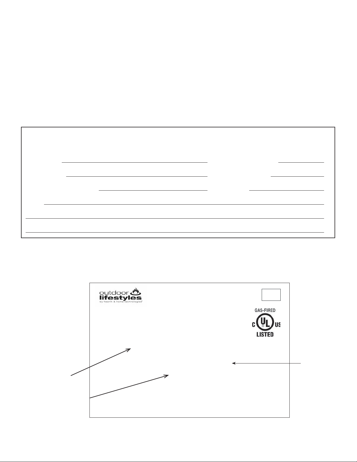
Listing Label Information/Location
The model information regarding your specifi c appliance can be found on the rating plate located on the inside of the
control box cover.
MADE
IN U SA
75 71 21 5th St. W est, Lakeville, MN 5504 4
IAS U.S. 4.96, Outdoor Fireplace
CGA-CR-97-003, Outdoor Fireplace
FOR USE AT HIGH ALTITUDES. This installation must conform with local codes or,
in the absence of local codes, with the National Fuel Gas Code, ANSI Z223.1/NFPA 54,
Model Number
Gas Information
or the Natural Gas and Propane Installation Code, CSA B149.1.
MODEL:
MODÈLE:
Minimum P ermiss ible G as Supply for P urpos es of Input Adjustment:
Approved Mini mum (De Gaz) Acceptable......................XX.X w.c (Po. Col. d’eau)
Maximum Pressure (Pression)...
Min/Max Input BTUH: ............................................XX,XXX/ XX,XXX
Orifice Size:....................................................................#XX / .XXX
Open-flame Gas appliance - for outdoor installation only.
Not for use with solid fuel.
pour installation à l’extérieur seulement. N e doit pas être
utiilsé avec un combustible solide.)
....................................XX.X w.c (Po. Col. d’eau)
(Appareil à gaz à flamme nue –
Propane Gas
29LD
OUTDOOR FIREPLACE
Type of Gas
Outdoor Lifestyles by Hearth & Home Technologies Inc. • Carolina • 4066-300 • Rev. Z • 11/13 2
Page 3

Table of Contents
1 Listing and Code Approvals
A. Appliance Certifi cation 4
B. BTU Specifi cations 4
C. High Altitude Installations 4
D. Non-Combustible Materials Specifi cation 4
E. Combustible Materials Specifi cation 4
F. Electrical Codes 4
G. Fuel 4
2 Getting Started
A. Design and Installation Considerations 5
B. Tools and Supplies Needed 5
C. Inspect Appliance and Components 5
3 Framing and Clearances
A. Select Appliance Location 6
B. Stand-Alone Installation 6
C. Built-in Installation 6
D. Moisture Resistance 6
E. Clearances and Framing Dimensions 7
4 Appliance Preparation
A. Securing and Leveling Appliance 10
B. Flashing 10
5 Gas Information
A. Fuel Conversion 11
B. Gas Pressure 11
C. Gas Connection 11
D. Electrical Codes 12
E. Valve Access 12
F. High Altitude Installations 12
6 Electrical Information
A. IntelliFire Plus™ Pilot Ignition System Wiring 13
B. Control Module Operation 14
C. Installing the Optional Electric Kit 15
7 Finishing
A. Mantel Projections 18
B. Facing Material 18
8 Appliance Setup
A. Clean the Appliance 19
B. Optional Accessories 19
C. Pilot Shield 19
D. Install Lava Rock 19
E. Positioning the Logs 19
F. Place Remaining Lava Rock 22
G. Install Firescreen 23
9 Operating Instructions
A. Gas Fireplace Safety 24
B. Your Fireplace 24
C. Screens 24
D. Before Lighting Fireplace 24
E. Lighting the Appliance 25
F. After the Appliance is Lit 26
10 Troubleshooting
A. IntelliFire Plus™ Ignition System 27
11 Maintaining and Servicing the Appliance
A. Maintenance and Service Tasks 30
12 Reference Materials
A. Appliance Dimension Diagram 31
B. Service Parts List 33
C. Warranty 38
D. Contact Information 40
Note: An arrow () found in the
text signifi es change in content.
Outdoor Lifestyles by Hearth & Home Technologies Inc. • Carolina • 4066-300 • Rev. Z • 11/13 3
Page 4
1
Listing and Code Approvals
1
A. Appliance Certifi cation
MODELS: CARODG36I, CARODG36IL,
CARODG42I, CARODG42IL
LABORATORY: Underwriters Laboratories, Inc. (UL)
TYPE: Outdoor Open-Flame Decorative Gas Appliances
STANDARD: ANSI Z21.97-2008
This product is listed to ANSI standards for “Outdoor OpenFlame Decorative Gas Appliances” and “Gas Fired Appliances for Use at High Altitudes”.
Note: This installation must conform with local codes. In the
absence of local codes you must comply with the National
Fuel Gas Code, ANSI Z223.1-latest edition in the U.S.A.
and the CAN/CGA B149 Installation Codes in Canada.
Note: This appliance, when installed, must be electrically
grounded in accordance with local codes, or in the absence
of local codes with the National Electrical Code, ANSI/
NFPA 70, if applicable.
B. BTU Specifi cations
D. Non-Combustible Materials Specifi cation
Material which will not ignite and burn. Such materials are
those consisting entirely of steel, iron, brick, tile, concrete,
slate, glass or plasters, or any combination thereof.
Materials that are reported as passing ASTM E 136, Stan-
dard Test Method for Behavior of Materials in a Vertical
Tube Furnace at 750 ºC shall be considered noncombus-
tible materials.
E. Combustible Materials Specifi cation
Materials made of or surfaced with wood, compressed
paper, plant fi bers, plastics, or other material that can ignite
and burn, whether fl ame proofed or not, or plastered or
unplastered shall be considered combustible materials.
F. Electrical Codes
If this appliance will be wired, the following applies:
NOTICE: This appliance must be electrically wired and
grounded in accordance with local codes or, in the absence
of local codes, with National Electric Code ANSI/NFPA 70-
latest edition or the Canadian Electric Code CSA C22.1.
Min/Max Input
Models
CARODG36I (NG) 36,000/55,000 #27 / .144
CARODG36IL (LP) 29,000/50,000 #46 / .081
CARODG42I 33,000/65,000 #24 / .152
CARODG42IL 37,000/62,000 #43 / .089
Note: See Section 6.A. for fl ame adjustment.
BTUH
Orifi ce Size
(DMS)
C. High Altitude Installations
NOTICE: If the heating value of the gas has been reduced,
these rules do not apply. Check with your local gas utility or
authorities having jurisdiction.
When installing above 2000 feet elevation:
• In the USA: Reduce input rate 4% for each 1000 feet above
2000 feet.
• In CANADA: Reduce input rate 10% for elevations
between 2000 feet and 4500 feet. Above 4500 feet, consult
local gas utility.
Check with your local gas utility to determine proper orifi ce
size.
G. Fuel
This appliance must not be used to burn solid fuel.
Outdoor Lifestyles by Hearth & Home Technologies Inc. • Carolina • 4066-300 • Rev. Z • 11/13 4
Page 5

2
Getting Started
2
A. Design and Installation Considerations
Improper installation, adjustment, alteration, service or
maintenance can cause injury or property damage. For
assistance or additional information, consult a qualifi ed
service technician, service agency or your dealer.
The Carolina Series outdoor gas fi replace is designed for
outdoor use and may be installed as a standalone unit or
built into an outside wall.
It may be installed in screened porches and lanais that meet
these minimum requirements:
• Minimum porch area - 96 square feet
• Minimum ceiling height - 82 in.
• Minimum distance from top of appliance opening to ceiling
- 49.5 in.
A minimum of one wall can be screened but must be open to
outside ventilation. Minimum requirements are:
• Minimum screen area - 64 square feet
• Minimum screen top height - 80 in.
If this fi replace is to be installed within a wall, you must:
• Provide access to the gas controls.
• Slope outdoor fl oor (and hearth) away from fi replace.
• Flash the perimeter of the fi replace, corners and the
fireplace face in a manner consistent with regional
practices as required to prevent water penetration around
the fi replace or manage water that may penetrate the
fireplace. See Section 3.D. and Figure 3.1 for more
information regarding wall and enclosure construction.
The fi replace may be installed on a wood or noncombus-
tible deck.
Refer to Sections 3.D. and 3.E. for clearances.
When planning an appliance installation, it is necessary to
determine the following information before installing:
• Where the appliance is to be installed:
- Clearance to side walls
- Location of adjacent stairwells
- Doors
- Windows
- Walkways
- Wires
- Possibility of fl ooding or running water
• Location of gas supply piping
• Electrical wiring requirements
• Framing and fi nishing details
B. Tools and Supplies Needed
Before beginning the installation be sure that the following
tools and building supplies are available.
Reciprocating saw Framing material
Pliers Non-corrosive leak check solution
Hammer Gloves
Phillips screwdriver Framing square
Level Electric drill and bits (1/4 in.)
3/4 in. wrench 7/16 in. wrench
7/8 in. wrench 1/4 in. nut driver
Crescent wrench Pipe sealant
Plumb line Safety glasses
Manometer Voltmeter
Tape measure
Flat blade screwdriver
Caulking material (300ºF minimum continuous exposure
rating)
1/2 - 3/4 inch length, #6 or #8 Self-drilling screws
C. Inspect Appliance and Components
WARNING! Risk of Fire or Explosion! Damaged parts
could impair safe operation. DO NOT install damaged, incomplete or substitute components. Keep appliance dry.
• Carefully remove the appliance and components from the
packaging.
• Remove screen package from grate, set aside.
• The gas logs are packaged separately and located on
top of the fi rebox along with the lava rock. The installation
manual will be found inside the fi rebox.
• Report any parts damaged in shipment to your dealer.
• Read all of the instructions before starting the
installation. Follow these instructions carefully
during the installation to ensure maximum safety and
benefi t.
WARNING! Risk of Fire, Explosion or Electric Shock! DO
NOT use this appliance if any part has been under water.
Call a qualifi ed service technician to inspect the appliance
and to replace any part of the control system and/or gas
control which has been under water.
Hearth & Home Technologies disclaims any responsibility for, and
the warranty will be voided by, the following actions:
• Installation and use of any damaged appliance or vent
system component.
• Modifi cation of the appliance or vent system.
• Installation other than as instructed by Hearth & Home
Technologies.
• Improper positioning of the gas logs or the glass door.
• Installation and/or use of any component part not
approved by Hearth & Home Technologies.
Any such action may cause a fi re hazard.
Outdoor Lifestyles by Hearth & Home Technologies Inc. • Carolina • 4066-300 • Rev. Z • 11/13 5
Page 6

3
Framing and Clearances
3
NOTICE:
DESIGN PURPOSES ONLY. Illustrations/diagrams are not
drawn to scale. Actual installation may vary due to individual
design preference.
A. Select Appliance Location
Refer to Figures 3.1, 3.2 and 3.3.
When selecting a location for your appliance it is important
to consider where the appliance is to be installed:
WARNING! Risk of Fire or Burns! The appliance is hot and
wind may cause fl ames to reach out in front.
• Keep furniture, draperies and other combustibles away.
• Locate the appliance away from traffi c areas.
• Do not block air openings.
• DO NOT place rugs, carpeting or other combustible
materials on the fl oor directly in front of the appliance.
• Clean up fallen leaves, branches and other combustible
materials before using the appliance.
• See Figure 3.1 for required clearances.
CAUTION! The appliance is hot and wind may cause
fl ames to reach out in front. Install on wood or solid
noncombustible surfaces extending full width and depth to
prevent damage.
• DO NOT install directly on carpeting, vinyl, plastic composite decking or combustible surfaces other than wood.
• When installed on wood, a 16” noncombustible hearth
extension in front of the appliance is recommended.
See Figure 3.3.
B. Stand-Alone Installation
This fi replace may be installed as a stand-alone unit.
• Tape and seal all joints and corners.
• Provide proper fl ashing and moisture management if
When the stand-alone surround is constructed completely
of noncombustible materials, stand-offs may be removed to
permit a smaller structure.
• Air space clearances are not required for stand-alone
Outdoor Lifestyles by Hearth & Home Technologies Inc. • Carolina • 4066-300 • Rev. Z • 11/13 6
Illustrations refl ect typical installations and are for
- Clearance to side walls
- Location of adjacent stairwells
- Doors
- Windows
- Walkways
- Wires
- Possibility of fl ooding or running water
installed on surfaces that may rot or otherwise be damaged
by water. (See also sections 3.C. and 3.D.)
construction with noncombustible materials.
C. Built-in Installation
When this fi replace is installed into a wall, we recommend
that the wall be an exterior wall system.
• See framing measurements in Figure 3.1.
• You must maintain 1 1/2 in. (38 mm) airspace at the sides
and back of the fi replace.
• Header must be placed a minimum of 6 in. (152 mm) above
the top of the fi replace.
• Noncombustible wall sheathing material is required the
fi rst 36 in. above the top of the fi rebox opening.
- Remove the existing top front (cement board) and
replace with 36 x 45 1/2 in. (minimum) cement board.
Allow overlap on the framing studs. See Figure 3.1.
• The control box MUST be relocated to be easily accessible.
See Section 5.D.
• Flash the perimeter of the fi replace, corners and the
fireplace face in a manner consistent with regional
practices as required to prevent water penetration around
the fi replace or manage water that may penetrate the
fi replace. See Section 3.D. and Figure 3.1 (CARODG36)
and 3.2 (CARODG42) for more information regarding wall
and enclosure construction.
NOTICE: Soot may accumulate on the area above the fi rebox
opening and may require periodic cleaning.
WARNING! Risk of Fire! Maintain specifi ed air space
clearances to appliance:
• Insulation and other materials must be secured to prevent
accidental contact.
• The chase/enclosure must be properly blocked to prevent
blown insulation or other combustibles from entering and
making contact with fi replace or chimney.
• Failure to maintain airspace may cause overheating and
a fi re.
D. Moisture Resistance
This outdoor fi replace will shed moderate amounts of wa-
ter, but is not waterproof. This appliance must be enclosed
or covered with noncombustible fi nish material and all joints
sealed to prevent water infi ltration.
The fi replace fi re box will not perform as an exterior wall.
Moisture penetration must be considered for construction
that places the fi replace in structure walls or on moisture
sensitive surfaces.
When installed on exterior walls: Hearth & Home Technologies recommends that the fi replace chase be con-
structed outside the structure’s weather envelope. Where
the platform meets the wall, use a fl ashing detail similar to
that required for attached decks. Chase platforms, including hearths should slope away from the structure at 1/8 in.
to 1/4 in. per foot. The fi replace can be shimmed level.
Page 7
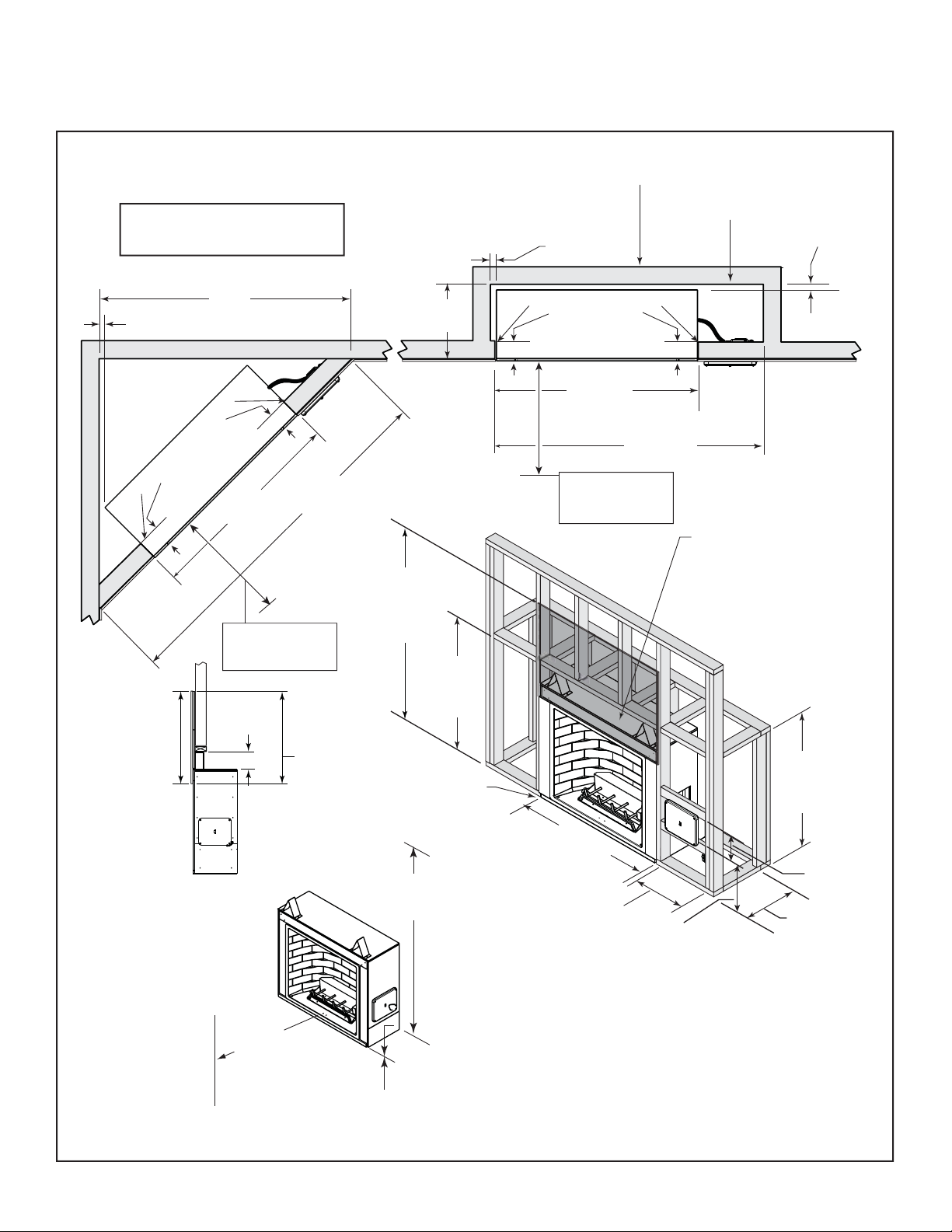
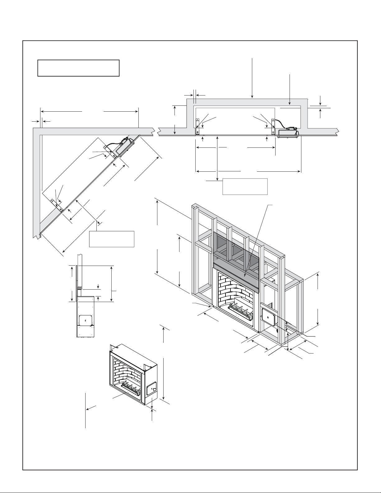
E. Clearances and Framing Dimensions
CARODG36I, CARODG36IL
Note: For actual appliance
dimensions refer to Section 12.
Note: If this surface is
inside the building’s
warm air envelope...
1 1/2 in.
(38 mm)
...then this surface
must be an exterior
wall system.
1 1/2 in.
(38 mm)
56 in.
1 1/2 in.
(1422 mm)
(38 mm)
up to 6 inches deep
Side clearances can be zero at framing,
48 in.
(1219 mm)
6 in.
36 in. minimum
(889 mm)
from appliance front
36 in. min.
noncombustible
Framing
finishing
material
6 in. min.
Front Back
NOTICE: Vinyl siding must
not be placed between the
fireplace opening and the
ceiling/overhang.
36 in.
(914 mm)
Combustible Object
Control
6 in.
79 1/4 in.
(2013 mm)
36 in. min.
cement
board from
the top of the
firebox
opening
Box
68 1/2 in.
(1740 mm)
minimum
to top of cement
board
(2083 mm)
floor to ceiling
17 in.
(432 mm)
42 3/4 in.
(1086 mm)
minimum
header height
Flashing
82 in.
0 in.
Side clearances can be zero at framing,
up to 6 inches deep
6 in.
48 in.
(1219 mm)
6 in.
Control
Box
57 in.
(1448 mm)
minimum
36 in. minimum
(889 mm)
from appliance front
Cement Board
Interior
42 1/2 in.
(1080 mm)
minimum
header height
48 in.
Exterior
(1219 mm)
11 1/2 in.
(292 mm)
minimum
10-5/8 in.
(270 mm)
8-1/4 in.
(210 mm)
17 in.
(432 mm)
Control box
MUST be
relocated!
NOTICE: Flash the perimeter of the fi replace, corners and
the fi replace face in a manner consistent with regional
practices as required to prevent water penetration around
the fi replace or manage water that may penetrate the
fi replace. See Section 3.D. for more information regarding
wall and enclosure construction.
Figure 3.1 Appliance Locations and Framing Dimensions - CARODG36I, CARODG36IL
Outdoor Lifestyles by Hearth & Home Technologies Inc. • Carolina • 4066-300 • Rev. Z • 11/13 7
Page 8
E. Clearances and Framing Dimensions
CARODG42I, CARODG42IL
Note: For actual appliance
dimensions refer to Section 12.
Note: If this surface is inside
the building’s warm air
envelope...
...then this surface must
be an exterior wall
system.
59-5/8 in.
1-1/2 in.
(38 mm)
up to 6 inches deep
Side clearances can be zero at framing,
6 in.
(1.5 m)
6 in.
54 in.
(1372 mm)
36 in. minimum
(889 mm)
from appliance front
Control
Box
82-1/4 in.
(2.1 m)
71-3/4 in.
(1.82 m)
minimum
to top of cement
board
header height
17 in.
(432 mm)
50-3/4 in.
(1.29 m)
minimum
1-1/2 in.
(38 mm)
Side clearances can be zero at framing,
up to 6 inches deep
6 in.
54 in.
(1372 mm)
63 in.
(1.6 m)
minimum
36 in. minimum
(889 mm)
from appliance front
6 in.
Control
Box
Cement Board
Interior
1-1/2 in.
(38 mm)
36 in. min. (914 mm)
noncombustible
finishing material
Front Back
Framing
6 in. min.
NOTICE: Vinyl siding must
not be placed between the
fireplace opening and the
ceiling/overhang.
36 in.
(914 mm)
Combustible Object
36 in. min. (914 mm)
cement board from
the top of the firebox
opening
0 in.
82 in.
(2.08 m)
floor to ceiling
Flashing
Exterior
50 in.
(1.27 m)
minimum
header height
54 in.
(1372 mm)
8-1/4 in.
(210 mm)
11-1/2 in.
(292 mm)
minimum
10-5/8 in.
17 in.
(432 mm)
(270 mm)
Control box
MUST be
relocated!
NOTICE: Flash the perimeter of the fi replace, corners and
the fi replace face in a manner consistent with regional
practices as required to prevent water penetration around
the fi replace or manage water that may penetrate the
fi replace. See Section 3.D. for more information regarding
wall and enclosure construction.
Figure 3.2 Appliance Locations and Framing Dimensions - CARODG42I, CARODG42IL
Outdoor Lifestyles by Hearth & Home Technologies Inc. • Carolina • 4066-300 • Rev. Z • 11/13 8
Page 9
WARNING! Risk of Fire!
Comply with all minimum
clearances to combustibles as
specifi ed. Framing or fi nish-
ing material closer than the
minimums listed must be constructed entirely of non-combustible materials (i.e., steel
studs, concrete board, etc).
Ceiling or
Overhang
minimum - one side only.
Alcove installations require
14 in. (356 mm) from each side
of the firebox opening.
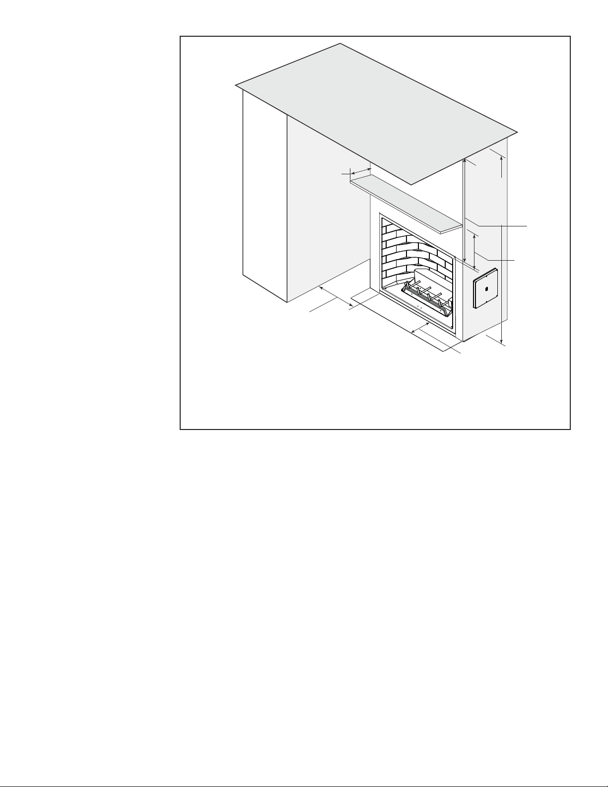
Figure 3.3 Clearances
12 in. (305 mm)
max. combustible
mantel depth
Additional Structure
or Sidewall
6 in.
(151 mm)
Fireplace Structure
Mantel
Noncombustible mat’l
deep non-combustible
hearth extension recommended
when floor in front is combustible.
82 in.
(2083 mm)
minimum
height
49-1/2 in.
(1257 mm)
minimum
25 in.
(635 mm)
minimum
16 in.
(406 mm)
Outdoor Lifestyles by Hearth & Home Technologies Inc. • Carolina • 4066-300 • Rev. Z • 11/13 9
Page 10
4
Appliance Preparation
4
CAUTION! Risk of Cuts, Abrasions or Flying Debris.
Wear protective gloves and safety glasses during installation. Sheet metal edges are sharp.
A. Securing and Leveling Appliance
Position, level, and secure the appliance.
• Place the appliance into position on either a wood or
noncombustible continuous fl at surface.
• Level the appliance from side to side and front to back.
• Shim the appliance with noncombustible material, such
as sheet metal, as necessary.
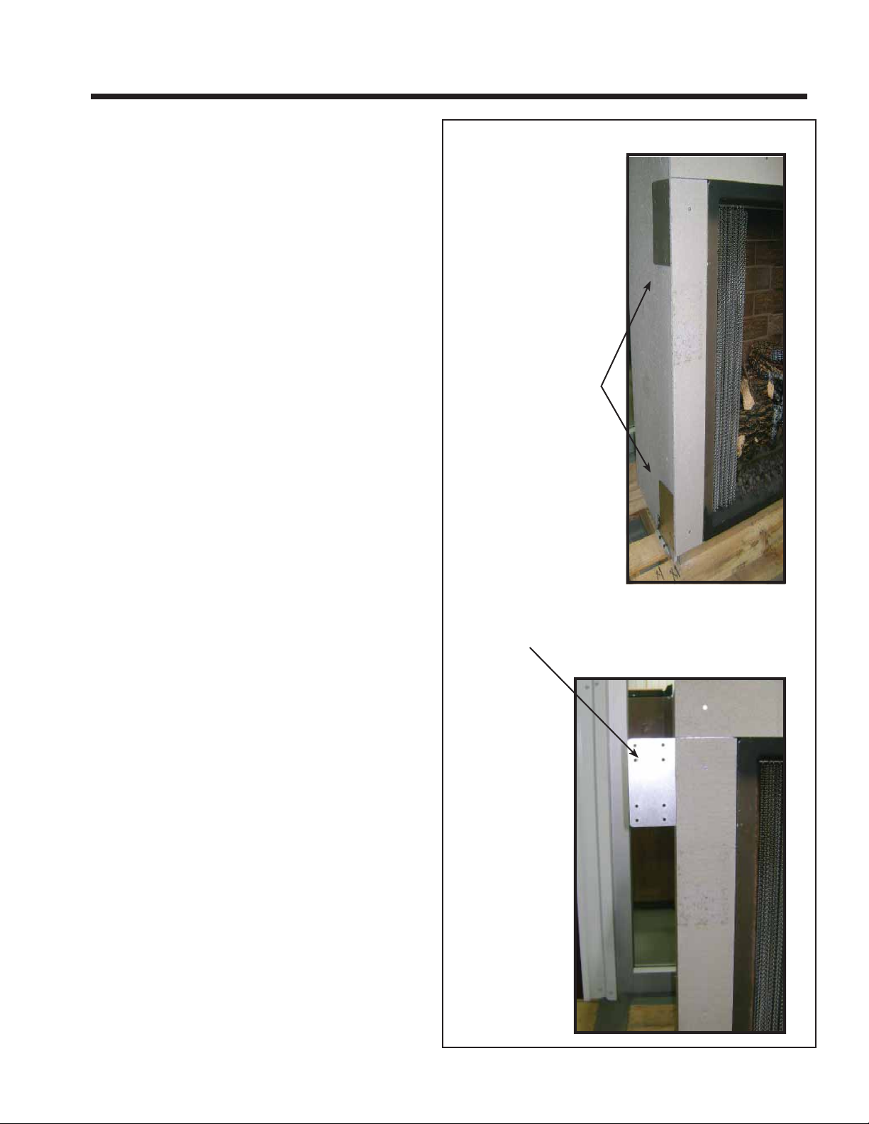
• Nailing tabs must be moved from shipping position to
installation position and secured to framing. Bend the
two nailing tabs out on each side. See Figure 4.1.
B. Flashing
• Flash the fi replace in a manner consistent with regional
practices to prevent water penetration around the
fi replace. Due to elevated temperatures across the top of
the fi replace, metal fl ashing and high temperature sealant
must be used. Adhesive polymeric fl ashing materials may
melt.
• For brick, stone, stucco and similar construction, weep
screeds should be installed per regional codes.
• See Section 3.D. and Figure 3.1 for more information
regarding wall and enclosure construction required to
prevent moisture penetration into the structure. The
fi replace will shed moderate amounts of water but is not
waterproof.
NAILING TABS IN
SHIPPING POSITION
NAILING TAB BENT OUT
(FRAMING POSITION)
Figure 4.1 Positioning and Securing Nailing Tab
Outdoor Lifestyles by Hearth & Home Technologies Inc. • Carolina • 4066-300 • Rev. Z • 11/13 10
Page 11
5
Gas Information
5
A. Fuel Conversion
Before making gas connections ensure appliance being
installed is compatible with the available gas type.
Any natural or propane gas conversions necessary to meet
the appliance and locality needs must be made by a quali-
fi ed technician using Hearth & Home Technologies speci-
fi ed and approved parts.
B. Gas Pressure
Proper input pressures are required for optimum appliance
performance. Gas line sizing requirements need to be
made following NFPA51.
WARNING
Fire Risk
Explosion Risk
High pressure will damage valve.
• Disconnect gas supply piping BEFORE
pressure testing gas line at test pressures
above 1/2 psig.
• Close the manual shutoff valve BEFORE
pressure testing gas line at test pressures
equal to or less than 1/2 psig.
Low pressure may cause explosion.
Note: A listed (and Commonwealth of Massachusetts
approved) 1/2 in. (13 mm) T-handle manual shutoff valve and
fl exible gas connector are connected to the 1/2 in. (13 mm)
control valve inlet.
• If substituting for these components, please consult
local codes for compliance.
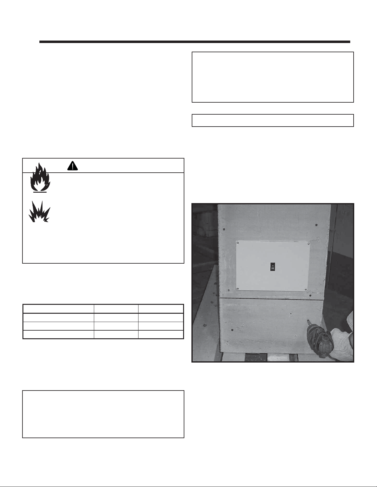
Note: Gas line MUST be run from right side of appliance.
The access panel is located below the control box. It will
be easier to make gas connection after the control box is in
its fi nal position. If necessary, relocate control box prior to
making gas connection. See Section 5.E.
• Remove the screws holding the access panel.
• Set the panel and screws aside for reinstallation.
Control Box
Pressure requirements for appliance are shown in the table
below.
Pressure Natural Gas Propane
Minimum Inlet Pressure 5.0 inches w.c. 11.0 inches w.c.
Maximum Inlet Pressure 10.0 inches w.c. 13.0 inches w.c.
Manifold Pressure 3.5 inches w.c. 10.0 inches w.c.
These pressures can be verifi ed through the access panel
as shown in Section E. Valve Access.
C. Gas Connection
Note: Have the gas supply line installed in accordance
with local building codes, if any. If not, follow ANSI
223.1. Installation should be done by a qualifi ed installer
approved and/or licensed as required by the locality. (In
the Commonwealth of Massachusetts installation must be
performed by a licensed plumber or gas fi tter.)
If control box is to be relocated, move it at this time to avoid
making the gas connection more than once.
Access Panel
Figure 5.1 Control Box & Access Panel Locations
• The incoming gas line can be installed from the bottom
of the fi replace structure, from the side or from the rear
(drilling through the cement board may be necessary).
• The incoming line should be connected to the 1/2 in.
connection on the manual shutoff valve provided with the
fi replace.
• Cut cable tie holding manual shutoff valve prior to fi nishing
to allow for easy access.
Outdoor Lifestyles by Hearth & Home Technologies Inc. • Carolina • 4066-300 • Rev. Z • 11/13 11
Page 12
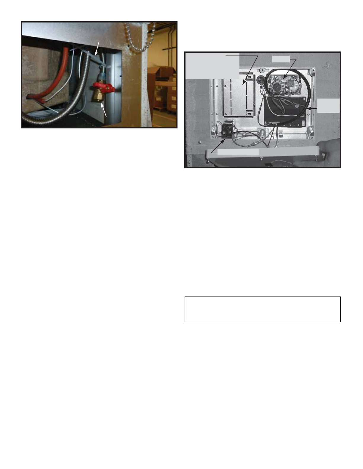
CUT CABLE TIE
CUT CABLE TIE
INCOMING GAS LINE
E. Valve Access
The valve and controls are located in the control box (Refer
to Figure 5.1). Remove the screws and remove the lid.
INCOMING GAS LINE
Figure 5.2 Connect Incoming Gas Line to Manual Shutoff Valve
• Accessibility to the shutoff valve is required after
installation, or another accessible shutoff is required.
• The fl ex line and gas shutoff valve can be accessed
after installation by removing four screws from the valve
mounting bracket at the rear of the control box.
WARNING! Risk of Fire, Explosion or Asphyxiation!
Check all fi ttings and connections with a non-corrosive
commercially available leak-check solution. DO NOT use
open fl ame. Fittings and connections could have loosened
during shipping and handling.
WARNING! Rick of Fire or Explosion! Gas build-up dur-
ing line purge could ignite.
• Purge should be performed by qualified service
technician.
• Ensure adequate ventilation.
• Ensure there are no ignition sources such as sparks or
open fl ames.
Junction Box
Mounting Bracket
(used with optional
electric kit)
Battery Holder
Figure 5.3 Control Box
Valve
Control
Module
The control box is designed to be moved out to allow for
the thickness of the fi nish material or moved from the unit
and repositioned.
• Loosen the two bolts found inside the box in the bottom
of the control box.
• Slide the box out as necessary.
• Tighten the screws.
• The control box can be removed from the appliance and
repositioned (up to approximately 6 ft. from the appliance).
• Make sure the lid will fi t over the box without interfering
with the fi nish material.
• The control box lid must be accessible and removable.
• Caulk around the perimeter of the box to prevent water
infi ltration.
Note: The control box lid can be painted as desired.
Use sandpaper or other abrasive material to scuff
D. Electrical Codes
the surface prior to painting.
If the optional electrical kit is going to be used, the wiring
should be done at this time. See Section 6.A.
NOTICE: This appliance must be electrically wired and
grounded in accordance with local codes or, in the absence
of local codes, with National Electric Code ANSI/NFPA 70-
latest edition or the Canadian Electric Code CSA C22.1.
• A 110/120 VAC circuit for this product must be protected with
ground-fault circuit-interrupter protection, in compliance
with the applicable electrical codes.
• National electrical codes require a minimum of three
feet of space in front of the access panel for service
accessibility.
F. High Altitude Installations
NOTICE: If the heating value of the gas has been reduced,
these rules do not apply. Check with your local gas utility or
authorities having jurisdiction.
When installing above 2000 feet elevation:
• In the USA: Reduce input rate 4% for each 1000 feet above
2000 feet.
• In CANADA: Reduce input rate 10% for elevations
between 2000 feet and 4500 feet. Above 4500 feet, consult
local gas utility.
Check with your local gas utility to determine proper orifi ce
size.
Outdoor Lifestyles by Hearth & Home Technologies Inc. • Carolina • 4066-300 • Rev. Z • 11/13 12
Page 13

6
Electrical Information
6
A. IntelliFire Plus™ Pilot Ignition System Wiring
• This appliance is equipped with an intermittent pilot ignition
(IPI) control which operates on a 6-volt system.
• This appliance is supplied with a battery pack which is
located in the control box. A wiring diagram is shown in
Figure 6.1.
• The battery pack requires four batteries (not included).
• An optional electric kit is available. This allows the system
to be operated with 110/120 VAC instead of batteries. See
Section 6.B.
• The appliance comes standard with an OFF/ON switch
on the control box lid
• Optional RC100 wireless wall switch (OFF/ON). For use
only with the optional electric kit.
• Optional RC200 wireless remote allows fl ame adjustment
(AUX200 is not required since there is no fan used). For
use only with the optional electric kit.
Hearth & Home Technologies recommends that IntelliFire
PlusTM wireless controls be used for their features and
functionality with the IntelliFire PlusTM ignition system.
NOTICE: RC100 & RC200 must be protected from the
elements.
• The module should be in the REMOTE position. Putting
the switch in the OFF position will disable all fi replace
controls.
WARNING! Risk of Shock! Replace damaged wire with
type 105° C rated wire. Wire must have high temperature
insulation.
WARNING! Risk of Shock! Label all wires prior to discon-
nection when servicing controls. Wiring errors can cause
improper and dangerous operation. Verify proper operation
after servicing.
Pilot
assembly
Valve
GRN
ORG
BLK
Wiring
harness
WHT
Module
BLK
BRN
RED
RED
RED
Jumper
wire
External Control Switch
(Isolates batteries from system to increase battery life)
ORG
Battery
holder
BLK
RED
Figure 6.1 Intermittent Pilot Ignition (IPI) Wiring Diagram - Battery Power Only
Outdoor Lifestyles by Hearth & Home Technologies Inc. • Carolina • 4066-300 • Rev. Z • 11/13 13
Page 14

B. Control Module Operation
1. The control module has an ON/OFF/REMOTE selector
switch that must be set. See Figure 6.1 and 6.2.
OFF Position: Appliance will ignore all power inputs and
will not respond to any commands from a wall switch or
remote. The unit should be in the OFF position during
installation, service, battery installation, fuel conversion,
and in the event that the control goes into LOCK-OUT
mode as a result of an error code. The external control
switch must be in the OFF position also.
ON Position: Appliance will ignite and run continuously
in the HI fl ame setting, with no adjustment in fl ame
output. This mode of operation is primarily used for
initial installation or power outage operation with battery
backup. The external control switch must be in the ON
position also.
REMOTE Position: Appliance will initiate commands from
an optional wired wall switch and/or one of the optional
wireless remote options. The external control switch
must be in the ON position also.
2. With the module in REMOTE mode, the fl ame output
can be adjusted with the HI/LO selector switch on the
module. See Figure 6.2. Note that the control module will
always ignite the fi replace on HI and remain so for the
initial 10 seconds of operation. If the HI/LO is switched to
the LO position, the fl ame output will automatically drop
to the lowest setting after the fl ame has been established
for 10 seconds. After this 10-second period, the fl ame
can be adjusted from HI to LO with the switch.
3. The control module has a safety feature that automatically
shuts down the fi replace after nine hours of continuous
operation without receiving a command from the wall
switch or optional remote.
4. The module has the capability to recognize potential
malfunctions. If these occur, it will fail to ignite and/or
respond to a command to ignite. If it fails to ignite, turn
off the external control switch and wait fi ve seconds
and turn back on. If it fails to light the second time,
see Trouble Shooting guide. In this case, the module
may have gone into LOCK-OUT mode. In this state, it
will emit a RED/GREEN LED error code. To reset the
error code, switch the selector to OFF, and then back to
REMOTE or ON. If the ignition command again fails, the
module will emit an LED error code prior to going back
into LOCK-OUT mode. Contact your dealer for service
if this occurs.
MODULE
SELECTOR
SWITCH
NG/LP GAS-TYPE
SELECTOR SWITCH
WIRE LEAD FROM REGULATOR CONNECTS HERE
Figure 6.2 Control Module
Nine Hour Safety Shutdown Feature
The appliance has a safety feature that automatically
shuts down the fi replace after nine hours of continuous
operation without receiving a command from the wall
switch or optional remote.
Outdoor Lifestyles by Hearth & Home Technologies Inc. • Carolina • 4066-300 • Rev. Z • 11/13 14
Page 15

C. Installing the Optional Electric Kit
• Remove four screws to remove cover from the control
box.
• Make hand bends to bracket as shown in Figure 6.6:
Figure 6.6 Hand-bend Bracket
Figure 6.3 Remove Control Cover
• Remove the junction box bracket by prying loose with a
screwdriver. Remove the two screws shown in Figure 6.4.
Cut out and remove insulation from behind junction box
bracket as shown in Figure 6.5.
Remove
2 screws
Junction
Box Bracket
Figure 6.4 Remove Junction Box Bracket & Two Screws
• Fasten bracket to junction box with two screws (provided
with junction box).
Figure 6.7 Fasten Bracket to Junction Box
• Thread wire into junction box.
• Place junction box into the control box, matching holes
as shown, and fasten with the two screws removed in
Figure 6.4.
Match holes
Figure 6.8 Place & Fasten Junction Box
Figure 6.5 Cut and Remove Insulation
Outdoor Lifestyles by Hearth & Home Technologies Inc. • Carolina • 4066-300 • Rev. Z • 11/13 15
Page 16

T
O
E
/
T
T
W
• Wire the GFI receptacle as shown below:
Grounding connection
to box (if box has a
grounding terminal)
Wire
connector
Junction
box
LINE cable brings
power to the GFCI
Figure 6.9 Wire the GFI Receptacle
Yellow sticker remains
in place to cover the
LOAD terminals
WHITE
LOAD
HIT
/TENSION
/TENSI
/NEUTRE
NEU
O
HOT
STRIP GUAGE
GABARIT DE DENUDAGE
LIGNE
LINE/
WHITE
/TENSION
/NEUTRE
HOT
• Assemble the junction box.
• Disconnect the battery holder wires from the red and
black wires of the wiring harness from the switch and
module. Connect the red and black wires of the wiring
assembly included with the electric kit to the red and
black wires to the switch and module. Plug the power
supply wire into the wire assembly and then into the
outlet. See Figure 6.12.
• If installing optional remote control, disconnect the
brown module wire from the red jumper wire. See
Figure 6.12. Follow the instructions included with the
remote control.
• Replace the cover on the control box.
Figure 6.10 Assemble Junction Box
Figure 6.11 Replace Control Cover
Outdoor Lifestyles by Hearth & Home Technologies Inc. • Carolina • 4066-300 • Rev. Z • 11/13 16
Page 17

Valve
Pilot
assembly
ORGWHT
Module
Battery holder MUST be
removed to install the
optional electric kit.
RED
RED
External
Control
Switch
BLK
BRN
*
Wiring
harness
ORG
GRN
BLK
Optional Remote Control
If a remote is used, the brown module wire
*
must be disconnected from the red jumper wire.
RC200 (optional)
RC100 (optional)
Red
Jumper
wire
Battery
holder
Fuse
Optional Electric Kit
Outlet box cover
BLK
RED
Outdoor
GFI Outlet
Power
supply
Figure 6.12 Intermittent Pilot Ignition (IPI) Wiring Diagram with Optional Electric Kit and Optional Remote Control
Outdoor Lifestyles by Hearth & Home Technologies Inc. • Carolina • 4066-300 • Rev. Z • 11/13 17
Page 18

7
Finishing
7
A. Mantel Projections
Figure 7.1 shows the dimensions for mantels or other combustible projections above the fi replace opening.
Ceiling or
Overhang
12 in. (305 mm)
max. combustible
mantel depth
Fireplace Structure
Mantel
Noncombustible mat’l
WARNING! Risk of Fire! Comply with all minimum clear-
ances to combustibles as specifi ed. Framing or fi nishing
material closer than the minimums listed must be constructed entirely of noncombustible materials (i.e., steel studs,
concrete board, etc.).
Figure 7.1 Clearances to Mantels or other Combustibles above Appliance.
B. Facing Material
The appliance can be covered with any noncombustible
material. Refer to Section 1.D.
It is possible for the face of the unit above the fi replace open-
ing to show signs of soot. Clean that area as frequently as
necessary to eliminate a build up of soot or permanent discoloration. A noncombustible ledge (shelf) approximately 3
inches above the opening and a minimum of 3 inches out
from the face of the unit incorporated into the facing material
will help prevent the soot from going up the wall.
25 in.
(635 mm)
minimum
Note: The control box lid can be painted as desired.
Use sandpaper or other abrasive material to scuff
the surface prior to painting.
Outdoor Lifestyles by Hearth & Home Technologies Inc. • Carolina • 4066-300 • Rev. Z • 11/13 18
Page 19

8
Appliance Setup
NO LAVA ROCK IN THIS AREA
8
A. Clean the Appliance
Clean/vacuum any material that may have accumulated
inside the fi rebox.
B. Optional Accessories
Install approved accessories per instructions included with
accessories. Contact your dealer for a list of approved ac-
cessories.
WARNING! Risk of Fire and Electric Shock! Use ONLY
Hearth & Home Technologies-approved optional accessories with this appliance. Using non-listed accessories could
result in a safety hazard and will void the warranty.
C. Pilot Shield
Ensure the pilot shield is still in the position shown in the
photo below. Shipping could cause it to become displaced.
Figure 8.2 Install Lava Rock
HEAT
SHIELD
PILOT
SHIELD
PILOT
BRACKET
Figure 8.1 Pilot Shield Position
D. Install Lava Rock
Pour lava rock into the burner pan and cover the burner tube.
DO NOT cover the burner tube from the right grate support
to the pilot assembly. See Figure 8.2 & 8.3. There is extra
rock provided to cover the front of the fi rebox if desired.
NO LAVA ROCK IN THIS AREA
Figure 8.3 Install Lava Rock
E. Positioning the Logs
CAROLINA-36
• Place the rear log on the shelf against the appliance rear
wall. Position log as far back on the shelf as possible.
NOTICE! Do not cover area around pilot assembly with lava
rock. Too much rock will interfere with pilot fl ame ignition,
rectifi cation, and wind stability.
Outdoor Lifestyles by Hearth & Home Technologies Inc. • Carolina • 4066-300 • Rev. Z • 11/13 19
PUSH LOG TO BACK OF SHELF
Figure 8.4 Place Rear Log - Carolina-36
Page 20

• Place the left front log on the grate against the front of the
grate. Fit notch in log to grate bar as shown below.
Notch against grate
• Place the top left log into the indentations on the rear and
left front logs.
Figure 8.8 Place Top Left Log - 36
Figure 8.5 Place Left Front Log - 36
• Place right front log on the grate against the front of the
grate. Fit notches into the bottom of the log to position it
as shown in Figure 8.6
Figure 8.6 Place Right Front Log
• Place the top right log. There are fl at indentations on the
rear and right front logs to locate the top right log.
• Place the fork of the center Y log above the middle front
grate bar and rest its back on the indentation in the middle
of the rear log.
Figure 8.9 Place Center Y Log - 36
• Place the top center log as shown below.
Figure 8.10 Place Top Center Log -36
• Place the left and right center logs as shown in Figure
Figure 8.7 Place Top Right Log - 36
Outdoor Lifestyles by Hearth & Home Technologies Inc. • Carolina • 4066-300 • Rev. Z • 11/13 20
8.10
Page 21

• The use of the top rear log is optional. It could cause
sooting in high-wind areas.
Figure 8.15 Place Top Rear Log (optional)
• Place right front log on the grate against the front of the
grate. Fit notches into the bottom of the log to position it
as shown in Figure 8.6
CAROLINA-42
• Place the rear log on the shelf against the appliance rear
wall. Position log as far back on the shelf as possible.
PUSH LOG TO BACK OF SHELF
Figure 8.4 Place Rear Log - Carolina-42
• Place the left front log on the grate against the front of the
grate. Fit notch in log to grate bar as shown below.
Figure 8.6 Place Right Front Log
• Place top left log on the indentations in the front left log
and back log as shown in Figure 8.7.
Figure 8.7 Place Top Left Log
• Place the top right log on indentations in the front right
log and back log as shown in Figure 8.8 .
Notch against grate
Figure 8.5 Place Left Front Log
Outdoor Lifestyles by Hearth & Home Technologies Inc. • Carolina • 4066-300 • Rev. Z • 11/13 21
Figure 8.8 Place Top Right Log
Page 22

• Place left center log in the indentations on the front left
log and the top left log as shown in Figure 8.9.
Figure 8.9 Place Left Center Log
• Place the center log on the indentations of the right front
log and the back log as shown in Figure 8.10.
F. Place Remaining Lava Rock
• After logs have been placed spread the remainder of the
lava rock to cover the fl oor of the fi rebox.
Figure 8.10 Place Center Log
• Place the right center long on the indentations of the right
front log and the right rear log as shown in Figure 8.11.
Figure 8.11 Place Right Center Log
Outdoor Lifestyles by Hearth & Home Technologies Inc. • Carolina • 4066-300 • Rev. Z • 11/13 22
Page 23

G. Install Firescreen
Firescreen must be installed if not installing optional screen
door.
• Remove screen and screen rods from packaging.
• Lay the two sides of screen side by side, rings on top,
handles meeting in the middle.
• Insert one screen rod through the rings on top. See Figure
8.11.
• Repeat for other screen.
Insert Rod
• Fasten rod with one of the screws removed from the fi rebox
top, into the hole shown in Figure 8.12.
Figure 8.14 Fasten Screen Rod to Firebox Top
Figure 8.11 Insert Rod into Firescreen
• Remove two screws from the fi rebox top, set aside.
Screw
for
right screen
Figure 8.12 Remove Screws from Firebox Top
• Insert left end of the rod in the left screen (handle is on
the right) into the hole in the upper left fi rebox side.
Screw
for
left screen
• Repeat with the right screen.
Insert Left
Screen Rod
Figure 8.13 Insert Screen Rod
Outdoor Lifestyles by Hearth & Home Technologies Inc. • Carolina • 4066-300 • Rev. Z • 11/13 23
Page 24

9
Operating Instructions
9
A. Gas Fireplace Safety B. Your Fireplace
WARNING
HOT SURFACES!
Screens and other surfaces are hot
during operation and cool down.
Hot screens will cause burns.
• Do not touch fireplace until it is
cooled
• NEVER allow children to touch
fi replace
• Keep children away
• CAREFULLY SUPERVISE children in same area as
fi replace.
• Alert children and adults to hazards of high
temperatures.
High temperatures may ignite clothing or other
fl ammable materials.
• Keep clothing, furniture, draperies and other combustibles
away.
If you expect that small children or vulnerable adults may
come into contact with this fi replace, the following precau-
tions are recommended:
WARNING! DO NOT operate fi replace before reading and
understanding operating instructions. Failure to operate fi re-
place according to operating instructions could cause fi re or
injury.
C. Screens
• Screens are standard on the fi replace.
• Keep screens closed when in operation.
D. Before Lighting Fireplace
Before operating this fi replace for the fi rst time:
• Review proper placement of logs and lava rock.
• Install a physical barrier such as:
- A decorative fi rescreen.
- Adjustable safety gate.
• Keep remote controls out of reach of children.
• Never leave children alone near a hot fi replace, whether
operating or cooling down.
• Teach children to NEVER touch the fi replace.
• Consider not using the fi replace when children will be
present.
Contact your dealer for more information, or visit: www.
hpba.org/safety-information.
To prevent unintended operation when not using your
fi replace for an extended period of time (summer months,
vacations, trips, etc):
• Put module switch in the OFF position (Section 6.A.) to
disable all fi replace controls or;
• Remove batteries from remote controls.
• Turn off wall controls.
• Unplug 6-volt adapter plug and remove batteries.
• Turn off gas shutoff valve.
Outdoor Lifestyles by Hearth & Home Technologies Inc. • Carolina • 4066-300 • Rev. Z • 11/13 24
Page 25

E. Lighting the Appliance
Intermittent Pilot Ignition (IPI)
Lighting instructions may be found on the inside of the control box cover.
FOR YOUR SAFETY
READ BEFORE LIGHTING
WARNING: If you do not follow these instructions exactly, a fi re or explosion
may result causing property damage, personal injury or loss of life.
A. This appliance is equipped with an
intermittent pilot ignition (IPI) device
which automatically lights the burner. DO NOT try to light the burner by
hand.
B. BEFORE LIGHTING, smell all around
the appliance area for gas. Be sure to
smell next to the fl oor because some
gas is heavier than air and will settle
on the fl oor.
WHAT TO DO IF YOU SMELL GAS
• DO NOT try to light any appliance.
• DO NOT touch any electric switch; do
not use any phone in your building.
WARNING:
DO NOT CONNECT LINE VOLTAGE (110/120 VAC OR 220/240
VAC) TO THE CONTROL VALVE.
Improper installation, adjustment, alteration, service or maintenance can
cause injury or property damage. Refer to the owner’s information manual
provided with this appliance.
This appliance needs fresh air for
safe operation and must be installed
so there are provisions for adequate
combustion and ventilation air.
If not installed, operated, and maintained in accordance with the manufacturer’s instructions, this product could
expose you to substances in fuel or
fuel combustion which are known to the
State of California to cause cancer, birth
defects, or other reproductive harm.
Keep burner and control compartment
clean. See installation and operating
instructions accompanying appliance.
• Immediately call your gas supplier
from a neighbor’s phone. Follow the
gas supplier’s instructions.
• If you cannot reach your gas supplier, call the fi re department.
C. DO NOT use this appliance if any
part has been under water. Immediately call a qualifi ed service tech-
nician to inspect the appliance and
to replace any part of the control
system and any gas control which
has been under water.
CAUTION:
Hot while in operation. DO NOT touch.
Keep children, clothing, furniture, gasoline and other liquids having fl ammable
vapors away.
DO NOT operate the appliance with
fi xed glass assembly removed, cracked
or broken. Replacement of the fi xed
glass assembly should be done by a
licensed or qualifi ed service person.
NOT FOR USE
WITH SOLID FUEL
For use with natural gas and propane.
A conversion kit, as supplied by the
manufacturer, shall be used to convert
this appliance to the alternate fuel.
Also Certifi ed for Installation in a
Bedroom or a Bedsitting Room.
For assistance or additional information, consult a qualifi ed installer, ser-
vice agency or the gas supplier.
LIGHTING
INSTRUCTIONS (IPI)
1. This appliance is equipped with an ignition
device which automatically lights the burner.
DO NOT try to light the burner by hand.
GAS
VALVE
2. Wait fi ve (5) minutes to clear out any gas.
Then smell for gas, including near the fl oor. If
you smell gas, STOP! Follow “B” in the Safety
Information located on the left side of this label. If you do not smell gas, go to next step.
3. To light the burner:
Equipped with wall switch: Turn ON/OFF switch
to ON.
Equipped with remote or wall control: Press
ON or FLAME button.
Equipped with thermostat: Set temperature to
desired setting.
4. If the appliance does not light after three tries,
call your service technician or gas supplier.
TO TURN OFF
GAS TO APPLIANCE
1. Equipped with wall switch: Turn ON/OFF switch
to OFF.
Equipped with remote or wall control: Press
OFF button.
Equipped with thermostat: Set temperature to
lowest setting.
2. Service technician should turn off electric
power to the control when performing service.
593-913G
Hearth & Home Technologies fi replace, please refer to www.fi replaces.com.
For additional information on operating your
Final inspection by
Outdoor Lifestyles by Hearth & Home Technologies Inc. • Carolina • 4066-300 • Rev. Z • 11/13 25
Page 26

F. After the Appliance is Lit
Initial Break-in Procedure
When you light the appliance, you may notice that it produces heat which does have an associated odor or smell.
This appliance should be run three to four hours on the
initial start-up. Turn it off and let it cool completely. Run the
appliance for an additional 12 hours. This will help cure the
products used in the paint and logs.
WARNING! Risk of Fire or Burns!
ance for service access. Due to high temperatures, the appliance should be located out of traffi c and away from fur-
niture and draperies.
WARNING! DO NOT place combustible objects in front of
the fi replace. High temperatures may start a fi re.
Provide adequate clear-
Outdoor Lifestyles by Hearth & Home Technologies Inc. • Carolina • 4066-300 • Rev. Z • 11/13 26
Page 27

10
10
With proper installation, operation, and maintenance your gas appliance will provide years of trouble-free service. If you do
experience a problem, this troubleshooting guide will assist a qualifi ed service technician in the diagnosis of a problem and
the corrective action to be taken. This troubleshooting guide can only be used by a qualifi ed service technician. Contact
your dealer to arrange a service call by a qualifi ed service technician.
Trou blesho oting
A. IntelliFire Plus™ Ignition System
Symptom Possible Cause Corrective Action
1. Pilot won’t light.
The ignitor/module
makes noise, but no
spark.
2. Pilot won’t light,
there is no noise or
spark.
3. Pilot sparks, but
Pilot will not light.
A. Incorrect wiring. Verify “S” wire (white) for sensor and “I” wire (orange) for ignitor are
connected to correct terminals on module and pilot assembly.
B. Loose connections or electrical
shorts in the wiring.
C. Ignitor gap is too large. Verify gap of igniter to right side of pilot hood. The gap should be
A. No power or transformer installed
incorrectly or depleted batteries.
B. A shorted or loose connection in
wiring confi guration or wiring har-
ness.
C. Improper wall switch wiring. Verify that 110/VAC power is “ON” to junction box.
D. Module not grounded. Verify black ground wire from module wire harness is grounded to
A. Gas supply. Verify that incoming gas line ball valve is “open”. Verify that inlet
Verify no loose connections or electrical shorts in wiring from module to pilot assembly. Verify connections underneath pilot assembly
are tight; also verify igniter and fl ame sense wires are not grounding
out to metal chassis, pilot burner, pilot enclosure, mesh screen if
present, or any other metal object.
approximately .17 in. or 1/8 in. (3 mm).
Verify that transformer is installed and plugged into module. Check
voltage of transformer at connection to module. Acceptable readings of a good transformer are between 6.4 and 6.6 volts DC. Battery power supply voltage must be at least 4 volts. If less than 4
volts, replace batteries.
Remove and reinstall the wiring harness that plugs into module.
Verify there is a tight fi t. Verify pilot assembly wiring to module. Re-
move and verify continuity of each wire in wiring harness. Replace
any damaged components.
metal chassis of appliance.
pressure reading is within acceptable limits.
B. Ignitor gap is too large. Verify gap of igniter to right side of pilot hood. The gap should be
approximately .17 in. or 1/8 in. (3 mm).
C. Module is not grounded. Verify module is securely grounded to metal chassis of appliance.
D. Pilot valve solenoid. Verify that 1.5 to 1.8 VDC is supplied to pilot solenoid from module.
If below 1.5 volts, replace module. If 1.5 volts or greater, replace
valve.
Outdoor Lifestyles by Hearth & Home Technologies Inc. • Carolina • 4066-300 • Rev. Z • 11/13 27
Page 28

Troubleshooting (continued)
Symptom Possible Cause Corrective Action
4. Pilot sparks, but Pilot will
not light.
5. Pilot lights but continues
to spark, and burner will
not ignite. (If the pilot
continues to spark after
the pilot fl ame has been lit,
fl ame rectifi cation has not
occurred.)
A. Gas supply. Verify that incoming gas line shutoff valve is “open”. Verify that inlet
B. Ignitor gap is incorrect. Verify that spark gap from ignitor to pilot hood is .17 in. or 1/8 in (3
C. Module is not grounded. Verify black ground wire from module wire harness is grounded to
D. Module voltage output is low. Verify battery voltage is at least 4 volts. Replace batteries if
A. A shorted or loose connection
in fl ame sensing rod.
B. Poor fl ame rectifi cation or
contaminated fl ame sensing
rod.
C. Module is not grounded. Verify module is securely grounded to metal chassis of appliance.
pressure reading is within acceptable limits.
mm).
metal chassis of appliance.
voltage is below 4.
Verify all connections to wiring diagram in manual. Verify
connections underneath pilot assembly are tight. Verify
connections are not grounding out to metal chassis, pilot burner,
pilot enclosure or screen if present, or any other metal object.
Verify correct pilot orifi ce is installed and gas inlet is set to
pressure specifi cations. Check pilot for soot. Clean if necessary.
Verify that wire harness is fi rmly connected to the module.
6. No pilot, no burner fl ame;
3 Flashes on the Module
Red LED.
D. Damaged pilot assembly or
contaminated fl ame sensing
rod.
E. Module. Turn ON/OFF rocker switch or wall switch to OFF position.
A. False fl ame detected. Shut off gas and power immediately and call a technician.
Verify that ceramic insulator around the fl ame sensing rod is not
cracked, damaged, or loose. Verify connection from fl ame sensing
rod to white sensor wire. Polish fl ame sensing rod with fi ne steel
wool to remove any contaminants that may have accumulated on
fl ame sensing rod. Verify continuity with a multimeter with ohms
set at lowest range. Replace pilot if any damage is detected.
Remove ignitor wire “I” from module. Place ON/OFF rocker switch
or wall switch in ON position. If there is no spark at “I” terminal
module must be replaced. If there is a spark at “I” terminal, module
is fi ne.
Outdoor Lifestyles by Hearth & Home Technologies Inc. • Carolina • 4066-300 • Rev. Z • 11/13 28
Page 29

11
11
Although the frequency of appliance servicing and maintenance will depend on use and the type of installation, a qualifi ed
service technician should perform an appliance check-up at the beginning of each heating season.
Maintaining and Servicing the Appliance
WARNING
Risk of injury or property damage
Before servicing:
• Turn off gas.
• Turn off electricity to appliance.
• Disable remote control, if one is present.
• Ensure appliance is completely cooled.
After Servicing:
• Replace any screen or barrier that was
removed.
WARNING
Annual inspection by qualified technician
recommended.
Check:
• Condition of screen doors.
• Obstructions of combustion and ventilation
air.
• Condition of logs.
• Condition of fi rebox.
• Burner ignition and operation.
Clean:
• Air passageways, control compartment.
• Burner, burner ports.
Risk of:
• Fire
• Delayed ignition or explosion
• Exposure to combustion fumes
• Odors
The logs, pilot assembly and front of appliance should be
checked periodically for accumulation of soot. Clean pilot
and front thoroughly with a cloth. Logs may be vacuumed
gently.
Outdoor Lifestyles by Hearth & Home Technologies Inc. • Carolina • 4066-300 • Rev. Z • 11/13 29
Page 30

A. Maintenance and Service Tasks
Inspect Maintenance Tasks
Doors and surrounds 1 Inspect for scratches and nicks that can lead to rust when exposed to weather
2 Wipe face and fi nish material. Use a degreaser to remove soot buildup, if necessary.
Valve compartment 1 Vacuum and wipe out dust, cobwebs, debris or pet hair. Use caution when cleaning these areas. Screw tips that
Logs 1 Inspect for broken, damaged or missing logs. Replace as necessary.
Firebox 1 Inspect for paint condition, warping, corrosion or perforation. Sand and repaint as necessary.
Burner ignition and
operation
Remote controls 1 Verify operation of remote.
have penetrated the sheet metal are sharp and should be avoided.
2 Remove any foreign objects.
3 Verify unobstructed air circulation.
2 Logs will accumulate soot. Periodically brush soot from the logs with a paint brush or vacuum.
2 Replace appliance if fi rebox has been perforated.
3 Check caulking around gas line and pilot assembly and replace as necessary to prevent water infi ltrating the
appliance.
1 Verify burner is properly secured to fi rebox bottom.
2 Clean off burner top, inspect for plugged ports, corrosion or deterioration.
3 Verify air shutter is clear of dust and debris.
4 Inspect orifi ce for soot, dirt or corrosion.
5 Verify manifold and inlet pressures. Adjust regulator as required.
6 Inspect pilot fl ame strength. Clean or replace orifi ce as necessary.
7 Inspect thermocouple/thermopile or IPI sensor rod for soot, corrosion and deterioration. Polish with fi ne steel wool
or replace as required.
2 Replace batteries in remote transmitters.
3 If appliance will not be used for a long period of time, verify batteries have been removed from battery back-up in
IPI systems to prevent premature battery failure or leaking.
Outdoor Lifestyles by Hearth & Home Technologies Inc. • Carolina • 4066-300 • Rev. Z • 11/13 30
Page 31

12
12
Reference Materials
A. Appliance Dimension Diagram
Dimensions are actual appliance dimensions. Use for reference only. For framing dimensions and clearances refer to
Section 3.
CARODG36I, CARODG36IL
44 in.
(1118 mm)
15-1/2 in.
(394 mm)
28-7/8 in.
(734 mm)
TOP VIEW
STANDOFFS CAN BE REMOVED
IF NOT INSTALLED IN A WALL
33-3/8 in.
(848 mm)
15 in.
(381 mm)
NON-COMBUSTIBLE BOARD
9-1/2 in.
(241 mm)
2-1/4 in.
(57 mm)
11-1/2 in.
(292 mm)
10 in.
(254 mm)
42-1/2 in.
(1080 mm)
36-1/2 in.
(927 mm)
FRONT
5-1/8 in.
(130 mm)
BOTTOM VIEW
GAS ACCESS LOCATION ON APPLIANCE
IF CONTROL BOX IS LOCATED ON SIDE OF APPLIANCE
Figure 12.1 Appliance Dimensions - CARODG36I, CARODG36IL
Outdoor Lifestyles by Hearth & Home Technologies Inc. • Carolina • 4066-300 • Rev. Z • 11/13 31
6 in.
(152 mm)
6 in.
(152 mm)
3/4 in.
(19 mm)
Page 32

CARODG42I, CARODG42IL
(1270 mm)
50 in.
15-1/2 in.
(394 mm)
STANDOFFS CAN BE REMOVED
34-3/4 in.
(883 mm)
IF NOT INSTALLED IN A WALL
15 in.
(381 mm)
NON-COMBUSTIBLE BOARD
9-1/2 in.
(241 mm)
11-1/2 in.
(292 mm)
10 in.
(254 mm)
44-1/2 in.
(1130 mm)
50-1/2 in.
(1283 mm)
39-1/8 in.
(994 mm)
FRONT
5-1/8 in.
(130 mm)
BOTTOM VIEW
GAS ACCESS LOCATION ON APPLIANCE
IF CONTROL BOX IS LOCATED ON SIDE OF APPLIANCE
Figure 12.2 Appliance Dimensions - CARODG42I, CARODG42IL
2-1/4 in.
(57mm)
6 in.
(152 mm)
6 in.
(152 mm)
3/4 in.
(19 mm)
Outdoor Lifestyles by Hearth & Home Technologies Inc. • Carolina • 4066-300 • Rev. Z • 11/13 32
Page 33

B. Service Parts List
Service Parts
CARODG36I, CARODG36IL
10
10.2
10.1
Carolina 36” Outdoor
Gas Fireplace
8
9
9.1
9.2
13
Beginning Manufacturing Date: Sept 2009
Ending Manufacturing Date: Active
#16 Non Combustible Board
16.1
16.2
16.6
16.3
16.3
16.4
11
12
Log Set Assembly
6
5
14
15
7
6
1
4
16.7
3
16.5
2
Part number list on following page.
10/13
Outdoor Lifestyles by Hearth & Home Technologies Inc. • Carolina • 4066-300 • Rev. Z • 11/13 33
Page 34

Service Parts
IMPORTANT: THIS IS DATED INFORMATION. Parts must be ordered from a dealer or distributor. Hearth and
Home Technologies does not sell directly to consumers. Provide model number and serial number when
requesting service parts from your dealer or distributor.
ITEM DESCRIPTION COMMENTS PART NUMBER
Log Set Assembly, Ships in 1 Box
1 Log 1, Back
2 Log 2, Front Right
3 Log 3, Front Left
4 Log 4, Top Inside Right
5 Log 5, Top Inside Left
Log 6, Top Outside Left Qty 2 req 4066-315
6
Log 8, Top Back 4066-313
7
Standoff Qty 2 req 4066-119
8
Burner/Grate Assembly NG
9
Burner/Grate Assembly LP
9.1
9.2
10.1 Screen Rod
10.2
11 Pilot Bracket
12 Pilot Shield 4066-127
13 Heat Shield
14 Control Box Assembly
15 Valve Assembly
16.1 Top 4066-120
16.2 Left Side 4066-121
16.3 Back Qty 2 req 4066-123
16.4 Right Side 4066-122
16.5
16.6
16.7
Additional service part numbers appear on following page.
Orifi ce, NG 4066-154
Orifi ce, LP 4066-155
Connector
Screen Assembly Qty 2 req 4066-023
Lower Right
Upper Front
Front Sides
Touch up Paint Fiber STRATFORD-KIT
Patch Kit, Fiber SRV-PACK
Conversion Kit NG NGK-CARODG36
Conversion Kit LP LPK-CARODG36
Pilot Orifi ce NG 593-528
Pilot Orifi ce LP 593-527
Regulator NG NGK-DXV-50
Regulator LP LPK-DXV-50
CARODG36I, CARODG36IL
Beginning Manufacturing Date: Sept 2009
Ending Manufacturing Date: Active
4066-017
4066-320
4066-319
4066-318
4066-317
4066-316
Pre SN 0022401504 SRV4066-019
Post SN 0022401504 4066-019
Pre SN 0022401504 SRV4066-018
Post SN 0022401504 4066-018
4066-156
Pre April 2012 4066-305
Post April 2012 4067-305
4067-112
4067-113
4066-325
Refer to valve page
4066-126
4066-124
Qty 2 req 4066-125
Stocked
at Depot
Y
Y
Y
Y
Y
Y
Y
Y
Y
Y
Y
Y
Y
Y
Y
Outdoor Lifestyles by Hearth & Home Technologies Inc. • Carolina • 4066-300 • Rev. Z • 11/13 34
Page 35

Service Parts
CARODG42I, CARODG42IL
9
9.2
9.1
Carolina 42” Outdoor
Gas Fireplace
Beginning Manufacturing Date: Mar 2010
Ending Manufacturing Date: Active
7
8
8.1
8.2
#14 Non Combustible Board
14.1
14.2
14.6
14.7
14.3
14.3
14.4
14.5
11
12
10
Log Set Assembly
6
2
13
15
5
6
1
4
6
3
Part number list on following page.
10/13
Outdoor Lifestyles by Hearth & Home Technologies Inc. • Carolina • 4066-300 • Rev. Z • 11/13 35
Page 36

Service Parts
IMPORTANT: THIS IS DATED INFORMATION. Parts must be ordered from a dealer or distributor. Hearth and
Home Technologies does not sell directly to consumers. Provide model number and serial number when
requesting service parts from your dealer or distributor.
CARODG42I, CARODG42IL
Beginning Manufacturing Date: Mar 2010
Ending Manufacturing Date: Active
ITEM DESCRIPTION COMMENTS PART NUMBER
Log Set Assembly, Ships in 2 Boxes
1 Log 1, Rear Log, Box 2
2 Log 2, Left Front, Box 1
3 Log 3, Right Front, Box, 1
Log 4, Top Right, Box 2 4067-316
4
5 Log 5, Top Left, Box 2
6 Log 6, Box 1
Standoff Qty 2 req 4067-119
7
Burner/Grate Assembly NG 4067-019
8
Burner/Grate Assembly LP 4067-018
8.1
8.2
9.1
9.2
10 Pilot Bracket 4067-112
11
12 Pilot Shield
13 Control Box Assembly
14 Non-combustible Board
14.1
14.2
14.3
14.4
14.5 Lower Right
14.6 Upper Front
14.7 Front Sides
Orifi ce, NG 4067-154
Orifi ce, LP 4067-155
Connector
Screen Rod Qty 2 req 4067-305
Screen Assembly Qty 2 req 4067-023
Heat Shield 4067-113
To p 4067-120
Left Side 4067-121
Back Qty 2 req 4067-123
Right Side 4067-122
Qty 3 req 4067-319
Qty 2 req 4067-125
4067-017
4067-313
4067-314
4067-315
4067-317
4066-156
4066-127
4066-325
4066-126
4067-124
Stocked
at Depot
Y
Y
Y
Y
Y
Y
Y
Bracket, Junction Box
Patch Kit, Fiber SRV-PACK
Touch up Paint, Fiber STRATFORD-KIT
Wire Assembly 4021-711
Conversion Kit NG NGK-CARODG42
Conversion Kit LP LPK-CARODG42
Pilot Orifi ce NG 593-528
Pilot Orifi ce LP 593-527
Regulator NG NGK-DXV-50
Regulator LP LPK-DXV-50
Additional service part numbers appear on following page.
Outdoor Lifestyles by Hearth & Home Technologies Inc. • Carolina • 4066-300 • Rev. Z • 11/13 36
4066-116
Y
Y
Y
Y
Y
Y
Y
Page 37

Service Parts
CARODG36I, CARODG42I
Beginning Manufacturing Date: Sept 2009
Ending Manufacturing Date: Active
#15 Valve Assembly
15.1
15.2
15.3
IMPORTANT: THIS IS DATED INFORMATION. Parts must be ordered from a dealer or distributor. Hearth and
Home Technologies does not sell directly to consumers. Provide model number and serial number when
requesting service parts from your dealer or distributor.
15.13
15.4
15.12
15.11
15.5
15.10
15.6
15.9
15.8
15.7
Stocked
at Depot
ITEM DESCRIPTION COMMENTS PART NUMBER
15.1 Gasket , Pilot Bracket 4066-328
15.2 Male Elbow 4021-045
15.3
15.4
SS Flex Line
Pilot Assembly NG 4021-628
Pilot Assembly LP 4021-629
Pilot Tube 4021-705
15.5
Battery Pack**
15.6 Wire Assembly
15.7 On/ Off Switch
15.8 Wire Assembly
15.9 Module
15.10
Valve Bracket 4066-115
15.11 Flex Ball Valve Assembly
15.12
15.13
90 Degree Elbow 4021-373
Valve NG 2166-302
Valve LP 2166-303
Wire Harness 2166-304
Electric Conversion Kit to AC Power ELEC-CARODG
Power Supply 2166-305
Wire Assembly 4021-711
Wire Harness 2166-304
Orifi ce, NG
Orifi ce, LP 4066-155
Orifi ce, NG
Orifi ce, LP 4067-155
CARODG36i
CARODG42i
**Fuse for battery pack can be sourced locally, not a warranty item. Specs are 500mA~10A 3/4” long
Outdoor Lifestyles by Hearth & Home Technologies Inc. • Carolina • 4066-300 • Rev. Z • 11/13 37
4021-696
2166-323
4021-697
060-511
4021-697
2166-307
2078-022
4066-154
4067-154
Y
Y
Y
Y
Y
Y
Y
Y
Y
Y
Y
Y
Y
Y
Y
Y
Y
Y
Y
Page 38

C. Warranty
Outdoor Lifestyles by Hearth & Home Technologies™
Limited Warranty
Hearth & Home Technologies (“HHT”) extends the following warranty for all Outdoor Lifestyles by HHT™
brand products (“Products”) that are purchased from an HHT authorized dealer.
WARRANTY COVERAGE:
HHT warrants to the original owner of the Product at the site of installation, and to any transferee taking
ownership of the Product at the site of installation within one year following the date of original purchase,
that the Product will be free from defects in materials and workmanship at the time of manufacture. After
installation, if covered components manufactured by HHT are found to be defective in materials or
workmanship during the applicable warranty period, HHT will, at its option, repair or replace the covered
components. This warranty is subject to conditions, exclusions and limitations as described below.
WARRANTY PERIOD:
The warranty period runs for one year, beginning on the earlier of: (i) the date of invoice for the Product;
(ii) in the case of new home construction, the date of first occupancy of the residence or six months after
the date of sale of the Product by an HHT authorized dealer, whichever occurs first; or (iii) the date 24
months following the date of Product shipment from HHT, regardless of the invoice or occupancy date.
WARRANTY CONDITIONS:
• This warranty only covers Products that are purchased through an HHT authorized dealer or
distributor. A list of HHT authorized dealers is available on the HHT branded websites.
• This warranty is only valid while the Product remains at the site of original installation.
• Contact your installing dealer for warranty service. If the installing dealer is unable to provide
necessary parts, contact the nearest HHT authorized dealer or supplier. Additional service fees
may apply if you are seeking warranty service from a dealer other than the dealer from whom
you originally purchased the Product.
• Check with your dealer in advance for any costs to you when arranging a warranty call. Travel
and shipping charges for parts are not covered by this warranty.
WARRANTY EXCLUSIONS:
This warranty does not cover the following:
• Changes in surface finishes as a result of normal use. As a heating appliance, some changes in
color of interior and exterior surface finishes may occur; this is not a flaw and not covered under
warranty.
• Damage to printed, plated, or enameled surfaces caused by fingerprints, accidents, misuse,
scratches, melted items, or other external sources and residues left on surfaces from the use of
abrasive cleaners or polishes.
• Repair or replacement of parts that are subject to normal wear and tear during the warranty
period. These parts include: paint, firebricks, grates, flame guides and the discoloration of glass.
• Minor expansion, contraction, or movement of certain parts causing noise. These conditions are
normal and complaints related to this noise are not covered by this warranty.
Outdoor Lifestyles Warranty - 2108-975B - 2/15/13 - page 1
Outdoor Lifestyles by Hearth & Home Technologies Inc. • Carolina • 4066-300 • Rev. Z • 11/13 38
Page 39

C. Warranty (continued)
• Damages resulting from: (1) failure to install, operate, or maintain the Product in accordance with
the installation instructions, operating instructions, and listing agent identification label furnished
with the Product; (2) failure to install the Product in accordance with local building codes; (3)
shipping or improper handling; (4) improper operation, abuse, misuse, continued operation with
damaged, corroded or failed components, accident, or incorrectly performed repairs; (5) inadequate ventilation, negative pressure or environmental conditions, including, without limitation:
hail, snow, ice, fallen branches, flooding, water damage and fading of color; (6) use of fuels other
than those specified in the operating instructions; (7) installation or use of components not
supplied with the Product or any other components not expressly authorized and approved by
HHT; (8) modification of the Product not expressly authorized and approved by HHT in writing;
and/or (9) interruptions or fluctuations of electrical power supply to the Product.
• Non-HHT venting components, hearth components or other accessories used in conjunction with
the Product.
• Any part of a pre-existing fireplace system in which an insert or a decorative gas appliance is
installed.
• The Product’s capability to heat the desired space. Information is provided to assist the consumer
and the dealer in selecting the proper appliance for the application. Consideration must be given
to the Product’s location and configuration and environmental conditions.
This warranty is void if:
• The Product has been over-fired or operated in atmospheres contaminated by chlorine, fluorine,
or other damaging chemicals. Over-firing can be identified by, but not limited to, warped plates or
tubes, rust colored cast iron, bubbling, cracking and discoloration of steel or enamel finishes and
cracking or spalling of refractory or cementitious materials.
• The Product is subjected to prolonged periods of dampness, condensation, ice or snow.
• There is any damage to the Product or other components due to water or weather damage which
is the result of, but not limited to, improper chimney or venting installation.
LIMITATIONS OF LIABILITY:
Repair or replacement in accordance with the provisions of this warranty will be the owner’s exclusive
remedy for and will constitute HHT’s sole obligation under this warranty, under any other warranty
(express or implied), or in contract, tort or otherwise; provided, however, that if HHT is unable to provide
repair or replacement in an expedient and cost effective manner, HHT may discharge all such obligations
by refunding the purchase price of the Product. No employee, agent, dealer, or other person is authorized
to give any warranty on behalf of HHT. TO THE EXTENT ALLOWED BY LAW, HHT MAKES NO OTHER
WARRANTY, EXPRESS OR IMPLIED, INCLUDING ANY WARRANTY OF MERCHANTABILITY OR
FITNESS FOR A PARTICULAR PURPOSE. HHT WILL NOT BE LIABLE FOR ANY CONSEQUENTIAL
OR INCIDENTAL DAMAGES ARISING OUT OF DEFECTS IN OR USE OF THE PRODUCTS. Some
states do not allow exclusions or limitation of incidental or consequential damages, so these limitations
may not apply to you. This warranty gives you specific rights; you also may have other rights, which vary
from state to state. The duration of any implied warranty is limited to the duration of the warranty period
specified herein.
Outdoor Lifestyles Warranty - 2108-975B - 2/15/13 - page 2
Outdoor Lifestyles by Hearth & Home Technologies Inc. • Carolina • 4066-300 • Rev. Z • 11/13 39
Page 40

D. Contact Information
Please contact your Outdoor Lifestyles dealer with any questions or concerns.
For the number of your nearest Outdoor Lifestyles dealer, please visit www.hearthnhome.com.
- NOTES -
CAUTION
DO NOT DISCARD THIS MANUAL
•
•
• Important operating
and maintenance
instructions included.
This product may be covered by one or more of the following patents: (United States) 5601073, 5613487, 5647340,
5890485, 5941237, 6006743, 6019099, 6053165, 6145502, 6374822, 6484712, 6601579, 6769426, 6863064, 7077122,
7098269, 7258116, 7470729, 8147240 or other U.S. and foreign patents pending.
Outdoor Lifestyles by Hearth & Home Technologies Inc. • Carolina • 4066-300 • Rev. Z • 11/13 40
Read, understand
and follow these
instructions for safe
installation and
operation.
Printed in U.S.A. - Copyright 2013
Leave this
manual with party
responsible for use
and operation.
DO NOT
DISCARD
2000-945B
 Loading...