

Harlequin HS200DI, HS150IN, HS250DI, HS200IN, HS250IN Installation & Maintenance Manual
...
This manual must be left with the end user
Manual
HeatStream
Installation &
Maintenance
Applicable to the following models:
Direct: HS150DI, HS200DI, HS250DI;
Indirect: HS150IN, HS200IN, HS250IN, HS400IN, HS500IN, HS600IN;
Twin: HS200TW, HS250TW, HS400TW, HS500TW, HS600TW;
Triple: HS400TR, HS500TR, HS600TR.

Pre-Installation checklist
The HeatStream family of hot water storage tanks have been developed to suit a wide range of
installations, there are however some cases where existing systems may have to be upgraded. Prior
to installing a HeatStream tank, it is recommended the following checks are carried out to ensure the
system meets the following requirements:
1) Incoming mains water supply should be capable of delivering a minimum flow rate of 20 litres
per minute at a dynamic pressure of 1.5 bar at all times. If this cannot be achieved a coldwater booster set should be installed to achieve this. It is also possible to use a gravity fed
system although flow rate performance will be significantly reduced.
2) Incoming mains water supply pressure should not exceed 3 bar. If the supply pressure is
greater than this a pressure reducer must be installed.
3) The tank is designed for the use and production of potable hot water, and other usage or
modifications will invalidate all guarantees. The incoming mains water supply should have a
total hardness of less than 200mg/litre and a chloride content of less than 300mg/litre. The
heating water should have a pH value of between 6.5 and 8.5. In instances where the water
chemistry exceeds these levels a suitable and effective water treatment should be installed.
This should be designed and installed in such a way as to minimise the risk of component and
or system failure.
4) Any circuits supplying heat to the tank and connected to an external heat source should be
fully pumped (not applicable to the direct range). Gravity circulation is only possible with the
Triple range of tanks (secondary and tertiary heat supply circuits only).
5) Pipework supplying the hot taps must be capable of withstanding minimum 6 bar pressure.
6) Pipework supplying the hot taps must be capable of carrying water with a temperature of up
to 95°C.

Page 1 of 33
CONTENTS
CONTENTS ....................................................................................................................................................... 1
1 USER INSTRUCTIONS ............................................................................................................................... 2
1.1 GENERAL ARRANGEMENT ............................................................................................................................. 2
1.2 OPERATION INSTRUCTIONS .......................................................................................................................... 3
1.3 TANK CONTROL THERMOSTAT ....................................................................................................................... 4
1.4 FREQUENT CHECKS ..................................................................................................................................... 5
2 TECHNICAL SPECIFICATIONS .................................................................................................................... 7
2.1 DIRECT ..................................................................................................................................................... 7
2.2 INDIRECT .................................................................................................................................................. 9
2.3 TWIN ..................................................................................................................................................... 11
2.4 TRIPLE ................................................................................................................................................... 13
3 INSTALLATION ....................................................................................................................................... 14
3.1 BUILDING REGULATIONS ............................................................................................................................ 14
3.2 ACCESSORY KITS ....................................................................................................................................... 14
3.3 TANK INSTALLATION .................................................................................................................................. 15
3.4 ELECTRICAL INSTALLATION ......................................................................................................................... 21
4 COMMISSIONING .................................................................................................................................. 24
4.1 FILLING THE SYSTEM.................................................................................................................................. 24
4.2 SYSTEM CONTROLS ................................................................................................................................... 25
5 MAINTENANCE ...................................................................................................................................... 26
5.1 INSPECTION ACCESS .................................................................................................................................. 26
5.2 MAINTENANCE CHECKS ............................................................................................................................. 26
5.3 TROUBLESHOOTING .................................................................................................................................. 27
5.4 REPLACEMENT PARTS................................................................................................................................ 28
5.5 DE-COMMISSIONING................................................................................................................................. 28
6 WARRANTY ........................................................................................................................................... 29
6.1 WARRANTY STATEMENT ............................................................................................................................ 29
6.2 WARRANTY REGISTRATION.......................................................................................................................... 30
7 COMMISSIONING AND SERVICE RECORDS ............................................................................................. 31
7.1 SERVICE RECORD ...................................................................................................................................... 32
Page 2 of 33
1 USER INSTRUCTIONS
1.1 GENERAL ARRANGEMENT
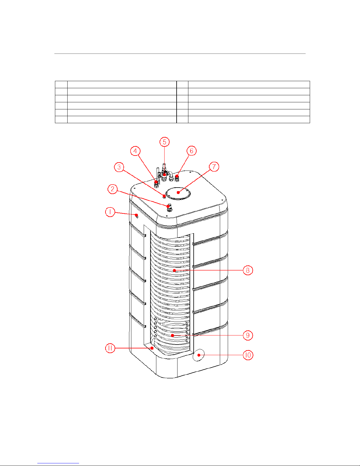
Figure 1 Key components of the HeatStream hot water storage tank
1
Overflow
7
Thermostat(s) & top immersion
2
Low level indicator
8
Hot water coil
3
Fill loop connection
9
Heat source coil
4
Heat source coil inlet
10
Bottom immersion (Direct models)
5
Mixing valve
10
Temperature probe pocket (Twin / Triple models)
6
Heat source coil outlet
11
Insulation
Page 3 of 33
1.2 OPERATION INSTRUCTIONS
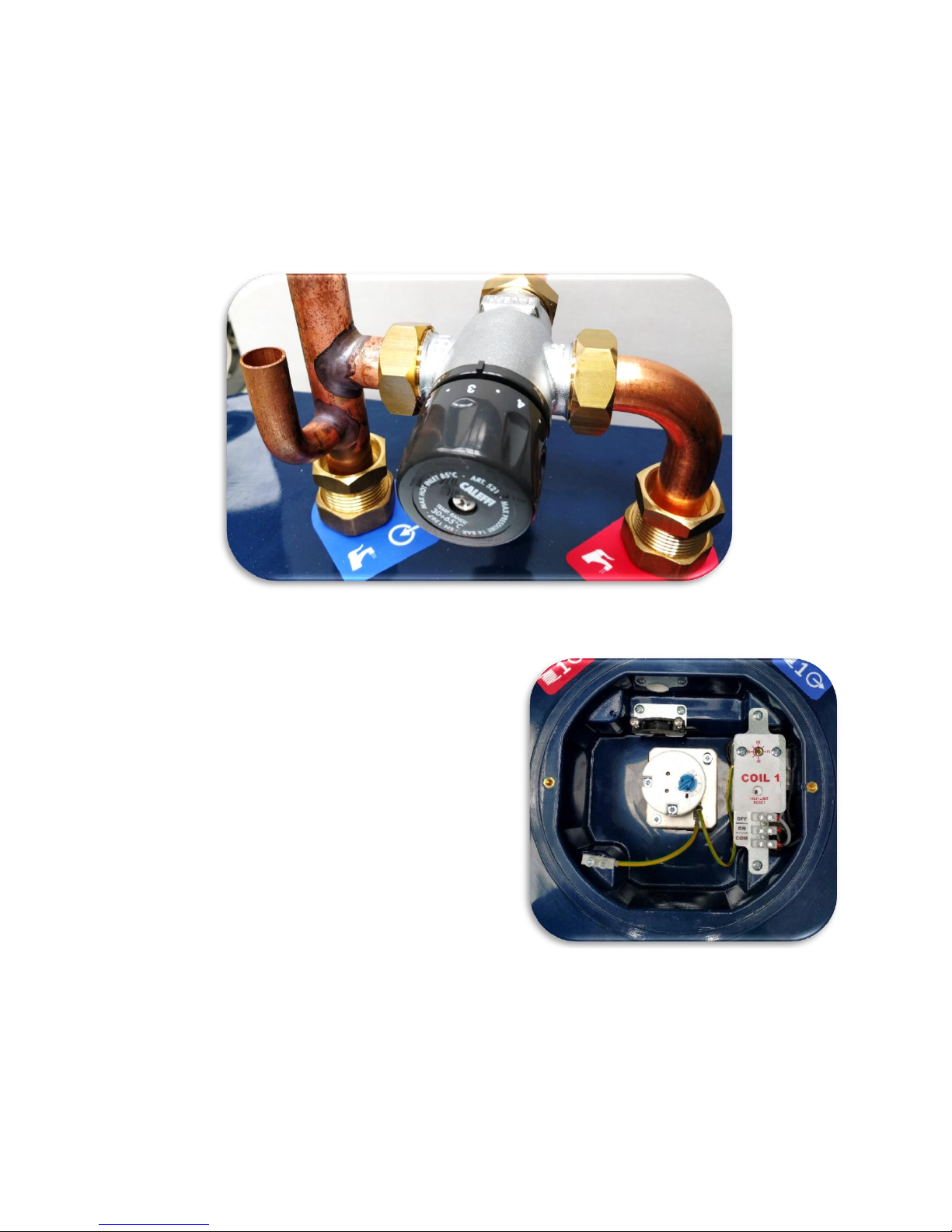
1.2.1 Thermostatic mixer
A thermostatic mixing valve (Figure 2) with an adjustment range of between 35°C (MIN) and 65°C
(MAX) is supplied with all HeatStream tanks. The function of the thermostatic mixing valve is to deliver
water consistently at a safe temperature. It is recommended that the mixing valve is set to nominally
45°C (#3) to achieve the best hot water output performance.
Figure 2 Thermostatic mixer valve settings
1.2.2 Top immersion heater
All HeatStream tanks are supplied with a top mounted
3kW immersion heater which acts as a boost / backup
to an external heat source such as a boiler. The Direct
range is electrically heated only and is supplied with an
additional 3kW immersion heater positioned at the
bottom of the tank. Each immersion heater is fitted
with a thermostat which helps to regulate the store
temperature. This is pre-set to nominally 60°C but can
be adjusted by removing the immersion heater cover
and adjusting the control knob (position 1≈15°C,
position 5≈70°C Figure 3 and Figure 4).
Each thermostat has an integrated high limit safety stat
which provides protection against the tank
overheating. In the event of the high limit temperature
being reached, power will be cut off to the immersion
heater and will require manual resetting to restore
operation, this can be reset by pressing down on the
reset button (Figure 4).
NOTE: Isolate the power supply before
removing any protective covers. If you are
unsure or need assistance seek help from a
competent person.
Figure 3 Top thermostat and immersion compartment
Page 4 of 33
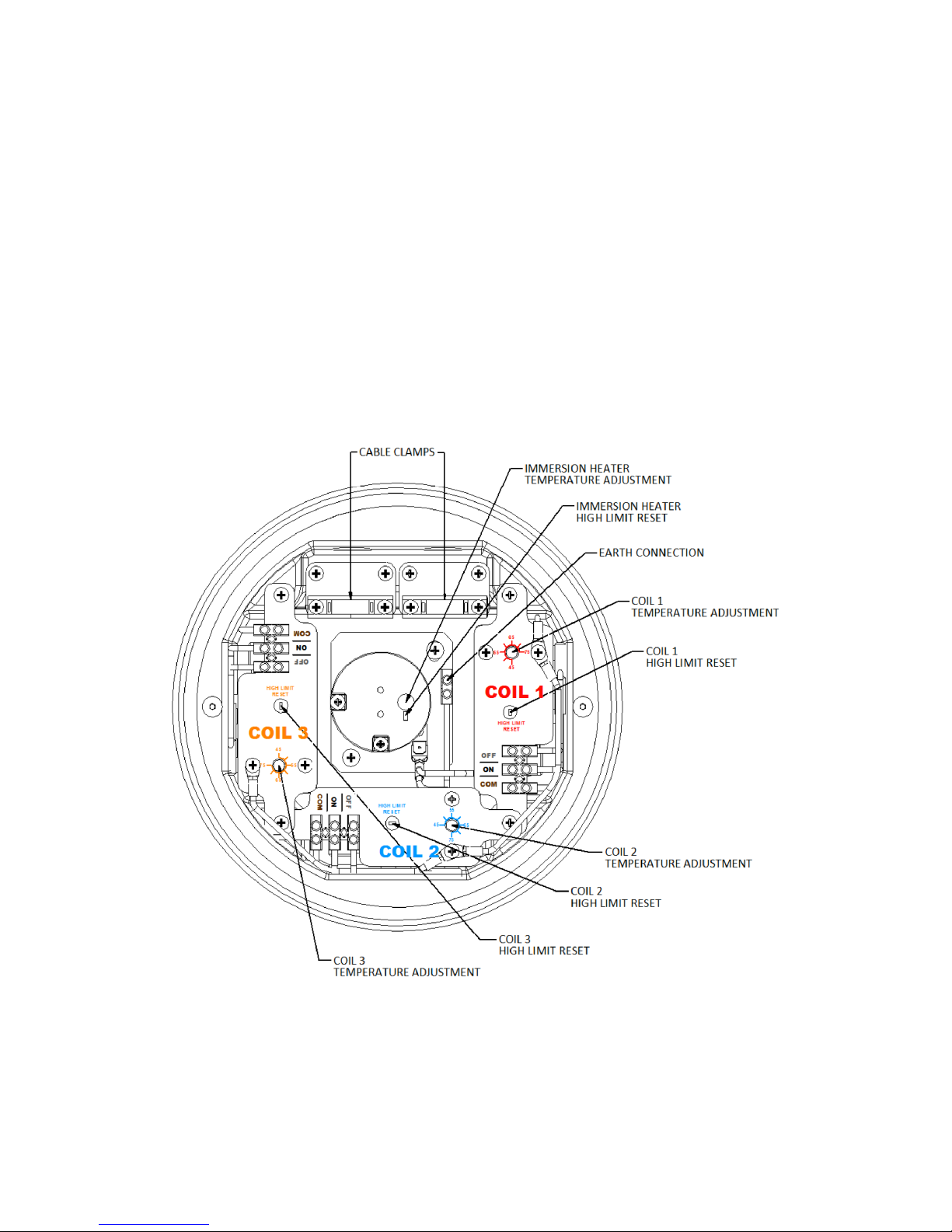
1.3 TANK CONTROL THERMOSTAT
All indirect, twin and triple tanks are fitted with thermostats to control the supply of heat to the tank
from the various heat sources. This is pre-set to nominally 65°C but can be adjusted between
nominally 45°C and 75°C dependent on the heat source and desired store temperature (Figure 4).
Each thermostat has an integrated high limit safety thermostat which provides protection against the
tank overheating. In the event of the high limit temperature being reached the supply of heat to the
tank will be cut off and will require manual resetting to restore operation, this can be reset by pressing
down on the safety reset button (Figure 4).
NOTE: Only reset the high limit trip when the tank is cold, failure to do so will irreparably
damage the thermostat.
Isolate the power supply before removing any protective covers. If you are unsure or need
assistance seek help from a competent person.
Figure 4 Location of thermostat controls
Page 5 of 33
1.4 FREQUENT CHECKS
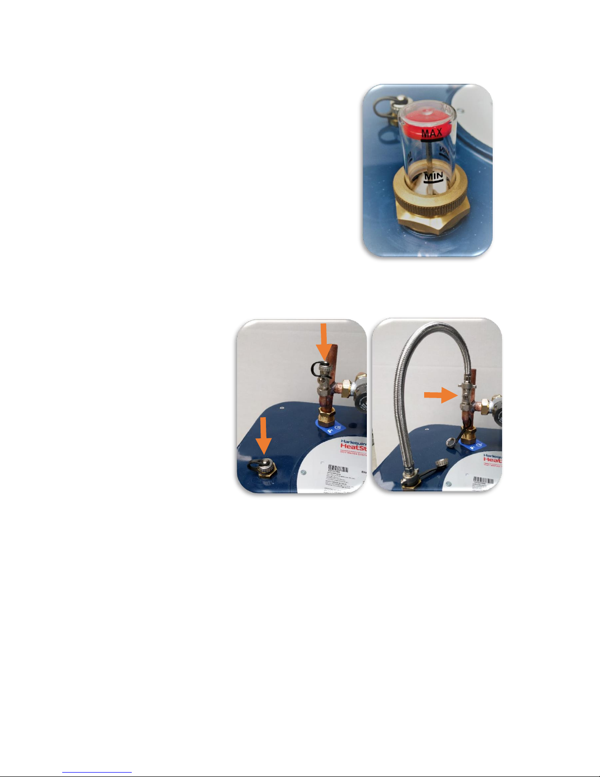
1.4.1 Low level indicator
It is important to carry out periodic visual checks via the lowlevel indicator to ensure the correct water level is maintained.
During normal operation the red indicator should be between
the MIN and MAX markings (Figure 5). If the water level is
found to be below the MIN marking it can be topped up using
the filling loop. When the filling loop is not in use, it should be
disconnected from the system.
1.4.2 Topping up the tank
If the tank level is found to be
below the MIN marking it must
be topped up using the filling
loop. Connect the flexible hose
as shown in Figure 6. Using a
flat head screwdriver turn the
ball valve (Figure 6) slowly
clockwise through 900, the
tank will begin filling, when the
level indicator reaches MAX
and water starts to flow from
the overflow close the valve.
Ensure the filling valve is fully closed and disconnect the hose, there will be a small leakage of water
so have rags handy to mop up. The caps must be screwed onto the tank and the ball valve as shown
in Figure 7. Failure to replace the caps may result in steam escaping from the tank or water leaking
from the ball valve.
NOTE: It is normal for the red indicator to drop again slightly following the first heat up
cycle. There is no need at this point to top the tank up any further, unless the red indicator
is below the MIN marking.
Figure 5 Water level indicator
Figure 7 Filling loop disconnected
Figure 6 Filling loop connected
Page 6 of 33
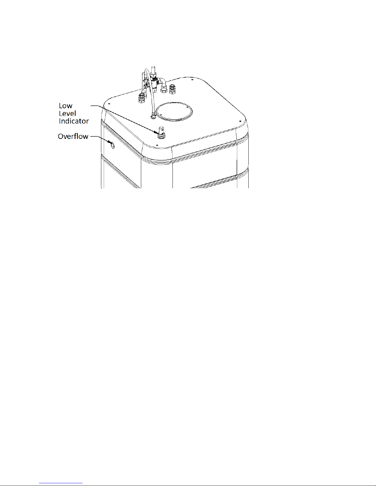
1.4.3 Tank overflow
Figure 8 Location of low level indicator and overflow
All tanks have an integral safety overflow pipe. The function of the overflow pipe is to act as a vent
and prevent any pressure build up if the tank was overfilled and or developed an internal fault. Regular
visual checks should be carried out to ensure there are no leaks and or blockages present in the
system. If water is continuously being discharged through the overflow pipe this may suggest the hot
water tank has developed a fault or that the filling loop is still connected. Check that the filling loop
hose is disconnected and the connections capped. If the fault persists, please contact your original
installer. It is normal for a small volume of water to run off through the overflow pipe during first fill
and subsequent first heat up cycle and when topping up the water inside the tank.
NOTE: If a fault is discovered switch off all heat sources, isolate the power supply and contact
your installer. Wait until the storage water has sufficiently cooled before carrying out any
repairs.
Page 7 of 33
2 TECHNICAL SPECIFICATIONS
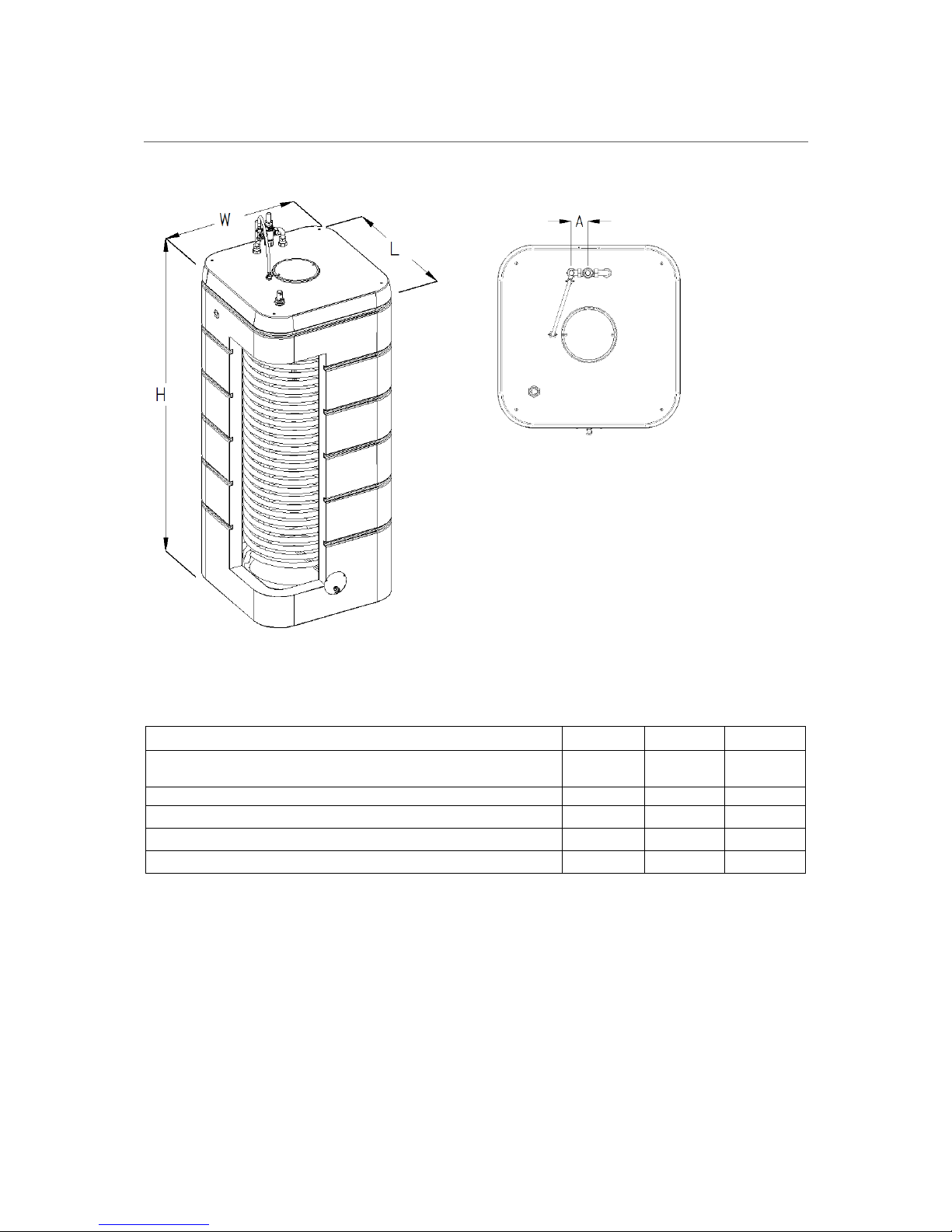
2.1 DIRECT
Table 1 HeatStream Direct specifications
PRODUCT CODE
HS150DI
HS200DI
HS250DI
Dimensions, L x W x H (mm)
520 x 520
x 1315
520 x 520
x 1650
520 x 520
x 1980
Dimension, A (mm)
70
70
70
Empty weight (kg)
36
44
52
Total filled weight (kg)
188
246
304
Volume (Litres)
152
202
252
Figure 9 HeatStream Direct dimensions
Page 8 of 33
PRODUCT CODE
HS150DI
HS200DI
HS250DI
Standing heat loss (W)
47
52
65
ErP rating
B B B
Heat up time by lower immersion (mins)
156
210
260
Heat up time by both immersions (mins)
78
105
130
Domestic hot water coil maximum operating pressure (bar)
3 3 3
Hot water quantity without reheating at 15L/min draw off rate (L)
(12°C cold water temperature)
113
188
203
Maximum permissible storage water temperature (°C)
95
95
95
Pipe connections (mm)
22
22
22
Safety overflow
G 3/4”
G 3/4”
G 3/4”
Page 9 of 33
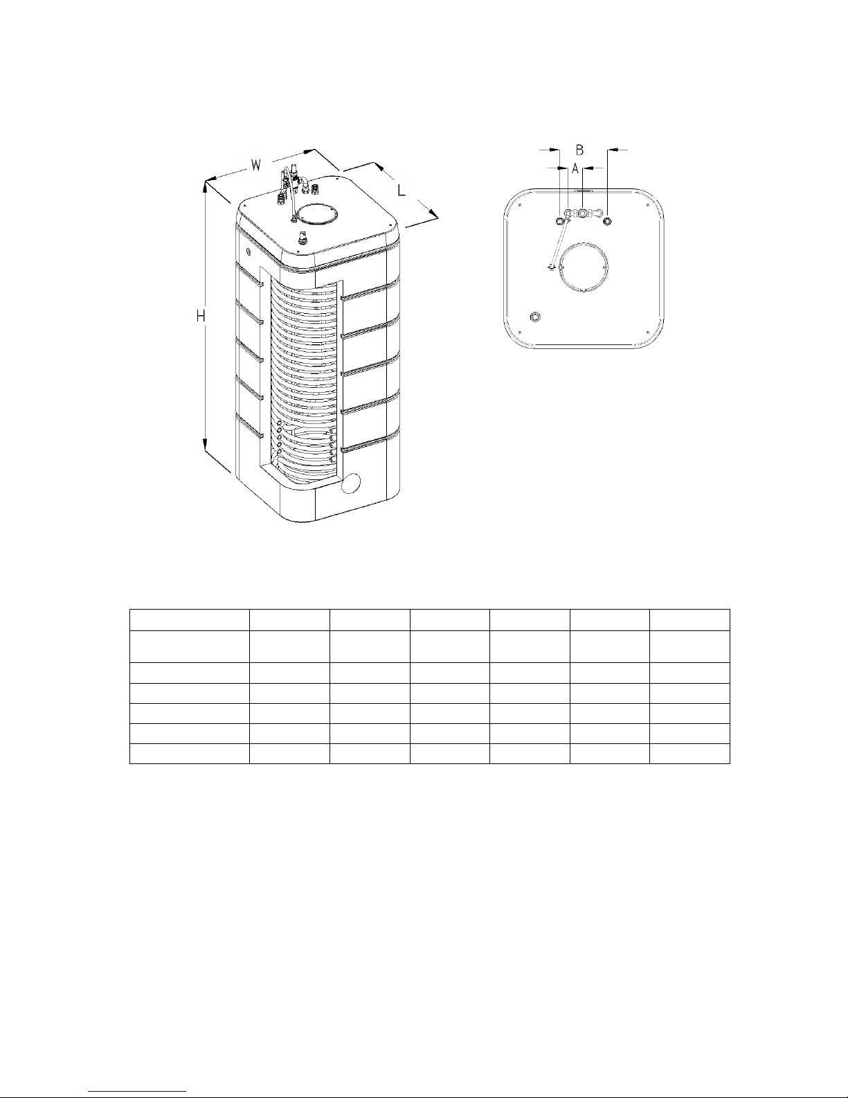
2.2 INDIRECT
Table 2 HeatStream Indirect specifications
PRODUCT CODE
HS150IN
HS200IN
HS250IN
HS400IN
HS500IN
HS600IN
Dimensions, L x W x
H (mm)
520 x 520 x
1315
520 x 520 x
1650
520 x 520 x
1980
780 x 780 x
1355
780 x 780 x
1610
780 x 780 x
1865
Dimension, A (mm)
70
70
70
70
70
70
Dimension, B (mm)
230
230
230
230
230
230
Empty weight (kg)
39
48
56
65
74
82
Filled weight (kg)
191
250
308
470
578
686
Volume (Litres)
152
202
252
405
504
604
Figure 10 HeatStream Indirect dimensions
 Loading...