

Page 1
PWRS-E.Compact
Please read these instructions carefully before operating equipment.
PowerSeat
PWRS-E
Instruction Manual
English Translation
Rev. 00 FT
UPS_30/01-2014
Page 2

Page 3

01-30-14 ENGLISH 3
Page 4

4 ENGLISH 01-30-14
Page 5

Index
Introduction
About this Manual
Glossary and Symbols
General Information
Identification Data and Plates on the Device
Model of Declaration of Compliance
Standard References
FCC Verification
IC Certification
Technical Support Information
Safety Precaution
General Advice
Intended Use
Improper Use
Safety Devices
Personal Protective Equipment (PPE)
page
page
page
page
page
page
page
page
page
page
page
page
page
page
page
page
7
7
8
9
9
10
11
12
12
12
13
13
13
14
14
14
Residual Risks
Safety Informations
Power Supply Informations
Power Supply Description
General
Dimensions
Technical Data
Light Interface
Safety Informations
Using the Power Supply
Cleaning the Power Supply
PowerSeat PWRS-E
Device Description
General
Dimensions
Safe Working Load
page
page
page
page
page
page
page
page
page
page
page
page
page
page
page
page
14
15
16
16
16
17
17
18
18
19
19
20
20
20
21
22
Rope Requirements
Vibration
Noise Emission
Technical Data
Motor
Using the Device
01-30-14 ENGLISH 5
page
page
page
page
page
page
22
22
22
22
23
23
Page 6

Index
Checking the Device Before Use
Adjusting the Accelerator Control Position
Adjusting the Control Lever Position
Primary Rope Installation Procedure
Wiring the Power Supply System
Preparing to Ascent
Ascent Procedure 1
Ascent Procedure 2
Using PowerSeat with a fixed Anchorage
Descent Procedure 1
Descent Procedure 2
Fixed Anchorage Descent Procedure
Transport and Storage
PowerSeat PWRS-E.Compact
Description of Compact version
General
page
page
page
page
page
page
page
page
page
page
page
page
page
page
page
page
23
25
26
27
29
30
32
34
35
37
38
38
38
39
39
39
Dimension
Using the Compact version Device
Checking the Compact version Device Before Use
Primaru Rope Installation Procedure on Compact version
Preparing to Ascent with the Compact version
Ascent Porcedure with the Compact version
Using Compact version PowerSeat with a Fixed Anchorage
Descent Procedure with the Compact version
Fixed Anchorage Descent Procedure with the Compact version
Converting the PowerSeat PWRS-G inthe Compact version
Maintenance
Cleaning
Maintenance
Dismalting and Disposal
Diagnosis and Fault Finding
page
page
page
page
page
page
page
page
page
page
page
page
page
page
page
40
41
41
41
43
43
44
46
46
46
48
48
48
48
49
PowerSeat and Motor
Power Supply
Maintenance Schedule
Worldwide Limitied Warranty
6 ENGLISH 01-30-14
page
page
page
page
49
49
50
54
Page 7

Introduction
ABOUT THIS MANUAL
This User Manual is an integral part of the device and aims to provide all the information needed for its safe
and correct use and for proper maintenance.
If there are instructions you do not understand, contact Harken.
Keep the manual in a safe place for future consultation. This manual may be modified without notice. Updated
versions are available on www.power-seat.com.
This manual is for qualified operators (refer to the Safety Information chapter for more information). Improper
use of the device or incorrect maintenance could cause severe damage or death.
Harken accepts no responsibility for damage, personal injury or death caused by failure to observe the safety
information and instructions in this Manual. The device must be used exclusively by qualified operators in
possession of a certificate for temporary work at height with the use of access and positioning systems using
ropes according to the current regulations of the Nation in which the device is used. This manual thus supplies
information exclusively regarding the correct use of the device and does not substitute the training and
certification needed for temporary work at height with the use of access and positioning systems using ropes.
01-30-14 ENGLISH 7
Page 8
Introduction
GLOSSARY AND SYMBOLS
Intended Use – use of the device according to the information supplied in the instructions for use.
Improper Use – use of the device in a way different from that indicated in the instructions for use.
Qualified Operator – persons who have attended specialisation, training etc courses and are certified for
temporary work at height with the use of access and positioning systems using ropes according to the
current regulations of the Nation in which the device is used.
User – qualified operator of the device
Anchorage – point of attachment of the rope or device to a fixed point.
Primary (working) rope – main rope used for ascending or descending using the device (approved
according to EN 1891).
Secondary (backup) rope – safety rope to protect the operator from falling if the primary rope breaks
(approved according to EN 1891).
Fall Arrest – individual protection device that brakes the fall of the user (EN353/2 approved).
Text preceded by the following symbols contains very important information or instructions, especially
in regards to safety.
Failure to observe these may lead to:
danger for operators
invalidity of the contract warranty
refusal of the manufacturer to accept responsability
WARNING!
this denotes the existence of the potential danger, which could cause injury or damage if the information or instructions are not followed
NOTE!
this denotes important information concerning the device
8 ENGLISH 01-30-14
Page 9
General Information
i
PWRS-E/PWRS-E.Compact
Serial No. / N. di serie
rope di ameter
diametr o fune
2006/42/EC
2004/108/EC
Safe Working Load (SWL)
300 kg
via Marco Biagi, 14
22070, Limido Comasco (CO) - Italy
www.harken.com
(+39) 031 3523511
PowerSeat
ø 10-12,7 mm EN1891
Year/Anno
AAAA
i
PWRS-E/PWRS-E.Compact
Serial No. / N. di serie
rope diameter
diametro fune
2006/42/EC
2004/108/EC
Safe Working Load (SWL)
300 kg
via Marco Biagi, 14
22070, Limido Comasco (CO) - Italy
www.harken.com
(+39) 031 3523511
PowerSeat
ø 10-12, 7 mm EN1891
Year/Anno
AAAA
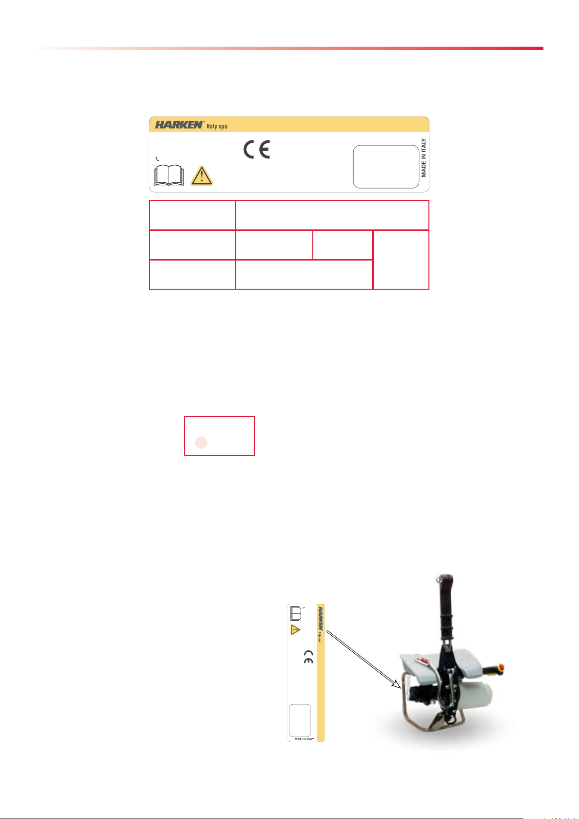
IDENTIFICATION DATA AND PLATES ON THE DEVICE
Each device is identified by a CE plate on which the reference data of the device are inscribed indelibly. Always
quote these references when contacting the manufacturer or service centres.
1
3
4 5
2
6
7 8
1. name of manufacturer
2. name of product and model
3. manufacturer's identification data
4. CE mark according to 2006/42/CE
5. year of manufacture
6. serial number in the format:
S XXXXX
XXXXXXXXX
last two numbers of the year of manufacture of the device (e.g. 13 = the year 2013)
7. pictogram instructing you to read the manual before using the device
8. safety instruction on the diameter of the rope to use: minimum 10 mm, maximum 12.7 mm: this rope must
be EN 1891 certified, plus indication of the Safe Working Load (SWL) of the device
The CE plate is on the chassis of the device:
01-30-14 ENGLISH 9
Page 10

General Information
MODEL FOR DECLARATION OF COMPLIANCE
DECLARATION OF EC COMPLIANCE
1. (All. IIA Dir. 2006/42/CE)
Via Marco Biagi, 14, 22070 Limido Comasco (CO) Italy
Telephone: +39 031/3523511, Fax: +39 031/3520031
Email: italy@harken.it, Web: www.harken.it
hereby declares that the machine:
LIFTING SYSTEM OF PEOPLE AND THINGS BY USING TECHNICAL ROPES
POWERSEAT PWRS-E.Compact
The undersigned
Harken Italy S.p.A.
Model
POWERSEAT PWRS-E
Serial Nr.
Year of Manufacture
YYYY
complies with the essential requirements defined by the following directives:
Directive 2006/42/CE of the European Parliament and Council of 17th May 2006 on machinery, and
amending Directive 95/16/CE;
Directive 2004/108/CE of the European Parliament and Council of 15 dicembre 2004 on the approximation of the laws of the Member States relating to electromagnetic compatibility;
Regulations reference: UNI EN ISO 12100:2010, EN 60204-1, EN ISO 13850, EN ISO 13849-1, EN ISO
13857, CEI EN 61000-6-2, CEI EN 61000-6-4
and authorises
Name and Surname:
Adress: HARKEN ITALY S.p.A. Via Marco Biagi, 14 CAP: 22070 Province: Como
Città: Limido Comasco Nazione: Italia
to carry out the technical file for it
Certification services: Bureau Veritas Italia S.p.A.
HARKEN ITALY S.p.A.
Certificatio Nr: XXXX-XXXX-XX-XXXX-XX-XXXX
Date of issue: MM/YYYY
Limido Comasco, lì DD/MM/YYYY
Legal representative
10 ENGLISH 01-30-14
Page 11

General Information
STANDARD REFERENCES
The device has been manufactured in conformity with the TECHNICAL REGULATIONS listed below:
Reference technical standards
UNI EN ISO 12100:2010 Safety of machinery -- General principles for design -- Risk assessment and risk reduction
UNI EN ISO 13850:2008 Safety of machinery - Emergency stop system, functional aspects
UNI EN ISO 13857:2008 Safety of machinery -- Safety distances to prevent hazard zones being reached by upper and lower limbs
UNI EN 349:2008 Safety of machinery - Minimum gaps to avoid crushing of parts of the human body
UNI EN 1037:2008 Safety of machinery - Prevention of unexpected start-up
EN ISO 13849-1:2008 Safety of machinery – Safety-related parts of control systems – Part 1: General principles for design
EN ISO 13849-2:2008 Safety of machinery – Safety-related parts of control systems – Part 2: Validation
UNI EN ISO 13732-1:2007 Ergonomics of the thermal environment - Methods for the assessment of human responses to contact with
surfaces - Part 1: Hot surfaces
UNI EN 614-1:2006 Safety of machinery - Ergonomic design principles - Part 1: Terminology and general principles
UNI EN 614-2:2009 Specification and qualification of welding procedures for metallic materials - Welding procedure test - Part
2: Arc welding of aluminium and its alloys
UNI EN 953:2009 Safety of machinery - Guards - General requirements for the design and construction of fixed and movable
guards
UNI EN 1005-1:2009 Safety of machinery - Human physical performance - Part 1: Terms and definitions
UNI EN 1005-3:2009 Safety of machinery - Human physical performance - Part 3: Recommended force limits for machinery
operation
UNI EN 1005-4:2009 Safety of machinery - Human physical performance - Part 4: Evaluation of working postures and move-
ments in relation to machinery
UNI EN ISO 3746:2011 Acoustics - Determination of sound power levels and sound energy levels of noise sources using sound
pressure - Survey method using an enveloping measurement surface over a reflecting plane
UNI EN ISO 11204:2010 Acoustics -- Noise emitted by machinery and equipment -- Determination of emission sound pressure lev-
els at a work station and at other specified positions applying accurate environmental corrections
UNI EN ISO 4871:2009 Acoustics - Declaration and verification of noise emission values of machinery and equipment
UNI EN ISO 7000:2012 Graphical symbols for use on equipment -- Registered symbols
CEI EN 61000-6-2 Electromagnetic compatibility (EMC) - Part 6-2: Generic standards - Immunity for industrial environments
CEI EN 61000-6-4 Electromagnetic compatibility (EMC) - Part 6-4: Generic standards - Immunity for industrial environments
CEI EN 61558-2-2 Safety of power transformers, power supply units and similar - Part 2-2: Particular requirements for control
transformers
CEI EN 60204-1:2006 Safety of machinery - Electrical equipment of machines. Part 1: General rules
01-30-14 ENGLISH 11
Page 12

General Information
FCC VERIFICATION
This device complies with Part 15 of the FCC Rules. Operation is subject to the following two conditions:
1) this device may not cause harmful interference
2) this device must accept any interference received, including interference that may cause undesired
operation
NOTE!
This equipment has been tested and found to comply with the limits for a
Class A digital device, pursuant to Part 15 of the FCC rules. These limits are designed to provide
reasonable protection against harmful interference in a
residential installation. This equipment generates, uses and can radiate radio frequency energy
and, if not installed and used in accordance with the instructions, may cause harmful interference
to radio communications. However, there is no guarantee that the interference will not occur in a
particular installation. If this equipment does cause harmful interference to radio or television reception, which can be determined by turning the equipment off and on, the user is encouraged to try to
correct the interference by one or more of the following measures:
- Reorient or relocate the receiving antenna.
- Increase the separation between the equipment and receiver.
- Connect the equipment into an outlet on a circuit different from that of the receiver.
- Consult the dealer or an experienced radio/TV technician for help.
IC CERTIFICATION
This Class A digital apparatus meets all requirements of the Canadian Interference-Causing Equipment
Regulations.
TECHNICAL SUPPORT INFORMATION
The PowerSeat is covered by a warranty, as laid down in the general conditions of sale. If during the warranty
period the device proves defective or suffers breakages, as indicated in the warranty, the manufacturer, after
checking the device, will repair or replace the defective components. You are reminded that modifications
carried out by the user, without explicit written authorisation from the manufacturer, will invalidate the
warranty and relieve the manufacturer of any responsibility for damage caused by the defective product. The
same considerations apply when spare parts that are not original or different from those explicitly indicated by
the manufacturer as “safety devices” are used. For all these reasons we advise customers to contact Harken
Technical Support.
12 ENGLISH 01-30-14
Page 13

Safety Precautions
GENERAL ADVICE
WARNING!
read the instructions in this manual attentively and carefully follow the indications it contains before
using the PowerSeat
Use of the PowerSeat is restricted to qualified operators who are certified for temporary work at height with
the use of access and positioning systems using ropes according to the current regulations of the Nation in
which the device is used.
Harken is not responsible for damage caused by the PowerSeat to people, animals or property in the case of:
- use of the PowerSeat by operators without proper certification
- improper use of the PowerSeat
- lack of proper maintenance, as indicated in the Maintenance chapter of this Manual
- unauthorised modifications or changes
- use of spare parts that are not original or specific for the model
- total or partial failure to observe the instructions
- usage contrary to specific national regulations
INTENDED USE
The PowerSeat is designed to help qualified operators ascend a rope using the engine and descend using a
passive manual device. The PowerSeat is not safety equipment and is not a Personal Protective Equipment.
It must always be used in combination with a secondary rope to which is connected the fall arrest device fixed
to the operator’s harness by a cord with an energy absorber, and must satisfy the requirements of EN 363 on
individual systems for the protection against falling from heights.
In order to use the PowerSeat a risk analysis, and rescue plan must have been drawn up, as required by
current regulations of the nation where the device is used on temporary work at height and the use of access
and positioning systems using ropes.
The following guidelines must also be considered:
- ISO 22846: Personal equipment for protection against falls (Part 1/Part 2)
- IRATA: International Code of Practice.
- C(HSW)R: The Construction (Health, Safety and Welfare) Regulations.
- LOLER: The Lifting Operations and Lifting Equipment Regulations.
- MHSWR: The Management of Health and Safety at Work Regulations.
- PUWER: The Provision and Use of Work Equipment Regulations
This list is not complete and it is the responsibility of the qualified operator to be aware of current regulations
in his country on temporary work at height and the use of access and positioning systems using ropes or
other regulations relating to his specific sector of work.
01-30-14 ENGLISH 13
Page 14
Safety Precautions
IMPROPER USE
The machine must not be used:
- for purposes different from those outlined in “Intended use” chapter, or for purposes not mentioned in this
manual or different from those mentioned
- if unauthorised modifications or interventions have been carried out
- in an explosive atmosphere
- after it has fallen from a height of more than 1mtr onto a hard surface. In this case the device must be
returned to the manufacturer or to a Harken authorised repair centre.
SAFETY DEVICES
The following safety devices are installed:
- Fall arrest attachment consists of strap and carabiner locked to the main support plate certified according to
EN 1275; EN 362 Standards.
- Plastic cover on the central support for protecting the device from contact shocks and rope jamming.
- Shaped plastic guard between the descending knob and the rope entry on the winch to prevent the rope
jamming and tangling.
- Plastic cover containing the electric motor to protect from hot parts.
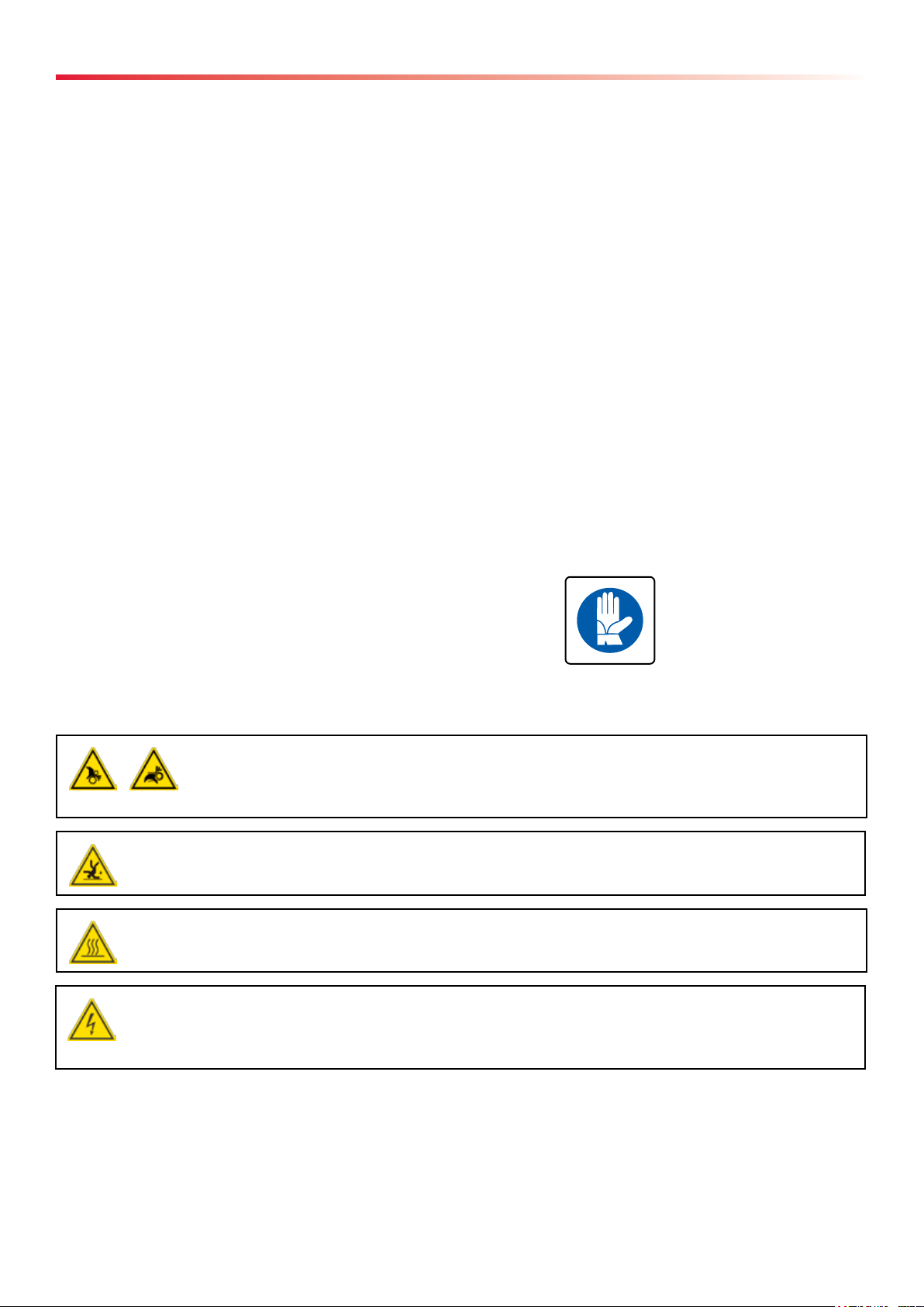
PERSONAL PROTECTIVE EQUIPMENT (PPE)
The device bears an adhesive label reminding you of the obligation:
- to use gloves
RESIDUAL RISKS
You must pay attention to the following residual risks present when using PowerSeat:
WARNING! ROTATING PARTS TRAPPING RISK
Always wear clothing and protective gloves that are form tting. Avoid loose gloves or
clothing and always follow the instructions in the manual.
WARNING! RISK OF FALLING
Always use personal protective equipment and always follow the instructions of the manual.
WARNING! HOT PARTS
See Notes reported in the electrical equipment description.
WARNING!
The plug of the machine / power supply must be suitable for the socket. Never modify the plug.
Conformed plugs and suitable sockets reduce risk of electric shock.
14 ENGLISH 01-30-14
Page 15
SAFETY INFORMATIONS
WARNING!
Do not use the electric cable for other purpose then those intended, and in particular do not use the
cable to carry or suspend the device, or to disconnect the plug. Do not go near the cable to heat
sources, oil, sharp edges or moving parts of the machine.
Damaged or tangled cables increase risk of electrical shock.
WARNING!
Do not use the device with faulty switches.
Devices or control systems with faulty switch are dangerous and require maintanance.
WARNING!
Do not remove the motor carter.
Safety Precautions
01-30-14 ENGLISH 15
Page 16
Power Supply Informations
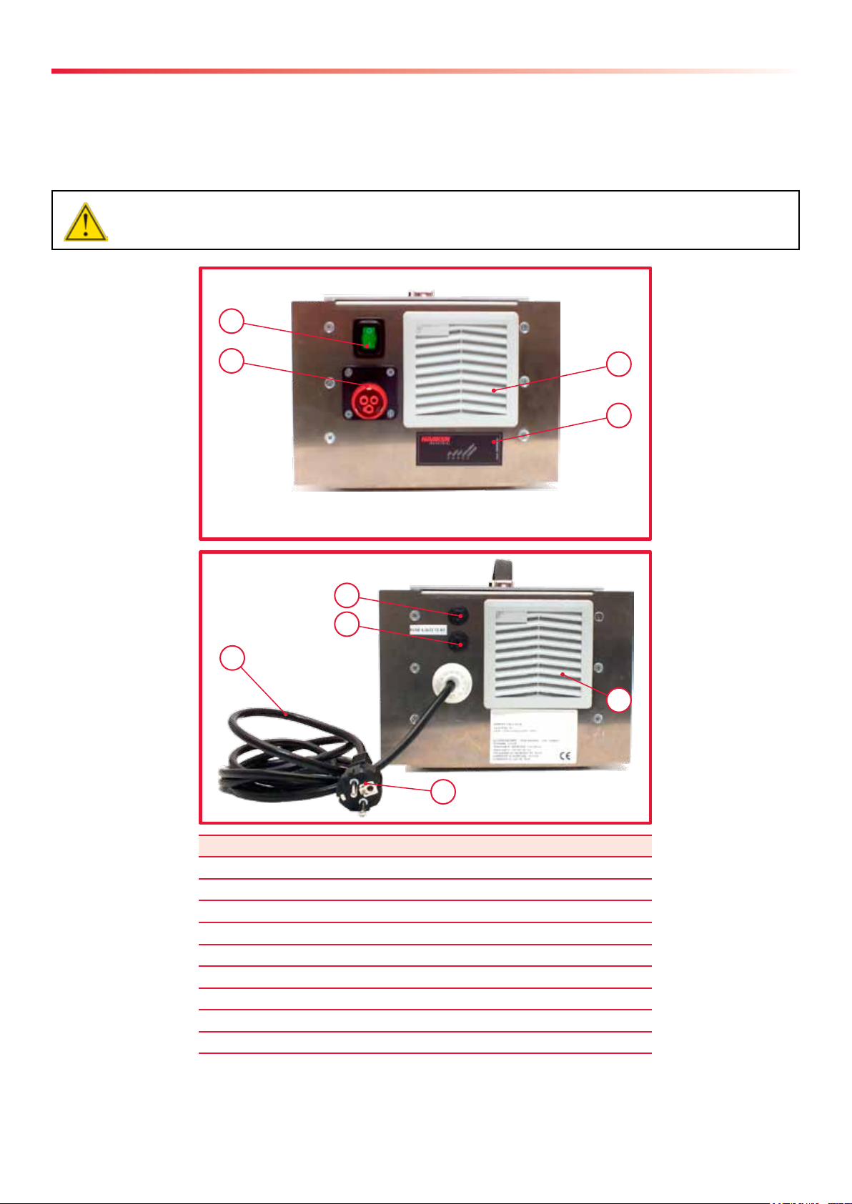
POWER SUPPLY DESCRIPTION - GENERAL
The PowerSeat Power Supply is an electronic unit specifically designed to supply only the PowerSeat electric
motor.
Power Supply convert the AC voltage (110 - 230VAC, 50/60 Hz) into 48VDC voltage and powers the motor.
WARNING!
Do not use the Power Supply of the PowerSeat to power other electric products.
1
2
8
9
5
4
3
7
6
Pos. Description
1 0/1 Switch
2 48 Vdc Socket
3 Light Interface
4 Frontal Cooling Grid
5 Electric Cable
6 Plug
7 Back Cooling Grid
8 Fuse
9 Fuse
16 ENGLISH 01-30-14
Page 17
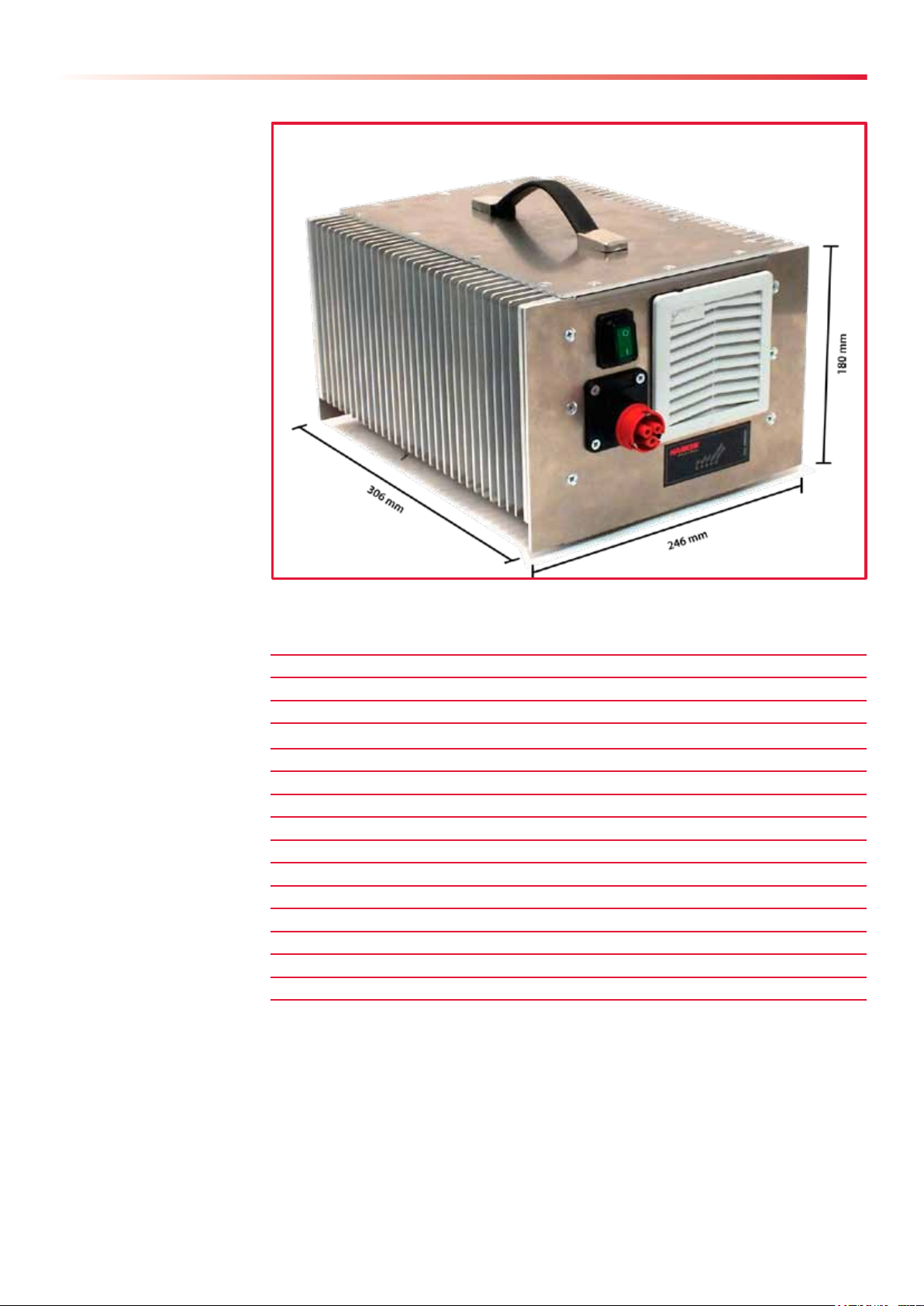
POWER SUPPLY DESCRIPTION - DIMENSION
Power Supply Informations
POWER SUPPLY DESCRIPTION - TECHNICAL DATA
Dimensions 246x306x180 mm (LxPxH)
Weight 8,5 kg
Supply Voltage 110-230 Vac
Frequency 50/60 Hz
Cable Schuko Tipo 16 A, 230 Vac
Max Output Voltage 54 Vdc
Max Output Current 25 A
Max Power 1200 W
Fuse 20 A T
Overloading Protection Electronic Control
Overtemperature Protection Electronic Control
Ingress Protection Rating IP54
Operating Environment Temperature 0° C - 40° C
Max non-condensing Humidity 85%
Working Conditions Internal or External Use
01-30-14 ENGLISH 17
Page 18

Power Supply Informations
POWER SUPPLY DESCRIPTION - LIGHT INTERFACE
"0/I" switch turn on and turn off Power Supply. The LED Interface, placed on the front side, provides indication
on the operating status of the supply using 5 LED alarms.
Alarm Description
Line It shows that there is electrical power on the supply cards.
It turns on few seconds after the switch has been activated "0/I" and it indicates that voltage inside the power supply are correct,
and the power supply will be soon usable.
Ready It shows that the power supply is providing voltage accross output connectors.
It turns on to indicate precharge voltage reaches a suitable value of the power supply power stages, when this LED is on it is possible to take energy from the power supply output.
Fault Indicates a serious fault of the power supply or a load anomaly.
Normally off, the lighting of this led indicates a very serious failure of the power supply and is necessarily an extraordinary maintenance.
Overcurrent Indicates an overload connected to the output of the power supply.
Normally off, this led illuminates to indicate that there is an overload connected at the output of the power supply.
The LED may light up for short periods at the begining of the use, this is a normal function and should not create suspected mal-
function of the power supply to the load.
Overtemp Indicates that the temperature inside the power supply or heatsink is too high.
Normally off, the ignition of this LED indicates that the power supply's internal temperature is close to 70° C. When this LED
turns on the power supply turns off not providing tension to the load, until temperature drops below 50° C.
SAFETY INFORMATIONS
WARNING!
Do not use the Power Supply in potentially ammable or explosive zone. The Power Supply can
reach high temperature when exposed to sunlight.
WARNING!
Use the Power Supply according to environmental specications! An improper use can damage
electronic circuits.
WARNING!
In use the Power Supply can reach high temperatures, around 50°/60° C. Pay attention to place it
away from objects that can be damaged!
18 ENGLISH 01-30-14
Page 19

Power Supply Informations
WARNING!
Before connecting the Power Supply to the AC voltage make sure that voltage is within the range
specied in the Power Supply technical data.
WARNING!
Do not open Power Supply cover and do not modify the power supply.
USING THE POWER SUPPLY
The PowerSeat Power Supply can be used in indoor and outdoor environments.
Place the Power Supply away from any heat sources. Keep a clean area around the Power Supply, not less
than 50 mm on all sides, to ensure a sufficient ventilation for cooling.
It is recommended, whenever possible, do not expose the Power Supply to direct sunlights, and do not place it
in humid environments.
To turn on and turn off use the switch on the frontal panel.
Position " I " - in addition to the light in the switch itself, which indidates the presence of main AC voltage,
after few seconds it turns on the "Line" light. To obtain voltage accross output connectors it needs to wait a
few seconds more, when "Ready" green light will turn on.
Position " 0 " - the Power Supply turns off immediately, no Wa.
CLEANING THE POWER SUPPLY
The Power Supply can be cleaned with a wet rag with alcool or detergent. Do not use solvent or aggressive
detergent, they can have chimical reactions with alumium Power Supply container, damage connection plastic
parts and the LEDs. Do not spray or pour any liquid on the Power Supply if it is powered.
Periodically remove and replace ventilation filters (it depends on using environment).
Using the Power Supply in a dusty environment, frequently remove dust inside the channels of ventilation,
accurately remove the dust with dry compressed air or with a brush.
WARNING!
Before cleaning the Power Supply turn off it and disconnect all cables.
WARNING!
Before using the Power Supply make sure that all connection cables and the Power Supply itself are
completely dry, to minimize the risk of electric shock.
01-30-14 ENGLISH 19
Page 20

PowerSeat PWRS-E
DEVICE DESCRIPTION - GENERAL
The PowerSeat is designed to help qualified operators ascend a rope and descend using a passive manual
device.
The rope must be inserted in its housing in the vertical tube, through the deflector sheave, wrapped round the
winch drum and locked in the rope grab.
When the engine is started, a transmission system rotates the drum and creates a traction force on the rope.
Electrical motor supplies power during the ascent, start and stop is an electrical system and the control system
is provvided with an anti-panic system and an emergency button.
During descent the engine is switched off and the operator uses the lever to open the rope grab and allow the
rope to slide round the drum in a controlled descent.
17
16
1
2
3
25
4
6
5
7
8 9 11 12
Pos. Description
1 Seat
2 Snap-hook
3 Strop
4 Knob
5 Cover
6 Rope grab
7 Stripper arm
8 Winch Drum
9 Reduction gear casing
10 Clamp
11 Damper
12 Anchorage point
13 Front plate
19
20
10
13
21
14
23
Pos. Description
14 Motor Cover
15 Protection
16 Front tube
17 Eyebolt
18 Pin
19 Emergency button
20 Accelerator lever
21 Accelerator control
22 Frame
23 Power cable
24 Cable anchorage eyebolt
25 Control lever
18
15
22
24
20 ENGLISH 01-30-14
Page 21

DEVICE DESCRIPTION - DIMENSIONS
PowerSeat PWRS-E
01-30-14 ENGLISH 21
Page 22

PowerSeat PWRS-E
DEVICE DESCRIPTION - SAFE WORKING LOAD
The Safe Working Load of the PowerSeat is 300 Kg (661,4 lb).
WARNING!
Do not apply a load greater than the Safe Working Load to the PowerSeat.
DEVICE DESCRIPTION - ROPE REQUIREMENTS
WARNING!
Use only EN1891 certied ropes with a diameter of between 10 - 12.7 mm (3/8" - 1/2").
WARNING!
Use only ropes in good condition.
WARNING!
For correct maintenance of ropes consult the rope Usage Manual.
DEVICE DESCRIPTION - VIBRATIONS
Vibration values measured are below the limits set by the reference standards:
Hand-arm <2,5 (A(8)m/s), Whole body <0,5 (A(8)m/s).
DEVICE DESCRIPTION - NOISE EMISSION
The values of the measured noise emissions are below the limits allowed under the applicable standards - ISO 3746:
- Average surface acoustic pressure level weighted A:
(L
- Acoustic power level weighted A (L
(medio)) < 80 dB(A)
pfA,d
) < 90 dB(A)
WA
22 ENGLISH 01-30-14
Page 23

PowerSeat PWRS-E
DEVICE DESCRIPTION - TECHNICAL DATA
Below are the principal technical data of the PowerSeat obtained with a rope 11mm (7/16") in diameter at a
temperature of 20°C at sea level.
Rope Semi static 10mm-12.7mm (1/8"-1/2") EN1891 rope
Safe working load 300 kg (661,4 lb)
Maximum Load on Seat 150 kg (330,7 lb)
Ascent speed 110 V 13 m/min (120 kg) (42.7 ft/min (264,5 lb))
8,5 m/min (300 kg) (27,9 ft/min(661,4 lb))
Ascent speed 230 V 13 m/min (120 kg) (42.7 ft/min (264,5 lb))
10 m/min (300 kg) (27,9 ft/min(661,4 lb))
Reduction Ratio 48,6:1
Device Weight 19 kg (41,9 lb)
Dimensions 815 x 538 x 326 mm (32,1" x 21,2" x 12,8")
Recommended working temperature range 0°C +40°C
Ingress Protection Rating IP 54
DEVICE ESCRIPTION - MOTOR
Motor Brushless electric
Nominal Voltage 48 Vdc
Net Power 0,8 kW
Thermal Protection Activation temp. 100°C (212°F)
Continuous operation distance suggested 780 m (120 kg (264,5 lb))
100 m (300 kg (661,4 lb))
USING THE DEVICE - CHECKING THE DEVICE BEFORE USE
Before and after every use, visually inspect the PowerSeat for traces of wear, damage or breakage. If such traces are
present, do not use the device. If the worn or defective parts are not immediately replaced, the manufacturer will
assume no responsibility for resulting damage or accidents.
In particular:
Check that the strop and carabiner are
Check the movement of the rope grab cover.
intact.
01-30-14 ENGLISH 23
Page 24

PowerSeat PWRS-E
Check that the rope grab knob is working by
rotating the control lever and releasing it
(CLOSE JAW).
Check that the rope grab knob is working by
rotating the cotrol lever and releasing it
(OPEN JAW).
Inspect all screws and check that the marker on the screws and on the plate are aligned.
In case of any misaligned contact a HARKEN service center.
Ispect the lever control screw, and all screws
that secure the seat to the frame and check
that they are properly tightened.
24 ENGLISH 01-30-14
Rotate the winch drum clockwise by hand
and make sure that it cannot rotate
anticlockwise.
Page 25

PowerSeat PWRS-E
Verify the functionallity of the emergency
button, pushing the emergency button and
verifying the stop of the device.
Rotate clockwise the emergency button to
rearm the device.
Verify the functionallity of the anti-panic
system:
push the accelerator lever to start the
device, and push further the accelerator
lever up to the stop, and verify the stop of
the device.
Release the accelerator lever to disarm the
anti-panic system.
NOTE!
Before every use carry out a function check with the device unloaded to check for any problems
with the engine.
USING THE DEVICE - ADJUSTING THE ACCELERATOR CONTROL POSITION
Before using the device verify the position of the accelerator control so that it is ergonomically comfortable for
the operator, depending on the use that is expected.
1. Untight the first screw of the accelerator
control using an hex key n°4.
01-30-14 ENGLISH 25
2. Completely untight the second screw of the
accelerator control using an hex key n°4, pay
attention to not lose the self-locking nut.
Page 26

PowerSeat PWRS-E
3. Slide out the accelerator control from the
support.
NOTE!
Pay attention not to pass
the accelerator control's
cable outside of the
devise frame.
4. Change position to the support and replace
the accelerator control.
6. Tighten the support's screws.
USING THE DEVICE - ADJUSTING THE CONTROL LEVER POSITION
Before using the device it is possible set up the position of the control lever so that it is ergonomically
comfortable for the operator, depending on the use that is expected.
1. Loose the control lever screw using an
hex key n°5.
26 ENGLISH 01-30-14
2. Place the control lever on one of 3 possible position.
Page 27

sible position.
PowerSeat PWRS-E
3. Tighten the control lever screw.2. Place the control lever on one of 3 pos-
USING THE DEVICE - PRIMARY ROPE INSTALLATION PROCEDURE
1. Place the PowerSeat on the ground.
2. Pull open the clamp and slide the front
tube into the housing.
WARNING!
Slide the front tube correctly into its housing until the red reference mark is no longer visible.
01-30-14 ENGLISH 27
Page 28

PowerSeat PWRS-E
3. Pass the rope inside the pin. 4. Fit the rope into the front tube.
5. Pass the rope round the pulley. 6. Make sure the rope has been fitted correctly
into its housing.
7. Wind the rope clockwise around the winch
drum.
8. Pass the rope over the stripper arm.
WARNING!
Take at least two turns of the rope around the winch drum, and if it slips under load increase the
number of turns to a maximum of four, taking care not to overlap the rope.
28 ENGLISH 01-30-14
Page 29

PowerSeat PWRS-E
NOTE!
The number of turns needed round the winch drum depends on the load and the condition of the
rope.
Check the device's descending capacity in its working conguration.
Before use ascend with the device, no more than 1 mtr (3,28 ft) and check, according to the descent procedure 1, that it's descending smoothly.
In case of difculties unwind the rope, and reduce the turns to not less than 2 wraps, until you have
the optimal conguration.
9. Fit the rope into the rope grab. Raise the
cover to make this easier.
11. Close the protective cover with the strap.
10. Position the rope inside the stopper.
01-30-14 ENGLISH 29
Page 30

PowerSeat PWRS-E
USING THE DEVICE - WIRING THE POWER SUPPLY SYSTEM
WARNING!
Before wiring the Power Supply to the device completely unroll the power cable to allow a device
proper use, and verify the integrity of the cable and its connectors.
01. Connect the power cable to the device
socket.
03. Connect the 48V power cable to the Power
Supply.
02. Fasten the cable snap-hook to the cable
anchorage eyebolt.
04. Connect the Power Supply plug to the
110/230V power line.
05. Turn on the Power Supply pressing the
"0/I" switch. For voltage will need to wait a few
seconds until the first two LED alarms are both
lighting.
30 ENGLISH 01-30-14
06. Verify that the Power Supply systemis
working checking the LED alarms Line and
Ready are lighting and try to operate the
device.
Page 31

PowerSeat PWRS-E
USING THE DEVICE - PREPARING TO ASCEND
Install two ropes, Primary and Secondary, with separate anchorage points. Each rope must support at least 15
kN.
Install the Primary (or working) rope on the device as directed "Primary Rope Installation Procedure"
paragraph.
Attach the Secondary (or backup) rope is attached to the operator using a fall arrest device (EN353/2
approved) and energy absorber (EN355 approved).
Both ropes must be EN1891 Class A certified and have a diameter of between 10 (1/8" ) and 12.7 mm (1/2").
In the case of fault or breakage of the device or of the primary rope, the load will be immediately transferred
to the secondary rope through the fall arrest device, thus constituting the anti-fall system.
WARNING!
Use the PowerSeat only with the primary and secondary ropes installed so as to create the anti-fall
system described above.
To use the PowerSeat the operator must also wear:
1. A full EN 361 and EN813 certified harness to which the device is attached at the lower front attachment and
the fall arrest device at the upper front attachment
2. An EN 795 B certified waist strop connected to the two side attachments of the harness and passing
outside the front tube of the PowerSeat
3. Appropriate Individual Personal Protective Equipment (PPE) (e.g. helmet, gloves and protective glasses)
4. Suitable clothing, form fitting so it cannot catch on moving parts
1
9
10
4
7
8
3
2
6
11
Pos. Description
1 Primary Rope
2 Secondary Rope
3 Fall Arrest Device
4 Upper Front Attachment
5 Full Harness
6 Waist Strop
7 Lower Front Attachment
8 Side Attachment Points
9 Helmet
10 Protective Glasses
11 Gloves
WARNING!
Do not use the PowerSeat in the case of illness, tiredness or if under the inuence of drugs or
alcohol.
01-30-14 ENGLISH 31
Page 32

PowerSeat PWRS-E
WARNING!
Keep your hands, feet and clothing etc away from the moving parts of the device.
WARNING!
During the ascent the motor cover could become hot. Handle the device with care to avoid injury.
WARNING!
During the use of the device any knots on the rope, if they are involved in the device circuit, may
damage the device and cause dangerous conditions.
NOTE!
Before using the PowerSeat make sure that the power cable length is greater than the distance
between the Power Supply and the higher ascenting point of the device.
USING THE DEVICE - ASCENT PROCEDURE 1
Pos. Description
1
2
3
4
5
1 Fall Arrest Device
2 Upper Front Attachment
3 Lower Front Attachment
4 Waist Strop
5 Side Attachment Points
1. Install the primary rope on the device as indicated in the "Primary Rope Installation Procedure" paragraph.
2. Wire the power supply system as described in the "Wiring the Power Supply System" paragraph.
3. Supply voltage to the motor by turning on the 48V Power Supply.
4. Sit on the device.
5. Connect the fall arrest device to the harness as described in the “Preparing to Ascend” paragraph.
32 ENGLISH 01-30-14
Page 33

PowerSeat PWRS-E
6. Connect the waist strop to the two side attachment points of the harness, passing it outside the front tube
of the PowerSeat.
7. Connect the snap-hook provided with the device to the lower front attachment point of the harness.
8. Adjust the position of the accelerator
control so it is ergonomically comfortable for
the operator.
9. To ascent, push the accelerator lever to the
first detent.
WARNING!
Before using the device check that the rope is correctly installed.
WARNING!
Before using the device test the functionallity of the emergency button and the anti-panic system.
01-30-14 ENGLISH 33
Page 34

PowerSeat PWRS-E
USING THE DEVICE - ASCENT PROCEDURE 2
1. Install the primary rope on the device as indicated in the “Primary Rope Installation Procedure” paragraph.
2. Wire the Power Supply system as described in the "Wiring the Power Supply System" paragraph.
3. Adjust the position of the accelerator control so it is ergonomically comfortable for the operator as
indicated in the "Adjusting the Accelerator Control Position" paragraph.
4. Supply voltage to the motor by turning on the 48V Power Supply.
5. Operate the device and position it at the height of the operator’s shoulders.
6. Connect the fall arrest device to the harness as described in the “Preparing to Ascent” paragraph.
Lower Front
Attachment
to PowerSeat
Upper front
Attachment
to Fall Arrest
7. Connect the snap-hook supplied with the device to the lower front attachment point of the harness.
In ascent procedure 2 the Waist strop is not used
8. To ascent, push the accelerator lever to the first detent.
WARNING!
Before using the device check that the rope is correctly installed.
WARNING!
Before using the device test the functionallity of the emergency button and the anti-panic system.
34 ENGLISH 01-30-14
Page 35

USING THE DEVICE - USING POWERSEAT WITH A FIXED POINT
NOTE!
To use the PowerSeat with a xed point at least two operators are necessary. One operates the
device and the second is connected by the primary rope to the device and to the secondary rope by
the (EN353/2 approved) fall arrest device. Both ropes must be EN1891 certied and have a diameter
of between 10 (1/8") and 12.7 mm (1/2"). The secondary rope must have an anchorage point that
supports at least 15kN. The device is connected to a xed anchorage point on the ground which
must support at least 15kN.
PowerSeat PWRS-E
1. Pull the clamp and slide out the front tube.
3. Remove the seat.
2. Unscrew the four screws that fix the seat to
the chassis with a n°5 hex key.
4. Adjust the position of the accelerator control so it is ergonomically comfortable for the operator as
indicated in the "Adjusting the Accelerator Control Position" paragraph.
5. Place the control lever position following the "Adjusting the Control Lever Position" paragraph.
6. Install the primary rope on the device as indicated in the “Primary rope installation procedure” paragraph.
In this case the primary rope will be used to lift the second operator.
7. Wire the Power Supply system as described in the "Wiring the Power Supply System" paragraph.
8. Connect the anchorage point on the front plate of the device with the fixed anchorage point on the ground.
9. Supply voltage to the motor by turning on the 48V Power Supply.
10. To ascent, push the accelerator lever to the first detent.
01-30-14 ENGLISH 35
Page 36

PowerSeat PWRS-E
NOTE!
Before using the PowerSeat places on the ground be sure that the cable or the stand of the accelerator control are not under the device chassis.
WARNING!
To use the PowerSeat in the xed point conguration the primary rope under load must leave the
winch with a lateral and frontal angle of between ± 6°.
Max Angle ±6°
Max Angle ±6°
Anchorage
Point
Anchorage Point
To the anchorage
To the anchorage
WARNING!
Before using the device check that the rope is correctly installed.
WARNING!
Before using the device test the functionallity of the emergency button and the anti-panic system.
36 ENGLISH 01-30-14
Page 37

USING THE DEVICE - DESCENT PROCEDURE 1
PowerSeat PWRS-E
1. With one hand grasp the rope leaving the
winch.
To facilitate descent, a carabiner can
be fixed to the ring on the front tube
and the primary rope passed through
it.
2. With the other hand, turn the control lever
clockwise to allow the rope to slip on the winch
drum and permit a controlled descent. To adjust
descent speed, manually control the speed at
which the rope leaves the winch by holding
rope with arm out and bringing it in towards the
winch drum.
To stop the descent, release the control lever.
NOTE!
Take care not to overbalance when getting off the seat.
Lower the PowerSeat until the operator's feet are rmly on the ground, but the unit is still suspended. Stand up and move on the seat. Now the device can be lowered to the ground and released
from the rope.
01-30-14 ENGLISH 37
Page 38

PowerSeat PWRS-E
USING THE DEVICE - DESCENT PROCEDURE 2
1. With one hand grasp the rope leaving the
winch.
2. With the other hand, turn the control
lever clockwise to allow the rope to slip on
the winch drum and permit a controlled
descent. To adjust descent speed, manually
control the speed at which the rope leaves
the winch. To stop the descent, release the
control lever.
USING THE DEVICE - FIXED ANCHORAGE DESCENT PROCEDURE
1. With one hand grasp the rope leaving the winch.
2. With the other hand, turn the control lever clockwise to allow the rope to slip on the winch drum and permit
a controlled descent. To adjust descent speed, manually control the speed at which the rope leaves the winch.
To stop the descent, release the control lever.
USING THE DEVICE - TRANSPORT AND STORAGE
Transport the device using the box provvided at time of purchase. To transport the device disconnect the
Power Supply system. When not in use the device must be stored in its box in order to protect it from knocks
and shock. Protect the device from humidity and temperature range. The temperature required for storage
must be in the range -25°C/+55°C, and for periods not exeeding 24 hours the maximum temperature can
reach +70°C. The humidity is not expected to exeed 80%. Do not allow the device to come into contact with
corrosive substances. Clean the device before storing.
38 ENGLISH 01-30-14
Page 39

PowerSeat PWRS-E.Compact
DESCRIPTION OF COMPACT VERSION - GENERAL
The PowerSeat Compact version maintains every device key features described in the "Device Description"
paragraph.
This device version is designed to optimize the qualified operator's work when he works without seat or using
the device with a fixed anchorage.
1
2
10
4
5
6
7
8 9 11 12
Pos. Description
1 Short Tube
2 Front Plate
3 Control Lever
4 Knob
5 Cover
6 Rope Grab
7 Stripper Arm
8 Winch Drum
9 Reduction Gear Casing
10 Clamp
11 Damper
16
17
15
14
20
18
13
Pos. Description
12 Anchorage Point
13 Snap-hook
14 Strop
15 Motor Cover
16 Emergency Button
17 Accelerator Lever
18 Accelerator Control
19 Frame
20 Power Cable
21 Cable anchorage eyebolt
3
19
21
01-30-14 ENGLISH 39
Page 40

PowerSeat PWRS-E.Compact
DESCRIPTION OF COMPACT VERSION - DIMENSIONS
40 ENGLISH 01-30-14
Page 41

PowerSeat PWRS-E.Compact
USING THE COMPACT VERSION DEVICE - CHECKING THE COMPACT VERSION DEVICE BEFORE USE
Before and after using the PowerSeat Compact version follow the procedure described in the "Checking the Device
Before Use" paragraph.
USING THE COMPACT VERSION DEVICE - PRIMARY ROPE INSTALLATION PROCEDURE ON COMPACT VERSION
1. Place the PowerSeat on the ground. 2. Pull open the clamp and slide the short tube
into the housing.
WARNING!
Slide the front tube correctly into its housing until the red reference mark is no longer visible.
3. Remove the strop from upper anchorage
point.
01-30-14 ENGLISH 41
4. Fasten the strop on the lower anchorage
point.
Page 42

PowerSeat PWRS-E.Compact
5. Pass the primary rope inside the pins.
7. Make sure the rope has been fitted correctly
into its housing.
6. Pass the rope round the pulley.
8. Wind the rope clockwise around the winch
drum.
WARNING!
Take at least two turns of the rope around the winch drum, and if it slips under load increase the
number of turns to a maximum of four, taking care not to overlap the rope.
NOTE!
The number of turns needed round the winch drum depends on the load and the condition of the
rope.
Check the device's descending capacity in its working conguration.
Before use ascend with the device, no more than 1 mtr (3,28 ft) and check, according to the descent procedure 1, that it's descending smoothly.
In case of difculties unwind the rope, and reduce the turns to not less than 2 wraps, until you have
the optimal conguration.
42 ENGLISH 01-30-14
Page 43

PowerSeat PWRS-E.Compact
9. Pass the rope over the stripper arm.
10. Position the rope inside the stopper.
10. Fit the rope into the rope grab. Raise the
cover to make this easier.
USING THE COMPACT VERSION DEVICE - PREPARING TO ASCENT WITH THE COMPACT VERSION
To use the PowerSeat Compact version follow the procedure described in "Preparing to Ascent" paragraph.
WARNING!
Leggere attentamente il paragrafo "Procedura di preparazione alla risalita" prima di utilizzare la macchina.
USING THE COMPACT VERSION DEVICE - ASCENT PROCEDURE WITH THE COMPACT VERSION
1. Install the primary rope following "Primary Rope Installation Procedure on Compact version" paragraph.
2. Wire the power supply system as described in the "Wiring the Power Supply System" paragraph.
3. Adjust the position of the accelerator control so it is ergonomically comfortable for the operator as
indicated in the "Adjusting the Accelerator Control Position" paragraph.
4. Supply voltage to the motor by turning on the 48V Power Supply.
5. Operate the device and position it at the height of the operator’s shoulders.
6. Connect the fall arrest device to the harness as described in the “Preparing to Ascent” paragraph.
01-30-14 ENGLISH 43
Page 44

PowerSeat PWRS-E.Compact
7. Connect the snap-hook supplied with the device to the lower front attachment point of the harness.
Fall Arrest
Device
Lower Front
Attachment to
PowerSea
In ascent procedure 2 the Waist strop is not used
8. To ascent, push the accelerator lever to the first detent.
WARNING!
Before using the device check that the rope is correctly installed.
WARNING!
Before using the device test the functionallity of the emergency button and the anti-panic system.
USING THE COMPACT VERSION DEVICE - USING COMPACT VERSION POWERSEAT WITH A FIXED ANCHORAGE
NOTE!
To use the PowerSeat with a xed point at least two operators are necessary. One operates the
device and the second is connected by the primary rope to the device and to the secondary rope by
the (EN353/2 approved) fall arrest device. Both ropes must be EN1891 certied and have a diameter
of between 10 (1/8") and 12.7 mm (1/2"). The secondary rope must have an anchorage point that
supports at least 15kN. The device is connected to a xed anchorage point on the ground which
must support at least 15kN.
1. Adjust the position of the accelerator control so it is ergonomically comfortable for the operator as
indicated in the "Adjusting the Accelerator Control Position" paragraph.
2. Set the control lever position following the "Adjusting the Control Lever Position" paragraph.
3. Install the primary rope on the device as indicated in the “Primary rope installation procedure on Comapct
version” paragraph. In this case the primary rope will be used to lift the second operator.
4. Wire the power supply system as described in the "Wiring the Power Supply System" paragraph.
44 ENGLISH 01-30-14
Page 45

PowerSeat PWRS-E.Compact
5. Connect the anchorage point on the front plate of the device with the fixed anchorage point on the ground.
6. Supply voltage to the motor by turning on the 48V Power Supply.
7. To ascent, push the accelerator lever to the first detent.
NOTE!
Before using the PowerSeat places on the ground be sure that the cable or the stand of the accelerator control are not under the device chassis.
WARNING!
To use the PowerSeat in the xed point conguration the primary rope under load must leave the
winch with a lateral and frontal angle of between ± 6°.
Max Angle ±6°
Max Angle ±6°
Anchorage
Point
Anchorage Point
To the anchorage
To the anchorage
WARNING!
Before using the device check that the rope is correctly installed.
WARNING!
Before using the device test the functionallity of the emergency button and the anti-panic system.
01-30-14 ENGLISH 45
Page 46

PowerSeat PWRS-E.Compact
USING THE COMPACT VERSION DEVICE - DESCENT PROCEDURE WITH THE COMPACT VERSION
1. With one hand grasp the rope leaving the
winch.
2. With the other hand, turn the control
lever clockwise to allow the rope to slip on
the winch drum and permit a controlled
descent. To adjust descent speed, manually
control the speed at which the rope leaves
the winch. To stop the descent, release the
control lever.
USING THE COMPACT VERSION DEVICE - FIXED ANCHORAGE DESCENT PROCEDURE WITH THE COMPACT VERSION
1. With one hand grasp the rope leaving the winch.
2. With the other hand, turn the control lever clockwise to allow the rope to slip on the winch drum and permit
a controlled descent. To adjust descent speed, manually control the speed at which the rope leaves the winch.
To stop the descent, release the control lever.
USING THE COMPACT VERSION DEVICE - CONVERTING THE POWERSEAT PWRS-G IN THE COMPACT VERSION
To obtain the Compact version from PowerSeat PWRS-G it is required to buy the short tube and follow the
procedure described below:
1. Pull open the clamp and slide out the front
tube.
46 ENGLISH 01-30-14
2. Unscrew the four screws that fix the seat to
the chassis with a n°5 hex key.
Page 47

PowerSeat PWRS-E.Compact
3. Remove the seat. 4. Pull open the clamp and slide the short tube
into the housing.
WARNING!
Slide the front tube correctly into its housing until the red reference mark is no longer visible.
5. Remove the strop from upper anchorage
point.
6. Fasten the strop on the lower anchorage
point.
01-30-14 ENGLISH 47
Page 48

Maintenance
CLEANING
Regularly clean and dry the device with a damp cloth to remove accumulated dirt. Do not use a direct jet of
water or a high pressure water jet cleaner. Do not use degreasing products, solvents or abrasive pastes.
MAINTENANCE
Before and after every use visually inspect the PowerSeat for traces of wear, damage or breakage. Refer to the
“Checking the device before use” paragraph for more detail on this inspection.
Every year, once a year send the device to the manufacturer or to an authorized Harken Service Center for a
complete inspection.
The first year, the device must be sent to the manufacturer within 12 months from the date of purchase. The
non-observance of such condition invalidates the warranty of the machine.
The maintenance must be recorded in the Maintenance Schedule.
Dismantling and Disposal
When the device is dismantled, it is necessary to separate the parts in plastic, those in metal and
electrical components, which must be sent to differentiated disposal centres in accordance with
the regulations of the country where the device is dismantled.
48 ENGLISH 01-30-14
Page 49

POWERSEAT AND MOTOR
Problem Possible Causes Possible Solutions
The rope slips on the
winch drum
- too few turns around the winch drum
- take another turn of the rope round the winch
drum
Diagnosis and Fault Finding
- diameter of rope not in prescribed range
The engine does not start - incorrect engine starting procedure
- incorrect Power Supply starting procedure
- engine fault
- it is activated the motor thermal protection
Limited lifting capacity - engine malfunctioning
- overload condition
Difficult descent - too many wraps on winch drum
- rope grab system possible malfunctioning
- replace the rope
- refer to "Wiring the Power Supply System" paragraph in this User Manual
- verify that the emergency button is disarmed
- verify the integrity of the cable and its connectors
- verify that the input voltage it is in the correct
range
- refert to Power Supply "Diagnosis and Fault
Finding" paragraph
- contact Harken for more informations
- wait until the motor temperature is below the
block temperature. This operation may take several
tens of minutes.
- contact Harken Tech Service for more informations
- reduce the load
- unwind the rope, reducing wraps. Leave at least 2
wraps on winch drum
- contact Harken Tech Service for more informations
POWER SUPPLY
LED alarm Possible Causes Possible Solutions
LED "Line" off - power cable is not connected
- fuse is blown
- Power supply fault
LED "Fault" on - serious Power Supply fault - contact Harken for more informations
LED "Overcurrent" e "Fault" on- output overcurrent - remove the overcurrent condition, turn off the
LED "Overtemperature" on - incorrect Power Supply positioning
- blocked or inadeguated ventilation
- Power Supply thermal protection is activated
- check the power cable is not damaged
- verify that the plug is correctly wired
- change the fuse (6,3x32 16AT)
- if the green switch light is on contact Harken Tech
Service for more informations
Power Supply, wait 15 seconds and turn on the
Power Supply
- verify the Power Supply location and that the
space around itself is sufficient for its cooling
- verify that the power supply is far from heat
sources and not exposed to sunlights
- verify the ventilation grid cleaning and replace if
necessary
- wait that the Power Supply temperature is below
the block temperature
01-30-14 ENGLISH 49
Page 50

Maintenance Schedule
Owner name
Product name and Model
Serial Number
Engine Serial Number
Year of manufacture
Date of purchase
Date of first use
Maintenance interval Annual
Maintenance Schedule
Date of Service Description of Service
Name and Signature of
Maintanance Operator
Date of Next
Intervention
50 ENGLISH 01-30-14
Page 51

Maintenance Schedule
Date of Service Description of Service
Name and Signature of
Maintanance Operator
Date of Next
Intervention
01-30-14 ENGLISH 51
Page 52

52 ENGLISH 01-30-14
Page 53

Page 54

Manufacturer/EU Representive
Via Marco Biagi 14, 22070 Limido Comasco (CO), Italy
Harken Italy S.p.A.
Tel 031.3523511; Fax 031.3520031
Web: www.harken.it
Email: info@harken.it
Worldwide Limited Warranty
Refer to the Harken World Limited Warranty on the website at:
http://www.harkenindustrial.com/technical-information/warranty/
The product warranty is accepted only if it has been maintained as specified in this Manual by Harken authorized personnel and is
accompanied by Maintenance Schedule properly compiled
 Loading...