

Page 1
Installation and Maintenance Manual
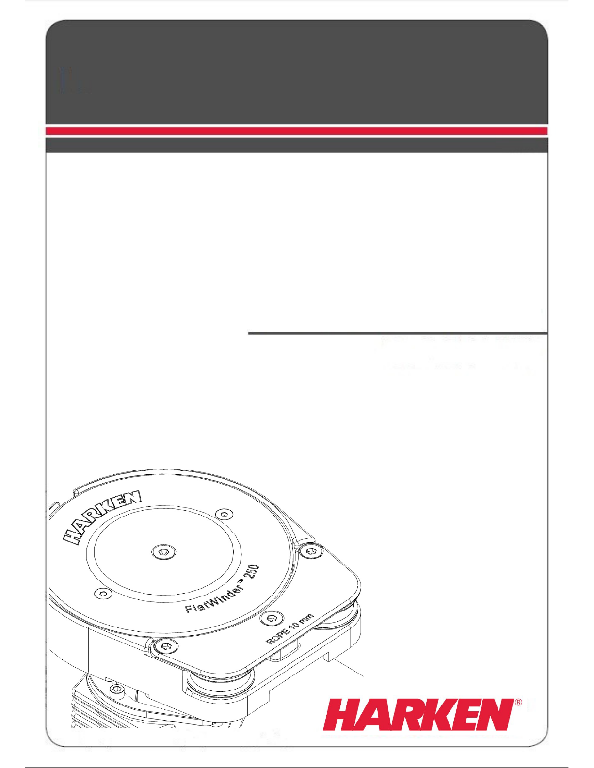
FlatWinder
250
-
500
MFW-02
TM
Page 2

FlatWinder
250
-
500
Installation and Maintenance Manual
Glossary 3
Safety Information 4
General advice 4
Introduction 5
Technical characteristics 5
Performance data 5
Weight 5
Maximum working load 5
Outline FlatWinderTM250 6
Outline FlatWinderTM500 7
Installation 8
FlatWinderTM installation procedure 9
Electric wiring diagrams 14
Rope installation 16
Maintenance 16
Washing 16
Maintenance table 16
Disassembly procedure 17
Harken® limited worldwide warranty 18
Ordering spare parts 18
Exploded view 19
FlatWinderTM 250 19
FlatWinderTM 500 21
Horizontal electric motor 12V/24V FlatWinderTM250 23
Horizontal electric motor 12V/24V FlatWinderTM500 25
TM
2
Page 3
FlatWinder
250
-
500
Installation and Maintenance Manual
Glossary
Intended use – specific and proper use of the winch for which it is designed
Improper use – use of the device in a different way from that indicated in the instructions for
use specified in this manual
Qualified operator – persons who have attended specialisation and training about the use of
the device
User – persons who use the winch regularly
Maximum working load (MWL) – maximum value of the load the winch can bear
WARNING!
DANGER!
this denotes mandatory actions by the user; without these actions, the user
is subjected to injury and the device can be seriously damaged
this denotes the existence of the potential danger, which could cause injury or
damage if the information or instructions are not followed
NOTE!
this denotes important information concerning the device
TM
3
Page 4

FlatWinder
250
-
500
Installation and Maintenance Manual
Safety Information
WARNING! Read this manual carefully and fully understood before using the system to
avoid personal injury or property damage during system operation.
• Install and use the winch only as described in the technical information supplied.
• Improper use can cause severe harms to users, equipment and the boat.
• This information is DESTINED EXCLUSIVELY for qualified operators.
• Installation of the winch by personnel who are not experts may cause serious damage
to the winch and the boat.
• Never substitute any winch part with one that is not original. Even though they look
similar and are both made by Harken®, the non-original part may not be suitable and
the warranty will be invalidated.
• Do not apply to the winch loads greater than the MWL (Maximum Working Load).
• Wear suitable clothing when using the winch, to avoid loose ends of fabric becoming
entangled in the winch.
• If the winch is powered by an electric motor:
o Make sure the power is switched off before installing or carrying out
maintenance on the winch.
• If the winch is powered by a hydraulic motor:
o Do not operate the hydraulic motor during installation or maintenance
o Do not let the oil in the system come into contact with your eyes or skin.
• Harken® cannot be responsible for damage or injury resulting from unsafe product use,
lack of maintenance or incorrect product and /or system installation or operation.
• This manual is an integral part of the device and aims to provide all the information
needed for its safe and correct use and for proper maintenance
• This manual gives technical information on winch installation and maintenance,
including disassembling and reassembling.
• Installation, disassembling and reassembling of the winch by personnel who are not
experts may cause serious damage to users and those in the proximity of the winch.
• This manual is available only in English. If you do not fully understand the English
language, do not carry out the operations described in this Manual. For any doubts,
questions or comments contact the Harken distributors nearest to you, Special Project
assistance, or contact the Harken Italy Technical Service by e-mail:
techservice@harken.it
• See www.harken.com for additional safety information.
General advice
Intended use
Harken winches are designed and manufactured for a use on sailing boats to control sheets,
halyards and related sail and rig systems. For any other usage, contact the Harken Italy
Technical Service by e-mail: techservice@harken.it
Improper use
The Harken winch must not be used for purposes different from those outlined in “Intended
use” chapter, or for purposes not mentioned in this manual or different from those mentioned.
The Harken winch must not be used if unauthorized modifications or interventions have been
carried out.
Do not use the winch for hauling, mooring the boat or weighing the anchor.
Do not take turns round the base of the winch drum.
Do not use the winch to turn a line to another winch (cross-sheeting).
TM
4
Page 5
FlatWinder
250
-
500
Installation and Maintenance Manual
Introduction
This manual gives technical information on FlatWinderTM installation and maintenance,
including disassembling and reassembling.
This information is DESTINED EXCLUSIVELY for specialised personnel or expert users.
Installation, disassembling and reassembling of the FlatWinderTM by personnel who are not
experts may cause serious damage to users and those in the vicinity of the FlatWinderTM.
Harken® accepts no responsibility for defective installation or reassembly of its FlatWinderTM.
In case of doubt the Harken® Tech Service is at your disposal at techservice@harken.it
This Manual is available only in English. If you do not fully understand the English language,
do not carry out the operations described in this Manual.
Technical characteristics
Rope diameter Ø10
Performance data
FlatWinderTM 250 FlatWinderTM 500
Voltage 12V 24V 12V 24V
max load (kg) 250 250 500 500
Line speed (m/min)** 35 35 26 32
Current absorption at max load (A) 210 140 320 160
**Line speed is measured with no load
Weight
FW250E A FW500E A
weight (kg) 12.5 22.5
A = base and pulley anodised aluminum
Maximum working load
WARNING!
The maximum working load (MWL) for the FlatWinderTM250 is 250 Kg (551 lb) and
for the FlatWinderTM500 is 500 Kg (1102 lb)
Subjecting the FlatWinderTM to loads above the maximum working load can cause
the FlatWinderTM to fail or pull off the deck suddenly and unexpectedly during high
loads causing severe injury or death.
TM
5
Page 6
FlatWinder
250
-
500
Installation and Maintenance Manual
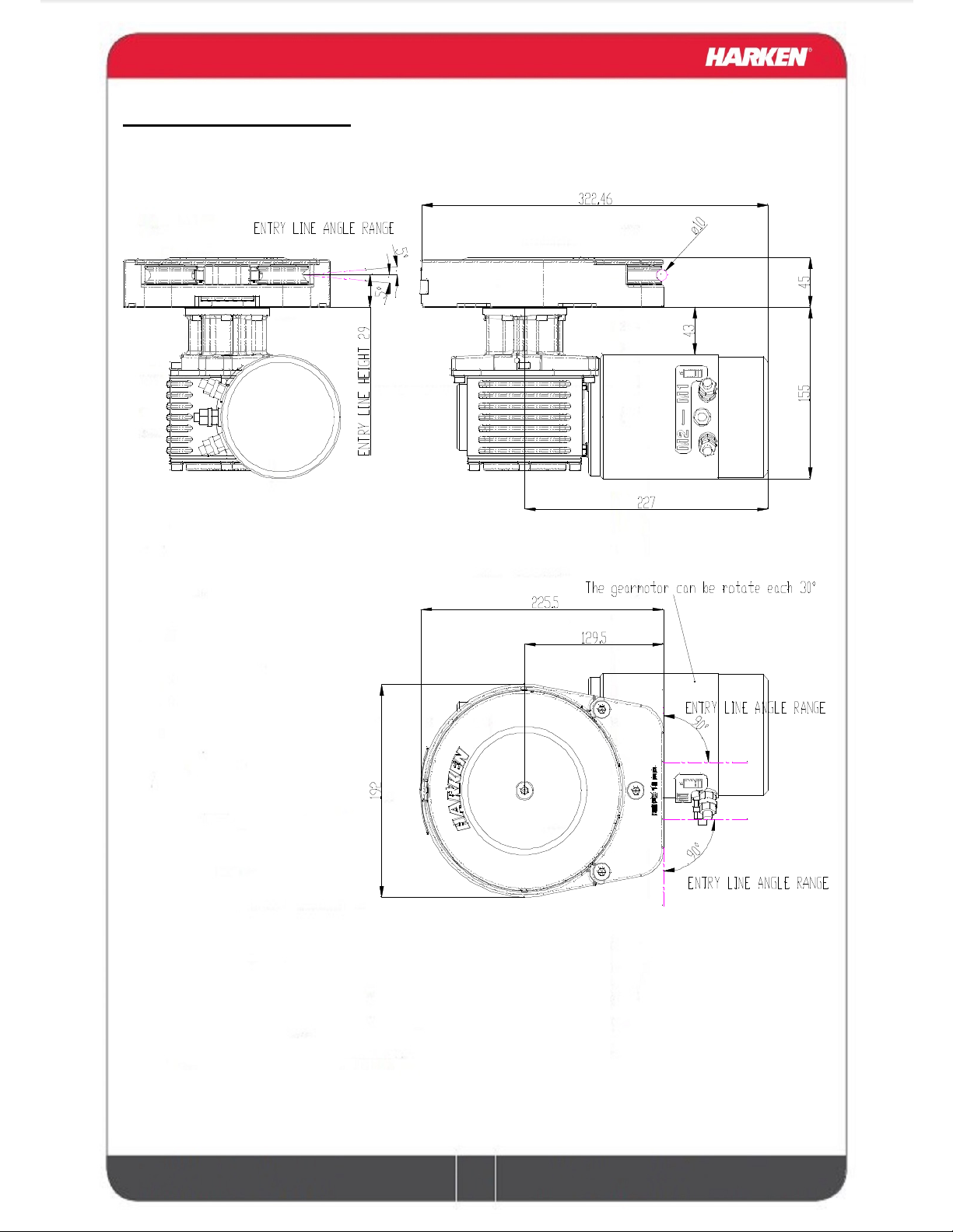
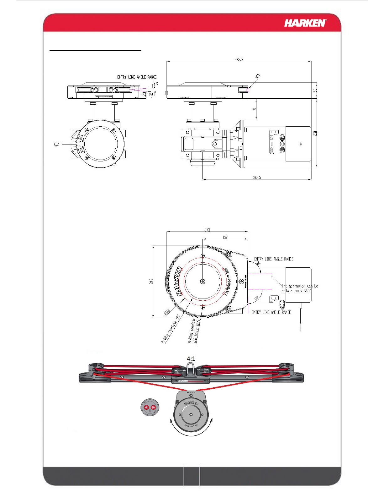
Outline FlatWinderTM250
TM
6
Page 7
FlatWinder
250
-
500
Installation and Maintenance Manual
Outline FlatWinderTM500
Typical traveler lay-out
Depending of traveler load can be used 2:1, 3:1 or 4:1 purchase
TM
7
Page 8
FlatWinder
250
-
500
Installation and Maintenance Manual
Installation
The FlatWinderTM must be installed on a flat area of the deck, reinforced if necessary to bear a
load equal to at least twice the maximum working load of the FlatWinderTM.
It is the installer's responsibility to carry out all structural tests needed to ensure that the deck
can bear the load.
Harken® does not supply the screws needed to install the FlatWinderTM since these may vary
depending on the deck on which it is to be installed.
It is the installer's responsibility to choose the correct screws taking account of the loads they
will have to bear.
Harken® assumes no responsibility for incorrect installation of its FlatWinderTM or for an
incorrect choice of mounting screws.
DANGER!
Incorrect installation of the FlatWinderTM may cause severe injury or death. Consult
the yard that built the boat in the case of doubt over the correct positioning of the
FlatWinderTM.
WARNING!
Failure to use the correct number and type of mounting fasteners or failure to ensure
the correct deck strength can result in the FlatWinderTM pulling off the deck suddenly
and unexpectedly during high loads causing severe injury or death.
WARNING!
Verify the entry angle of the sheet. This must follow the indication on the outline
drawing to avoid overrides or damaging the FlatWinderTM.
After correctly positioning the unit, check that the gearmotor, electrical components and wiring
can be housed below decks.
To help find the optimal compromise, remember that, to make the installation of the gearmotor
easier, it can be coupled to the FlatWinderTM in different positions (rotate each 30°).
Once you have decided the correct mounting position for the FlatWinderTM on the deck and
checked the space available below deck, proceed with the installation.
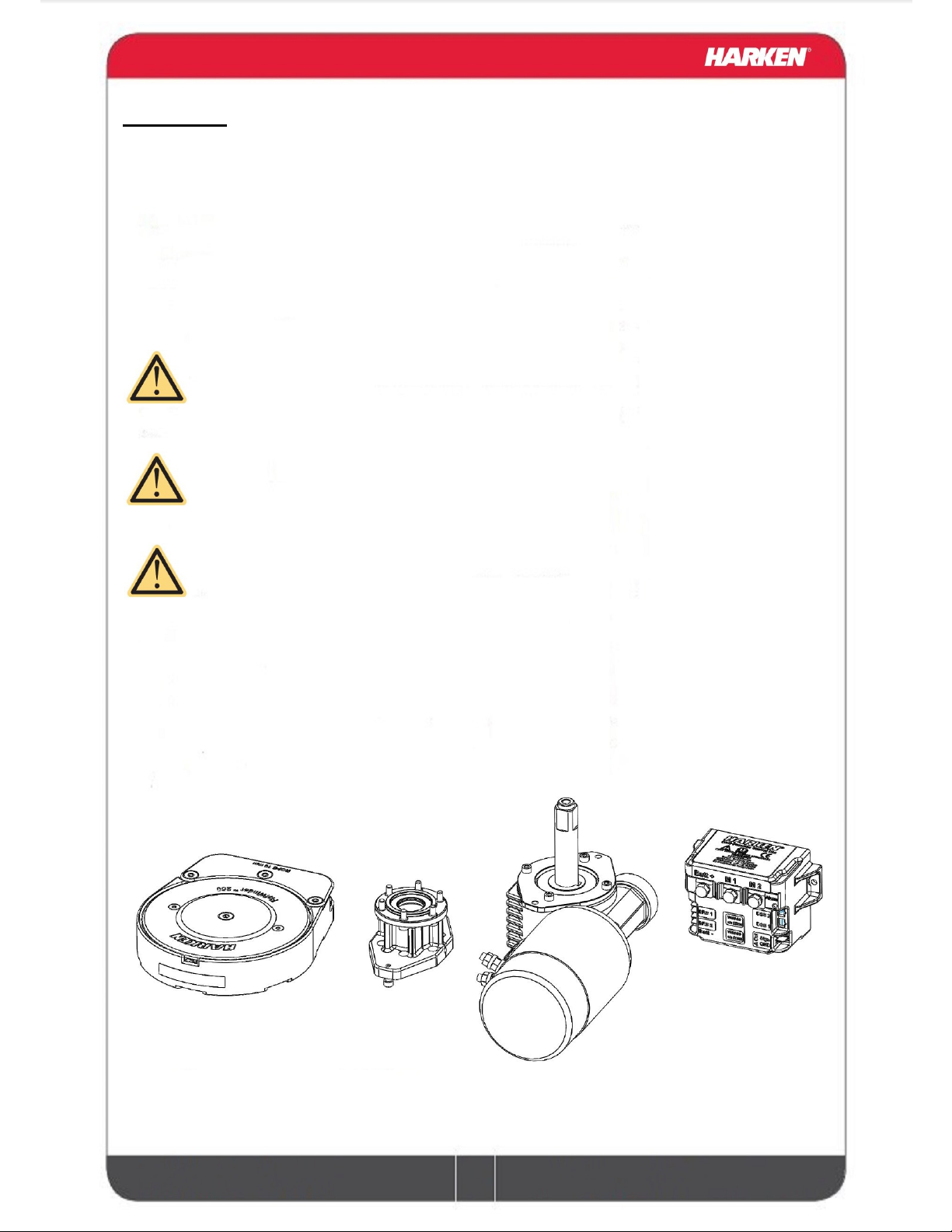
Parts included on the FatWInder
TM
250:
FlatWinderTM 250 Flange Gearmotor Dual function
TM
control box
8
Page 9
FlatWinder
250
-
500
Installation and Maintenance Manual
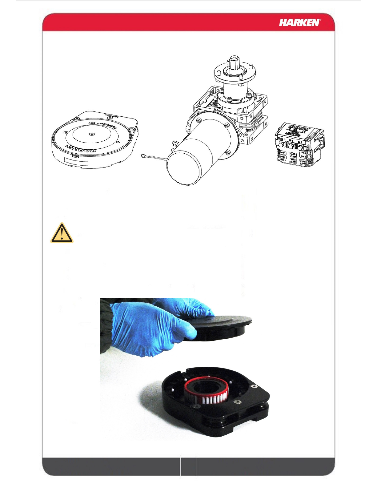
Parts included on the FatWinder
FlatWinderTM 500 Gearmotor Dual function control box
FlatWinder
TM
installation procedure
TM
500:
WARNING!
Make sure that the power is switched off before installing or carrying out
maintenance on the FlatWinderTM.
NOTICE
Before drilling the deck, check the space available below deck for the flange and the
motor
A. Remove the upper jaw (no tool require)
TM
9
Page 10

FlatWinder
250
-
500
Installation and Maintenance Manual
B. Position the base of the FlatWinderTM on the deck and mark the position of the holes or use
the drilling cut-out template at the point where you have decided to place the FlatWinderTM.
Below is a reduced scale diagram for FlatWinderTM 250.
Below is a reduced scale diagram for FlatWinderTM 500.
TM
10
Page 11

FlatWinder
250
-
500
Installation and Maintenance Manual
C. Remove the FlatWinderTM base and drill following the drilling template indication.
D. Bolt the base of the FlatWinderTM to the deck using six M6 bolts, Socket Head or Hexagonal
Headed (not supplied by Harken®), correctly chosen for the thickness and type of the boat
deck. Consult the yard that built the boat in case of doubt.
WARNING!
To install the FlatWinderTM on the deck, use only bolts in A4 stainless steel (DIN 267
part11). Bolts made of other materials may not have sufficient strength or may
corrode which can result in FlatWinderTM pulling off deck suddenly and unexpectedly
during high loads causing severe injury or death.
NOTICE
To mount FlatWinderTM on the deck, do not use countersunk bolts.
E.Fill the mounting holes and central hole with a suitable marine sealant.
F. Remove the excess adhesive/sealant from the base drainage channels and flange interface
surface
Once you have installed the base of the FlatWinderTM on the deck, proceed with motor
installation. The motor can be coupled to the FlatWinderTM in different positions. Check the
space available below deck and choose the suitable position.
TM
11
Page 12

FlatWinder
250
-
500
Installation and Maintenance Manual
Tools needed for FlatWInderTM 250:
A number five hex key
Two number thirteen wrenches
G. Position the flange H. Tighten six M6 precote screws
(8Nm/71 in-lb)
I. Position the reduction gear and motor L. Tighten the two M6 precote screws
(8Nm/71 in-lb), be sure to align the flange
Tools needed for FlatWinderTM 500:
One number seventeen, two number thirteen wrenches
I. Position the reduction gear and motor L. Tighten the four M10 screws
(20Nm/177 in-lb)
TM
12
Page 13

FlatWinder
250
-
500
Installation and Maintenance Manual
M. Insert the upper jaw, align the white balls on the lower jaw with the grooves on the upper
jaw
N. Tighten the central M8 screw (8Nm/71 in-lb)
TM
13
Page 14

FlatWinder
250
-
500
Installation and Maintenance Manual
Electric wiring diagrams
To guarantee greater efficiency in terms of safety and long life, for every FlatWinderTM model
is mandatory to install the Dual Function Control Box.
For more information, refer to the Dual Function Control Box manual.
Refer to the following diagrams for the electric wiring:
WARNING!
Read the Dual Function Control Box manual carefully before installing and using the
device.
NOTICE
For other installations, refer to the Dual Function Control Box manual.
NOTICE
In case the direction of movement is not congruent with the DSS arrow invert the
M1-M2 cable on the motor or on the Dual Function Control Box.
Fasten the Dual Function Control Box containing solenoids to bulkhead or wall: refer to the
Dual Function Control Box manual. Install remote circuit breaker between power supply and
Dual Function Control Box. Locate push-buttons on deck in a convenient spot for easy
FlatWinderTM operation: refer to the Digital System Switch manual.
TM
14
Page 15

FlatWinder
250
-
500
Installation and Maintenance Manual
Refer to the following chart for wire size:
Total distance between FlatWinderTM and battery
Current
voltage
12 V 2 32 0 50 00 70 000 95
24V 5 16 3 25 2 35 0 50
Under 16.4 ft
AWG
Under 5 m
mm2
16.4 - 32.8 ft
AWG
5 m - 10 m
mm2
32.8 - 49.2 ft
AWG
10 m - 15 m
2
mm
49.2 - 65.6 ft
AGW
NOTICE
To connect motor, attach cable terminals to
clamps between nut and lock nut. Hold nut in
contact with motor using a spanner and tighten
other nut with second spanner. Take special care
not to turn the central spindles. Be careful not to
turn central spindles. These instructions apply
when assembling and disassembling. We
recommend using a torque wrench so as to obtain
a torque equal to and no greater than 10 Nm (88
in-lb).
NOTICE
Note that correct electrical contact sequence is:
Nut – Cable Terminal – Self-Locking Washer –
Lock Nut
15m - 20 m
2
mm
TM
15
Page 16

FlatWinder
250
-
500
Installation and Maintenance Manual
Rope installation
The rope diameter should be 10mm and the cover characteristic should have high wearing
resistance.
Insert the rope between the pulley and the peeler, turn the FlatWinderTM activating the electric
motor on the proper direction.
WARNING!
Don’t insert rope bigger than 10mm or rope with splice using the previous procedure,
in case the rope have a splice should be remove the upper jaw and then engage
WARNING!
Keep far fingers or clothing when starting the engine to avoid to be entangled into
the pulley
WARNING
In case of close loop line should be check regularly the tension of the rope,
depending of temperature and humidity fiber rope can shrink a lot causing
overtension on the system
Maintenance
Washing
FlatWinderTM must be washed frequently with fresh water, and in any case after each use.
Do not allow teak cleaning products or other cleaners containing caustic solutions to come into
contact with FlatWinderTM and especially anodised, chrome plated or plastic parts.
Do not use solvents, polishes or abrasive pastes on the logos or stickers on the FlatWinderTM.
Do not use polishes or abrasive pastes on anodised, chromed plated or plastics surfaces.
Make sure that the holes and drainage channels in the base of the FlatWinderTM are not
obstructed so that water does not collect.
Maintenance table
FlatWinderTM must be visually inspected at the beginning and end of every season of sailing or
racing.
In addition they must be completely overhauled, cleaned and lubricated at least every 12
months.
After an inspection, replace worn or damaged components. Do not replace or modify any part
of the FlatWinderTM with a part that is not original.
TM
16
Page 17

FlatWinder
250
-
500
Installation and Maintenance Manual
WARNING!
Periodic maintenance must be carried out regularly. Lack of adequate maintenance
shortens the life of the FlatWinderTM, can cause serious injury and also invalidate the
FlatWinderTM warranty.
Installation and maintenance of FlatWinderTM must be carried out exclusively by
specialized personnel.
WARNING!
Make sure that the power is switched off before installing or carrying out
maintenance on the FlatWinderTM.
In the case of doubt contact Harken® Tech Service at techservice@harken.it
Disassembly procedure
Tools needed
A number four hex key
A number five hex key
Remove the central M8 screw
NOTICE
To remove the upper jaw can be used the two top holes M6 as an extractor:
Remove the two M6 countersunk screws, insert two M6x70 and tighten up the upper jaw rise.
TM
17
Page 18

FlatWinder
250
-
500
Installation and Maintenance Manual
Harken® limited worldwide warranty
The Harken winch is covered by a warranty: if during the warranty period the winch proves
defective or suffers breakages, as indicated in the warranty, the manufacturer, after checking
the device, will repair or replace the defective components.
NOTE!
Modifications carried out by the user, without explicit written authorization from the
manufacturer, will invalidate the warranty and relieve the manufacturer of any
responsibility for damage caused by the defective product
Refer to the Harken® Limited Worldwide Warranty in the Harken® Catalogue and on the
website
www.harken.com
Ordering spare parts
Spare parts can be requested from Harken® as
described in the Harken® Limited Worldwide
Warranty, indicating the part number in the
Parts List and including the serial number of the
FlatWinderTM for which the parts are required.
The serial number of the FlatWinderTM is printed
inside the base.
Manufacturer
Harken® Italy S.p.A.
Via Marco Biagi, 14
22070 Limido Comasco (CO) Italy
Tel: (+39) 031.3523511
Fax: (+39) 031.3520031
Email: info@harken.it
Web: www.harken.com
Headquarters
Harken®, Inc.
1251 East Wisconsin Avenue
Pewaukee, Wisconsin 53072-3755 USA
Tel: (262) 691.3320
Fax: (262) 691.3008
Email: harken@harken.com
Web: www.harken.com
L XXXXX
XXXXXXXXX
Tech Service
Email: techservice@harken.it
Customer Service
Tel: (+39) 031.3523511
Email: info@harken.it
Tech Service
Email: technicalservice@harken.com
Customer Service
Tel: (262) 691-3320
Email: customerservice@harken.com
TM
18
Page 19

FlatWinder
250
-
500
Installation and Maintenance Manual
Exploded view
FlatWinderTM 250
TM
19
Page 20

FlatWinder
250
-
500
Installation and Maintenance Manual
Winch Product Sticker**
1
M0637394
Bushing Ø16xØ18x17
8
S690190080
Spherical pin Ø6x6
Pos. Q.ty Code Description
1 1
2 1 A74135100 Bearing Ø85xØ97x26
3
4 4 M0666203 Screw UNI 5933:2003 M8x25-A4
5 1 S418760063 FlatWinderTM Serial Number Sticker
6 2
7 2 S699410002 Pin
8 1 S699430052 Plate
9 1 S690160052 Upper jaw
10 1
2
1 M0651997 Ring Seal
66
A96901700
S413330085
A96994000
A96901500
MP129
Assy Base
Base
Bushing Ø12xØ14x11
Assy pulley Ø48
Pulley
Assy lower jaw
Lower jaw
Ball 5/16” torlon
11 1 S698380080 Peeler
12 2 M0666603 Screw M6x16 UNI 5933
TM
20
Page 21

FlatWinder
250
-
500
Installation and Maintenance Manual
FlatWinderTM 500
TM
21
Page 22

FlatWinder
250
-
500
Installation and Maintenance Manual
Winch Product Sticker**
1
M0637394
Bushing Ø16xØ18x17
16
S690190080
Spherical pin Ø6x6
Pos. Q.ty Code Description
1 1
2 1 A74147500 Bearing Ø102xØ114x26
3
4 4 M0666203 Screw UNI 5933:2003 M8x25-A4
5 1 S418760063 FlatWinderTM Serial Number Sticker
6 2
7 2 S699410002 Pin
8 1 S704230052 Plate
9 1 S704250052 Upper jaw
10 1
2
1 M0651997 Ring Seal
86
A97042200
S413330085
A96994000
A97042400
MP129
Assy Base
Base
Bushing Ø12xØ14x11
Assy pulley Ø48
Pulley
Assy lower jaw
Lower jaw
Ball 5/16” torlon
11 1 S698380080 Peeler
12 2 M0666603 Screw M6x16 UNI 5933
** Winch product sticker
TM
22
Page 23

FlatWinder
250
-
500
Installation and Maintenance Manual
Horizontal electric motor 12V/24V FlatWinderTM250
TM
23
Page 24

FlatWinder
250
-
500
Installation and Maintenance Manual
4
M0606803
Screw M6x14 UNI 5931
M6014206
Key DIN 6885 5x5x15
Pos. Q.ty Code Description
1 1
2 1 A77026200 Black painted gear box
3 1 S690200080 Flange
4 4 M0606803 Screw M6x14 UNI 5931
5 1
1
1
6 1 S477440063 Sticker for gearbox
7 1
8
8
1
8 1 S690180004 Shaft
9 2 M0640403 Key 8x7x32
10 1 M0630402 Smalley Ø25
11 4 M0621303 Washer Ø6
A94149200
A96015400
A96015700
A97026100
S415360003
M601560097
M0620697
KIT Assy Electric Motor Flange
Electric Motor Flange
KIT EL Motor 12V 0,7kW
KIT EL Motor 24V 0.9kW
Electric Motor
Polarity motor sticker
Screw stud M6x26
Washer Ø6
Nut M6 UNI5588
KIT EL HO flange FlatWinder
Horizontal Motorgear Flange
Screw M6x16 UNI EN ISO 5931:2003
O-Ring Seal ORM 0055-10 (Ø5.5x1)
Seal Ø25x47x7
TM
24
Page 25

FlatWinder
250
-
500
Installation and Maintenance Manual
Horizontal electric motor 12V/24V FlatWinderTM500
TM
25
Page 26

FlatWinder
250
-
500
Installation and Maintenance Manual
M6014206
Key DIN 6885 5x5x15
Pos. Q.ty Code Description
1 1 A77057400 Black painted gear box
2 1 S704260004 Trasmission shaft
3 2 M0628106 Key 8x7x35
4 1 S374870002 Stop Washer
5 1 M0604003 Screw M6x12 UNI 5933
6 1 S705750052 Adapter flange motor
7 4 M0639103 Screw M6x10 UNI 5931
8 4 M0614403 Screw M8x16 UNI 5931
9 1
1
10 1
1
4
4
4
4
11 2 S432980080 Spacer for Seal
A97057700
A97057600
A94329700
M0673997
M0623503
M0611703
M0624503
M0648702
KIT EL Motor 12V 1,5kW
KIT EL Motor 24V 1,5kW
Electric Motor
Polarity motor sticker
Assy flange
Flange for Gear box
Seal 42x55x8
Screw M10x25 UNI 5931
Washer 10.5
Screw M8x30 UNI 5931
Washer 8.5
TM
26
Page 27

FlatWinder
250
-
500
Installation and Maintenance Manual
Manufacturer/EU Representive
Harken Italy S.p.A.
Via Marco Biagi 14, 22070 Limido Comasco (CO), Italy
Tel 031.3523511; Fax 031.3520031
Web: www.harken.it
Email: info@harken.it
TM
27
 Loading...