

Page 1
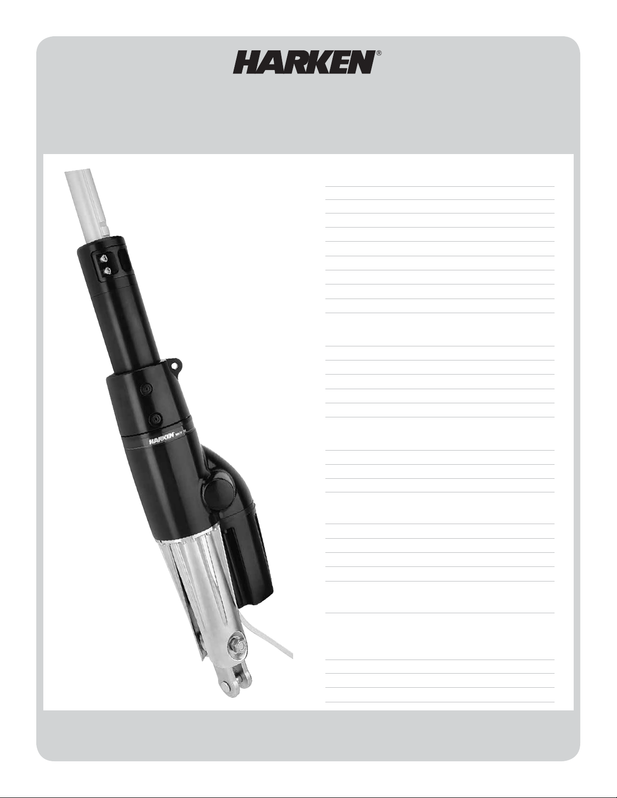
MKIV JIB REEFING & FURLING
Unit 2E, Unit 3E
Installation Manual – Intended for specialized personnel or expert users
Preassembly
Safety Precautions 2
Parts Descriptions 2 - 3
Size Check 3
Parts 4 - 5
Rigging Parts Check/Tools 6
Dimensions/Sailmaker's Instructions 7
Toggle Deductions/Stay Into Foil Options 8
Top Foil Length/Short Top Foil – 2E 9 - 10
Top Foil Length/Short Top Foil – 3E 11 - 12
Confirm Foil Length 13
Assembly
Foils/Connectors 14 - 19
Bottom Foil/Connectors/Halyard Swivel 20
Lower Unit to Foil 21
Rod Rigging 22
Attach Toggle/Short Link Plate 23 - 25
Feeder/Final 26
4676 04/14
Commissioning
Turnbuckle on Boat 27
Electrical System 28 - 29
Halyard Wrap/Prevent Halyard Wrap 30
Pendant/Halyard Restrainer/Halyard Tension 31
Operation
Spinnaker Halyards/Headstay Tension 32
Raise Sails/Storm Sails/ Furling and Reefing 33
Reefing/Secure Sail 33
Race Conversion 34
Manual Operation 35
Maintenance
Clean/Inspect/Storage/Remove Furler 36
Troubleshooting/Warranty 37
Appendix
Component Part Number List 38 - 42
Toggle Dimensions 43
Performance Charts 44
Power Cable Through-Deck Template 45
Please read these instructions carefully before installing, servicing, or operating the equipment.
This manual may be modified without notice. See: www.harken.com/manuals for updated versions.
PLEASE SAVE THESE INSTRUCTIONS
Page 2

Safety Precautions/Parts Descriptions
Introduction
This manual gives technical information on installation and service. This information is destined exclusively for
specialized personnel or expert users. Installation, disassembling, and reassembling by personnel who are not
experts may cause serious damage to property or injury to users and those in the vicinity of the product. If you
do not understand an instruction contact Harken.
The user must have appropriate training in order to use this product.
Harken accepts no responsibility for damage or harm caused by not observing the safety requirements and
instructions in this manual. See limited warranty, general warnings, and instructions in www.harken.com/manuals.
Purpose
®
Harken
Jib Reefing and Furling is designed for rolling sails on sailboats to reduce sail size or to completely roll
so wind has little effect on the sail. Use of this product for other than normal sailboat applications is not covered
by the limited warranty.
Safety Precautions
WARNING! This symbol alerts you to potential hazards that may kill or hurt you and others
if you don't follow instructions. The message will tell you how to reduce the
chance of injury.
CAUTION! This symbol alerts you to potential hazards that may hurt you and others if
you do not follow instructions. The message will tell you how to reduce the
chance of injury.
WARNING! Strictly follow all instructions to avoid potential
hazards that may kill or hurt you and others. See www.harken.com/
manuals, for general warnings and instructions.
7
6
4
3
2
1
5
8
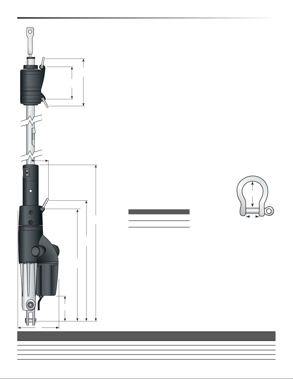
Parts Descriptions
1) Jaw/Jaw Toggle
2) Link Plates
3) Isolator
4) Lower Unit
2 MKIV Unit 2E, 3E
5) Shackles
6) Foil Clamp
7) 2' (610mm) Bottom Foil
8) Feeder
9) Connector Bushing
10) Bottom Connector
11) 7' (2.13m) Foil
12) Connector Screws
13) Connector Wedge
14) Connector
15) Halyard Swivel
16) Trim Cap
17) Trim Cap Screws
Page 3

Preassembly Sizing Check
17
16
15
13
14
12
11
9
Online Product Registration
www.harken.com/FurlingWarranty
10
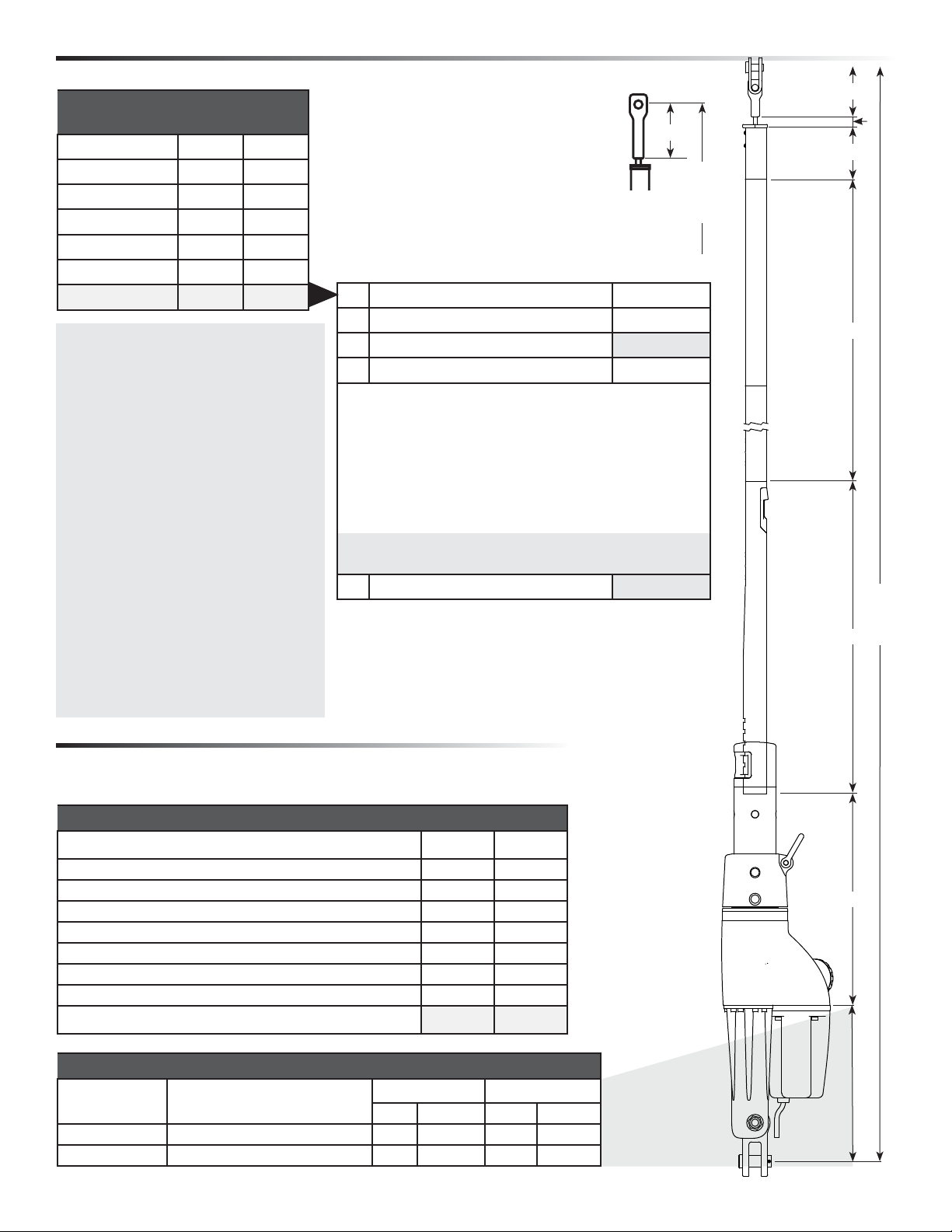
Size Check
1. Check headstay and clevis pin dimensions in chart below.
WARNING! Do not drill boat's chainplate or toggle. This may
result in rig failure. Use the correct size toggle and clevis pin.
2. Do not drill boat’s chainplate or toggle. Bushings may be required to fit boats with
smaller clevis pin sizes.
3. Will lower unit fit on bow? See page 7. If necessary, use an additional toggle to slightly
raise unit.
Unit Part No. Description Wire Ø
5
7412.13 12V
7412.13 24V
Toggle Part No. Description Chainplate Clevis Ø
UNIT 2E
MKIV Electric Unit 2E
7412.22 5/8 Jaw/jaw toggle w/short link plate
7413.22 3/4 Jaw/jaw toggle w/short link plate
/16", 3/8" 8 mm, 10 mm
Rod Ø
-12, -17, -22 7.14 mm, 8.38 mm, 9.53 mm
5
/8" 15.9 mm
3
/4" 19.1 mm
Chainplate Clevis Pin
Unit Part No. Description Wire Ø
7
7413.13 12V
7413.13 24V
MKIV Electric Unit 3E
/16", 1/2" 11 mm, 12 mm
Rod Ø
-22, -30 9.53 mm, 11.10 mm
Toggle Part No. Description Chainplate Clevis Ø
UNIT 3E
7413.22 3/4 Jaw/jaw toggle w/short link plate
7413.22 7/8 Jaw/jaw toggle w/short link plate
MKIV Unit 2E, 3E 3
3
/4" 19.1 mm
7
/8" 22.2 mm
Page 4
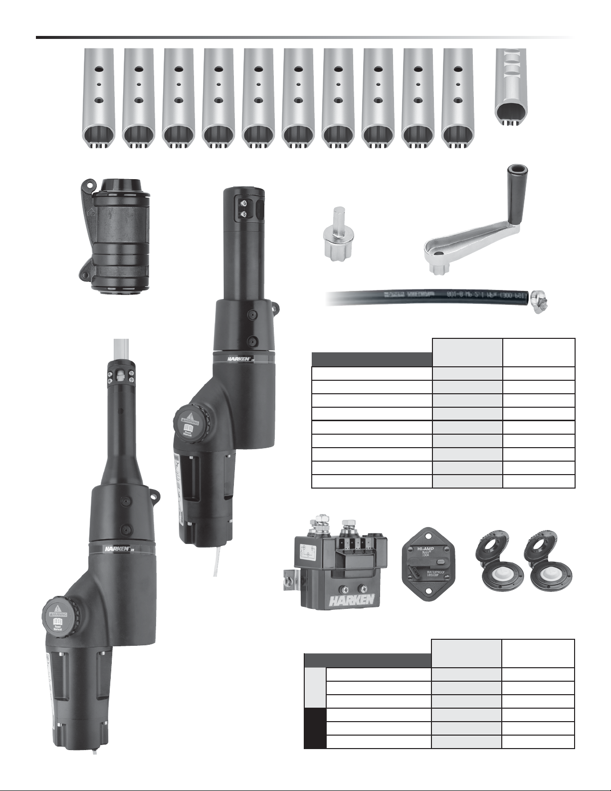
Preassembly Parts
2' (610mm)
Bottom Foil
7' (2.13m) Foils
Emergency
Crank Handle
Drill Adapter for
Manual Drive
Lower Unit
Unit 3E
Halyard Swivel
Lower Unit
Unit 2E
Parker Hose 801 and Hose Clamp
Main Components
Description
7'(2.13m) Foil
2'(610mm) Bottom foil
Halyard Swivel
12V Lower Unit with Clamp
24V Lower Unit with Clamp
Drill Adapter for Manual Drive
Emergency Crank Handle
Parker Hose 801
Hose Clamp
1
/2" ID, 2' (610 mm)
UNIT 2E UNIT 3E
Part No. Qty Part No. Qty
7412.31
7412.33
H-39794
7412.13 12V
7412.13 24V
7431
7430
—
—
8
1
1
1
1
1
1
1
1
7413.31
7413.33
H-39392
7413.13 12V
7413.13 24V
7431
7430
—
—
10
1
1
1
1
1
1
1
1
Electric Components
4 MKIV Unit 2E, 3E
Electric
Control Box
Description
Electric Control Box
40 AMP Circuit Breaker
12-VOLT
Remote Switch w/Guard
Electric Control Box
30 AMP Circuit Breaker
24-VOLT
Switch
Circuit Breaker
Part No. Qty Part No. Qty
BEB500.12.1
HCP 1918
BRS104/P
BEB500.24.1
HCP 1917
BRS104/P
Remote Switch
w/Guard
UNIT 2E UNIT 3E
BEB500.12.1
1
HCP 1918
1
BRS104/P
2
BEB500.24.1
1
HCP 1917
1
BRS104/P
2
1
1
2
1
1
2
Page 5
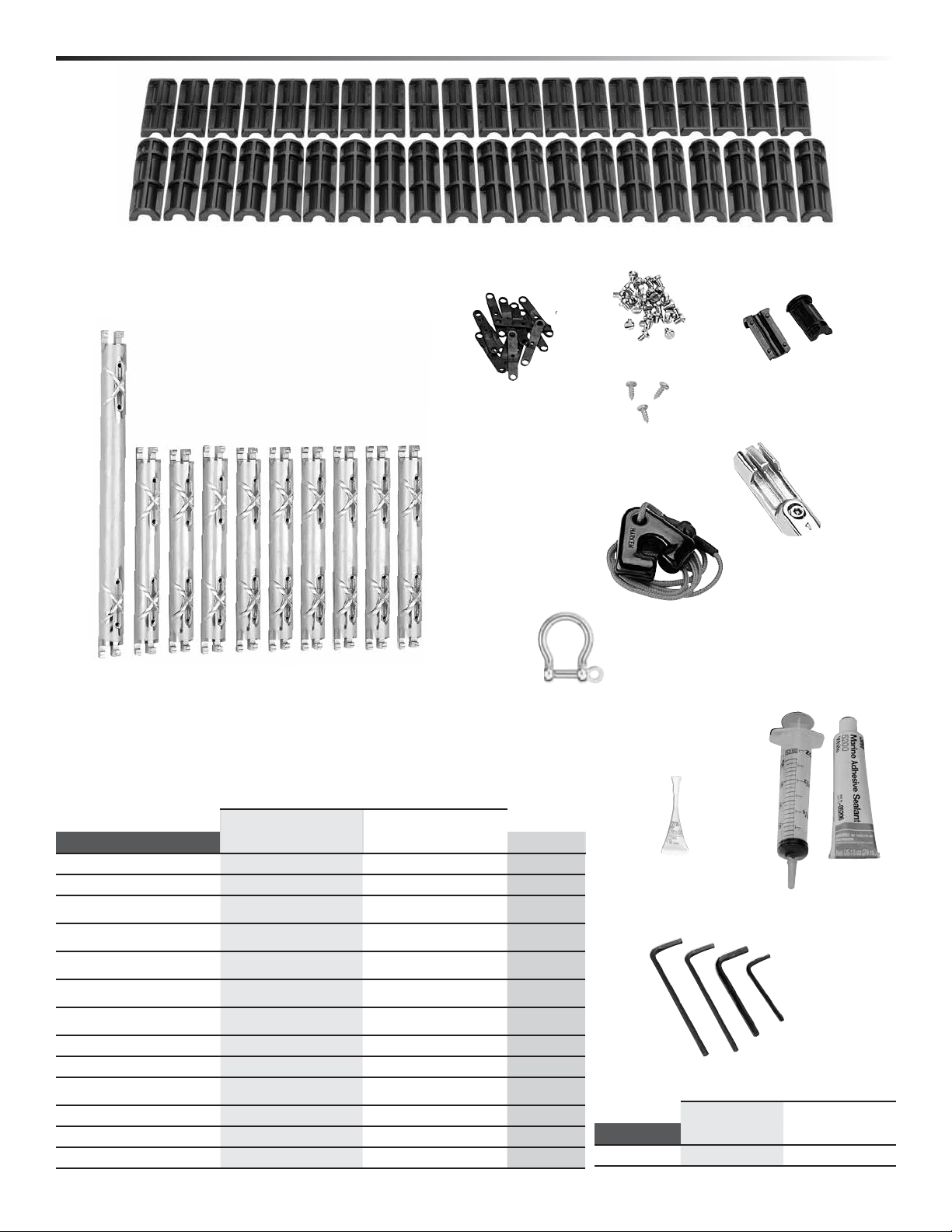
Preassembly Parts
Connector Bushings
Foil Screws
Plastic
Connector
Wedges
Trim Cap Screws
Trim Cap
Feeder
Prefeeder
Bottom
Connectors
Connector
Bow Shackles
Other Components UNIT 2E UNIT 3E
Description
Connectors
Bottom Connector
Connector bushing set
Plastic connector wedge set
Foil screw set
Trim cap set
Trim cap screw set
Prefeeder
Feeder with screw and tab
Bow shackle
Blue Loctite
Red Loctite
®
®
Injector, 1 oz. 5200 Adhesive
MKIV Unit 2E, 3E 5
Part No. Qty Part No. Qty Size
7412.31F
7412.32F
HFG296
(16 EA H-42032/H-42033)
HFG300
(18 EA H-39487)
HFG348
( 38 EA HFS1106)
HFG681
( H-37403/H-37404)
HFG672
( 3 EA HFS1127)
947
H-39559
2117
(8 mm)
833
HFG739
HFG725
7
1
1
1
1
1
1
1
1
1
1
2
1
7413.31F
7413.32F
HFG297
(20 EA H-42073/H-42074)
HFG324
(22 EA H-39487)
HFG349
( 46 EA HFS1106)
HFG682
(Missing)
HFG672
( 3 EA HFS1127)
947
H-39756
2124
(10 mm)
833
HFG739
HFG725
9 9.75" (248mm)
1 14" (356mm)
1 —
1 —
1 —
1 —
1 —
1 —
1 —
1 —
1 .017 oz.
2 .017 oz.
1
1 oz.
Blue Loctite
Red Loctite
®
®
5200
Adhesive
Injector
3, 4, 5, 6, 10 mm
Tools UNIT 2E UNIT 3E
Description
Qty Size Qty Size
Hex keys 1 Ea 3, 4, 5, 6 mm 1Ea 3, 4, 6, 10 mm
Page 6
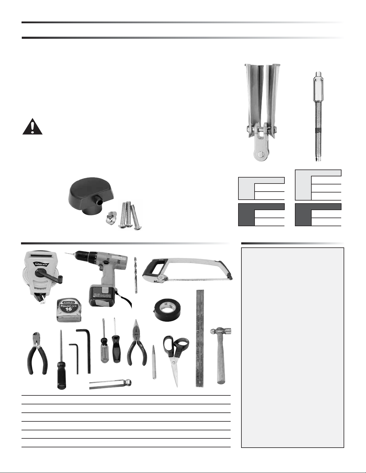
Preassembly Rigging Parts Check/Tools/Adhesive
Toggles
1. Harken jaw/jaw toggle and link plate assembly required. Sold separately.
2. Mating turnbuckle components, with eye at lower end, must be purchased
separately. See page 8.
Harken Toggle/
Link Plate Assembly
(Sold Separately)
ROD RIGGING
Harken Rod Adapter
Stud Required
(Sold Separately)
3. Headstay may require cutting and shortening to fit Harken toggle. Some
headstays may remain uncut by replacing lower stud of turnbuckle with
stud/eye thus eliminating extra toggle.
4. Rod rigging requires Harken rod adapter stud.
WARNING! Wire that is old or damaged may break suddenly,
causing an accident. Headstay condition should be checked
by a professional rigger before reusing.
5. Harken 7406 through-deck fitting for routing power wires through the
1
deck. Fits
35 mm fasteners and hose clamp. See page for template.
7406 Aluminum
through-deck fitting
for routing wires
belowdecks
/2" ID parker hose supplied with unit. Includes three (3) 6 mm x
Jaw/Jaw Toggle
w/ Link Plate
Unit Part No.
7312.22 5/8
2E
7413.22 3/4
Unit Part No.
7413.22 3/4
3E
7413.22 7/8
Rod Adapter Stud
Unit Part No.
7424 -12
2E
7425 -17
7426 -22
Unit Part No.
7426 -22
3E
7427 -30
Tools You Will Need
3
10
16
4
12
13
11
1
2
8
6
7
1. Long tape measure 6. Side cutters 11. Center punch
2. Short tape measure 7. Rat-tail file 12. Rigging or black tape
3. Power drill 8. Hex keys (provided) 13. Scissors
4. Drill bit – 5/32" (4mm) 9. Slotted/phillips screwdrivers 14. Metal straight edge
5. Hacksaw 10. Needle-nose pliers 15. Hammer
16. 5 mm Ball-end hex key wrench (recommended but not required)
6 MKIV Unit 2E, 3E
9
5
14
15
Adhesive Alert
MKIV Furlers are shipped with 3M® 5200
adhesive. Use adhesives on dry connectors
and foils using the special injection system
described in the assembly section. Parts
may immediately be exposed to rain. Cure
is best at 70 F (22C) with 50% humidity.
Do not apply at temperatures below 40 F
(5C) and above 100F (38C).
Although adhesive has not cured it will
remain in place on foil joints whether
they are left on the ground or raised up
on boat. Foils can be raised immediately
after assembly and sails fitted.
Note: A small amount of adhesive may
bulge out of injection ports. If possible
let system sit for a couple days before
sailing. If adhesive gets on sails remove
using acetone. For faster-curing adhesive,
purchase 4200 Fast Cure.
Note: Damaged foils can be repaired.
Use a hand-held propane torch to heat
joints until foils can be pulled apart.
Page 7
Preassembly Dimensions/Sailmaker's Instructions
Luff Length
Note offsets above and below sail.
A shorter luff may be required if a halyard restrainer is used or an
additional toggle assembly is used to raise unit.
If luff of sail is not long enough to put halyard swivel near top of
headstay foil, a pendant must be added. See page 29.
B
Tack Setback
A
Note setback for tack shackle and cut sail accordingly.
Luff Tape Size
6
Unit 2E and 3E require #6 (
/32" or 5mm) luff tape.
Luff Tape Length
Cut off top of luff tape so it is 18 to 24" (450 to 600 mm) below head
of sail. This allows head to lag behind rest of sail to help flatten sail.
It will also help head to roll more smoothly.
Note feeder height and extend bottom of luff tape downward so it is
C
below feeder. This will prevent luff tape from catching in feeder as
sail is lowered.
Tack and Head Shackles
Make sure tack and head shackles fit sail
rings. Minimum inside dimensions of
A
standard head and tack shackles are:
Unit A B
3
2E
1
D
/4" (44 mm)11/16" (17 mm)
7
3E
/8" (48 mm)13/16" (21 mm)
1
B
Sun cover
E
Sun covers may be installed on either side of sail. Be
sure to match other sails in the customer's inventory.
F
G
H
Part
No.
7412.13 with 7312.22 5/8 toggle 5
7412.13 with 7413.22 3/4 toggle 5
7413.13 with 7413.22 3/4 toggle 7
7413.13 with 7413.22 7/8 toggle 7
MKIV Unit 2E, 3E 7
A B C D E F G H
in mm in mm in mm in mm in mm in mm in mm in mm
3
/8143 91/8231 31/482 331/16841 241/2622 225/8574 41/2116 811/32212
3
/8143 91/8231 31/482 3311/19856 253/32637 231/4590 53/16132 811/32212
5
/16186 115/8296 31/482 321/2826 253/32637 231/4590 53/16132 811/32212
5
/16186 115/8296 31/482 333/16840 2511/16652 2313/16605 53/4146 811/32212
See toggle dimensions in appendix
Page 8

Preassembly Toggle Deductions/Stay Into Foil Options
Use dimensions of Harken toggle below to build stay to correct length.
Tip: Turnbuckles should be 1/2 to 2/3 open to allow shortening for new wire stretch and for fine-tuning mast rake.
Note: Turnbucke assembly with eye
at lower end not supplied by Harken
Unit Clevis Pin Ø Pin-to-Pin Length
5
/8" (15.9mm) 25/8" (67mm)
2E
3
/4" (19.1mm) 39/32" (83mm)
Unit Clevis Pin Ø Pin-to-Pin Length
3
/4" (19.1mm) 39/32" (83mm)
3E
7
/8" (22.2mm) 37/8" (98mm)
Options for Snaking Stay into Foils
1. Swage stud at end of wire.
2. Open end of wire and install Norseman or Sta-Lok
®
stud after foil is assembled.
3. Rod adapter nosepiece for Harken rod adapter stud: Threaded nosepiece must
have a positive lock of as well as adhesive. Use Harken stud with cotter pins.
See page 22.
WARNING! Using a threaded nosepiece with only adhesive at the
upper rod eye terminal may result in headstay system failure.
Make sure there is a mechanical lock.
8 MKIV Unit 2E, 3E
Page 9

Preassembly Top Foil Length
Measure A and add to this chart
and length chart below
Inches mm
A
B 63 16
E 24 610
F 17.5 445
G
Total A+B+E+F+G
UNIT 2E
Make sure upper
measurement points
of A and Pin-to-Pin
Alternate
Measurement
Point
A
are the same.
TOP FOIL LENGTH WORKSHEET
1
2
3
4
To find “D” pick number from chart below that is closest to,
but not greater than total from step 3.
500 inches “D” = 420 12,000 mm “D” = 10,668 mm
5
Result (Pin-to-Pin – ABEFG)
Inches mm
5 x 84 = 420
6 x 84 = 504
7 x 84 = 588
8 x 84 = 672
9 x 84 = 756
Example–If result from Step 3 is:
Result (C) Top Foil Length
Pin-to-Pin Length
Subtract ABEFG
Subtract D
5 x 2133.6 = 10668.0
6 x 2133.6 = 12801.6
7 x 2133.6 = 14935.2
8 x 2133.6 = 17068.8
9 x 2133.6 = 19202.4
–
–
Pin
to
Pin
A
B
C
D
Pin
to
Pin
E
Length Check
After completing worksheet above fill in A, C, D and G below. Add
“A” through “G” to confirm total equals your pin-to-pin measurement.
Length Chart
Dimensions Inches mm
A Center of Pin to Bottom of Terminal
B Bottom of Terminal to Top of Foil
C Top Foil Length
D Number of Foils ________ x 84" (2133.6mm)
E Bottom Foil 24.0 610
F Bottom of Foil to Top of Link Plates 17.5 445
G Top of Link Plate to Clevis Pin
63
Pin-to-Pin Length
G Toggle Distance from Lower Clevis Pin to Top of Link Plates
Toggle
Part No.
7312.22 5/8 Jaw/Jaw with Link Plate
7413.22 3/4 Jaw/Jaw with Link Plate
MKIV Unit 2E 9
Type
Clevis Pin G Distance
in mm in mm
5
/8 15.9 11.67 296
3
/4 19.1 12.27 312
16
F
G
Page 10

Preassembly Unit 2—Short Top Foil
UNIT 2E
UNIT 2E
If top foil is shorter than 8
11
/16" (221 mm), use one of the following special techniques to ensure sufficient
bearing surface for the foil in the area of the halyard swivel.
/16" (221 mm)
11
8
811/16" (221 mm) No special treatment required.
/8" (219–162 mm)
3
/8"–6
5
8
Cut-Offs
Do Not Use
85/8" – 63/8" (219–162 mm) Do not use plastic bushing
above top connector.
/2" (64 mm)
1
3" (76 mm)
/2" (38 mm)
1
2" (51 mm)
2
1" (25 mm)
1
Cut-Offs
Do Not Use
3"–1" (76–25 mm) Shorten top foil and adjoining full
length foil so two screws are used to assemble joint
instead of four. Do not use plastic bushings above top
connector.
Top Foil
Length from
Worksheet
3"
(76 mm)
1
/2"
2
(64 mm)
2"
(51 mm)
1
/2"
1
(38 mm)
1"
(25 mm)
1. Initial
top foil
cut length
7
(184 mm)
63/4"
(172 mm)
6
(159 mm)
53/4"
(146 mm)
5
(133 mm)
1
/4"
1
/4"
1
/4"
2. Cut through
middle hole in
top foil.*
Resulting Top
Foil Length Length
51/8"
(130 mm)
45/8"
(117 mm)
41/8"
(105 mm)
35/8"
(92 mm)
31/8"
(79 mm)
3. Shorten
full length
adjoining
foil by
cutting
through
middle
hole.*
4. Shorten
connector
(114 mm)
(114 mm)
(114 mm)
(95 mm)
(95 mm)
41/2"
41/2"
41/2"
33/4"
33/4"
5. Shorten
trim cap
No
No
No
Yes
Yes
/2" (152–140 mm)
1
6"–5
Cut-Offs
Do Not Use
6"–51/2" (152–140 mm) Do not use plastic bushing
above top connector. Shorten top of connector and if
necessary shorten trim cap.
/8" (133–92 mm)
5
/4"–3
1
5
Cut-Offs – Do Not Use
51/4"–35/8" (133–92 mm) Do not use plastic bushing
above top connector. Cut connector right at cross formed
by glue dispersion channels. Use single foil screw in top
foil only.
10 MKIV Unit 2E
Cut-Off
Do Not Use
*To allow for saw cut, position blade so upper half of
middle hole is preserved.
Under 1" (25 mm)
Under 1" (25 mm) Eliminate top foil and run foil higher
in torque tube.
Page 11
Measure A and add to this chart
and length chart below
Inches mm
A
B 1 25
E 24 610
F 15.41 391
G
Total A+B+E+F+G
UNIT 3E
Make sure upper
measurement points
of A and Pin-to-Pin
Alternate
Measurement
Point
A
are the same.
TOP FOIL LENGTH WORKSHEET
1
2
3
4
To find “D” pick number from chart below that is closest to,
but not greater than total from step 3.
800 inches “D” = 756 inches 20,000mm “D” = 19,202mm
5
Result (Pin-to-Pin – ABEFG)
Inches mm
7 x 84 = 588
8 x 84 = 672
9 x 84 = 756
10 x 84 = 840
11 x 84 = 924
Example–If result from Step 3 is:
Result (C) Top Foil Length
Pin-to-Pin Length
Subtract ABEFG
Subtract D
7 x 2133.6 = 14935.2
8 x 2133.6 = 17068.8
9 x 2133.6 = 19202.4
10 x 2133.6 = 21336
11 x 2133.6 = 23470
–
–
Pin
to
Pin
A
B
C
D
Pin
to
Pin
E
Length Check
After completing worksheet above fill in A, C, D and G below. Add
“A” through “G” to confirm total equals your pin-to-pin measurement.
Length Chart
Dimensions Inches mm
A Center of Pin to Bottom of Terminal
B Bottom of Terminal to Top of Foil
C Top Foil Length
D Number of Foils ________ x 84" (2133.6mm)
E Bottom Foil 24.00 610
F Bottom of Foil to Top of Link Plates 15.41 391
G Top of Link Plate to Clevis Pin
1.00
Pin-to-Pin Length
G Toggle Distance from Lower Clevis Pin to Top of Link Plates
Toggle
Part No.
7413.22 3/4 Jaw/Jaw with Link Plate
7313.22 7/8 Jaw/Jaw with Link Plate
MKIV Unit 3E 11
Type
Clevis Pin G Distance
in mm in mm
3
/4 19.1 12.27 312
7
/8 22.2 12.85 327
25
F
G
Page 12

Preassembly Short Top Foil
UNIT 3E
UNIT 3E
If top foil is shorter than 9
3
/4" (248mm), use one of the following special techniques to ensure sufficient bearing
surface for the foil in the area of the halyard swivel.
/4" (248mm)
3
9
93/4" (248mm) No special treatment required.
/8" (244 - 181mm)
1
Cut-Offs
/8" - 7
5
9
Do Not Use
95/8" – 71/8" (244 – 181mm) Do not use plastic
bushing above top connector.
/2" (89mm)
/2" (64mm)
1
2
/2" (38mm)
1
2" (51mm)
1
1
3" (76mm)
3
Cut-Offs
Do Not Use
31/2" - 11/2" (89 – 38mm) Shorten top foil and adjoin-
ing full length foil so two screws are used to assemble
joint instead of four. Do not use plastic bushings above
top connector.
Top Foil
Length from
Worksheet
1
3
/2"
(89mm)
3"
(76mm)
1
/2"
2
(64mm)
2"
(51mm)
1
/2"
1
(38mm)
1. Initial
top foil
cut length
69/16"
(167mm)
6
(154mm)
69/16"
(167mm)
5
(129mm)
49/16"
(116mm)
1
1
/16"
/16"
2. Cut through
middle hole in
top foil.*
Resulting Top
Foil Length Length
5"
(127mm)
41/2"
(114mm)
4"
(102mm)
31/2"
(89mm)
3"
(76mm)
3. Shorten
full length
adjoining
foil by
cutting
through
middle
hole.*
4. Shorten
connector
(124mm)
(124mm)
(124mm)
(111mm)
(95mm)
47/8"
47/8"
47/8"
43/8"
33/4"
5. Shorten
trim cap
No
No
No
Yes
Yes
/2" (178 - 140mm)
1
7" - 5
Cut-Offs
Do Not Use
7" - 51/2" (178 – 140mm) Do not use plastic bushing
above top connector. Shorten top of connector and if
necessary shorten trim cap.
Cut-Offs – Do Not Use
/8" - 4" (137 - 102mm)
3
5
53/8" - 4" (137 – 102mm) Do not use plastic bushing
above top connector. Cut connector right at cross formed
by glue dispersion channels. Use single foil screw in top
foil only.
12 MKIV Unit 3E
Cut-Off
Do Not Use
*To allow for saw cut, position blade so upper half of
middle hole is preserved.
/2" (38mm)
1
Under 1
Under 11/2" (38mm) Eliminate top foil and run foil
higher in foil clamp.
Page 13
Preassembly Confirm Foil Length
Confirm foil length by laying foils alongside
stay with turnbuckle components.
Pull stay out so it is straight. Attach Harken
toggle to bottom of stay using crosspin.
Make sure toggle straps are straight.
Adjust turnbuckle so that length of stay
with Harken toggle will fit boat. Ideally,
turnbuckle will be half to two-thirds open
to allow for rig adjustment.
Attach one link plate to lower unit. Line up
lower unit so link plate hole lines up with
rcrosspin in Harken toggle. Make sure
toggle is tensioned when measuring.
Line up bottom foil so foil clamp is
centered or just below center of
notches in bottom foil.
Note: Position top foil so that with top
cap the foil will ride below terminal (see
chart below). If wire fitting at top of stay is
swage, foil must ride just below shoulder
of swage. Mark cut line on foil. Wrap tape
around foil as a guide so cut is straight.
Unit
5
2E
/8" (16 mm)
3E
1" (25 mm)
MKIV Unit 2E, 3E 13
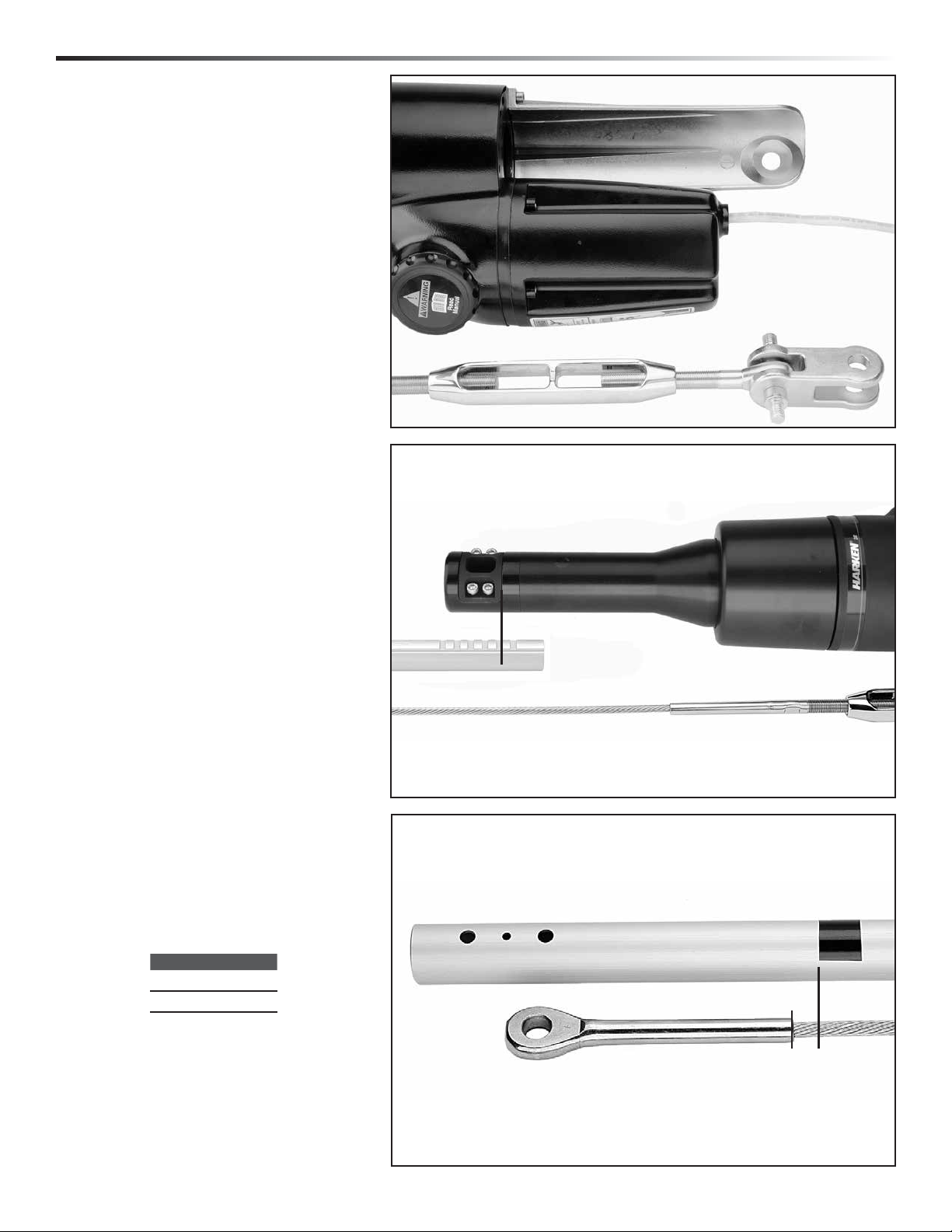
Page 14
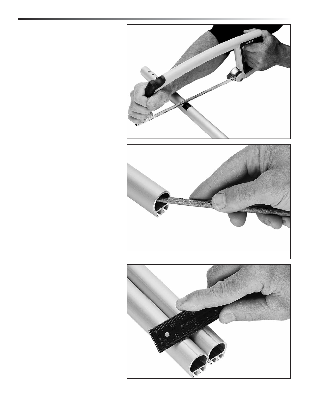
Assembly Top Foil
Cut foil to length using hacksaw.
Deburr inside edge using rat-tail file.
Prepare top foil for drilling.
Tip: Mark top foil to distinguish
from cutoff piece.
Scribe line on top of foil to mark drill
holes. Lay top foil alongside cutoff
piece and use a flat metal object
(i.e. metal ruler) to scribe top
line of foil.
14 MKIV Unit 2E, 3E
Page 15
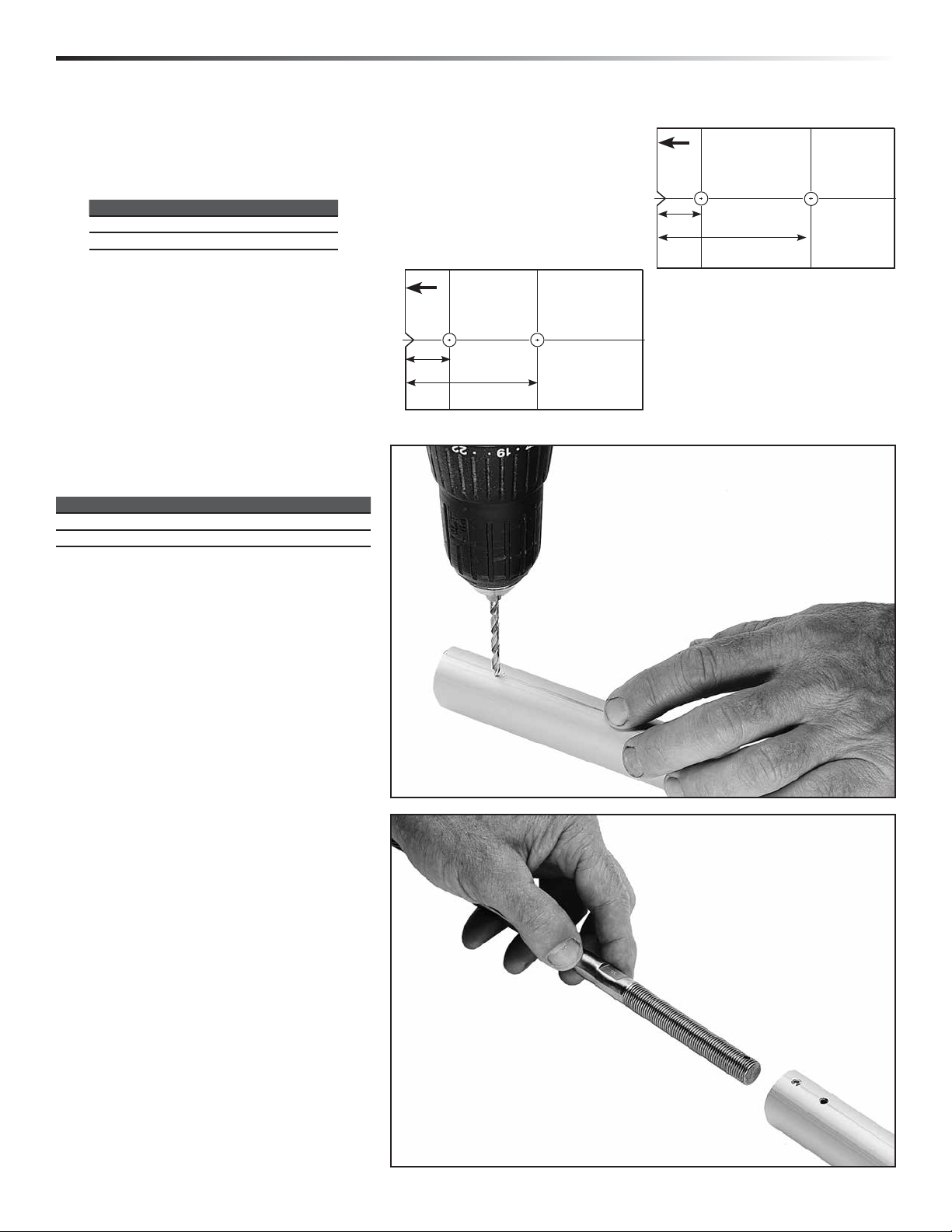
Assembly Top Foil
Cut out template at right. Line up template
with top of foil and scribed line. Tape in
place. Use center punch to mark holes.
Check center punch marks to confirm
(see chart below).
!
Foil
Top
Unit 3
Unit Center Punch Marks
2E
3E
Drill two (2) holes for trim cap. See chart
below for correct drill size
Unit Drill Ø
3 (3/4, 7/8) 5/32" (4 mm)
3
/8" (10 mm) 13/16" (30 mm)
3
/8" (10 mm) 13/8" (35 mm)
2 5/32" (4 mm)
!
Foil
3
Top
/8" (10 mm)
Unit 2
13/16" (30 mm)
3
/8" (10mm)
13/8" (35mm)
Lay top foil in line with others. Slide stay
into top foil and down line of foils or slide
each foil up stay.
MKIV Unit 2E, 3E 15
Page 16

Assembly Top Foil
Install trim cap. Place each side over wire.
Push trim cap into foil to start, then tap
in using hammer.
Install trim cap screws.
Place halves of plastic bushings on stay so
hooked part of longer section faces out.
Tip: With foil screw holes up as shown
below, place longer half of bushing
with hook on upper half.
16 MKIV Unit 2E, 3E
Page 17

Assembly Top Foil/Connectors
Slip connector on wire, mating hook
of plastic bushing with connector.
Put a drop of red Loctite® into screw holes.
MKIV Unit 2E, 3E 17
Page 18

Assembly Foils/Connectors
Hold plastic wedge in place with thumb
as you insert into foil. Line foil holes
with connector screw holes.
Loading Injector with Adhesive
Tip: In cooler weather, keep sealed
adhesive in pocket to keep warm. Use
instructions below to fill injector less
than half way; you will only use a small
amount of adhesive. Refill if needed
but do not keep open sealant for long
periods. Use adhesive within 3 hours.
Use cap of adhesive to break seal. Remove
injector tip cap and plunger. Hold injector
at an angle with applicator tip facing down.
Squeeze adhesive into tube so lower half
of injector is full as shown. Keep tip free
of sealant to let air inside.
Adhesive in
lower half
Start plunger into injector and immediately
hold upright so plunger is down and
applicator tip is up.
As sealant runs down towards plunger an
air pocket will form near tip. Push plunger
to evacuate air. You are now ready to begin
injecting adhesive.
18 MKIV Unit 2E, 3E
Page 19

Assembly Foils/Connectors
Inject only a small amount of adhesive
into middle hole.
Unit Adhesive (ml)
2
3 (3/4, 7/8) 1 – 1
3
/4 – 1
1
/
4
Tip: When you see a small amount
of adhesive enter one screw
hole, stop. You have applied
enough adhesive.
Stop when you see a small
amount of adhesive enter
one screw hole.
Use “ml”
marks to
estimate 1
1
/4ml of
to 1
adhesive
Tighten screws into connector holes. Make
sure a drop of adhesive entered each screw
hole. If not, apply to screw.
Use bushings, connector, wedge and
adhesive in other screw hole and insert
into other foil. Use adhesive (see chart
below for amount).
Unit Adhesive (ml)
2
3 (3/4, 7/8) 1 – 1
3
/4 – 1
1
/
4
Red Loctite
®
MKIV Unit 2E, 3E 19
Page 20

Assembly Bottom Foil/Connectors/Halyard Swivel
Continue installing connectors and wedges.
Make sure to use adhesive in screw holes.
Continue assembly. Use bottom connector
to assemble bottom foil.
Slide halyard swivel onto foil above feeder
window. Make sure taller “half” is up as
shown.
20 MKIV Unit 2E, 3E
Page 21

Assembly Lower Unit to Foil
Loosen foil clamp screws at top of
lower unit assembly.
Slide assembly onto foils.
Tip: Face clamp downward so it
clears foil notches during installation.
MKIV Unit 2E, 3E 21
Page 22

Assembly Rod Rigging: Rod Adapter Stud
Apply a few drops of red
®
Loctite
Screw main threaded stud
portion onto bronze nosepiece
until flats align with two cotter
pin holes in terminal body.
Tip: Turn nosepiece completely
into threaded stud portion.
Flats will be close and may
only require a small half turn
to align with cotter pin holes.
to threads of nosepiece.
Insert two cotter pins and
®
spread. Clean excess Loctite
from terminal body using
special care to ensure that
there is no red Loctite
threaded stud.
®
on
ROD RIGGING
22 MKIV Unit 2E, 3E
Page 23

Assembly Attach Turnbuckle/Toggle
Assemble turnbuckle.
®
Note: If using Sta-Lok
or Norseman®
stud, you must use a washer above
stud as shown below.
Connect eye to toggle jaw using special
clevis pin. Secure using cotter pin.
Make sure shallow jaw is up.
Up
Down
If stay length is set use side cutters or
needle-nose pliers to bend cotter pin
to secure turnbuckle.
MKIV Unit 2E, 3E 23
Page 24

Assembly Attach Toggle/Short Link Plate
Determine correct position for isolator.
Capture isolator on screws and screw
one link plate to lower unit. Use
®
blue Loctite
on screws.
Capture special crosspin between link
plates as you secure second plate to
®
lower unit. Use Blue Loctite
24 MKIV Unit 2E, 3E
on screws.
Page 25

Assembly Attach Toggle/Short Link Plate
Tip: Use a ball-end hexkey to install
screws so wrench can articulate.
Recess turnbuckle into lower unit
assembly, slip link plates over special
crosspin and secure using fasteners.
®
Use blue Loctite
on screws.
Secure to toggle using locknuts.
MKIV Unit 2E, 3E 25
Page 26

Assembly Feeder/Final
Check foil height at top, set and secure
using hex key.
Slide halyard swivel above feeder. Place
feeder in foil recess. Push screw down
so tab catches under foil. Tighten screw.
Note: Screw will turn with some difficulty.
It is plastic coated to prevent loosening
due to vibration.
IMPORTANT! When removing screw,
loosen no more than one full turn.
Slide screw up and remove feeder.
26 MKIV Unit 2E, 3E
Page 27

Commissioning Turnbuckle on Boat
Have extra cotter pins and locknuts on hand to replace used
ones at base of unit and for turnbuckle.
Hold foils and loosen foil clamp screws until you can pull clamp
out to lower foils.
Lower foils.
Remove link plates.
CAUTION! Make sure drum assembly and foils are
securely lifted using a halyard before adjusting
turnbuckle. Foils can drop suddenly causing
injury to hands.
Adjust turnbuckle.
Replace used cotter pins and locknuts. Lower unit and install
clevis pin and new cotter pin.
Lift foils so top is below upper terminal.
Unit
2E
3E
5
/8" (16 mm)
1" (25 mm)
Raise lower unit and use
halyard to lift and hold it
about 5' (1.5m). Raise foils
using second halyard and
secure. Allow room above
for turnbuckle take up.
MKIV Unit 2E, 3E 27
Page 28

Commissioning Electrical System
You must use supplied
1
/2" ID Parker
Hydraulic Hose to keep electric motor
compartment water tight.
Slip hose over the wire. Use stainless steel
hose clamp to securely tighten the hose to
the coupling extension tube. If supplied
1
hose is too short, use a similar
/2" ID
hydraulic hose.
Secure other end of hose to watertight
through deck fitting so that wires enter
a dry area of the boat.
Use optional 7406 Power Cable ThroughDeck Fitting for a watertight routing of the
power cable through the deck.
See drilling template on page 45.
3
Hole saw Ø 1
Drill size
/8" (35 mm)
1
/4" (6.25 mm)
Fasteners (Provided) 6 mm x 35 mm
If required, shorten fasteners or purchase
longer 6 mm stainless steel screws. Use
washers, not provided.
Drill large hole and fastener holes.
Make a slight bevel at the top of the screw
holes to allow sealant to form a small ring.
Use sealant around large deck hole and in
deck screw holes.
Clamp host to outside
of motor housing.
Deck
Deck
Bevel
28 MKIV Electric Unit 2E, 3E
Use 833 blue Loctite® in
screw holes in Harken
7406 through-deck fitting.
Page 29

Commissioning 12-/24-Volt System
Circuit
Breaker
Switches
M1
5 amp
Fuse
Wire 12- or 24-Volt System Wire Size/Run Chart
Run
Size
Remote Switch wire size— 14 AWG (2mm
0-5 m 0 - 16.4 ft 5 - 10 m 32.8 ft 10 - 15 m 49.2 ft 15 - 20 m 65.6 ft
2
10 mm
6 AWG 16 mm
–
–
2
).
M2
+
2
4 AWG 25 mm
Electrical System (see performance charts in appendix)
Fasten electric control box containing solenoids to bulkhead
or wall. Electrical terminals may face up or sideways. Do not
install box up-side-down. The control box will not work.
2
2 AWG 35 mm
2
1 AWG
WARNING! Mounting control box upside down
will cause the system to not operate which may
lead to an accident, resulting in damage to your
vessel, personal injury or death. See www.
harken.com for additional safety information.
Install remote circuit breaker between power supply and
electric control box.
Locate pushbuttons in a convenient spot for easy furler
2
operation. Use 14 AWG (2 mm
) for Remote Switches.
Refer to wiring diagram for Wire Size/Run Chart above
for connection information. Use ring terminals
at end of connection.
MKIV Unit 2E, 3E 29
Page 30

Commissioning Halyard Wrap/Prevent Halyard Wrap
Halyard Wraps
The most serious problem with furling systems occurs when the jib halyard
wraps around the headstay foil. Halyard wraps will keep you from furling
or unfurling and may cause serious damage to the unit and the halyard.
WARNING! In severe cases, a halyard wrap can cause loss
of control of boat and/or headstay can break suddenly.
Make sure halyard is clear of top foil before using system.
If Halyard Wraps
If halyard wraps, do not force unit to turn. Attempt to open sail by carefully
furling in and out a little at a time. If sail will unfurl, lower it by releasing jib
halyard. Severe halyard wraps can only be cleared by a professional going
aloft and freeing halyard.
If sail will not furl or unfurl, try to remove jib sheets and manually wrap
sail around headstay.
WARNING! Do not go aloft on boat’s halyards if there has been a halyard wrap. Do not use boat. Damage
to halyard, headstay, stay terminals, or connections as a result of a halyard wrap may cause these parts to
break suddenly causing mast to fall down while person is aloft. Sailing or motoring with boat after a wrap
can result in the headstay breaking and mast falling down. Before using boat, have a professional rigger
inspect and replace parts as necessary using following methods.
A professional rigger must carefully inspect the masthead area using a secure hoisting method. Inform rigger that
there has been a halyard wrap so they can avoid an accident by relying on standing rigging or halyards. Inspection
must be done while rigger is suspended from a separate crane or mast must be lowered to perform inspection. Some
professionals may rig a new line through internal masthead sheaves to serve as a temporary headstay to hold mast in
place. Wire, rod rigging, terminals, toggles, clevis pins or cotter pins must be inspected and replaced if they show any
signs of damage.
Prevent Halyard Wraps
To prevent wraps, the halyard must exert a slight pull to the rear. This allows
the foils to turn while halyard remains stationary.
WARNING! Sail must be fitted to foil length before using
to prevent halyard wraps and possible headstay loss.
1. Halyard swivel should be within top 4–6" (100–152 mm) of foil unless
8–10°
a halyard restrainer is used.
2. Halyard must pull slightly to rear (8–10°).
3. Halyard must be snug, but not too tight.
Test furler at dock, but if water is smooth an incorrect lead angle may not
be apparent. Halyard wraps usually occur in wave action when lead angle
is not correct. The 8–10° angle shown at right is critical.
30 MKIV Unit 2E, 3E
26 MKIV Unit 1
Page 31

Commissioning Pendant/Halyard Restrainer/Halyard Tension
Pendants
If the your sail luff is not long enough to position halyard swivel high
enough to create an 8–10° angle as shown, you must add a pendant.
Pendants should be made of plastic-coated wire and be permanently
attached so sail height will be correct. Adjustable- length pendants
are not acceptable, as they might not be adjusted
correctly during a sail change.
1. Raise sail, but do not attach tack shackle.
2. Position halyard swivel correctly near top of headstay.
3. Secure halyard.
4. Tie a piece of rope to sail tack.
5. Lead line through tack shackle on furling drum.
6. Tension sail.
7. Measure distance from tack shackle to sail tack and permanently
attach pendant of this length to head of sail.
8. Repeat procedure for every jib in your sail inventory.
Halyard Deflector/Halyard Restrainer
To prevent wraps, jib halyard must pull slightly to rear. On most boats,
halyard lead angle is acceptable if halyard swivel is raised to top of foil.
On some boats halyard sheaves are located too close to headstay and
a Halyard Deflector or Halyard Restrainer must be used.
Halyard restrainers should be used only when required by masthead
geometry. Restrainers tend to limit sail luff length and may cause
problems if not installed properly.
If your boat needs a Halyard Deflector, use Part No. 7303 for a Unit 2,
7304 for a Unit 3; or a Halyard Restrainer, use Part No. 945.
Restrainer should be mounted as high as possible on face of mast.
Position restrainer so that foils will not hit it when under load.
The restrainer should deflect halyard as little as possible or you may
experience difficulty in tensioning sail luff, friction when furling, and
possible damage to foils. To decrease deflection angles, shorten sail luff.
Tip: Boats used in charter service should have a halyard restrainer,
regardless of masthead geometry.
Halyard Tension
The jib halyard should be firm, but not too tight.
Tip: The luff foil system supports sail along its length so halyard
tension is used only to shape sails, not to support them. Use enough
halyard tension to remove some wrinkles along luff of sail. Do not
tension halyard enough to cause vertical wrinkles in luff of sail.
Tension to adjust position of draft in sail to suit sailing conditions.
Halyard should be firm but not tight. If in doubt, release halyard
tension. To protect sail, ease halyard when boat is not in use.
Halyard Deflector
Halyard Restrainer
MKIV Unit 2E, 3E 31
Page 32

Operation Halyards/Headstay Tension
Spinnaker Halyards
Spinnaker halyards occasionally cause problems
with furling.
WARNING! Make sure halyards are clear
of top foil before using system. In severe
cases, spinnaker halyards can jam furler
causing loss of control of boat.
On many boats it will not be possible to attach
spinnaker halyard to bow pulpit or it may be
"sucked" into jib when furling.
On some boats the spinnaker halyard lays across
headstay and will catch on halyard swivel, foils or
jib halyard. To prevent problems it may be necessary
to install a masthead bail to move spinnaker halyard
block forward and to one side.
Boats with external halyards may find it necessary to
flip both ends of spinnaker halyard behind spreaders
to prevent fouling with furling system.
Headstay Tension
A furling system will work best if headstay is tight.
A loose headstay is difficult to rotate and can cause
unusual wear on foil joints.
To adjust headstay tension, remove sail and follow
instructions on page 27.
Tip: Before adjusting headstay tension, slack
mainsheet and vang.
Backstay Adjusters
Backstay adjusters allow headstay tension to be varied to change sail shape to
match conditions. They permit a very tight headstay to be eased when boat is not
in use. For best performance, consider adding a backstay adjuster; either a block and
tackle, a mechanical adjuster like those offered by Harken, or a hydraulic adjuster.
Remember to keep headstay tight for best performance when furling or reefing.
If your boat is fitted with an adjuster be sure that it is tensioned before the halyard
is tensioned. If not, backstay adjuster may increase halyard tension and could
damage the sail or furling system.
Racing boats often slack the headstay completely when sailing downwind. Check
to be sure that foil does not jam against upper headstay terminal when backstay
is released. To prevent this, it may be necessary to shorten foil slightly.
32 MKIV Unit 2E, 3E
Page 33

Operation Raise Sail/Storm Sail/Reefing
Raise Sails
1. Install prefeeder by securely tying end of line to a deck fitting or to toggle below
furler so it is 2' (610 mm) below feeder.
2. Shackle tack of sail to lower unit. Install shackle so screw pin head is on same side
as sun cover.
3. Secure genoa sheets to clew of sail.
4. Attach genoa halyard to halyard swivel.
5. Pass luff tape through prefeeder and feeder into foil groove.
6. Attach head of sail or pendant at head of sail to halyard swivel.
7. Hoist sail.
8. Attach genoa tack to Lower Unit shackle.
8. Once sail is raised, determine the direction of furling so suncover will shield sail
from UV rays when furled.
9. Suncover on port side of sail, furl clock-wise. Suncover on starboard, furl
counter-clockwise.
Tip: Once you have determined the direction of furl to match the suncover, mark
remote furler switches, i.e. “furl/unfurl” or “in /out”.
Tip: New sails are often stiff and may hang up on prefeeder during raising. Do
not force sail when it hangs up—lower and remove twist. Sails "break in" with
use and will become easier to raise.
Storm Sails
Most people will use one multi-purpose genoa for all their sailing, but it is not good seamanship to go offshore
without storm sails.
Heavy-air working jibs and storm sails may be used with your unit. These sails need to have luff tape added to allow
them to be raised in headstay foils.
These sails will generally require pendants to ensure that halyard swivel is properly positioned at top of headstay.
See page 29.
Remember that heavy-air working jibs and storm jibs may be reefed and furled like any other sail.
Furl and Reef
To furl or reef, ease jib sheets and press correct
switch to furl sail.
In very light air, it may be necessary to place
some tension on jib sheet to insure a tight furl.
To furl in a breeze, ease sheets gradually and furl
sail in smaller increments until sail is furled or
reefed.
When furling or reefing, make sure that nothing
is jammed. Review swivel height, lead angle, halyard restrainer information. Make sure operator has a good view of sail
and stops furling when sail is rolled and sheets have a wrap or two on the furled sail. Stop immediately if sheets jam or
halyard wraps. If operator does not have a good view, station a crew member with good visibility and communicate to
operator. If motor is laboring stop and check for reason. Consult the Troubleshooting Guide on page 36.
WARNING! Failure to stop and free a wrapped halyard can result in breakage of halyard or headstay,
possibly resulting in an accident, damage to your vessel, personal injury or death.
MKIV Unit 2E, 3E 33
Page 34

Operation Reefing Tips/Secure Sail/Race Conversion
Reefing Tips
A sail may be partially furled before you resume sailing.
This is known as reefing.
Many sailors find it helpful to place marks on foot of sail
so that they can reef to a variety of predetermined jib
sizes. This allows marks to be placed on jib lead tracks
or toe rail so that lead block position can be changed
to correspond to reefed jib.
Sails are generally reefed to balance boat and to reduce
heeling moment. Sails may also be reefed to improve
visibility or to slow boat while sailing in congested
areas or entering or leaving harbors.
Secure Sail
When furling prior to leaving your boat in slip or on
mooring, be sure that you get a tight furl and continue
furling system until sheets wrap around rolled sail two
or three times. Some people secure sail with shock
cord or sail ties.
Race Conversion
Race conversion allows use of both grooves
for sail changes and tacking genoas on deck
for use of maximum luff length genoas.
Halyard Swivel Below Feeder
Use halyard to lift halyard swivel up, away
from feeder. Loosen screw one revolution
only. Slide screw up and hold. Remove
feeder carefully—bottom end first. Don’t
lose the feeder overboard! Lower swivel
onto lower unit. Replace feeder.
Remove Feeder
Loosen screw one revolution only. Slide screw up and hold.
To Remove
Feeder For
Racing
1.
2.
1. Loosen screw
one revolution only.
2. Slide screw up.
Remove feeder.
3. Lower halyard
swivel.
Carefully remove feeder–bottom end first.
Don't drop the feeder overboard!
34 MKIV Unit 2E, 3E
Page 35

Operation Manual Operation
Before using the system, make sure that the emergency
handle can rotate and not hit the bow pulpit.
Cordless drill adapters work well, but there must be a
fully-charged cordless drill on hand at all times. Because
a cordless drill may lose power, always have an
emergency handle onboard.
WARNING! You must have a reliable manual
drive procedure in place before using the
system. Failure to have a manual drive
procedure can lead to an accident. See www.
harken.com/manuals for additional safety
information.
Drill Adapter for
Manual Drive
Emergency
Handle
Furling on Reefing with Manual Power
In the event of power failure it is necessary to go
forward and lower sail or furl by hand.
WARNING! You must observe all personal
safety precautions including using a harness
and secure tether and personal flotation device
(PFD) when going forward to bow. Failure to
have a tether system and PFD can result in
falling overboard and death.
1. Disconnect power.
2. Communicate to all crewmembers that you are going
to work on the furler. Tell them to not attempt to
restore power while you are working on the furler.
3. Have an emergency handle available.
4. Using all personal safety precautions including PFD,
harness and tether, go forward.
5. Check to make sure the power is off to the furler.
6. Remove the manual drive socket by unthreading the
cap as shown above.
7. Use the emergency handle or a cordless drill to turn
the foil until the sail is reefed or furled.
8. Inform crewmembers when you are finished.
9. Attempt to restore power to the furler.
MKIV Unit 2E, 3E 35
Page 36

Maintenance Clean/Inspect/Replace Line/Remove Furler
Clean and Lubricate
Keep unit clean. When you wash boat, flush unit with soap
and fresh water. Occasionally lower sail and flush halyard
swivel with soap and fresh water.
Foils may be cleaned by washing with soap and water.
A scrap of luff tape may be run up foil to scrub inside
®
grooves. Sail luff tapes may be sprayed with McLube
to reduce friction during sail changes.
WARNING! Spray sails off boat so Mclube®
spray does not contact deck. Decks sprayed with
McLube will be very slippery which can lead to
slipping and falling overboard.
WARNING! Parts can wear, loosen, or corrode
and can break at load. Periodically inspect items
listed below and any others as necessary. See
www.harken.com/manuals for additional safety
information.
Inspect
Inspect unit for signs of chafe, wear or damage.
Inspect clevis and cotter pins below and inside lower unit for
signs of loosening. Check headstay tension for signs of loosening.
Inspect swage fitting and lower toggle for signs of stress
corrosion.
Inspect Norseman or Sta-Lok terminal or rod terminal for
signs of loosening.
Inspect all screws on unit to be sure they have not loosened.
Inspect foil to make sure that it has not dropped into lower unit.
Periodically inspect wire for signs of wear or unraveling.
Storage – Mast Down
In areas where it freezes, do not store system where water can accumulate in foils. When water freezes it will rupture
aluminum. Store foils under cover, with grooves facing down or on an angle so water will run out.
Storage/Transporting
Do not store or transport system with lower unit extending beyond mast. Remove lower unit and halyard swivel for
storage and transport.
After Storage or Transport
After storing or transporting unit, clean thoroughly including tack and halyard swivel ball bearings. See instructions
above.
Loosen Foil Clamp Before Slacking Backstay
In order to prevent foils from locking against upper stay terminal when backstay is released, loosen foil clamp screws and
lower foil before loosening backstay.
36 MKIV Unit 2E, 3E
Page 37

Troubleshoot
Problem Probable Cause Solution
Sail will not furl or
is difficult to furl.
Sail will not unfurl
or will not unfurl
completely.
Sail will not furl
completely.
Headstay rotates in
jerks or elliptically.
Sail does not stay
furled.
Sail will not go up.
Sail will not raise
completely or luff
will not tension.
Sail will not
come down.
Ultraviolet cover rolls
up inside of sail.
Loctite® is a registered trademark of Henkel AG & Company KGaA
™
is a registered trademark of McGee Industries, Inc.
McLube
®
is a registered trademark of Sta-Lok Terminals, Ltd.
Sta-Lok
™
is a registered trademark of Minnesota Mining and Manufacturing Company AkA 3M CORPORATION
3M
Jib halyard is wrapping around headstay because
angle between mast and and halyard is too shallow
Jib halyard is wrapping around the headstay
because halyard swivel is too low.
Jib halyard is too tight. Ease jib halyard.
Foils riding on turnbuckle. Raise foils. See adjusting turnbuckle on page 27.
Foils too high, binding on swage eye. Lower foils until clear. See adjusting turnbuckle on page 27.
Spare halyard is wrapping in sail as it furls. Secure spare halyards away from furling headstay by flipping them behind spreaders
Salt or dirt in bearings. Flush bearings with freshwater and lubricate with dry spray lubricant such as McLube
Sail full of wind. Luff completely before furling or reefing.
Sail flogging too much. Release a short length of sheet, furl a small amount and repeat.
Foil out of clamp. Reinstall foil in lower unit and tighten clamp screws.
Halyard swivel installed upside down. Remount swivel correctly.
Jib halyard is wrapping around headstay because
angle between mast and halyard is too shallow.
Jib halyard is wrapping around the headstay
because the halyard swivel is too low.
Foils riding on turnbuckle. Raise foils. See adjusting turnbuckle on page 27.
Foils too high, binding on swage eye. Lower foils. See adjusting turnbuckle on page 27.
Jib halyard is too tight. Ease jib halyard.
Spare halyard is wrapping in sail as it furls. Secure spare halyards away from furling headstay by flipping them behind spreaders
Salt or dirt in bearings. Flush bearings with freshwater and lubricate with dry spray lubricant such as McLube
Spare halyard catching in sail as it furls. Move halyards away from furling headsail as above.
Insufficient tension on headstay. Tighten headstay and/or backstay to eliminate sag in headstay.
Sail not furled tightly on stay. Keep some tension on sheets when furling in light air to get a tight, secure wrap.
Luff tape will not go into groove. Check luff tape for fraying.
Sail catching at prefeeder. Flake sail more loosely on deck.
Dirt in groove. Attach a halyard and downhaul to a small section of luff tape and clean groove by raising
Halyard swivel is hitting end stop. Luff of sail is too long and must be recut.
Angle between halyard and mast is too sharp
and halyard is pulling too much to the rear.
Halyard is wrapping on headstay. Angle between headstay and halyard is too shallow and must be optimized per installation
Halyard swivel off foil. Sail luff too long or foil is too short or low and must be lengthened or raised.
Wrong switch used to furl sail. Unroll sail and use other switch to furl. Alternatively, rewire switch if preferred. Once
See installation instructions regarding optimal halyard angle. It may be necessary
to mount a halyard restrainer on front of your mast to hold halyard to rear.
See installation instructions regarding optimal halyard swivel height. A wire pendant
may be needed at head of sail to raise halyard swivel to proper height.
See installation instructions regarding optimal halyard angle. It may be necessary to
mount a halyard restrainer on front of your mast to hold halyard to rear.
See installation instructions regarding optimal halyard angle.
Check luff tape size.
and lowering.
Halyard must be routed from a point higher on mast. This may require that halyard turning
block aloft be replaced or sail shortened.
instructions.
correct one is determined, label switch "furl" and the other "Unfurl."
®
®
Warranty
Online Product Registration
www.harken.com/FurlingWarranty
or call, write, email or fax Harken, Inc.,
www.harken.com/manuals
Pewaukee, WI USA
MKIV Unit 2E, 3E 37
Page 38

Unit 2E Parts List
UNIT 2E
UNIT 2E
HFS747
H-42346
1
Description Order Part No.
Torque Tube Screws 4 HFS747
1
Torque Tube Clamp 1 H-42346
Lower Unit 12V 1 7412.13BASE 12V
2
3
Manual Drive Cap 1 H-40516
Cap Safety Label 1 4665
Lower Unit 24V 1 7412.13BASE 24V
Manual Drive Cap 1 H-40516
Cap Safety Label 1 4665
Motor Housing Kit 12V 1 H-64051
Motor Housing Kit 24V 1 H-64052
7412.13BASE 12V / 7412.13BASE 24V
H-40516
4665
2
H-64051 12V
H-64052 24V
Old style used
on Unit 2E purchased before
December 2013
Replace with
H-64051 12V
H-64052 24V
3
38 MKIV Unit 2E, 3E
Page 39

Unit 2E Parts List
PLEASE SAVE THESE INSTRUCTIONS
UNIT 2E
UNIT 2E
HFG672
7412.13 FOILSET
7412.31
7412.32
H-38028A
MP-127
MP-127
MP-127
H-38028A
HFG348
HFG626
HFG681
HFS1127
H-39794
HFS1106
7412.30
7412.31
H-42032
H-42033
7412.32
H-39487
4
Description Order Part No.
Trim Cap Set w/o Screws 1 HFG681
4
Trim Cap Screw Set 1 HFG672
Trim Cap Screw 3 HFS1127
Halyard Swivel w/o Shackles 1 H-39794
®
Torlon
Ball Bearings 92 MP-127
Clip / Smalley Ring 2 H-38028A
Foil Set 1 7412.13 FOILSET
Foil (7' / 2.13 m) Luff 8 7412.30
Foil (2' / 610 mm) Bottom 1 7412.33
Foil Screw Set 1 HFG348
Foil Screw 38 HFS1106
Connector Set w/o Bushings 1 HFG626
Connector (9" / 229 mm) 7 —
Connector Bottom (13" / 330 mm) 1 —
Connector Bushing Set 1 HFG296
Connector Bushing (Curved / Longer) 16 H-42032
Connector Bushing (Flat / Shorter) 16 H-42033
Connector w/Bushings 1 7412.31
Connector (9" / 229 mm) 1 —
Connector Bushing (Curved / Longer) 2 —
Connector Bushing (Flat / Shorter) 2 —
Foil Screw 4 —
Connector Wedge 2 —
Connector w/Bushings Bottom 1 7412.32
Connector Bottom (13" / 330 mm) 1 —
Connector Bushing (Curved / Longer) 1 —
Connector Bushing (Flat / Shorter) 1 —
Connector Wedge Set 1 HFG300
Connector Wedge 18 H-39487
Feeder Set 1 H-39559
Feeder 1 H-33931B
Feeder Screw 1 HFS1129
Tab 1 H-35671A
H-39559
HFG296
7412.33
Description Order Part No.
HFG300
MKIV JIB REEFING & FURLING
Unit 2E, Unit 3E
Installation Manual – Intended for specialized personnel or expert users
4676/12-20-2012
Preassembly
Safety Precautions/Parts Descriptions 2 - 3
Parts 4 - 5
Rigging Parts Check/Tools 6
Dimensions/Sailmaker's Instructions 7
Toggle Deductions/Stay Into Foil Options 8
Top Foil Length/Short Top Foil – 2E 9 - 10
Top Foil Length/Short Top Foil – 3E 11 - 12
Confirm Foil Length 13
Assembly
Foils/Connectors 14 - 19
Bottom Foil/Connectors/Halyard Swivel 20
Lower Unit to Foil 21
Rod Rigging 22
Attach Toggle/Short Link Plate 23 - 25
Feeder/Final 26
Commissioning
Turnbuckle on Boat 27
Electrical System 28
Halyard: Swivel Height/Lead Angle 29
Halyard: Restrainer/Tension 30
Operation
Halyards/Headstay Tension 31
Raise Sails/Storm Sails/Reefing 32
Reefing Tips/Secure Sail/Race Conversion 33
Race Conversion 33
Manual Operation 34
Maintenance
Clean/Inspect/Storage/Remove Furler 35
Troubleshooting 35
Warranty
Appendix
Component Part Number List 37 - 41
Toggle Dimensions 42
Performance Charts 43
Please read these instructions carefully before installing, servicing, or operating the equipment.
This manual may be modified without notice. See: www.harken.com/manuals for updated versions.
4676
833
HFG739
HFG722
5
945
2117
HFG644
HFG643
6
HFG640
HCP1089
947
HFG200/HFG201
MKIV Unit 2E, 3E 39
Instruction Manual 1 4676
5
Loctite® Blue 1 833
Loctite® Red 2 HFG739
5200 Adhesive Set 1 HFG725
5200 Marine Adhesive Sealant 1 HFG722
Injector 1
Prefeeder 1 947
Description Order Part No.
Halyard Restrainer (Optional) 1 945
6
Sheave/SS Inner Race Only 1 945ASSY
Clevis Pin (
5
/16" x 11/4" 18-8) 1 SP-038
Bracket-Large 1 HCP394
Cotter Pin (
3
/32" x 3/4" 18-8) 1 HFS181
Bow Shackle (8 mm) 3 2117
Hex Keys
6 mm 1 HFG644
5 mm 1 HFG643
4 mm 1 HFG640
3 mm 1 HCP1089
HFG200
HFG201
Page 40

Unit 3E Parts List
UNIT 3E
UNIT 3E
HFS1107
H-42967
1
Description Order Part No.
Torque Tube Screws 4 HFS1107
1
Torque Tube Clamp 1 H-42967
Lower Unit 12V 1 7413.13BASE 12V
2
3
Manual Drive Cap 1 H-40516
Cap Safety Label 1 4665
Lower Unit 24V 1 7413.13BASE 24V
Manual Drive Cap 1 H-40516
Cap Safety Label 1 4665
Motor Housing Kit 12V 1 H-64051
Motor Housing Kit 24V 1 H-64052
7413.13BASE 12V / 7413.13BASE 24V
H-40516
4665
2
H-64051 12V
H-64052 24V
Old style used
on Unit 3E purchased before
December 2013
Replace with
H-64051 12V
H-64052 24V
3
40 MKIV Unit 3E
Page 41

Unit 3E Parts List
4676/12-20-2012
UNIT 3E
UNIT 3E
HFG672
7413.13 FOILSET
7413.31
7413.32
H-39916
MP-128
MP-128
MP-128
H-39916
HFG349
HFG627
H-39751
H-39752
HFS1127
H-39392
HFS1106
7413.30
7413.31
H-42073
H-42074
7413.32
4
Description Order Part No.
Trim Cap w/o Screws
4
Top (with Holes) 1 H-39751
Bottom (with Pegs) 1 H-39752
Trim Cap Screw Set 1 HFG672
Trim Cap Screw 3 HFS1127
Halyard Swivel 1 H-39392
®
Torlon
Ball Bearings 88 MP-128
Clip / Smalley Ring 2 H-39916
Foil Set 1 7413.13 FOILSET
Foil (7' / 2.13 m) Luff 10 7413.30
Foil (2' / 610 mm) Bottom 1 7413.33
Foil Screw Set 1 HFG349
Foil Screw 46 HFS1106
Connector Set w/o Bushings 1 HFG627
Connector 9 —
Bottom Connector (9
3
/4" / 247 mm) 1 —
Connector Bushing Set 1 HFG297
Connector Bushing Top (Curved / Longer) 20 H-42073
Connector Bushing Bottom (Flat / Shorter) 20 H-42074
Plastic Connector Wedge Set 1 HFG324
Plastic Connector Wedge 22 H-39487
Feeder with Screw and Tab 1 H-39756
Feeder 1 H-38332B
Feeder Screw 1 HFS1130
Tab 1 H-38372A
H-39487
HFG297
H-39756
7413.33
Description Order Part No.
Instruction Manual 1 4676
5
Loctite® Blue 1 833
HFG324
MKIV JIB REEFING & FURLING
Unit 2E, Unit 3E
Installation Manual – Intended for specialized personnel or expert users
Preassembly
Safety Precautions/Parts Descriptions 2 - 3
Parts 4 - 5
Rigging Parts Check/Tools 6
Dimensions/Sailmaker's Instructions 7
Toggle Deductions/Stay Into Foil Options 8
Top Foil Length/Short Top Foil – 2E 9 - 10
Top Foil Length/Short Top Foil – 3E 11 - 12
Confirm Foil Length 13
Assembly
Foils/Connectors 14 - 19
Bottom Foil/Connectors/Halyard Swivel 20
Lower Unit to Foil 21
Rod Rigging 22
Attach Toggle/Short Link Plate 23 - 25
Feeder/Final 26
Commissioning
Turnbuckle on Boat 27
Electrical System 28
Halyard: Swivel Height/Lead Angle 29
Halyard: Restrainer/Tension 30
Operation
Halyards/Headstay Tension 31
Raise Sails/Storm Sails/Reefing 32
Reefing Tips/Secure Sail/Race Conversion 33
Race Conversion 33
Manual Operation 34
Maintenance
Clean/Inspect/Storage/Remove Furler 35
Troubleshooting 35
Warranty
Appendix
Component Part Number List 37 - 41
Toggle Dimensions 42
Performance Charts 43
Please read these instructions carefully before installing, servicing, or operating the equipment.
This manual may be modified without notice. See: www.harken.com/manuals for updated versions.
PLEASE SAVE THESE INSTRUCTIONS
4676
833
HFG739
HFG722
5
945
2124
HFG647
HFG644
6
6
HFG640
HCP1089
947
HFG200/HFG201
MKIV Unit 3E 41
®
Loctite
Red 2 HFG739
5200 Adhesive Set 1 HFG725
5200 Marine Adhesive Sealant 1 HFG722
Injector 1
HFG200
HFG201
Prefeeder 1 947
Description Order Part No.
Halyard Restrainer (Optional) 1 945
Sheave/SS Inner Race Only 1 945ASSY
Clevis Pin (
Bracket-Large 1 HCP394
Cotter Pin (
Bow Shackle (10 mm) 3 2124
Hex Keys
10 mm 1 HFG647
6 mm 1 HFG644
4 mm 1 HFG640
3 mm 1 HCP1089
5
/16" x 11/4" 18-8) 1 SP-038
3
/32" x 3/4" 18-8) 1 HFS181
Page 42

Unit 2E / 3E Parts List
UNIT 2E/3E
UNIT 2E/3E
2
3
7424 -12
7425 -17
7426 -22
7427 -30
7
1
6
9
No. Description Order Part No.
7
Rod Adapter Stud w/Nosepiece (-12) 1 7424 -12
1 Stud (Main Body) 1 H-41531
2 Nosepiece -12 1 H-41527
3 Cotter Pin (
Rod Adapter Stud w/Nosepiece (-17) 1 7425 -17
1 Stud (Main Body) 1 H-41531
2 Nosepiece -17 1 H-41526
3 Cotter Pin (
Rod Adapter Stud w/Nosepiece (-22) 1 7426 -22
1 Stud (Main Body) 1 H-41812
2 Nosepiece -22 1 H-41811
3 Cotter Pin (
Stud Cap (
No. Description Order Part No.
7
Rod Adapter Stud w/Nosepiece (-22) 1 7426 -22
1 Stud (Main Body) 1 H-41812
2 Nosepiece -22 1 H-41811
3 Cotter Pin (
Stud Cap (
Rod Adapter Stud w/Nosepiece (-30) 1 7427 -30
1 Stud (Main Body) 1 H-41814
2 Nosepiece -30 1 H-41813
3 Cotter Pin (
Stud Cap (
3
/32" x 1" 18-8) 2 HFG193
3
/32" x 1" 18-8) 2 HFG193
3
/32" x 13/4" 18-8) 2 HFG319
7
/8" ID x 51/2" RED) 1 HFG303
3
/32" x 13/4" 18-8) 2 HFG319
7
/8" ID x 51/2" RED) 1 HFG303
3
/32" x 13/4" 18-8) 2 HFG319
7
/8" ID x 51/2" RED) 1 HFG303
UNIT 2E
UNIT 3E
8
7413.22 3/4
2
3
7
7
8
4
1
8
5
42 MKIV Unit 2E, 3E
7413.22 7/8
Clevis Pin
Grip
Length
Clevis pin measurements
are "Grip Length."
No. Description Order Part No.
Jaw/Jaw Toggle w/Link Plates–5/8" Pin 1 7312.22 5/8
8
1 Toggle (
2 Starboard Leg of Link Plate 1 H-51527
3 Port Leg of Link Plate 1 H-51520
4 Crosspin (
5 Clevis Pin (
6 Isolator 1 H-44998
7 M12 Nylon Locking Nut 2 HFS937
8 Cotter pin (
9 Link Plate Screw (M6 x 1 x 20 SK Cap) 10 HFS748
Jaw/Jaw Toggle w/Link Plates–
1 Toggle (¾") 1 H-41489
2 Starboard Leg of Link Plate 1 H-47224
3 Port Leg of Link Plate 1 H-47181
4 Crosspin (.747" x 4.15") 1 H-42583
5 Clevis Pin (
6 Isolator 1 H-44998
7 M16 Nylon Locking Nut 2 HFS991
8 Cotter Pin (
9 Link Plate Screw (M6 x 1 x 20 SK Cap) 10 HFS748
Jaw/Jaw Toggle w/Link Plates—
1 Toggle (
2 Starboard Leg of Link Plate 1 H-47224
3 Port Leg of Link Plate 1 H-47181
4 Crosspin (.872" x 4.15") 1 H-42584
5 Clevis Pin (
6 Isolator 1 H-44998
7 M16 Nylon Locking Nut 2 HFS991
8 Cotter Pin (
9 Link Plate Screw (M6 x 1 x 20 SK Cap) 10 HFS748
5
/8") 1 H-41300
5
/8" x 3.9") 1 H-51528
5
/8" x 1.46") 1 H-42397
5
/32" x 11/4" 18-8) 2 HFS203
3
/4" Pin 1 7413.22 3/4
3
/4" x 1.766") 1 H-42403
5
/32" x 11/4" 18-8) 2 HFS203
7
7
/8") 1 H-42562
7
/8" x 1.96") 1 H-42404
5
/32" x 11/4" 18-8) 2 HFS203
/8" Pin 1 7413.22 7/8
Page 43

Toggle Dimensions
Part
No.
7312.22 5/8
7413.22 3/4
7413.22 7/8
E
K
J
I
A
B
D
C
GE
F H
A B C D E F G H I J K
in mm in mm in mm in mm in mm in mm in mm in mm in mm in mm in mm
1.449 36.80 1.396 35.46 0.831 21.11 0.618 15.70 0.688 17.48 1.44 36.58 0.376 9.55 1.662 42.21 2.644 67.16 0.932 23.67 0.662 16.81
2.073 52.65 1.739 44.17 1 25.40 0.744 18.90 0.814 20.68 1.75 44.45 0.468 11.89 2 50.80 3.268 83.01 1.153 29.29 0.747 18.97
2.655 67.44 2 50.80 1.156 29.36 0.868 22.05 0.94 23.88 1.938 49.23 0.499 12.67 2.312 58.72 3.85 97.79 1.35 34.29 0.872 22.15
MKIV Unit 2E, 3E 43
Page 44

Performance Curves
45
12-Volt Unit 2E, 3E
12 Volt Harken #3
45
Constant 12.7 Volts Applied
Constant 25.4 Volts Applied
40
35
30
25
20
Torque (ft. lbs)
Torque (ft lbs)
15
10
5
0
15 20 25 30 35 40 45 50 55 60 65 70 75
80
75
70
65
60
55
50
45
40
35
Torque (ft. lbs)
Torque (ft lbs)
30
25
20
15
10
5
0
5 10 15 20 25 30 35 40 45 50 55 60
Amps
Amps
24 Volt Harken #3
24-Volt Unit 2E, 3E
Amps
Amps
40
35
30
25
20
Speed (RPM)
Speed (RPM)
15
Typical Boat Length: 45' - 60'
Wire Ø: 11 mm, 12 mm
Rod Ø: -22, -30
10
5
0
40
Constant 25.4 Volts Applied
Constant 25.4 Volts Applied
35
30
25
20
Speed (RPM)
Torque
Torque
Speed
Speed
Speed (RPM)
15
Typical Boat Length: 45' - 60'
Typical Boat Length 45' - 60'
10
Wire Diameter 11, 12mm
Wire Ø: 11 mm, 12 mm
Rod Diameter -22, -30
Rod Ø: -22, -30
5
0
Torque
Torque
Speed
Speed
44 MKIV Electric Unit 2E, 3E
Page 45

7406 Through-Deck Fitting Drilling Template
7406 Aluminum through-
deck fitting for routing
wires belowdecks
7406 Aluminum Through-Deck Fitting
IMPORTANT! Measure template carefully to verify that it is the correct size before drilling.
Hole saw Ø 13/8" (35 mm)
1
Drill size
Fasteners Provided 6 mm x 35 mm
/4" (6.25 mm)
Measure this distance
to verify that template
printed correctly
54.99
Ø 2.165
120°
34.54
Ø 1.360
Use centerline as a
fore/aft reference line to to
assist in positioning template.
MKIV Electric Unit 2E, 3E 45
Page 46

Notes
46 MKIV Electric Unit 2E, 3E
Page 47

Notes
MKIV Electric Unit 2E, 3E 47
Page 48

01
Corporate Headquarters
N15W24983 Bluemound Rd, Pewaukee, WI 53072 USA
Telephone: (262) 691-3320 • Fax: (262) 701-5780
Web: www.harken.com • Online Catalog: www.harkenstore.com
1B Green Street, Brookvale, N.S.W. 2100, Australia
Telephone: (61) 2-8978-8666 • Fax: (61) 2-8978-8667
Web: harken.com.au • Email: info@harken.com.au
ZA Port des Minimes, BP 3064, 17032 La Rochelle Cedex 1, France
Telephone: (33) 05.46.44.51.20 • Fax: (33) 05.46.44.25.70
Via Marco Biagi, 14, 22070 Limido Comasco (CO) Italy
Telephone: (39) 031.3523511 • Fax: (39) 031.3520031
30-36 Fanshawe Street, P.O. Box 1951, Auckland 1001, New Zealand
Telephone: (64) 9-303-3744 • Fax: (64) 9-307-7987
Web: harken.co.nz • Email: harken@harken.co.nz
ul. Rydygiera 8, budynek 3A, lokal 101, I pi
Tel: +48 22 561 93 93 • Fax: +48 22 839 22 75
Main Office and Harken Brandstore: Västmannagatan 81B
Telephone: (46) 0303 61875 • Fax: (46) 0303 61876
Mailing address: Harken Sweden AB, Box 64, SE -440 30 Marstrand
Bearing House, Ampress Lane, Lymington, Hampshire S041 8LW, England
Telephone: (44) 01590-689122 • Fax: (44) 01590-610274
Web: harken.co.uk • Email: enquiries@harken.co.uk
Email: harken@harken.com
Harken Australia Pty, Ltd.
Harken France
Web: harken.fr • Email: info@harken.fr
Harken Italy S.p.A.
Web: harken.it • Email: info@harken.it
Harken New Zealand, Ltd.
Harken Polska SP ZOO
ętro, 01-793 Warszawa, Poland
Web: harken.pl • Email: polska@harken.pl
Harken Sweden AB
SE-113 26 Stockholm Sweden
Web: harken.se • Email: harken@harken.se
Harken UK, Ltd.
Please visit: http://www.harken.com/locator.aspx
to locate Harken dealers and distributors
Please visit: http//www.harken.com/dealers/dealers.php
for an up-to-date list of Harken dealers and distributors
97653 21428
Printed in USA 4676 04/14
 Loading...