

Page 1
Installation and Maintenance Manual
Radial Winch 46.2 PT
MRW-01
Page 2
Index
Introduction
Technical characteristics
Weight
Maximum working load
Outline
Installation
Procedure 1
Procedure 2
Installation procedure
Maintenance
Washing
Maintenance table
Disassembly procedure
Exploded view with maintenance products
Assembly
®
Harken
limited worldwide warranty
3
3
3
3
3
4
5
6
7
8
8
8
9
12
13
13
Ordering spare parts
Exploded view
Parts list
Radial Winch 46.2 PTA
13
15
17
17
Radial Winch
46.2 PT
2
Installation and Maintenance Manual
Page 3
Introduction - Technical characteristics - Outline
Introduction
This manual gives technical information on winch installation and maintenance, including
disassembling and reassembling.
This information is DESTINED EXCLUSIVELY for specialised personnel or expert users.
Installation, disassembling and reassembling of the winch by personnel who are not experts may
cause serious damage to users and those in the vicinity of the winch.
Harken
In case of doubt the Harken
This Manual is available only in English. If you do not fully understand the English language, do
not carry out the operations described in this Manual.
Technical characteristics
®
accepts no responsibility for defective installation or reassembly of its winches.
®
Tech Service is at your disposal at techservice@harken.it
Power ratio Gear ratio
1st speed
2nd speed
The theoretical power ratio does not take friction into account.
11,70 : 1 2,30 : 1
46,50 : 1 9,17 : 1
Weights
ST A version
Weight (Kg)
Versions:
A = drum in anodised aluminium
Maximum working load
WARNING!
The maximum working load (MWL) for the 46.2 PT Radial Winch is 1300 Kg (2866 lb)
Subjecting the winch to loads above the maximum working load can cause the winch to fail or
pull off the deck suddenly and unexpectedly during high loads causing severe injury or death.
5,1
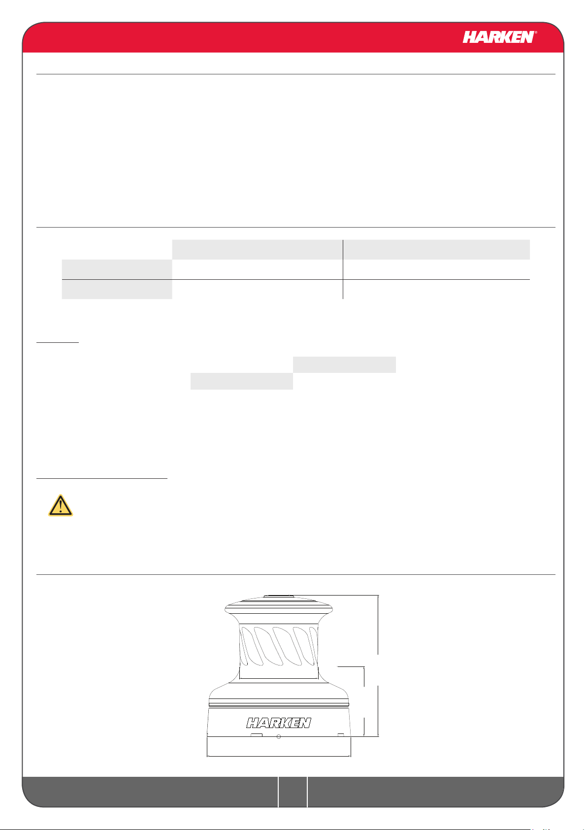
Outline
Radial Winch
46.2 PT
Ø101 mm
Ø184 mm
181 mm
90 mm
Line entry height
3
Installation and Maintenance Manual
Page 4
Installation
Installation
The winch must be installed on a at area of the deck, reinforced if necessary to bear a load equal
to at least twice the maximum working load of the winch.
It is the installer's responsibility to carry out all structural tests needed to ensure that the deck can
bear the load. Harken® does not supply the screws needed to install the winch since these may vary
depending on the deck on which it is to be installed.
It is the installer's responsibility to choose the correct screws taking account of the loads they will
have to bear. Harken® assumes no responsibility for incorrect installation of its winches or for an
incorrect choice of mounting screws.
DANGER!
Incorrect installation of the winch may cause severe injury or
death. Consult the yard that built the boat in the case of doubt
over the correct positioning of the winch.
WARNING!
Failure to use the correct number and type of mounting fasteners
or failure to ensure the correct deck strength can result in the
winch pulling off the deck suddenly and unexpectedly during
high loads causing severe injury or death.
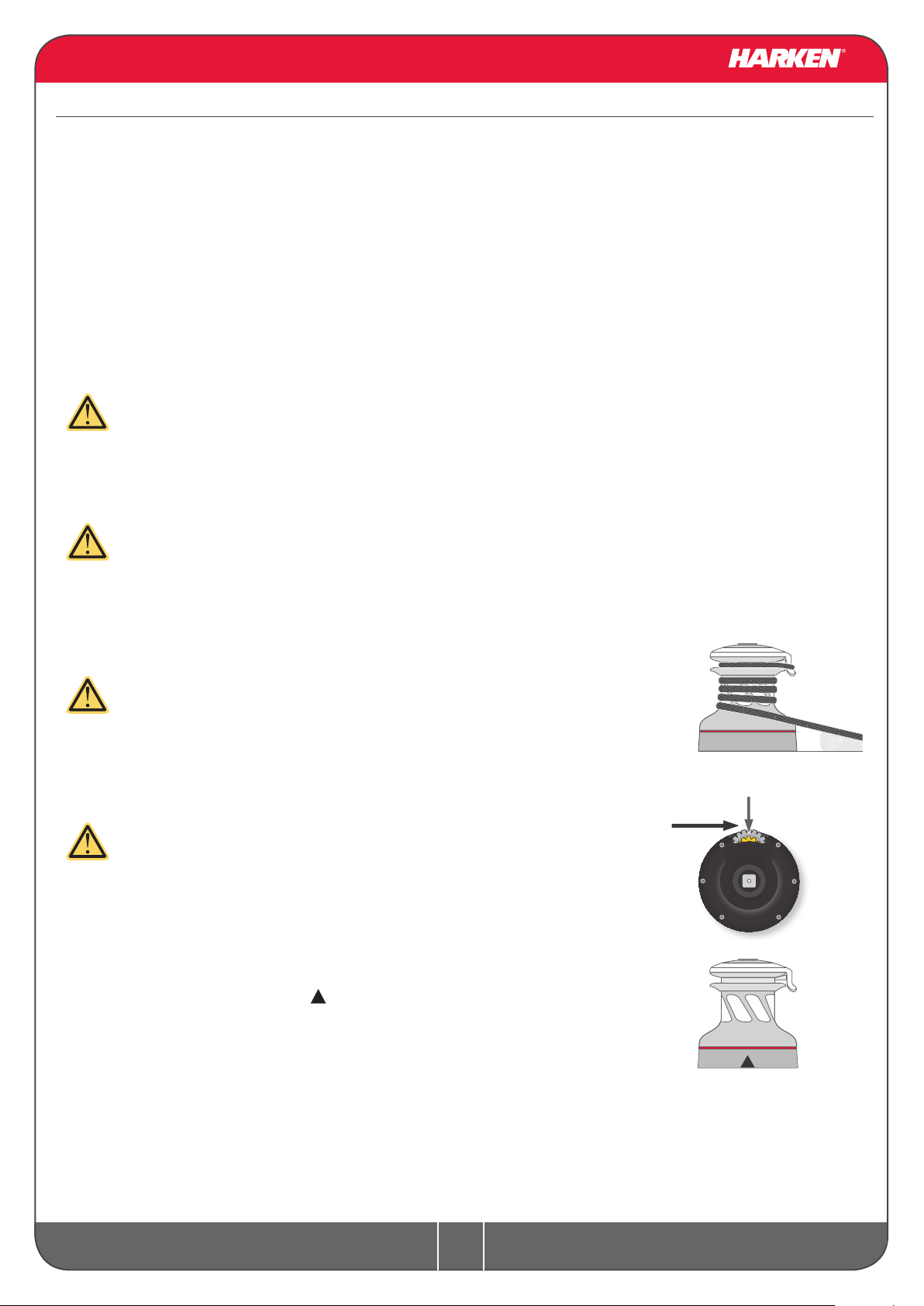
WARNING!
Verify the entry angle of the sheet. This must be 8° with tolerance
of ±2°, to avoid sheet overrides and damaging the winch or
making the winch inoperable leading to loss of control of the
boat which can lead to severe injury or death.
WARNING!
Mount the winch on the deck so that the drive gear is positioned
where the sheet enters the winch drum.
Incorrect position of drive gear can weaken winch leading to failure
which can cause an accident leading to severe injury or death.
NOTICE
You can find the icon on the skirt to identify the drive gear
position.
8°
drive gear
SHEET
Once you have chosen the correct mounting position for the winch on the deck proceed with
installation.
Radial Winch
46.2 PT
4
Installation and Maintenance Manual
Page 5
The winch can be installed following one of the two procedures below (Procedure1 or Procedure 2):
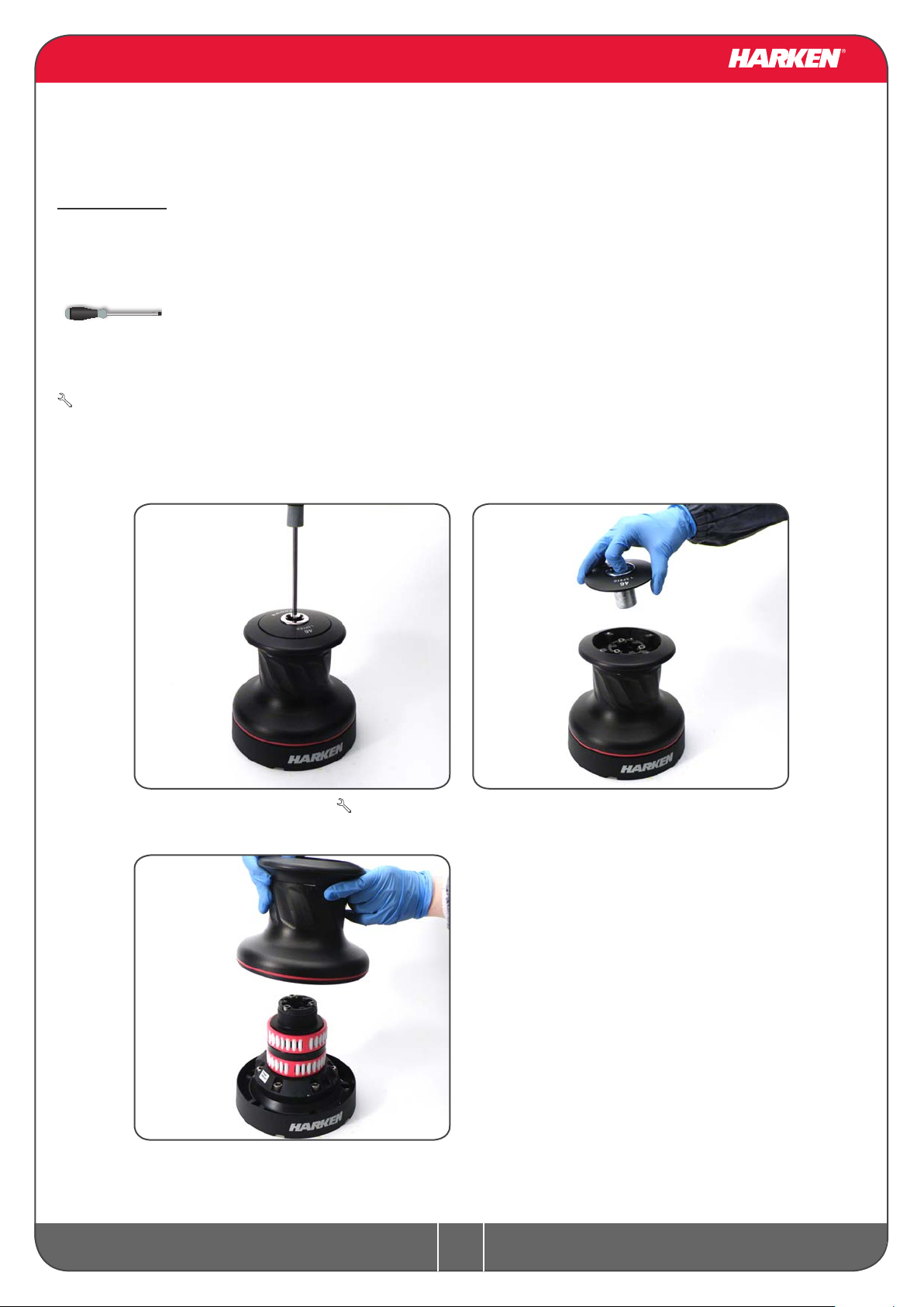
Procedure 1
To install the winch you must remove the drum and use Socket Head (SH) bolts.
Tools needed
One medium at-bladed screwdriver
To identify the various parts, refer to the exploded view at the end of this Manual.
Torque to apply when assembling
Install the winch on the deck in the position you have chosen, keeping in mind the limits described
on page 4 and using socket head (SH) bolts. (See paragraph on installation)
1. Unscrew the central screw ( 2Nm/18 in-lb)
3. Lift off the drum n°23
Radial Winch
46.2 PT
2. Slide off the assy socket n°30 and the
cover n°30
5
Installation and Maintenance Manual
Page 6

Procedure 2
To install, you must remove the winch skirt and use hexagonal headed bolts.
Tools needed
One medium at-bladed screwdriver
To identify the various parts, refer to the exploded view at the end of this Manual.
1. Remove the skirt n°2 with the help of the
screwdriver placed as shown by the symbol
3. Position the 5 M8 hexagonal headed
bolts in their holes
2. Take off the skirt n°2
Radial Winch
46.2 PT
6
Installation and Maintenance Manual
Page 7

4. Reposition the skirt n°2 in its housing 5. Press down the skirt to position it correctly
NOTICE
Make sure the skirt is correctly clipped on to the base of the winch.
Install the winch on the deck in the position you have chosen, keeping in mind the limits described
on page 4 and using hexagonal headed bolts. (See paragraph on installation)
Installation procedure
Carry out Procedure 1 or Procedure 2, then install the winch on the deck in the chosen position.
A. Position the base of the winch on the deck and mark the position of the holes or use the drilling
cut-out template at the point where you have decided to place the winch.
Below is a reduced scale diagram.
The drilling cut out template is available on the Harken® website, www.harken.com
Radial Winch
46.2 PT
7
Installation and Maintenance Manual
Page 8

Maintenance
B. Remove the winch and drill the ve 8.2 mm diameter holes.
C. Bolt the base of the winch to the deck using ve M8 Socket Head (SH) bolts for Procedure 1 or ve
hexagonal headed M8 bolts for Procedure 2 (neither is supplied by Harken®), correctly chosen for
the thickness and type of the boat deck. Consult the yard that built the boat in case of doubt.
WARNING!
To install the winch on the deck, use only bolts in A4 stainless steel (DIN 267 part11).
Bolts made of other materials may not have sufcient strength or may corrode which can
result in winch pulling off deck suddenly and unexpectedly during high loads causing
severe injury or death.
NOTICE
To mount winches on the deck, do not use countersunk bolts.
D. Fill the mounting holes with a suitable marine sealant.
E. Remove the excess adhesive/sealant from the holes and base drainage channels
F. Reassemble the winch following the steps in Procedure 1 or Procedure 2 in the reverse
order, and apply the products indicated in the section on maintenance.
NOTICE
Before closing the winch, make sure the holes and drainage channels in the base of the winch
are not obstructed.
Maintenance
Washing
Winches must be washed frequently with fresh water, and in any case after each use.
Do not allow teak cleaning products or other cleaners containing caustic solutions to come into
contact with winches and especially anodised, chrome plated or plastic parts.
Do not use solvents, polishes or abrasive pastes on the logos or stickers on the winches.
Make sure that the holes and drainage channels in the base of the winch are not obstructed so that
water does not collect.
Maintenance table
Winches must be visually inspected at the beginning and end of every season of sailing or racing.
In addition they must be completely overhauled, cleaned and lubricated at least every 12 months.
After an inspection, replace worn or damaged components. Do not replace or modify any part of the
winch with a part that is not original.
Radial Winch
46.2 PT
8
Installation and Maintenance Manual
Page 9

WARNING!
Periodic maintenance must be carried out regularly. Lack of adequate maintenance
shortens the life of the winch, can cause serious injury and also invalidate the winch
warranty. Installation and maintenance of winches must be carried out exclusively by
specialized personnel.
®
In the case of doubt contact Harken
Tech Service at techservice@harken.it
Disassembly procedure
Tools needed
One medium at-bladed screwdriver
A number six hex key
Rags
To identify the various parts refer to the exploded view at the end of this Manual.
Torque to be applied in assembly phase
Carry out Procedure 1 as shown in the paragraph on winch installation and then do the following:
4. Completely unscrew the three screws n° 27
and remove the socket support n°22
6. Unscrew the 6 hex screws n°17
Radial Winch
46.2 PT
5. Slide out the central shaft n°20
7. Remove the assy housing n°16
Important: washer n°13 may remain
inside the drum support!
9
Installation and Maintenance Manual
Page 10

8. Remove the gear n° 15
10. Remove the gearing n°10 and remove the
pawls n° 7
9. Remove the washer n°13
To facilitate the operation press the spring
against the pawl with a blade.
11. Slide off gear n°3
Radial Winch
46.2 PT
12. Remove the pinion n°11
To facilitate the operation press the spring
against the pawl with a blade
10
Installation and Maintenance Manual
Page 11

13. Remove the gear n° 6 14. Remove the washer n°5
Once the winch is completely disassembled, clean the parts: use a basin of diesel oil to soak
metal components and rinse plastic parts in fresh water. Once you have done this, dry the parts
with cloths that do not leave residue.
Inspect gears, bearings, pins and pawls for any signs of wear or corrosion.
Carefully check the teeth of gears and ring gears to make sure there are no traces of wear.
Check the roller bearings and check there are no breaks in the bearing cages.
Replace worn or damaged components.
Carry out maintenance on components using the products listed below.
For more information on which products to use where, refer to the exploded diagram below.
Use a brush to lightly lubricate all gears, gear pins, teeth and all moving parts with grease.
Lightly lubricate the pawls and springs with oil. Do not use grease on the pawls!
Radial Winch
46.2 PT
11
Installation and Maintenance Manual
Page 12

Exploded view with maintenance products
1
G
G
A
A
Anti-seize
A
Harken® Grease
G
Harken® Pawl Oil
O
G
A
G
A
G
G
G
O
G
G
G
2
O
G
G
3
G
Radial Winch
46.2 PT
1
Apply Harken® grease on assy socket screw
2
Apply Harken® grease on drum gear
3
Apply Harken® grease on the middle step of assy housing
12
Installation and Maintenance Manual
Page 13

Harken® limited worldwide warranty - Ordering spare parts
Assembly
Make sure that the holes and drainage channels in the base of the winch are not obstructed
Assemble the winch in the reverse order of the sequence in the section on disassembly.
To tighten bolts, use the torque indicated in the disassembly procedure.
To assemble the pawls:
correctly position the spring in its housing as
OIL
shown at left. Hold the spring closed and slide
the pawl into its housing. Once in position,
check that the pawls can be easily opened and
closed with a nger.
In case of doubt concerning the assembly procedure contact Harken
®
Tech Service: techservice@harken.it
Harken® limited worldwide warranty
Refer to the Harken® Limited Worldwide Warranty in the Harken® Catalogue and on the website
www.harken.com
Ordering spare parts
Spare parts can be requested from Harken® as
described in the Harken® Limited Worldwide
Warranty, indicating the part number in the
Parts List and including the serial number of
the winch for which the parts are required.
W XXXXX
XXXXXXXXX
The serial number of the winch is printed on
a plate on the drum support of the winch.
Radial Winch
46.2 PT
13
Installation and Maintenance Manual
Page 14

Manufacturer
Harken® Italy S.p.A.
Via Marco Biagi, 14
22070 Limido Comasco (CO) Italy
Tel: (+39) 031.3523511
Fax: (+39) 031.3520031
Email: info@harken.it
Web: www.harken.com
Headquarters
Harken®, Inc.
1251 East Wisconsin Avenue
Pewaukee, Wisconsin 53072-3755 USA
Tel: (262) 691.3320
Fax: (262) 691.3008
Email: harken@harken.com
Web: www.harken.com
Tech Service
Email: techservice@harken.it
Customer Service
Tel: (+39) 031.3523511
Email: info@harken.it
Tech Service
Email: technicalservice@harken.com
Customer Service
Tel: (262) 691-3320
Email: customerservice@harken.com
Radial Winch
46.2 PT
14
Installation and Maintenance Manual
Page 15

Exploded view 1/2
20
13
10
8
9
7
14
4
12
12
11
9
8
6
15
5
3
1
2
Radial Winch
46.2 PT
15
Installation and Maintenance Manual
Page 16

Exploded view 2/2
30
31
23
29
21
24
18
19
18
16
17
27
22
26
28
25
28
Radial Winch
46.2 PT
16
Installation and Maintenance Manual
Page 17

Parts list
Radial Winch 46.2 PTA
A= drum in anodised aluminium
Pos. Q.ty Code
1 1 A 941321 00
2 1 A 941323 00
3 1 S 41302 00 04 Gear Z12
4 1 S 41330 00 04
5 1 S278170002
6 1 S 41326 00 04 Gear Z27
7 1 S 41426 00 04
8 6 S 00008 00 03
9 6 S 00038 00 01
10 1 S 41283 00 41 Gear Z23
11 1 S 41325 00 41
12 2 M6017694
13 1 S 41312 00 02
14 1 S 41307 00 04
15 1 A 941334 00 Assy Gear Z12
16 1 A 941322 00
17 5 M0643203
18 2 A 741337 00
19 1 S 41339 00 80 Spacer
20 1 A94189400
21 1 S 41876 00 63
22 1 S 41514 00 A0 Socket Support PT
23 1 S 41272 00 53 Drum W46
24 1 S281690097
25 1 S 41620 00 53
26 4 M 06037 03 Screw M6x12 UNI 5931*
27 3 M0600903 Screw M6x20 UNI5931*
28 47 M0619580
29 1 S 41619 00 53 Cover W46 PT
30 1 A94136400
Description
Assy Base Winch 46
Winch Serial Number Sticker
Assy Skirt Winch 46**
Pin ø12x60
Washer 12.5x48x1.5*
Pawls Carrier Ø8xN2
Pawl Ø8*
Pawl Spring Ø8*
Pinion Z13
IGUS Bushing PSM-1214-20*
Washer Ø22.5xØ45x1*
Pin ø9-ø12x32.5
Assy Housing Winch 46
Screw M8x20 UNI5931*
Bearing Ø75xØ87x26*
Assy Central Shaft Winch 46
Winch Serial Number Sticker
Red line
Plain Top W46
Ball 3/16" *
Assy - Socket W20-80
Screw M8x20 UNI 6109*
Washer Ø7.7xØ25x5.8
Socket Handle W20/80
Radial Winch
31 1 S 41522 00 80 PT spacer
*Service kit available; see winch kit section on the website www.harken.com
**Winch product sticker
46.2 PT
17
Installation and Maintenance Manual
 Loading...