

Page 1
INSTALLATION SHEET
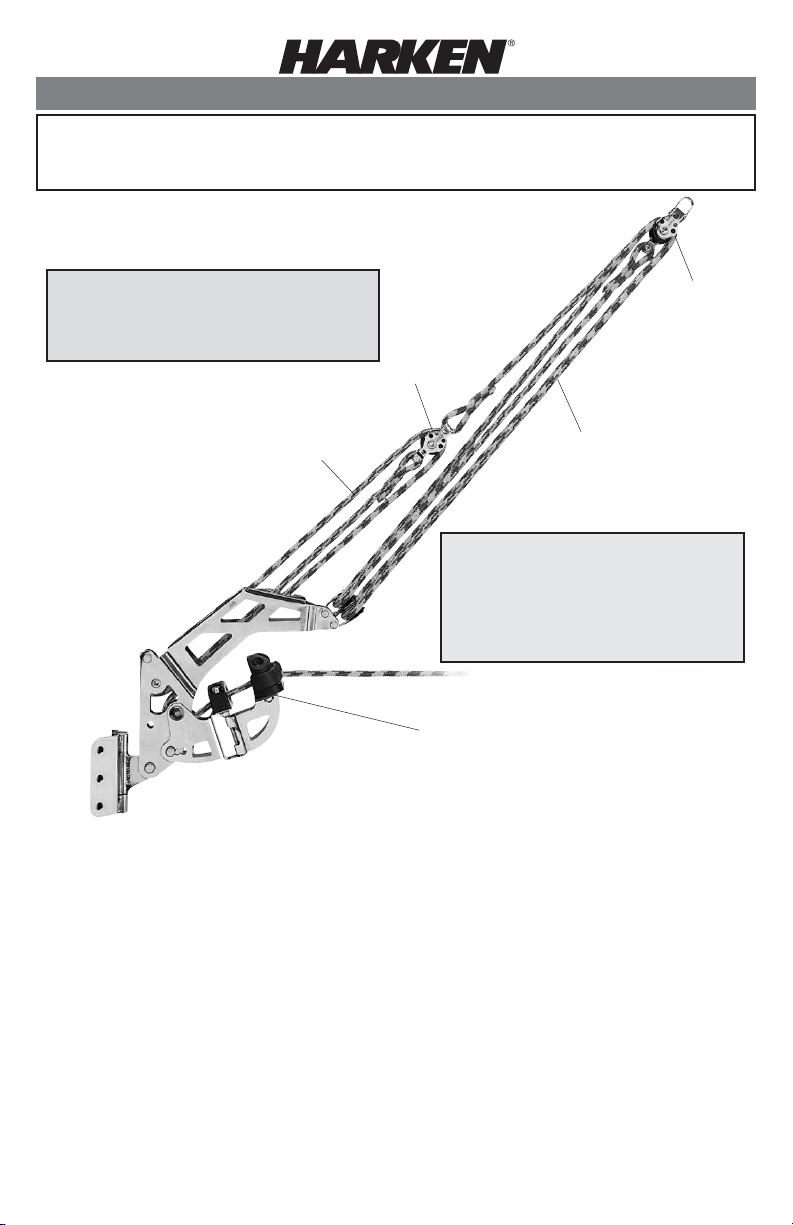
15:1 Power Dinghy Vang
447 (System) or 455 (Lower Assembly)
N15W24983 Bluemound Road • Pewaukee, WI 53072 U.S.A.
Telephone: (262) 691-3320 • Fax: (262) 701-5780
Web: www.harken.com • Email: harken@harken.com
Max working load = 450 lb (204 kg)
Breaking load = 1200 lb (544 kg)
Max sail area = 125 ft2 (11.6 m)
Lower line
(5 mm)
Parts included (447 only)
Lower assembly
16mm AirBlock
Upper block 16 mm AirBlock
Upper Line: 10' of 3mm polyester line
Lower Line: 10' of 5mm polyester line
®
405
®
w/becket #407
Tools you must supply
Drill motor
5/32" (4 mm) drill bit (for screws)
10-32 (5 x .80 mm) tap (for screws)
Screw driver (for screws)
3/16" (5mm) drill bit (if pop rivets are used)
Pop rivet gun (optional)
Centerpunch
Pencil or fine-point marker
407
405
Upper line
(3 mm)
The enclosed vang is not for use on the
Laser. The Laser vang is a different part
and is only available through Laser
builders or their dealers. Please contact
your Laser dealer regarding availability.
Lower assembly
(455 if purchased separately)
Parts you must supply
10-32 (5x .80 mm) stainless steel screws
(optional)
– or –
3/16" (5 mm) stainless steel pop rivets
Use shackle (246) if there is a bail or strap
to attach upper block to boom.
Use eyestrap (073) if there is no bail on
boom.
Page 2

Part 1 – Reeving Line
Note: The following section is for replacing line on the 447 system, or
assembling if you purchased the 455 separately. If you purchased the
Dinghy Vang system 447, line is pre-reeved. Skip to Part 2: Mounting
Instructions.
Line replacement chart
Length AB 14" 16" 18" 20" 22" 24" 26" 28" 30" 32" 34" 36"
3:1 28" 32" 36" 40" 44" 48" 52" 56" 60" 64" 68" 72"
5:1 28" 37" 46" 54" 63" 72" 80" 89" 98" 106" 115" 124"
Typically 3:1 is the heavier line that exits from cam. 5:1 is the lighter, gross trim line. Line Lengths
are close, but add extra for adjustments on individual boat. Be sure to add extra line to the 3:1 to
accommodate the distance from vang fitting to helm.
Lower assembly
Tie off one end of 5 mm line on becket of 405 block. Pull line through front of lower assembly,
around top sheave from the bottom. Pull line back out of lower assembly, around sheave of 405
block from the top, and back into lower assembly. Then wrap around lower sheave from the top,
and pull line out through bullseye and cam.
Start here
A
Length from
base of mast
to boom
attachment
B
Upper block
Fig. 1
A
407
1. Tie off one end of
3 mm line around head
of 405 block. Pull line
up around becket side
sheave of 407 block,
and down around
sheave A on end of
lower assembly as
shown.
Start
here
405
Continues on Fig. 2
B
End of lower
assembly
A
continue
from here
A
Fig. 2
End
here
B
407
2. Pull line back up from
back side of sheave A on
end of lower assembly,
around top of the back
sheave of 407 block. Then
pull line down around
sheave B on end of lower
assembly. Then bring line
back up to becket of 407
block and tie off.
405
B
End of lower
assembly
405
Page 3

Part 2 – Mounting Instructions
Mounting options
Mount the Dinghy Vang with either stainless steel pop rivets or with screws into a threaded hole.
Pop riveting is easier and quicker, but it is essential to use stainless steel pop rivets. Other types
of pop rivets are not strong enough. When using screws it is important to have properly drilled
holes with correctly tapped threads.
Boom Attachment: Some boats may already have a bail or other attachment point on the boom.
In this case attach the 405 block to the boom with a shackle. If there are no attachment points,
attach the 405 block with an eyestrap or bail.
General Instructions: Locating & Mounting
1. Locating the vang attachment points:
Lower Assembly: The vang is the most efficient when
the lower assembly is mounted as low as possible without
interference from deck or other hardware. Attaching it to
the mastbase is best.
Upper 16mm Block: Mount the upper block about 1/3
of the way back from the mast. The ideal vang angle
is about 30° from the deck.
30°
2. Mounting the Lower Assembly:
Position lower stainless steel bracket
and mark the 6 holes on the mast.
Use the center punch to make a dimple
at the marked hole position.
Drill holes accordingly for either #10-32
stainless screws or 3/16" stainless pop rivets.
too much
gap
Note: If bracket does not fit mast, put it in a vice and squeeze slightly to fit.
continued on back
Page 4

Mount the bracket to the mast using:
#10 Screws: Stainless
Recommended 10-32 (5 x .80 mm) screws
Drill 5/32(4 mm) for tapping
Tap with a 10-32 (5 x .80 mm) tap
or
Pop Rivet: Stainless
Recommended 3/16" (5 mm)
3/16" (5 mm) drill bit
3. Mount the upper double block:
Bail Option:
Attach double 16 mm block to the bail with a
246 shackle.
Eyestrap Option:
Locate eyestrap about 1/3rd of the way down
boom. Mark eyestrap hole location. Before
mounting, slip #407 block over eyestrap.
Mount using lower assembly instructions.
Adjust the length to fit your boat by untying knot
at the upper block (407) on boom at the becket
and pulling extra line to desired length. Retie knot
in new position.
Cam Arm Adjustment
The cam arm angle can be adjusted to 3 positions
to suit sailor's preferred line lead.
1. Remove keeper ring and clevis pin from
lower part of cam arm on lower assembly.
2. Raise or lower arm as desired.
3. Replace clevis pin and ring.
Position 1
Position 2
Position 3
Maintenance
Harken equipment requires minimal maintenance, but some is required to give the best service and to
comply with Harken's limited warranty.
It is important to keep equipment clean by frequently flushing with fresh water. In corrosive
atmospheres, stainless parts may show discoloration around holes, rivets and screws. This is not
serious and may be removed with a fine abrasive.
With the exception of winches, do not use grease unless specifically recommended in the instruction
sheets.
IMPORTANT! Exposure to some teak cleaners and other caustic solutions can result in discoloration
of part and is not covered under the Harken warranty.
Warranty
See the Harken catalog or www.harken.com/manuals for additional maintenance and warranty information.
Printed in USA. 4928 04/14
 Loading...