

Page 1
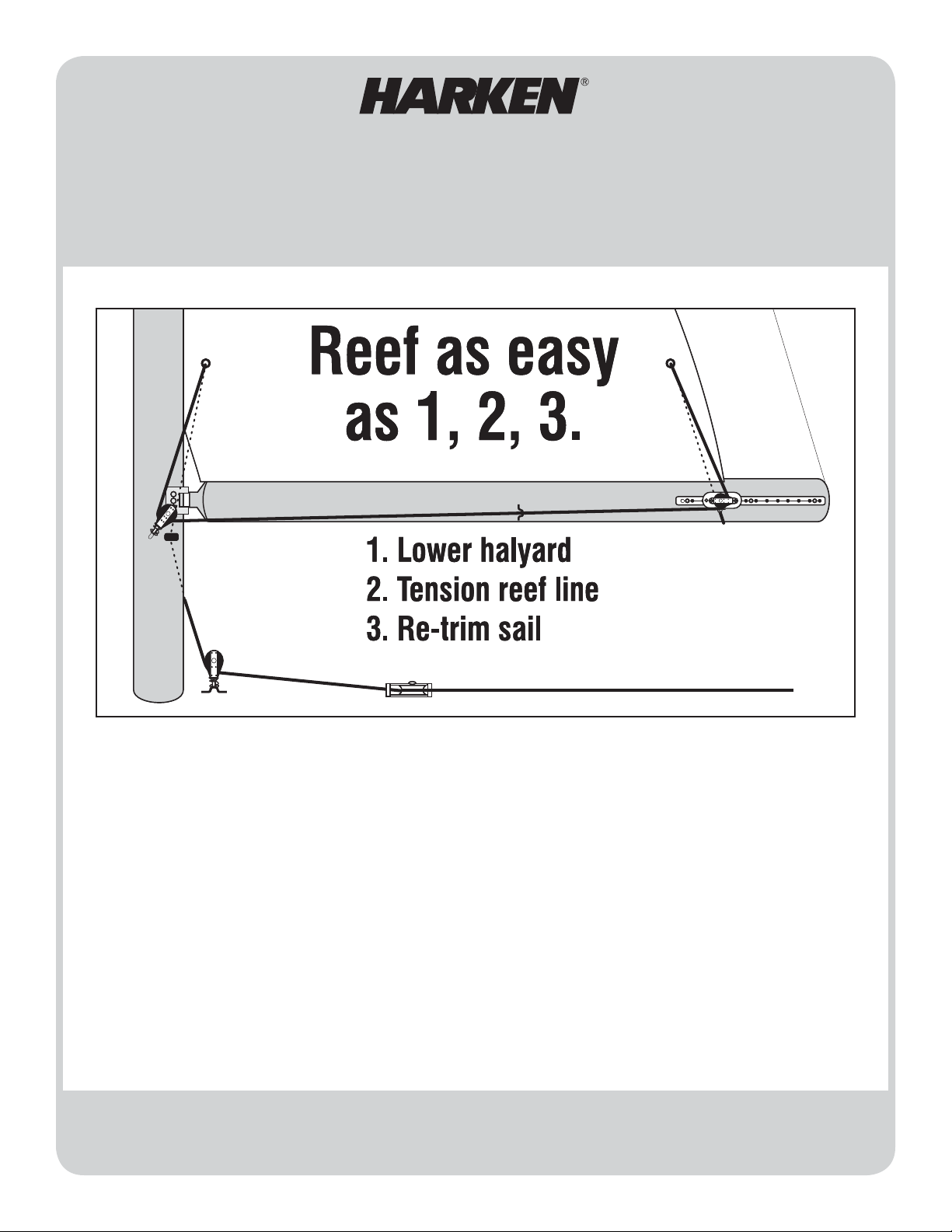
SINGLE LINE MAINSAIL REEFING SYSTEM
430
(For boats 22 - 27 ft (6 - 8 m) with mainsails under 150 ft
Installation Manual – Intended for specialized personnel or expert users
2
(14 m2)
4171 12/13
Reef Mainsail with One Line
Easy to Install
Reef From Cockpit in Seconds
Use with Regular or Full-Length Battens
Track Allows Easy Adjustment of Block for Best Sail Shape
No Modification to Sails with Reef Points
Please read these instructions carefully before installing, servicing, or operating the equipment.
This manual may be modified without notice. See: www.harken.com/manuals for updated versions.
PLEASE SAVE THESE INSTRUCTIONS
Page 2

Parts (Included) Drill/Tap Sets You Must Supply
Clew Track Assembly
1 HSB60 Clew Slider Assembly
1 H-24294C Track
1 833 Blue Loctite® (Threadlocker 242)
6 HFS566 5/16-18 x 3/4” Flathead Screws (1 Extra)
6 HFS841 M8 x 1.25 x 20 mm Flathead Screws (1 Extra)
Mid-Boom Fairlead
1 137 Eyestrap
3 HFS104 #10-32 x 3/8” Trusshead Screws (1 Extra)
3 HFS842 M5 x .80 x 10 mm Panhead Screws (1 Extra)
3 HFS125 #10 x 3/8” Self-Tapping Panhead Screws (1 Extra)
Mast Mounted Tack Block Assembly
1 168 Big Bullet Block/071 Spring/137 Eyestrap
2 HFS104 10-32 x 3/8” Trusshead Screws
2 HFS842 M5 x .80 x 10 mm Panhead Screws
2 HFS125 #10 X 3/8” Self-Tapping Panhead Screws
Mast Mounted Bullseye
1 H-24675A Bullseye
3 HFS259 10-32 x 11/4” Roundhead Screws (1 Extra)
3 HFS843 M5 x .80 x 30 mm Panhead Screws (1 Extra)
3 HFS840 #10 x 11/4” Self-Tapping Screws (1 Extra)
Deck Blocks
1 132 Big Bullet Cheek Block
1 168 Big Bullet Block/071 Spring/137 Eyestrap
5 HFS106 10-32 x 1-1/2” Roundhead Screws (1 Extra)
5 HFS110 10-32 18-8 Nuts (1 Extra)
5 HFS111 Washer (1 Extra)
5 HFS112 Lockwasher (1 Extra)
Tools You Must Supply
Electric Drill
Drill Bits
Screwdrivers
Slotted
Phillips
Wrench – 3/8” (9.5 mm) or Adjustable
Hammer
Center Punch
Pencil or Fine Point Marker
US Drill Bits
5/32” for 10-32 Tap Set and for Self-Tapping #10 Screws
13/64” for Deck Clearance Holes for #10 Screws*
17/64” for 5/16-18 Tap Set
*Used for mounting mast base block to deck, not used if shackling to mast
collar. Also used for deflector block, not used if using deck organizer.
US Tap Sets
10-32 optional - you can also use self-tapping screws
5/16-18 required for mounting track
Metric Drill Bits
4 mm
for 10-32 Self-Tapping Screws
5 mm for Deck Clearance Holes for #10 Screws*
4.2 mm for 5 x .80 mm Tap Set (Optional)
6.8 mm for 8 x 1.25 mm Tap Set
*Used for mounting mast base block to deck, not used if shackling to mast
collar. Also used for deflector block, not used if using deck organizer.
Metric Tap Sets
5 x .80 mm
8 x 1.25 mm
Optional-you can also use self-tapping screws
Required for mounting track
Parts You Must Supply
• Reefing line – 5/16” (8mm) double braided Dacron
line. Use formula below to calculate length.
• Cleat or stopper to secure reefing line.
• High quality marine sealant for mounting deck
hardware.
• Back-up plate or large diameter washers for
backing up deck hardware screws.
• Topping lift.
• For most effective reefing, the main halyard
should be led back to the cockpit.
• Feeder cover plates for grooved spar so sail
slugs can pass mast feeder gap. See the bottom
of page 7.
Figuring Line Length
1 Reef height X 5 ................. ____________
2 Sail foot length X 2.............. ____________
3 Add 7 feet (2.2 m) ..............+ 7 feet (2.2 m)
Total length of reefing line.......... ____________
Sail Work
In most cases your mainsail needs no alteration. Check
to make sure your sail is fitted with tack and clew reef
grommets. Intermediate reef points are used
as required.
2
Page 3
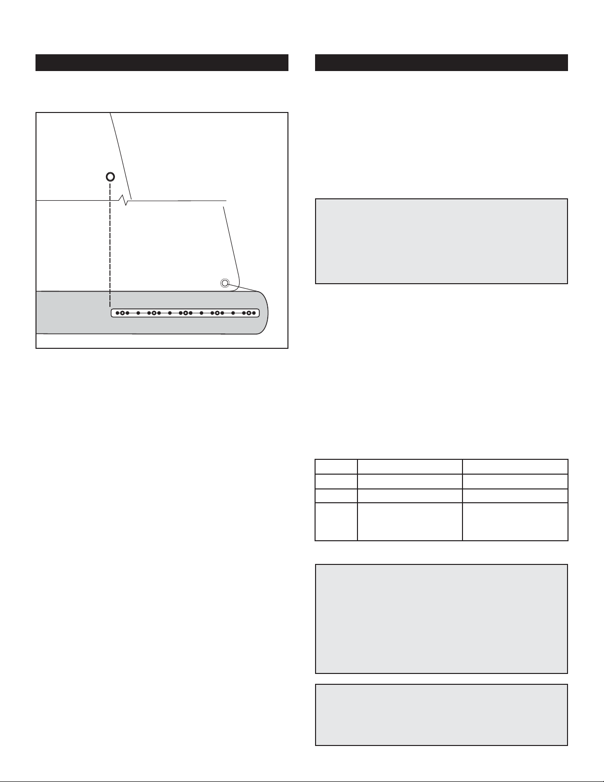
Step 1 Mounting Track on Boom
General Instructions Detailed Instructions
A. Decide whether to place the system on the port or
starboard side of the boom.
B. Mount track at the aft end of the boom.
A. Each boat is different. Choose the best side by deter-
mining if you have room on the boom and where the
line will lead on the cabin house. Remember, the line
runs down the opposite side of the mast as the track is
mounted to the boom. If the track is on starboard, the
line will run down the port side of the cabin top. You
will need 19” (483 mm) on the aft end of the boom to
mount the track.
Installation Tip – Plan the Location of All Hardware
Before Installation
Look at the mast area to see if the tack block and bullseye will
fit easily. Look at the mast base area. Is there a good spot for
mounting the mast base block? Where is the main halyard cleat?
If possible, locate the single line cleat near the halyard cleat in
easy reach of the cockpit.
B. Place the track so the front edge is behind the aft
mainsail reefing grommet. If the boom is not long
enough for this, position the track as far aft as
possible.
Carefully mark the holes, drill, tap and mount track.
See tips below.
US Metric
Drill
Tap
5 Screws
(Use Blue Loctite on Screws)
Installation Tip – Lining Up Holes with Track
If holes in boom do not line up with track holes, it will be very
difficult to install screws. After marking each hole, drill and tap
the forward hole and use a screw to secure the track. Use a center punch to start the other holes. If any dimples do not line up,
relocate them before drilling holes. Loosen screw and let track
pivot out of the way and drill the other holes. Do not drill holes
through track; remove track before drilling.
Installation Tip – Drilling
Hold the drill perpendicular to the face of the boom. Do not angle
the drill or it will be very difficult to install the screws flush with
the track.
3
17/64” 6.8 mm
5/16-18 8 x 1.25 mm
5/16 -18 x 3/4”
Flathead Machine Screws
Flathead Machine Screws
(Use Blue Loctite on Screws)
8 x 1.25 x 20 mm
Page 4

Step 2 Mounting Clew Slider
General Instructions Detailed Instructions
A. Install the clew slider on the track, so it’s aft of the
reef outhaul grommet.
Starboard Installation
Port Installation
Port-Side Installation
If installing on port side, flip block around.
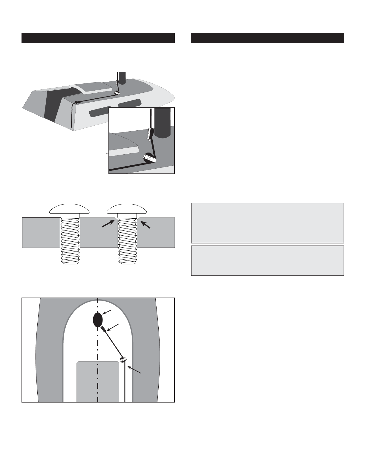
Step 3 Installing Tack Block
General Instructions Detailed Instructions
A. Load the clew slider on the track so the eyestrap
is down. Secure by tightening the set screw into a
positioning hole. This may be adjusted later while
adjusting the system at the dock with the sail hoisted.
Port-Side Installation
The car is shipped ready for installation on the starboard side. If installing on the port side of the boom
remove the cheek block and reinstall so sheave faces
forward.
A. Mount the reefing tack block to the mast on the same
side as the track is mounted to the boom. Position the
block so the line pulls down and forward at 45° when
reefed.
Mast
7:oo
5:oo
A. Choose the same side as the track is mounted to
the boom. Position the reefing tack block so it’s aft of
the side of the mast. Looking down from above it will
be pointed to 5:00 or 7:00 o’clock depending whether
it’s mounted on the starboard or port side respectively.
Looking from the side, the top of the block should be
just below the level of the bottom of the boom. Position
the eyestrap, parallel to the load (see diagram).
Self-Tapping
US Metric
Drill
2 Screws
Drill
Tap
2 Screws
#10 x 3/8”
Roundhead Self-Tapping Screws
(Use Blue Loctite on Screws)
Drilling and Tapping
10-32 x 3/8”
Roundhead Machine Screws
(Use Blue Loctite on Screws)
Trusshead Machine Screws
(Use Blue Loctite on Screws)
4 mm5/32”
MetricUS
4.2 mm5/32”
5 x .80 mm10-32
5 x .80 x 10 mm
Position the
eyestrap so it
aligns with
the load.
Installation Tip – Internal Halyards
To keep screw from snagging internal halyards, first install, then
remove, nip off the end and reinstall.
4
Page 5

Step 4: Installing Tack Bullseye
General Instructions Detailed Instructions
A. Mount the reefing tack bullseye so it is on the opposite
side from the tack block. Position the bullseye so the line
pulls down and forward at 45° when reefed.
Mast
7:oo
5:oo
A. Position the reefing tack bullseye so it is on the
opposite side from the tack block. Looking down from
above it will be pointed to 7:00 or 5:00 o’clock depending whether it’s mounted on the port or starboard side
respectively. Looking from the side, the bullseye should
be just below the level of the bottom of the boom.
Position the bullseye so the mounting holes run side
to side.
Self-Tapping
US Metric
Drill
#10 x 1-1/4”
2 Screws
Drill
Tap
10-32 x 1-1/4”
2 Screws
Installation Tip – Internal Halyards
To keep screw from snagging internal halyards, first install, then
remove, nip off the end and reinstall.
Roundhead Screws
(Use Blue Loctite on Screws)
Roundhead Screws
(Use Blue Loctite on Screws)
Drilling and Tapping
Trusshead Machine Screws
(Use Blue Loctite on Screws)
4 mm5/32”
MetricUS
4.2 mm5/32”
5 x .80 mm10-32
5 x .80 x 30 mm
Step 5 Installing Mid-Boom Fairlead Eyestrap
General Instructions Detailed Instructions
A. Install the eyestrap half way between the clew slider
and the mast.
Halfway
Keep friction to a minimum,
by positioning eyestrap
so reefing line will lead
smoothly to tack block.
A. The eyestrap is used to help hold the reefing line
from drooping when it is not tensioned.
Position the eyestrap so the reefing line runs directly
through the eyestrap as it runs from the clew slider to
the mast. Choose one of the mounting methods below
and install.
Self-Tapping
Metric
4 mm
MetricUS
4.2 mm5/32”
5 x .80 mm10-32
5 x .80 x 10 mm
Drill
2 Screws
Drill
Tap
2 Screws
US
5/32”
#10 x 3/8”
Roundhead Self-Tapping Screws
(Use Blue Loctite on Screws)
Drilling and Tapping
10-32 x 3/8”
Roundhead Machine Screws
(Use Blue Loctite on Screws)
Trusshead Machine Screws
(Use Blue Loctite on Screws)
Installation Tip – Internal Halyards
To keep screw from snagging internal halyards, first install, then
remove, nip off the end and reinstall.
5
Page 6
Step 6 Installing Deck Hardware
General Instructions Detailed Instructions
A. Mount mast base block directly below the bullseye
and position so block is angled towards the deflector
block or deck organizer.
Mount so it bisects
line angle and is aft
and inboard to reduce
load on block.
Beveling Top Edge of Hole
Deck
A. If there is a mast collar, remove the eyestrap and
shackle the block to the collar. Alternatively, install the
block with eyestrap to the deck.
Position the eyestrap on the deck below the bullseye.
Align the legs of the eyestrap so they are in line with
the line direction to the deflector block or deck organizer. Consider the location of the back-up nuts below
deck when planning the block’s location of the mast
base block. See tip below.
Drill holes and apply a high quality marine sealant to
the holes. See tip below. Install the block assembly. Use
a back-up plate or large diameter washers inside the
cabin top to back up the hardware.
Drill size - 13/64” (5mm)
Mounting Hardware
2 10-32 X 11/2” Roundhead screws
2 Washers
2 Lockwashers
2 10-32 Nuts
Marine Sealant – Use to seal holes - See tip below.
Installation Tip – Planning Location of Deck Hardware
It is important to plan the location of all deck hardware before
mounting the mastbase block, deflector block and cleat. The
position of one block depends on the location of the other block
or cleat. In addition, you must consider the location and
accessibility of back up hardware inside the cabin top.
Before After
B. Install deflector block so line runs in fore/aft direction
to cleat.
Mast
Mast base
block
Keep
block aft
C. Install cleat or line stopper at a convenient spot on
the cabin top near the main halyard cleat.
Installation Tip – Beveling Top Edge of Hole
After drilling through deck, slightly round off the top edge of the
holes with a small knife. This way, when the sealant is applied, it
will mass around the screw providing a good durable water seal.
B. The deflector block is used to turn the reefing line so
it does not interfere with the companionway hatch or
other obstructions on the cabin top:
1) Place so line runs in straight fore/aft direction to cleat.
2) Keep block aft and inboard to reduce load.
3) Check for suitable position for back-up nut and washers.
4) Rotate so it bisects line angle.
Drill holes, apply marine sealant and install using:
Drill size - 13/64” (5mm)
Mounting Hardware
2 10-32 X 11/2” Roundhead screws
2 Washers
2 Lockwashers
2 10-32 Nuts
Marine sealant – Use to seal holes.
C. You will need to supply a cleat or line stopper for
the Single Line Reefing system and hardware to mount
it. Mount the cleat in a convenient spot within easy
reach of the cockpit, near the main halyard cleat if possible. Make sure the cleat or line stopper is throughbolted and has a suitable back-up plate or washers.
6
Page 7

Step 7 Reeving the Control Line
General Instructions Detailed Instructions
A. Hoist the mainsail.
B. Starting at the eyestrap at the clew slider reeve the
line through the sail and blocks.
6
5
7
8
9
4
2
3
1
10
Step 8 Adjust Clew Car
General Instructions Detailed Instructions
A. Adjust the clew car to find optimum sail shape.
Mark halyard.
Topping Lift
B. You need to supply 5/16” (8 mm) double braided
Dacron line in a length as determined in the formula
on page 2:
1) Tie or splice line end to eyestrap on clew slider.
2) With sail hoisted, run line under the boom and up
through reefing grommet at clew.
3) Lead down through the block on clew slider.
4) Run line forward through eyestrap on boom.
5) Lead line up through big bullet block on mast.
6) Then up through the reefing tack grommet.
7) Down through bullseye on other side of mast.
8) Through the mast base big bullet block.
9) Through deflector block.
10) Back to cleat.
A. With the sail raised, move the clew slider to find the
optimum sail shape. Try reefing the system. The clew
line should pull down and aft at a 30 to 45° angle. It
is important to have a topping lift when reefing to prevent the boom from dropping down into the boat when
the halyard is eased.
Step 9 Reef
General Instructions Detailed Instructions
A. To reef, set the topping lift, ease the halyard, pull the
reef line, and tension the halyard if necessary. Test the
system before you need to use it.
Reefing Tip – Marking the Halyard
Mark the halyard so you know how far to ease it when lowering
the main in preparation for reefing. Start with the sail reefed and
the halyard tensioned. Mark the halyard at the cleat using a permanent marker. When reefing the sail, set the topping life, lower
the halyard to the mark and pull the reef line, and tension the
halyard if necessary.
A. Make sure the topping lift is set. Ease the halyard to
the mark that you have made and cleat it. Pull the reef
line until the clew and tack are down near the boom.
Keep pulling until the foot of the sail is tight and cleat
the reefing line. Check to make sure you can lower
slugs far enough to reef. Do not use stop above feeder
gap. Mount feeder plates so slugs pass below feeder.
Feeder plates are available from spar makers and are
screwed into the mast on either side of the feeder.
7
Page 8

Corporate Headquarters
N15W24983 Bluemound Rd, Pewaukee, WI 53072 USA
Telephone: (262) 691-3320 • Fax: (262) 701-5780
Web: www.harken.com • Online Catalog: www.harkenstore.com
1B Green Street, Brookvale, N.S.W. 2100, Australia
Telephone: (61) 2-8978-8666 • Fax: (61) 2-8978-8667
Web: harken.com.au • Email: info@harken.com.au
ZA Port des Minimes, BP 3064, 17032 La Rochelle Cedex 1, France
Telephone: (33) 05.46.44.51.20 • Fax: (33) 05.46.44.25.70
Via Marco Biagi, 14, 22070 Limido Comasco (CO) Italy
Telephone: (39) 031.3523511 • Fax: (39) 031.3520031
30-36 Fanshawe Street, P.O. Box 1951, Auckland 1001, New Zealand
Telephone: (64) 9-303-3744 • Fax: (64) 9-307-7987
Web: harken.co.nz • Email: harken@harken.co.nz
ul. Rydygiera 8, budynek 3A, lokal 101, I pi
Tel: +48 22 561 93 93 • Fax: +48 22 839 22 75
Main Office and Harken Brandstore: Västmannagatan 81B
Telephone: (46) 0303 61875 • Fax: (46) 0303 61876
Mailing address: Harken Sweden AB, Box 64, SE -440 30 Marstrand
Bearing House, Ampress Lane, Lymington, Hampshire S041 8LW, England
Telephone: (44) 01590-689122 • Fax: (44) 01590-610274
Web: harken.co.uk • Email: enquiries@harken.co.uk
Email: harken@harken.com
Harken Australia Pty, Ltd.
Harken France
Web: harken.fr • Email: info@harken.fr
Harken Italy S.p.A.
Web: harken.it • Email: info@harken.it
Harken New Zealand, Ltd.
Harken Polska SP ZOO
ętro, 01-793 Warszawa, Poland
Web: harken.pl • Email: polska@harken.pl
Harken Sweden AB
SE-113 26 Stockholm Sweden
Web: harken.se • Email: harken@harken.se
Harken UK, Ltd.
Please visit: http://www.harken.com/locator.aspx
to locate Harken dealers and distributors
Printed in USA 4171 12/13
 Loading...