

Page 1
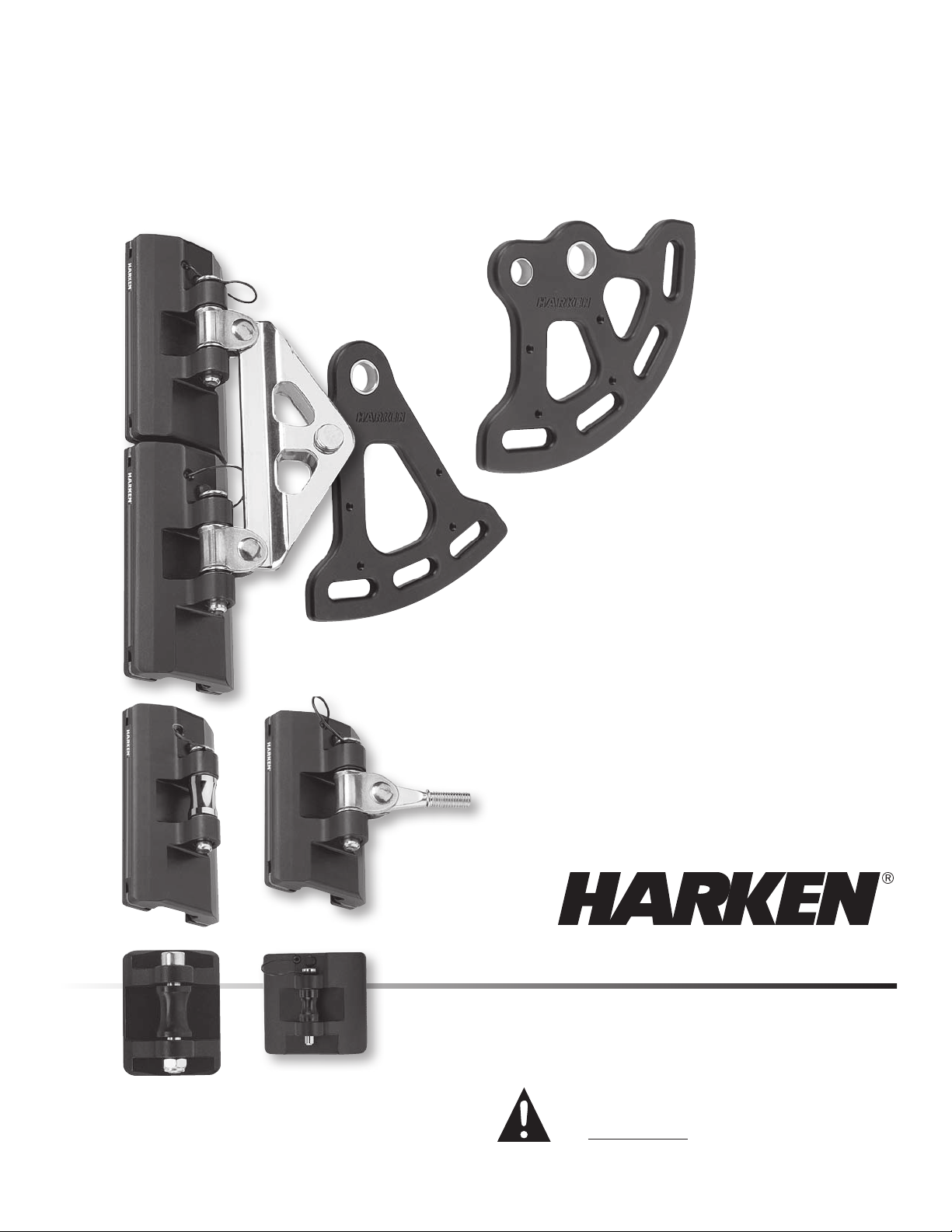
Battcar Installation Manual
System B CB – 10mm Clevis Pin
System B Slider Cars
WARNING!: Strictly follow all instructions to avoid an
accident, damage to your vessel, personal injury or death.
See www.harken.com for additional safety information.
Page 2
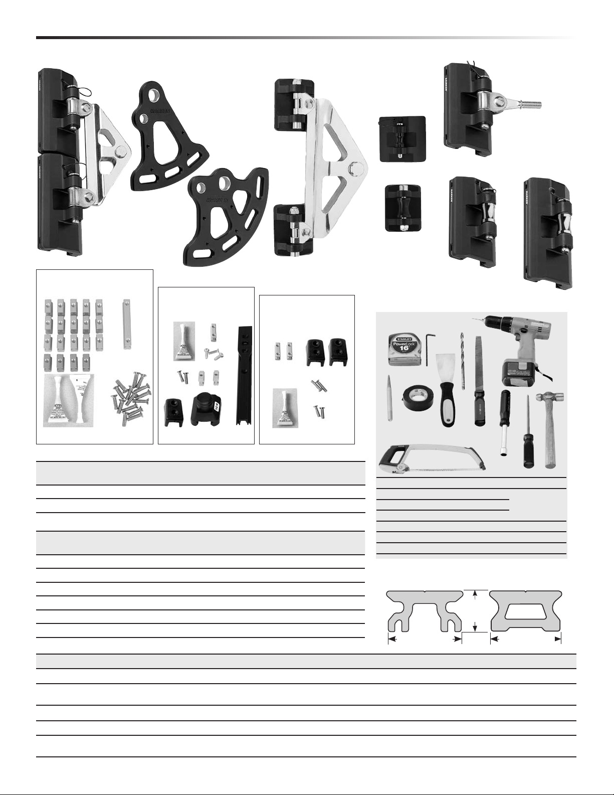
CB/Slider Systems Parts List
Thank you for puchasing Harken's B Battcar system. Please read manual before assembling system.
Headboard Cars (Assembly)
Headboard Cars (Assembly)
Batten Cars without Receptacles
3856/3857 – CB
3834/3835 – Slider
3861
CB–Web-On
Intermediate
Cars
Standard
3863 CB
Universal Battcar
Reef Car
3862
CB Web-On
Square Top
3852
CB
Track Mounting Kit
3845, 3846
Screwpin Endstop Kits
3847,3848
3833
Slider
Endstop Kits
3850, 3851
3836 Slider
3859 – CB
3860 – CB
Tools You Will Need:
f
c
b
a
g
f
i
j
2
1
4
3
h
h
c
CB System Parts
CB System
Part No.
3861
3862
CB/Slider Parts
CB System
Part No.
3852 3833
3863 3836
3856 3834
3857 3835
3859 —
3860 —
Standard web-on headboard See sailmaker instructions, page 12 - 14
Square top web-on headboard See sailmaker instructions, page 12 - 14
Slider System
Part No.
c
d
Description
Headboard cars 3852 must use 3861 or 3862 headboard.
Intermediate cars If battens are close enough intermediate cars are not needed.
Batten car 10mm Threaded stud. Purchase batten receptacle separately.
Batten car 12mm Threaded stud. Purchase batten receptacle separately.
Universal Battcar Purchase batten receptacle and threaded stud separately.
Reef Tack car Double up track screws at reefed car position.
j
Description
k
l
Comments
Comments
1. Tape measure 6. Hammer 11. File
2. Allen wrench 5mm 7. Hacksaw
3. Power drill (screwdriver) 8. Center punch
4. Drill bit -
5. Phillips screwdriver 10. Putty knife
Mast-up installation: stepladder secured to boat
Work height : 7' (2.13m) above boom
(Mounting Slug Type)
9
8
9
17
/64" (6.5mm) 9. Tape
Track
3844
11/16" (27mm)
10
11
12
7
Slider Cars
Only
(Drill and Tap Type)
9
/16"
(14mm)
11/16" (27mm)
Track and Accessories
Part No. Description Includes
3845, 3846
3847
3848
3850, 3851
3844
1616
2 System B (CB/Slider) 11-14-08
Track Mounting Kit (a) 19 mounting slugs
Screwpin
Endstop Kit
Endstop Kit (c) 1 tube blue Loctite®; (f) 2 stop slugs 1
Track (slug type) Section length: 6'9
Track (drill and
tap t ype)
(c) 1 tube blue Loctite®; (f) 1 top stop slug 1
30mm; (i) 2 mounting slugs
Use for mast s without grooves or when slugs will not fit. Purchase stainless steel
Do not use 3844 track. It requires mounting slugs. See page 8 for drill /tap sizes and mounting instructions.
7
/8" (22mm); (b) 1 connector slug 3" (76mm); (c) 2 Tubes Blue Loctite
7
7
/8" (22mm); (j) 1 top ends top 1522 A; (k) pin stop ; (l) 1 end track
1
/8" (2.06m). Number of track sections depends on luff length of your mainsail.
/16" (36mm); (g) 3 HFS321 flathead screws 6 x 20mm; (h) 2 HFS1037 flathead screws 6 x
7
/16" (36mm); (h) 4 HFS1037 flathead screws 6 x 30mm; (j) 2 endstops 1522A
®;
(d) 21 HFS321 Flathead screws 6 x 20mm.
1
/4" (6mm) screws separately.
6
5
12. Nut driver 10mm
or open/box-end
wrench
Track
1616
Page 3
CB/Slider Systems Sizing/Sail Modifications
3852
Sizing
Make sure that you have the correct size battcar system for your boat.
Maximum Sail Area
Monohull Multihull
CB System
2
900 ft
83 m
2
700 ft
65 m
Slider System
2
900 ft
83 m
2
700 ft
65 m
Headboard Cars
2
2
2
2
Part No.
3852 3856, 3857 3863
3833 3834, 3835 3836
Part No.
Battcars
Part No.
Intermediate Cars
Sail Modifications (See page 12)
CB Headboard
Web on headboard.
Slider Headboard
Drill holes in headboard for new halyard
location and coupler attachment. See
page 13.
Batten receptacle on sail to accept 10 mm ot
12 mm threaded stud. Note: Harken does
not supply receptacle.
Becket spacer on sail for 3863 (CB)
or 3836 (slider) intermediate cars.
CB/Slider Systems Track Length
1
10"
254 mm
Number of Track Sections
Botton endstop track and variable
length top track included.
Track Length
41'6" to 48'2"
12.649m to 14.681m
48'3" to 54'11"
14.707m to 16.739m
Number of
1
6'9
/8" (2.06m)
Track Sections
7
8
55'0" to 61'8"
16.764m to 18.796m
61'9" to 68'5"
18.821m to 20.853m
68'6" to 75'2"
20.879m to 22.911m
1
2
CB System
10"
254mm
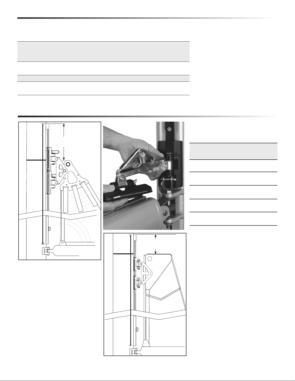
Determine Track Length
Measure track length from point 1 to
point 2. See diagram at left. Use this
measurement in two charts to follow.
9
10
11
1. Upper End—10" (254 mm) above black
band. Track is longer than sail luff length to
allow for stretch as sail ages. Track must
not block halyard exit.
2. Lower End, Using 3847, 3848—Bottom
of track will be approximately 3/8" (10 mm)
above gooseneck fitting. When installed,
track should be as low as possible yet you
should still be able to install long headboard
cars. Test measurement by using long
headboard car. See photo above.
3850, 3851 Endstop Kit—Cut a 93/8"
(238 mm) piece from finished end of one
of the 6'91/8" (2.06 m) 3844 tracks. You will
2
Slider System
remove this track when loading cars so it
can be lower on mast. See page 7, step 11.
Drill lower hole for stop. See page 5, step 3.
3-07 System B (CB/Slider) 3
Page 4

CB/Slider Systems Top Track Length
Round track length to nearest 1" (25 mm).
NOTE: Chart is based on using a 9
3
/8" (238 mm) or 91/2" (241 mm) lower end track.
Total Track Length (as defined on page 3) Top Track Length
41' 6" 12.649 m 48' 3" 14.707 m 55' 0 " 16.764 m 61' 9 " 18.821 m 68' 6" 20.879 m 11/2" 38 mm
3
41' 7" 12.675 m 48' 4" 14.732 m 55' 1" 16.789 m 61' 10" 18.847 m 68' 7" 20.904 m 2
41' 8" 12.700 m 48' 5" 14.757 m 55' 2" 16.815 m 61' 11" 18.872 m 68' 8" 20.930 m 3" 76 mm
41' 10 " 12.751 m 48' 7" 14.808 m 55' 4" 16.866 m 62' 1" 18.923 m 68' 10" 20.980 m 5" 127 mm
42' 0" 12.80 2 m 48' 9" 14.859 m 55' 6" 16.916 m 62' 3" 18.974 m 69' 0" 21.031 m 7" 178 mm
42' 2" 12.852 m 48' 11" 14.910 m 55' 8" 16.967 m 62' 5" 19.025 m 69' 2" 21.082 m 9" 229 mm
42' 4" 12.903 m 49' 1" 14.961 m 55' 10 " 17. 01 8 m 62' 7" 19.075 m 69' 4" 21.13 3 m 11" 279 mm
42' 6" 12.954 m 49' 3" 15.0 11 m 56' 0" 1 7.0 6 9 m 62' 9" 19 .126 m 69' 6" 21.18 4 m 1' 1" 330 mm
42' 8" 13.005 m 49' 5" 15.062 m 56' 2" 17.120 m 62' 11" 19 .177 m 69' 8" 21.23 4 m 1' 3" 381 mm
42' 10" 13.056 m 49' 7" 15.113 m 56' 4" 17.170 m 63' 1" 19.228 m 69' 10" 21.28 5 m 1' 5" 432 mm
43' 0" 13 .106 m 49' 9" 15.164 m 56' 6" 17. 22 1 m 63' 3" 19.279 m 70' 0" 21.3 36 m 1' 7 " 483 mm
43' 2" 13.157 m 49' 11" 15.215 m 56' 8" 17. 27 2 m 63' 5" 19.329 m 70' 2" 21.3 87 m 1' 9 " 533 mm
43' 4" 13.208 m 50' 1" 15.265 m 56' 10" 17. 3 23 m 63' 7" 19.38 0 m 70' 4" 21.438 m 1' 11" 584 mm
43' 6" 13.259 m 50' 3" 15.316 m 57' 0" 1 7.3 74 m 63' 9" 19.431 m 70' 6" 21.488 m 2' 1" 635 mm
43' 8" 13.310 m 50' 5" 15.367 m 57' 2" 17. 4 24 m 63' 11" 19.482 m 70' 8" 21.539 m 2' 3" 686 mm
43' 10" 13.360 m 50' 7" 15.418 m 57' 4" 17.47 5 m 64' 1" 19.533 m 70' 10" 21.59 0 m 2' 5" 737 mm
44' 0" 13.411 m 50' 9" 15.469 m 57' 6" 1 7.5 2 6 m 64' 3" 19.583 m 71' 0 " 21.641 m 2' 7" 787 mm
44' 2" 13.462 m 50 ' 11" 15.519 m 57' 8" 17. 57 7 m 64' 5" 19.634 m 71' 2" 21.692 m 2' 9" 838 mm
44' 4" 13.513 m 51' 1" 15.570 m 57' 10" 17.6 28 m 64' 7" 19.685 m 71' 4" 21.742 m 2' 11" 889 mm
44' 6" 13.564 m 51' 3" 15.621 m 58' 0" 1 7.6 78 m 64' 9" 19.73 6 m 71' 6" 21.793 m 3' 1" 940 mm
44' 8" 13.614 m 51' 5" 15.672 m 58' 2" 17. 7 29 m 64' 11" 19.787 m 71' 8 " 21.8 44 m 3' 3" 991 mm
44' 10" 13.665 m 51' 7" 15.723 m 58' 4" 17.7 8 0 m 65' 1" 19.837 m 71' 10" 21.895 m 3' 5" 1.041 m
45' 0" 13.716 m 51' 9" 15.7 73 m 58' 6" 1 7.8 3 1 m 65' 3" 19.888 m 72' 0" 21.946 m 3' 7" 1.092 m
45' 2" 13.767 m 51' 11" 15.824 m 58' 8" 17.8 82 m 65' 5" 19.939 m 72' 2" 21.996 m 3' 9" 1.14 3 m
45' 4" 13.818 m 52' 1" 15.875 m 58' 10 " 17. 93 2 m 65' 7" 19.990 m 72' 4" 22.047 m 3' 11" 1.19 4 m
45' 6" 13.868 m 52' 3" 15.926 m 59' 0" 1 7.9 8 3 m 65' 9" 20.041 m 72' 6" 22.098 m 4' 1" 1.245 m
45' 8" 13.919 m 52' 5" 15.977 m 59' 2" 18.034 m 65' 11" 20.091 m 72' 8" 2 2.14 9 m 4' 3" 1.295 m
45' 10" 13.970 m 52' 7" 16.027 m 59' 4" 18.085 m 66' 1" 20.1 42 m 72' 10" 22.200 m 4' 5" 1.346 m
46' 0" 14.021 m 52' 9" 16.078 m 59' 6" 18 .136 m 66' 3" 2 0.19 3 m 73' 0" 22.250 m 4' 7" 1.397 m
46' 2" 14.072 m 52' 11" 16.129 m 59' 8" 18.186 m 66' 5" 20.244 m 73' 2" 22.301 m 4' 9" 1.448 m
46' 4" 14.12 2 m 53' 1" 16 .180 m 59' 10" 18.237 m 66' 7" 20.295 m 73' 4" 22.352 m 4' 11" 1.499 m
46' 6" 14.17 3 m 53' 3" 16.231 m 60' 0" 18.28 8 m 66' 9" 20.345 m 73' 6" 22.403 m 5' 1" 1.549 m
46' 8" 14.224 m 53' 5" 16.281 m 60' 2" 18.339 m
46' 10" 14.275 m 53' 7" 16.332 m 60' 4" 18.390 m 67' 1" 20.447 m 73' 10" 22.504 m 5' 5" 1.651 m
47' 0" 14.326 m 53' 9" 16.383 m 60' 6" 18.4 40 m 67' 3" 20.498 m 74' 0" 22.555 m 5' 7" 1.702 m
47' 2" 14.376 m 53' 11" 16.434 m 60' 8" 18.491 m 67' 5" 20.549 m 74' 2" 22.606 m 5' 9" 1.753 m
47' 4" 14.427 m 54' 1" 16.485 m 60' 10" 18.5 42 m 67' 7" 20.599 m 74' 4" 22.657 m 5' 11" 1.80 3 m
47' 6" 14.478 m 54' 3" 16.535 m 61' 0 " 18.593 m 67' 9" 20.650 m 74' 6 " 22.708 m 6' 1" 1.85 4 m
47' 8" 14.529 m 54' 5" 16.586 m 61' 2" 18.64 4 m 6 7' 11" 20.701 m 74' 8" 22.758 m 6' 3" 1.905 m
47' 10" 14.580 m 54' 7" 16.637 m 61' 4" 18.69 4 m 6 8' 1" 20.752 m 74' 10" 22.809 m 6' 5" 1.9 56 m
48' 0" 14.6 30 m 54' 9" 16.68 8 m 61' 6" 18.74 5 m 68' 3" 20.803 m 75' 0" 22.860 m 6' 7" 2.007 m
48' 2" 14.6 81 m 5 4' 11" 16.739 m 6 1' 8" 18.796 m 68' 5" 20.853 m 75' 2" 22.911 m 6' 91/8" 2.060 m
66' 11" 20.396 m 73' 8" 22.454 m 5' 3" 1.600 m
/8" 60 mm
4 System B (CB/Slider) 6-06
Page 5
5 or
more
Slug
Slug
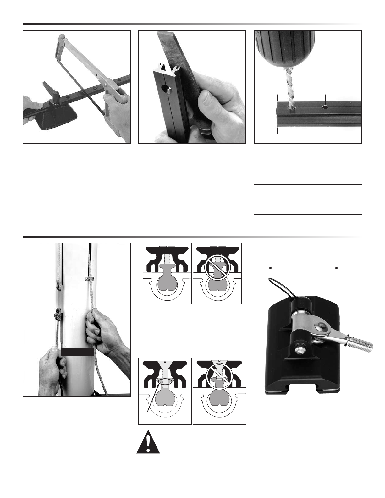
CB/Slider Systems Cut Top Track to Length
13/16"
(30 mm)
5
/
16
" (8 mm)
1. Cut special length top track from 6'91/8"
(2.06m) track.
2. Deburr cut.
Slightly round track corners that will slide
against mast.
3. Drill two 17/64" (6.5mm) holes in cut
end of track. Center at 5/16" (8mm) and
13/16" (30mm)
Short top track lengths
1
1
/2" (38mm) Use existing hole. Do not
drill second hole.
3
2
/8" (60mm) Use existing hole, drill hole
5
/16" (8mm) from cut end.
CB/Slider Systems Check Fit of Mounting Slugs & Car
Will Tighten
Will Not Tighten
Test track: Put mounting slug in groove,
track section on mast. Tighten with screw.
CB Cars 23/4" (70mm)
Slider Cars 1
11
/16" (42mm)
Mounting screw must be long enough for
mast groove. If necessary, purchase
Check Fit
3" (76mm) connector slug must fit feeder
opening. File opening to make longer.
Use halyard with retrieval line to run
3" (76mm) connector slug up mast
to check for burrs in groove.
Mast prebend: May require straightening
before installation.
09/01/09 System B (CB/Slider) 5
longer screws.
Warning!: Avoid personal injury
or death. Screws need minimun
5 threads (turns) engaged to
hold track to mast.
Turn screw 360° five times after
threads engage slug.
Cars must clear storm trysail track. Tracks
often converge above spreaders.
Aft face of mast must be flat or convex.
Page 6

CB/Slider Systems Install Track
1. Slip top track slugs into mast groove.
Use 17/16" (36mm) mounting slug for top
stop.
Short top track lengths Top slug
1
1
/2" (38 mm) 3" (76 mm)
3
2
/8" (60 mm)
7
/8" (22 mm)
Install 3" (76 mm) connector slug at
bottom.
Mast up: Tape 17/16" (36 mm) slug even
with top of upper track. Tape other slugs
in place.
2. One drop blue Loctite® into each
connector slug hole.
3. Thread a 6 x 30 mm screw through
endstop, track, and into endstop slug.
Short top track lengths
1
1
/2" (38mm) Use one screw in stop
3
2
/8" (60mm) Use both screws
5. Loosen top screw. Slide top track up and
position next 6'91/8" (2.06m) track.
4. Slide slugs into place with putty knife.
Loosely install 6 x 20mm screws.
Mast up: Remove tape.
TIP: Use putty knife to see if screws
are loose enough to slide in groove.
REMEMBER: Tracks may stick when
Mast up: Tighten bottom screw to hold
track.
6. Slide 19 mounting slugs and connector
slug into mast groove.
Mast up: Tape in place.
Put one drop blue Loctite® into each hole.
reaching a spliced area on mast.
6 System B (CB/Slider) 6-06
Page 7

CB/Slider Systems Install Track
7. Hold full-length track piece up to mast.
Loosely install top screw.
Use putty knife to slide additional slugs
and connector slug into place. Loosely
install all nineteen 6 x 20mm screws.
8. Slide tracks up enough to fit next track.
Mast up: Hold upper tracks. Loosen screw
that holds tracks. Slide track up. If screws
bind in mast groove opening, loosen them
untill track slides. Tighten new bottom
screw securely.
CAUTION! Do not let tracks
drop. Severe injury to hands
and/or fingers can result.
9. Repeat until full-length tracks installed.
NOTE: If bottom full-length track blocks
feeder gap, load bottom track slugs before
installing track.
10. Raise tracks so 91/2" (241mm) bottom
feeder track fits.
3850, 3851 Endstop Kit—leave
bottom 93/8" (238mm) track off
untill cars are installed.
11. Install bottom feeder track with stop.
07-01/09 System B (CB/Slider) 7
Page 8

CB/Sliders Systems Install Track by Drilling and Tapping
Required Parts
1616 Track
Determine Track Length.
Bottom track must be short enough to
remove easily. Use 18" to 24" (457mm
to 609 mm) length. Do not use 3844
track for drilling and tapping.
1
/4" (6mm) Flathead Screws (not
included)
10 fasteners/meter of track
1619 Splices
1522 Endstop Set
Drill and Tap sizes
U.S. Imperial Metric
Drill
Tap
13
/64" 5mm
1
/4–20 m6 x 1
Removing Old Track
Track on mast: Before removing, scribe
pencil line down either side of track.
Track off mast: Attach string to mast to
line up track during installation.
1616
1619
1522
1. Drilling, tapping, screwing: Start at one
end of track and work down: Do not drill
and tap from both track ends
Clamp or duct tape track on mast. Center
punch hole in center of track hole.
TIP: Use narrow shaft spring-loaded
machinist's center punch with plastic
centering tube or transfer punch.
8 System B (CB/Slider) 6-06
2. Drill track hole, holding drill
perpendicular to mast face. Tap threads
and install screws using blue Loctite®.
TIP: Use low speed drill with tap for
cutting threads.
IMPORTANT: Use blue Loctite® instead
of oil for tapping lubricant.
3. Align track at joints: Use 1619 splice
pieces and round rods or dowels to align
track during installation. Hold in place
with spring or “C" clamps until track
is secured.
Load all cars before installing bottom
track and endstop.
Page 9

CB System Load Cars on Track
IMPORTANT: To keep balls captive we recommend loading cars onto track without sail installed. Chart below shows correct number of
balls for each car.
1. Headboard car: Hold car so
clevis pin head faces up. Align
car on guide section of loader
track and gently roll onto upper
tracks. If cars stick, realign
and roll onto track.
2. Load intermediate car (if
used). Alternate with batten
cars until all cars are loaded.
Mast up: Use halyard to
hold cars.
3. Install pinstop. 3850, 3851 Endstop Kit—
Remove bottom 9
1
/2" (241mm)
track and install cars.
TIP: Use halyard to hold
cars up
TIP: To load headboard car assembly, angle headboard coupler. Roll car onto tracks. If necessary, remove headboard assembly.
CB System Lost Balls
Consult ball chart below to find number of balls for each car. To load balls, place car on edge with retaining clip in place.
Insert balls one-by-one from center of clip and roll into return race. Do not overfill car.
Part Length Bearing Quantity Ball ø
Number Car Type in mm Color Material per Car Part No. Balls/Set in mm
3852 Headboard Cars (2) 5
3863 Intermediate Car 29/16 68 Brown Torlon® 28 1526 25 5/16 8
3856 Battcar w/10mm Threaded Stud 41/4 108 Brown Torlon® 40 1526 25 5/16 8
3857 Battcar w/12mm Threaded Stud 41/4 108 Brown Torlon® 40 1526 25 5/16 8
3859 Universal Car 41/4 108 Brown Torlon® 40 1526 25 5/16 8
3860 Reef Car 53/16 132 Brown Torlon® 60 1526 25 5/16 8
3
/16 132 Brown Torlon® 60 1526 25 5/16 8
Slider System Load Cars on Track
Slider cars can be loaded onto tracks with
or without sail attached.
Line up car on guide portion of loader.
Press car towards mast and slide car onto
track. Begin with upper cars and work
down.
TIP: To load headboard car assembly,
angle headboard. Roll car onto tracks. If
necessary, remove headboard assembly.
3-07 System B (CB/Slider) 9
Page 10

Slider System Load Sail on Cars
1. Beginning with lower cars, use 5mm
allen wrench and 10mm wrench or nut
driver to attach sail to cars. Tighten
locknut until bottom tip of fastener
is flush with nut.
2. Screw threaded stud to terminal.
4. Attach head of sail to headboard
car with clevis pin and cotter pin.
3. Load toggle using 5mm allen wrench
and 10 mm wrench or nut driver. Tighten
locknut. Do not over tighten. Make sure
toggle can pivot.
CB System Load Sail on Cars
Attach sail to system
beginning with lowest
car. Line up toggle and
insert clevis pin.
If it is a “no wind” day,
start at headboard and
hoist mainsail as you
attach sail to cars.
10 System B (CB/Slider) 3-07
Page 11

H
A
R
K
E
N
H
A
R
K
E
N
Slider System Removing SailCB System Removing Sail
Press quick release
button and push
up on bottom of pin.
Remove clevis pin.
If your system
has slider battcars
without ball bearings, leave slides
attached and slide
cars off, beginning
at the bottom.
CB System Battcar Operating Precautions CB System Car Maintenance
When lowering sail, do not let halyard go. Ease cars down by
keeping a wrap on winch.
On boats with unstayed masts, vang must be used to prevent
over rotation of upper part of sail. Over rotation can damage
batten receptacles.
Clean beginning of season, or if cars
bind. Squirt detergent and water into
ball bearings. Circulate by moving
cars up and down. Let stand. To
remove detergent, spray water into
ball bearings and circulate. Clean
tracks with detergent and water.
For thorough cleaning, remove sail
then remove cars from track. Clean
as above. Once dry, apply a single
drop of McLube™ ball conditioner.
Circulate balls using a small
screwdriver.
Inspect Battcar fittings for loose
locknuts. Replace. Inspect batten
receptacles for loose screws.
CB/Slider Systems Lazy Jacks
Lazy Jacks
Use shock cord to hold lazy jacks open
so battcars and battens will not catch on
them. This will also help stop slapping of
lazy jacks on sail.
Attach one end to lower spreader tips and
the other to lazy jacks.
Make sure shock cord is long enough so
boom can swing out all the way without
damaging spreaders.
07/07/09 System B (CB/Slider) 11
Page 12

CB/Sliders Systems Sailmakers Instructions
CB
3859/3860,
3863
A
B
D
Slider
3836
E
A
A
Headboard Not
Included
A
E
CB
3852
Slider
3833
E
B
C
D
B
C
B
C
D
Dimensions (measured from aft face of mast)
E F
Part A B C D Pin Ø Stud Ø
No. Description in mm in mm in mm in mm in mm mm
System B CB
3852 Headboard car assembly 101/2 267 19/16 39 31/16 78 41/16 102
3863 Intermediate car 2
3856 Battcar/10mm stud 4
3857 Battcar/12mm stud 4
3859 Universal Battcar 4
3860 Reef car 5
9
/16 68 19/16 39 — —
1
/4 109 19/16 39 31/16 78 43/8 111
1
/4 108 19/16 39 31/16 78 43/8 111
1
/4 108 19/16 39 — — 1 26
3
/16 132 19/16 39 — — 1 26
3
/4 19
System B Slider
3833 Headboard car assembly 71/2 190 11/4 32 21/4 57 43/16 107
3834 Battcar/10mm stud 2
3835 Battcar/12mm stud 2
3836 Intermediate car 2
3
/16 56 11/4 32 21/4 57 39/16 91
3
/16 56 11/4 32 21/4 57 33/4 96
3
/16 56 11/4 32 — — — —
3
/8 10 —
1
/4 6 —
3
/8 10 10
3
/8 10 12
3
/8 10 —
3
/8 10 —
1
/4 6 —
1
/4 6 10
1
/4 6 12
1
/4 6 —
CB
3856/3857
Slider
3834/3835
F
E
D
12 System B (CB/Slider) 7-06
Page 13

CB/Sliders Systems Sailmakers Instructions
CB System Installing Headboard Car Assembly
Use 1" (25mm) webbing. Holes
in headboard accept 416 16mm
cheek blocks for leech line. Use
4mm x 10mm fasteners.
47/8"
78mm
31/16"
78mm
3861
CB–Web-On
Standard
511/16"
145mm
31/16"
78mm
3862
CB–Web-On
Square Top
Slider System Installing Headboard Car Assembly
Headboard coupler attaches
to standard headboards
—some headboard
modification required.
Maximum thickness of
headboard plates and
sail: 9/16" (14mm)
7
/8"
1
(48mm)
Coupler Attachment Hole
Drill 5/8" (16mm) coupler attachment hole so center
is 41/4" (108mm) from top of headboard and centered
17/8" (48mm) from front edge of boltrope:
Leave at least 3/4" (19mm) between front of headboard
plate and front edge of coupler attachment hole.
Halyard Attachment Hole
Use aft hole if headboard has two.
If not, drill second hole to accept
halyard shackle pin. Locate hole
approximately 21/2" (63.5mm)
aft of existing hole.
3-07 System B (CB/Slider) 13
Page 14

CB/Slider Systems Sailmaker's Instructions
Distance Between
Attachment Points
Battens and intermediate cars placed
at sailmaker's discretion. Maximum
distance between attachment points
is 4'to 4'6" (1.2m to 1.35m).
Distance may be slightly greater.
Contact Harken to discuss sail
reshaping to eliminate luff flutter.
NOTE: Adding battens may reduce
stack height by eliminating
intermediate cars.
Setting Reef Points
Space reef points halfway between
sail attachment points. Battens or
reef points may need to be moved.
Diagram A
NOTE: Batten fittings and cars
cannot handle reefing outhaul or
downhaul loads. Transfer loads
to a tack fitting. Diagram B
DIAGRAM A
CORRECT
DIAGRAM B
INCORRECT
CB/Slider Systems Attaching Sail to Intermediate Cars
Sail setback from luff tape to intermediate car clevis pin:
All CB Cars 3863 11/2" (38mm)
All Slider Cars 3836 1" (25mm)
Plastic spacers come with 3839 and 3836 intermediate cars.
Seize spacer to webbing by stitching just behind plastic spacer.
Seize webbing to sail by stitching up against sail.
Combining Intermediate Slider Cars with CB Battcars
Sail setback from luff tape to intermediate car clevis pin:
Slider with CB Cars 3836 13/4" (45mm)
If you combine 3836 Slider Intermediate cars with 3856, 3857
CB cars use the 13/4" (45mm) CB setback shown above.
Setback
3863, 3836
14 System B (CB/Slider) 11-14-08
Page 15

CB/Slider Systems Installation Troubleshooting
Problem Probable Cause Solution
Cut end of top or bottom track is at joint.
Tracks do not butt up against each other.
Track weight pulling tracks apart.
Mounting slugs do not fit. Slugs wrong size. Different size slug required. Contact your dealer.
Mounting screws will not tighten. Incorrect mounting slug used. Different size slug required. Contact your dealer.
Slugs catching on mast splice.
Corners of cut track catching. Use file to round off corners of track.
Track will not slide up mast.
Mast has too much prebend. Ease backstay and/or straighten mast.
Paint or other material clogging mast groove. Clean out groove.
CB/Slider cars do not fit on track.
CB cars do not fit on track.
Sail headboard does not fit inside coupler. Ring was not pressed far enough. Take sail to sailmaker.
Track and cars are not the same size. Contact your dealer or Harken.
Balls are missing. Remove cars, load balls and slide cars back on track.
Make sure the anodized end is towards the
full length track.
Tracks will come together when you loosen the
bottom screw and push the tracks up the mast.
Loosen screws slightly. If necessary have someone
at splice area to wiggle the slug past the splice.
Operation Troubleshooting
Problem Probable Cause Solution
Dirt in cars.
Cars bind.
Stud threaded too tightly into receptacle. Back off threaded stud two turns.
Balls missing from car. Remove cars, load balls and slide cars back on track.
Nut on Battcar is not holding. Locknut has been used too many times. Get new 6 mm locknut.
Batten receptacle does not rotate. Nuts are too tight. Loosen nuts slightly.
Cars jam when raising sail. Headboard or cars are catching on lazy jacks.
Sail will not go all the way up. Sail is too tall or sheave is too far forward. Have sail shortened or move sheave aft.
Vertical post or pin on batten receptacle bending. Reef loads are being transferred to batten receptacle.
Reef tack fitting will not reach reef hook. Reef point too close to sail attachment. Move intermediate car sail attachment.
Use detergent and fresh water to flush dirt out of
cars; move cars up/down do circulate; follow with
high pressure water; clean track grooves.
Use topping lift or rod vang and shock cord to pull
lazy jacks out to shrouds.
Transfer reef downhaul and outhaul loads to mast
or boom gooseneck.
Maintenance
®
equipment is designed for minimal maintenance, but some maintenance is required for optimum and safest possible operation and to comply with the Harken® limited
Harken
warranty. In general, the most important aspect of maintenance is to keep your equipment clean by frequently flushing with fresh water.
In corrosive atmospheres, stainless parts may show discoloration around holes, rivets and screws. This is not serious and may be removed with a fine abrasive.
With the exception of winches, do not use grease unless specifically recommended in the instruction sheet.
Flush blocks thoroughly with fresh water. Periodically, disassemble the blocks and clean with detergent and fresh water. Lubrication is not required, but lubricants which will
not attract dirt may be used like McLube®.
Important: Exposure to some teak cleaners and other caustic solutions can result in discoloration of part and is not covered under the Harken warranty.
Warranty
For additional safety, maintenance and warranty information see www.harken.com or the Harken® catalog.
4286/6-06 System B (CB/Slider) 15
Page 16

Corporate Headquarters
1251 East Wisconsin Avenue, Pewaukee, Wisconsin 53072 USA
Telephone: (262) 691-3320
Web: www.harken.com
• Fax: (262) 691-3008 • Cable: Harken Pewaukee
• Online Catalog: www.harkenstore.com
Email: harken@harken.com
Harken France
ZA. Port des Minimes, BP 3064, 17032 - La Rochelle Cedex 1, France
Telephone: (33) 05.46.44.51.20
• Fax: (33) 05.46.44.25.70
Web: www.harken.fr
Email: harken@harken.fr
Harken Italy S.P.A.
Via Marco Biagi, 14, 22070 Limido Comasco, (CO), Italy
Telephone: (39) 031.3523511
• Fax: (39) 031.3520031
Web: www.harken.it
Email: info@harken.it
Harken UK Ltd.
Bearing House, Ampress Lane
Lymington, Hampshire S041 8LW, England
Telephone: (44) 01590-689122
• Fax: (44) 01590-610274
Web: www.harken.co.uk
Email: enquiries@harken.co.uk
Harken Poland
ul. Lisa Kuli 4 Lok.1, 01-512 Warszawa, Polska
Telephone: +48 607 979 747
Web: www.harken.com
Email: polska@harken.com
Harken Sweden
Mjölkekilsgatan 8, Box 64
S-440 30 Marstrand, Sweden
Telephone: (46) 303-618 75
• Fax: (46) 303-618 76
Web: www.harken.se
Email: harken@harken.se
Harken Adriatik d.o.o.
Obala 107
6320 Portoroz, Slovenia
Telephone/Fax: 5-6774122
Web: www.harken.si
Email: info@harken.si
Harken Australia, Pty, Ltd.
1B Green Street
Brookvale, N.S.W. 2100, Australia
Telephone: (61) 2-8978-8666
• Fax: (61) 2-8978-8667
Web: www.harken.com.au
Email: info.harken.com.au
Harken New Zealand, Ltd.
30-36 Fanshawe Street
Auckland 1001, New Zealand
Telephone: (64) 9-303-3744
• Fax: (64) 9-307-7987
Web: www.harken.co.nz
Email: harken@harken.co.nz
Please visit: http://www.harken.com/dealers/dealers.php
for an up-to-date list of Harken dealers and distributors
Printed in USA 4286/7-09
 Loading...