

Page 1

INSTRUCTIONS
57 mm, 75 mm Carbo Ratchamatics
USA – Tel: (+1) 262-691-3320 • Web: www.harken.com • Email: harken@harken.com
Italy – Tel: (+39) 031.3523511 • Web: www.harken.it • Email: techservice@harken.it
Strictly follow all instructions to avoid an accident, damage to your vessel, personal injury
or death. See www.harken.com for additional safety information.
IMPORTANT: See Inspection and Maintenance
at end of manual.
Features
C
A
Do not apply a load greater than the Maximum working load (MWL) of the Carbo Ratchet listed below.
Part
No.
Description in mm in mm in mm in mm lb kg lb kg
57 mm
2625 Single 21/457 41/161033/1653/810 500 227 2000 907
2626 Single/becket 2
2627 Single/150 Cam-Matic
2628 Single/150 Cam-Matic
2633 Cheek** 2
2629 Triple/150 Cam-Matic
2630 Triple/150 Cam-Matic
Triple/150 Cam-Matic
2632
block/becket
2634 Double 2
75 mm
2680 Single 215/1675 53/81371/467/1612 750 341 3000 1361
2681 Single/becket 2
2682 Cheek** 2
2683 Single/150 Cam-Matic
2684 Single/150 Cam-Matic
2685 Triple/150 Cam-Matic
Triple/150 Cam-Matic®/becket‡ 215/1675 61/21655/1687/1612 1800 816 4500 2041
2686
Triple/150 Cam-Matic
2687
block/becket
**Includes RH fasteners and mounting pad.
®
®
/becket 21/457 415/161253/1653/810 600 272 1500 680
®
®
/becket 21/457 415/161251/463/810 1800 816 4500 2041
®
/40 mm
®
®
/becket 215/1675 61/21651/467/1612 600 272 1500 680
®
®
/57 mm
Load-sensing ratchet block: rolls freely in both directions
under low loads and automatically engages ratchet as loads
increase.
Eight-facet sheave: holds line securely.
Ratchet engagement adjustable: adjustable to ratchet at
higher/lower load according to sailor's strength and sailing
style.
B
Glass-filled nylon sideplates: load-carrying curved bearing
races.
Machined Hardkote-anodized aluminum sheaves: strength
and corrosion resistance.
Cam arm locking plates: Allows cam arms to be locked in
more than five positions for fair leads.
Cheek: Line-shedding, small mounting footprint and drain
holes. Mounts on port or starboard.
Common uses: Main/jib/spinnaker sheets/traveler controls/
genoa sheets/foreguys
A B C
1
/457 415/161253/1653/810 500 227 2000 907
21/457 41/161033/1653/810 300 136 750 340
1
/457 31/483 — —3/810 500 227 2000 907
21/457 41/161031/463/810 1500 680 3750 1700
1
/457 61/81561/463/810 1800 816 4500 2041
2
1
/457 49/161161/463/810 750 340 1875 851
15
/1675 61/21651/467/1612 750 341 3000 1361
15
/1675 41/16103 — —7/1612 750 341 3000 1361
215/1675 57/161381/467/1612 300 136 750 340
215/1675 63/161375/1687/1612 1500 680 3750 1700
15
/1675 61/21655/1687/1612 1800 816 4500 2041
2
Max line ØMaximum
working load
Breaking
load
Ratchamatic Blocks
Ratchet blocks are hand and crew savers. The eight-sided sheave grips loaded
sheets with up to 15: 1 holding power. Ratchamatic blocks spin freely in both
directions under low load. At higher load, ratchet engages, providing holding
power. As the load decreases, the ratchet shifts back into light air mode and
free spins. Unloaded main and jib sheets run out freely during mark roundings
and asymmetrical spinnakers run free during jibes.
57 mm (10:1 Holding Power), 75 mm (15:1 Holding Power)
Page 2
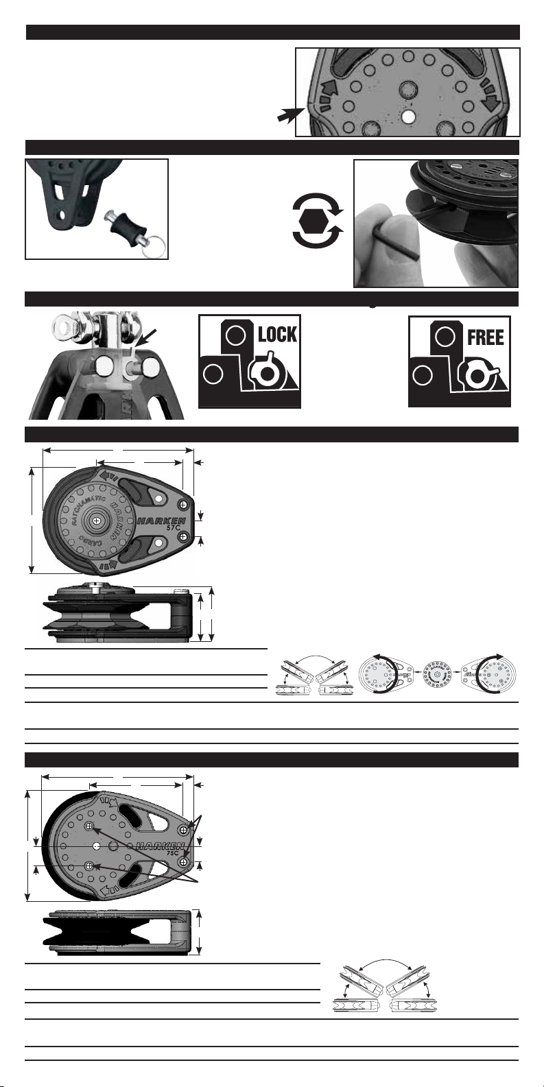
Ratchet Direction
Arrow on side of block shows direction that sheave
will spin in ratchet mode. Refer to arrow when
reeving block or mounting cheek block.
Adjusting Ratchet
INSERT
2.5 mm allen wrench
(included)
ALIGN HOLE in sheave
with bottom of block
Remove becket to access
ratchet adjustment hole.
3-Way Cam-Lock—All Ratchamatic Singles
1
2633 Cheek Block
D
B A
E
Remove circular mounting cap. Position block so ratchet turns
in desired direction (see drawing below). Flip block to change
direction. Use chart below or use block as a template and mark
holes using centerpunch. Check marks with block before
drilling. Remove block and drill holes using drill shown below
in chart. Bevel top of deck holes using a small knife to allow
C
sealant to mass. Place gasket under block. Through-bolt block
using recommended stainless steel fasteners, washers and
locknuts. Do not overtighten center screw or ratchet will bind.
Test block after mounting to make sure ratchet engages
smoothly and rotation direction is correct.
Ratchamatic cheek blocks include metric roundhead screws,
G
F
washers and nuts. See chart.
HEAVIER
LOADS
LIGHTER
LOADS
1. Cam lever up.
Block locks in
front or side
position.
2. Cam lever down.
Block turns
freely.
2
Block
Part No. Size
2633 57 mm 4.25
*Fastener length: Add deck thickness and overhang for nut and washer.
Block
Part
Size
No.
57 mm 2633
Drill Size
11
/
64
A B C D E F G
in mm in mm in mm in mm in mm in mm in mm
7
/
32
6 13/444.521/648.3 31/483 21/457 1 25 15/3229
Supplied
Fastener x Lengthmm in
M4 x 60 mm
2682 Cheek Block
F
B A
Deck Hole Drill
13
/
5.25 mm (
E
C
Block
Part No. Size
2682 75 mm 4.25 / 5.25
*Fastener length: Add deck thickness and overhang for nut and washer.
Block
Part
Size
75mm 2682
in mm in mm in mm in mm in mm in mm in mm
No.
9
/
32
Drill Sizes
A B C D E F G
7 217/326417/3213.527/6411 215/1675 41/16103 11/431
D
Deck Hole Drill
4.25 mm (
G
11
/
64
/ 13/
64")
11
/
64")
64
Fastener x Lengthmm in
M4 / M5 x 60 mm
Position block so ratchet turns in desired direction.
Refer to arrow for sheave direction in ratchet mode.
Flip block to change direction. Use chart below or use
block as a template. Mark holes using centerpunch.
Check marks with block before drilling. Remove block.
Important—holes are different diameter. Use two
drill sizes for deck holes. See chart and diagram. Bevel
top of deck holes using a small knife to allow sealant
to mass. Place gasket under block. Through-bolt block
using recommended stainless steel fasteners, washers
and locknuts.
Ratchamatic cheek blocks include metric roundhead
screws, washers and nuts. See chart below:
Supplied
Page 3

3-Way U-Lock—2629 / 2630 / 2632 / 2634 / 2685 / 2686 / 2687
5:1 Right-Angle Reeving
Dead-end on Becket
6:1 Right-Angle Reeving
Dead-end on becket
The 3-Way U-Lock on doubles and triples allows a change
of headpost direction from front to side or allows the
block to swivel. To change headpost direction, remove
shackle, turn post, install shackle. Remove U-Lock to
allow block to swivel.
Adjust Cam Angle (Single/Triple) Reverse Cam Cleat (Single Only)
1. Loosen cam arm locking plate screw and
pull outward to disengage.
2. Rotate cam arm to desired position.
3. Press locking plate in and tighten screw.
Avoid binding
sheave, do
not over tighten
screw.
1. Remove screws from cam.
2. Assemble as shown. Note: use
plastic plate on cam bottom.
3. Tighten screws. Do not
overtighten screws. Cam
pawls should snap shut smartly.
Part No.
HFS889
1
2
Reeving Multi-Purchase Systems
Right-angle reeving dead-end on becket
4
8
6
7
3
2
5
1
5:1
5
4
6:1
5
3
1
2
6
6
1
2
5
4
3
8:1
For larger, printable diagrams, please see: www.harken.com.
Inspect Block and Shackle Before You Sail
WARNING! Failure to inspect and replace damaged metal parts and/or worn or frayed line
can cause block or system to break suddenly causing an accident, damage to your vessel,
personal injury or death. See www.harken.com for additional safety information.
Frequently inspect shackles and shackle posts for signs of corrosion, cracks, or elongation. When
replacing shackles, use the correct Harken parts to maintain the proper strength. Replace line as
necessary, taking into consideration the maximum size recommendation.
Maintenance
Harken equipment is designed for minimal maintenance. However, some upkeep is required to give
the best service and comply with the Harken limited warranty.
Keep your equipment clean and free-running by frequently flushing with fresh water. Periodically
clean with mild detergent and water solution. Spin sheaves to distribute soap solution evenly.
Flush with fresh water.
Important: Exposure to some teak cleaners and other caustic solutions can result in discoloration
of part and is not covered under the Harken warranty.
Warranty
For additional safety, maintenance, and warranty information see www.harken.com or the Harken®
catalog.
M1004/1-17-11
 Loading...