

Page 1

Page 2
hanks for buying a Harken Battcar System. It will give you reliable
T
service with minimal maintenance, but does require proper assembly
and basic care. This manual is an important part of your mainsail
handling system. Please take the time to read it carefully before
assembling or using your Battcar system.
hese instructions may look intimidating, but they are very simple and
T
use photos and drawings throughout to make assembly easy. Many sections will not apply to your boat or to your installation.
f you have questions that cannot be answered by the manual or your
I
dealer, please feel free to give us a call. We'll be happy to do anything
we can to make your sailing safer and more fun.
Contents Page
Sizing and Parts List ................................ 3
Required Tools..................................... 4
Determining and Adjusting Track Length ................ 4
Cutting Top Track to Length ........................5 - 6
Checking Fit of Mounting Slugs and Cars ............... 6
Installing Track — Groove Mast .....................7 - 8
Installing Track — Drilling and Tapping................. 9
Loading Cars on Track..............................10
Attaching Sail to Cars .............................. 11
Lazy Jacks ....................................... 12
Operation and Maintenance.......................... 12
Removing Sail .................................... 12
Sailmaker’s Instructions ........................ 13 - 18
Troubleshooting — Installation & Operation ............ 19
2
Page 3
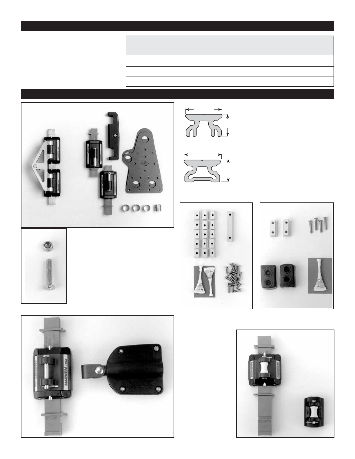
Sizing
Make sure that you have the correct size
Battcar system for your boat.
1 - Coupler
2 -
Headboard
Cars
1792
1807
Maximum Sail Area
Monohull Multihull
2
350 ft
33 m
425 ft
39 m
550 ft
51 m
2
2
2
2
2
300 ft
28 m
350 ft
32 m
475 ft
34 m
Parts List
2 -
Headboard Plates
(1792 Only)
4 - 19 mm Rings
2
2
2
2
2
2
System Headboard
A
Low Load
A
A
Hi-Load
7
/8" (22 mm)
7
/8" (22 mm)
15 - Mounting Slugs
3
/4" (19 mm)
1
/2"
(12 mm)
1
/2"
(12 mm)
1792HL
Part No.
Battcars
1807
1792
1807
1901, 1944,
1976, 1977
1825, 1901,
1944, 1976
1825HL, 1901HL, 1944HL,
1976HL, 1977HL
1800 TRACK, 6'83/4" (2.05 m) long:
Number of sections will vary according
to luff length.
Make sure you have the correct size track.
System A track is 7/8" (22 mm) wide.
2720 Track: for drilling and tapping
you must use 2720 track. Use 10-32
(5 mm) screws, not included.
Do not use 1800 open backed track
for drilling and tapping the mast. This
track must have the support of the
mounting slugs.
See page 9 for mounting instructions.
Luff
Car
1777
1894
1894HL
1 -
Screw and
Nut for
1944
Receptacle
HEADBOARD ASSEMBLY
1 - Connector Slug
5
/8" (67 mm)
2
17 - Flathead Screws
®
5 mm x 16 mm
2 - Tubes
Blue Loctite
MOUNTING KIT
One required for each track.
LUFF CARS
Luff cars not required
if battens are close
enough to support sail.
BATTCARS
Harken fitting is shown.
You may have Battslide,
Rutgerson or SDA batten
receptacles supplied
separately.
2 - End Stops
1
/4" (32 mm)
1
2 - Rubber End Stops
4 - Flat Head Screws
5 mm x 25 mm
1 - Tube
Blue Loctite
END KIT
One required for each system.
®
3
Page 4

Required Tools Determining Track Length
HARKE
N
USA
HARKE
N
USA
Phillips screwdriver Drill
Tape measure
Putty knife File
Hacksaw Tape
Hammer Socket wrench
Center punch Power driven screwdriver
Step Ladder: If you are installing the system with
the mast up, use a step ladder that can be secured
to the boat near the mast.
You will need to work at a hand height of
about 7' (2.13 m) above the gooseneck.
13
/64" (5.5 mm) drill bit
Note: Track length is greater than luff length of sail.
The track must extend at least 8" above the point where the halyard is attached to
the Harken headboard. Allow for sail stretch.
Make sure the top of the track does not interfere with the halyard exiting from the
mast.
3
The set back for the halyard from the aft side of the mast is 3
/4" (96 mm). See
Diagram A.
Remember to leave 1/4" (6 mm) beyond each end of the track for the end stops.
At the lower end, the track must extend as close to the gooseneck as possible
and ideally below the top of the boom.
Adjusting 1800 Track Length
The length of the track is matched to the mast by adjusting the number of 6'83/4"
(2.05 m) track lengths and by cutting the top and bottom track pieces to length.
Consult chart below to determine how many total track pieces you will need.
Consult the charts below to determine whether you need to cut your top track to
length.
All mast lengths will require cutting the bottom track. A short bottom track allows
cars to be easily loaded. See page 10.
How Many 1800 Track Sections?
Use the chart below to determine the total number of full length 6'83/4" (2.05 m) track
sections required for installation.
The variable length top and bottom tracks are included in this number.
Track Length of Mast
(As Described in Diagram A)
28'9" to 33'8"
(8.763 m to 10.262 m)
33'9" to 40'5"
(10.287 m to 12.319 m)
40'6" to 47'2"
(12.344 m to 14.376 m)
47'3" to 53'11"
(14.402 m to 16.434 m)
54' to 60'7"
(16.459 m to 18.466 m)
60'8" to 62'
(18.491 m to 18.898 m)
Number of 6'83/4 " (2.05 m)
Track Sections Required
5
6
7
8
9
10
DIAGRAM A: Determining Track Length
Full Length 6'83/4" (2.05m) Top Track
Round your track length to the nearest 1" (25 mm). If your track length is one of the dimensions shown below, your track system does not
need a special length top track. A full length 6'83/4" (2.05 m) track is used as the top track.
28'5" (8.661 m) 35'2" (10.719 m) 41'11" (12.776 m) 48'08" (14.834 m) 55'4" (16.866 m)
28'6" (8.687 m) 35'3" (10.744 m) 42' 0” (12.802 m) 48'09" (14.859 m) 55'5" (16.891 m)
28'7" (8.712 m) 35'4" (10.770 m) 42' 1" (12.827 m) 48'10" (14.884 m) 55'6" (16.916 m)
4
Page 5

Cutting Top Track To Length
Total Track Length (as defined on page 4) Top Track Length
28' 8" ( 8.738 m) 35' 5” (10.795 m) 42' 2" (12.852 m) 48'11" (14.910 m) 55' 7" (16.942 m) 3" ( 76 mm)
28'10" ( 8.788 m) 35' 7" (10.846 m) 42' 4" (12.903 m) 49' 1" (14.961 m) 55' 9" (16.993 m) 5" (127 mm)
29' 0“ ( 8.839 m) 35' 9" (10.897 m) 42' 6" (12.954 m) 49' 3" (15.011 m) 55'11" (17.043 m) 7" (178 mm)
29' 2" ( 8.890 m) 35'11" (10.947 m) 42' 8" (13.005 m) 49' 5" (15.062 m) 56' 1" (17.094 m) 9" (229 mm)
29' 4" ( 8.941 m) 36' 1" (10.998 m) 42'10" (13.056 m) 49' 7" (15.113 m) 56' 3" (17.145 m) 11" (279 mm)
29' 6" ( 8.992 m) 36' 3" (11.049 m) 43' 0” (13.106 m) 49' 9" (15.164 m) 56' 5" (17.196 m) 1' 1" (330 mm)
29' 8" ( 9.042 m) 36' 5" (11.100 m) 43' 2" (13.157 m) 49'11" (15.215 m) 56' 7" (17.247 m) 1' 3" (381 mm)
29'10" ( 9.093 m) 36' 7" (11.151 m) 43' 4" (13.208 m) 50' 1" (15.265 m) 56' 9" (17.297 m) 1' 5" (432 mm)
30' 0” ( 9.144 m) 36' 9" (11.201 m) 43' 6" (13.259 m) 50' 3" (15.316 m) 56'11" (17.348 m) 1' 7" (483 mm)
30' 2" ( 9.195 m) 36'11" (11.252 m) 43' 8" (13.310 m) 50' 5" (15.367 m) 57' 1" (17.399 m) 1' 9" (533 mm)
30' 4" ( 9.246 m) 37' 1" (11.303 m) 43'10" (13.360 m) 50' 7" (15.418 m) 57' 3" (17.450 m) 1'11" (584 mm)
30' 6" ( 9.296 m) 37' 3" (11.354 m) 44' 0” (13.411 m) 50' 9" (15.469 m) 57' 5" (17.501 m) 2' 1" (635 mm)
30' 8" ( 9.347 m) 37' 5" (11.405 m) 44' 2" (13.462 m) 50'11" (15.519 m) 57' 7" (17.551 m) 2' 3" (686 mm)
30'10" ( 9.398 m) 37' 7" (11.455 m) 44' 4" (13.513 m) 51' 1" (15.570 m) 57' 9" (17.602 m) 2' 5" (737 mm)
31' 0” ( 9.449 m) 37' 9" (11.506 m) 44' 6" (13.564 m) 51' 3" (15.621 m) 57'11" (17.653 m) 2' 7" (787 mm)
31' 2" ( 9.500 m) 37'11" (11.557 m) 44' 8" (13.614 m) 51' 5" (15.672 m) 58' 1" (17.704 m) 2' 9" (838 mm)
31' 4" ( 9.550 m) 38' 1" (11.608 m) 44'10" (13.665 m) 51' 7" (15.723 m) 58' 3" (17.755 m) 2'11" (889 mm)
31' 6" ( 9.601 m) 38' 3" (11.659 m) 45' 0” (13.716 m) 51' 9" (15.773 m) 58' 5" (17.805 m) 3' 1" (940 mm)
31' 8" ( 9.652 m) 38' 5" (11.709 m) 45' 2" (13.767 m) 51'11" (15.824 m) 58' 7" (17.856 m) 3' 3" (991 mm)
31'10" ( 9.703 m) 38' 7" (11.760 m) 45' 4" (13.818 m) 52' 1" (15.875 m) 58' 9" (17.907 m) 3' 5" (1.041 m)
32' 0” ( 9.754 m) 38' 9" (11.811 m) 45' 6" (13.868 m) 52' 3" (15.926 m) 58'11" (17.958 m) 3' 7" (1.092 m)
32' 2" ( 9.804 m) 38'11" (11.862 m) 45' 8" (13.919 m) 52' 5" (15.977 m) 59' 1" (18.009 m) 3' 9" (1.143 m)
32' 4" ( 9.855 m) 39' 1" (11.913 m) 45'10" (13.970 m) 52' 7" (16.027 m) 59' 3" (18.059 m) 3'11" (1.194 m)
32' 6" ( 9.906 m) 39' 3" (11.963 m) 46' 0' (14.021 m) 52' 9" (16.078 m) 59' 5" (18.110 m) 4' 1" (1.245 m)
32' 8" ( 9.957 m) 39' 5" (12.014 m) 46' 2" (14.072 m) 52'11" (16.129 m) 59' 7" (18.161 m) 4' 3" (1.295 m)
32'10" (10.008 m) 39' 7" (12.065 m) 46' 4" (14.122 m) 53' 1" (16.180 m) 59' 9" (18.212 m) 4' 5" (1.346 m)
33' 0” (10.058 m) 39' 9" (12.116 m) 46' 6" (14.173 m) 53' 3" (16.231 m) 59'11" (18.263 m) 4' 7" (1.397 m)
33' 2" (10.109 m) 39'11" (12.167 m) 46' 8" (14.224 m) 53' 5" (16.281 m) 60' 1" (18.313 m) 4' 9" (1.448 m)
33' 4" (10.160 m) 40' 1" (12.217 m) 46'10" (14.275 m) 53' 7" (16.332 m) 60' 3" (18.364 m) 4'11" (1.499 m)
33' 6" (10.211 m) 40' 3" (12.268 m) 47' 0” (14.326 m) 53' 9" (16.383 m) 60' 5" (18.415 m) 5' 1" (1.549 m)
33' 8" (10.262 m) 40' 5" (12.319 m) 47' 2" (14.376 m) 53'11" (16.434 m) 60' 7" (18.466 m) 5' 3" (1.600 m)
33'10" (10.312 m) 40' 7" (12.370 m) 47' 4" (14.427 m) 54' 1" (16.485 m) 60' 9" (18.517 m) 5' 5" (1.651 m)
34' 0” (10.363 m) 40' 9" (12.421 m) 47' 6" (14.478 m) 54' 3" (16.535 m) 60'11" (18.567 m) 5' 7" (1.702 m)
34' 2" (10.414 m) 40'11" (12.471 m) 47' 8" (14.529 m) 54' 5" (16.586 m) 61' 1" (18.618 m)
34' 4" (10.465 m) 41' 1" (12.522 m) 47'10" (14.580 m) 54' 7" (16.637 m) 61' 3" (18.669 m)
34' 6" (10.516 m) 41' 3" (12.573 m) 48' 0” (14.630 m) 54' 9" (16.688 m) 61' 5" (18.720 m)
34' 8" (10.566 m) 41' 5" (12.624 m) 48' 2" (14.681 m) 54'11" (16.739 m) 61' 7" (18.771 m)
34'10" (10.617 m) 41' 7" (12.675 m) 48' 4" (14.732 m) 55' 1" (16.789 m) 61' 9" (18.821 m)
35' 0" (10.668 m) 41' 9" (12.725 m) 48' 6" (14.782 m) 55' 3" (16.840 m) 61'11" (18.872 m)
5' 9" (1.753 m)
5'11" (1.803 m)
6' 1" (1.854 m)
6' 3" (1.905 m)
6' 5" (1.956 m)
6' 7" (2.006 m)
5
Page 6
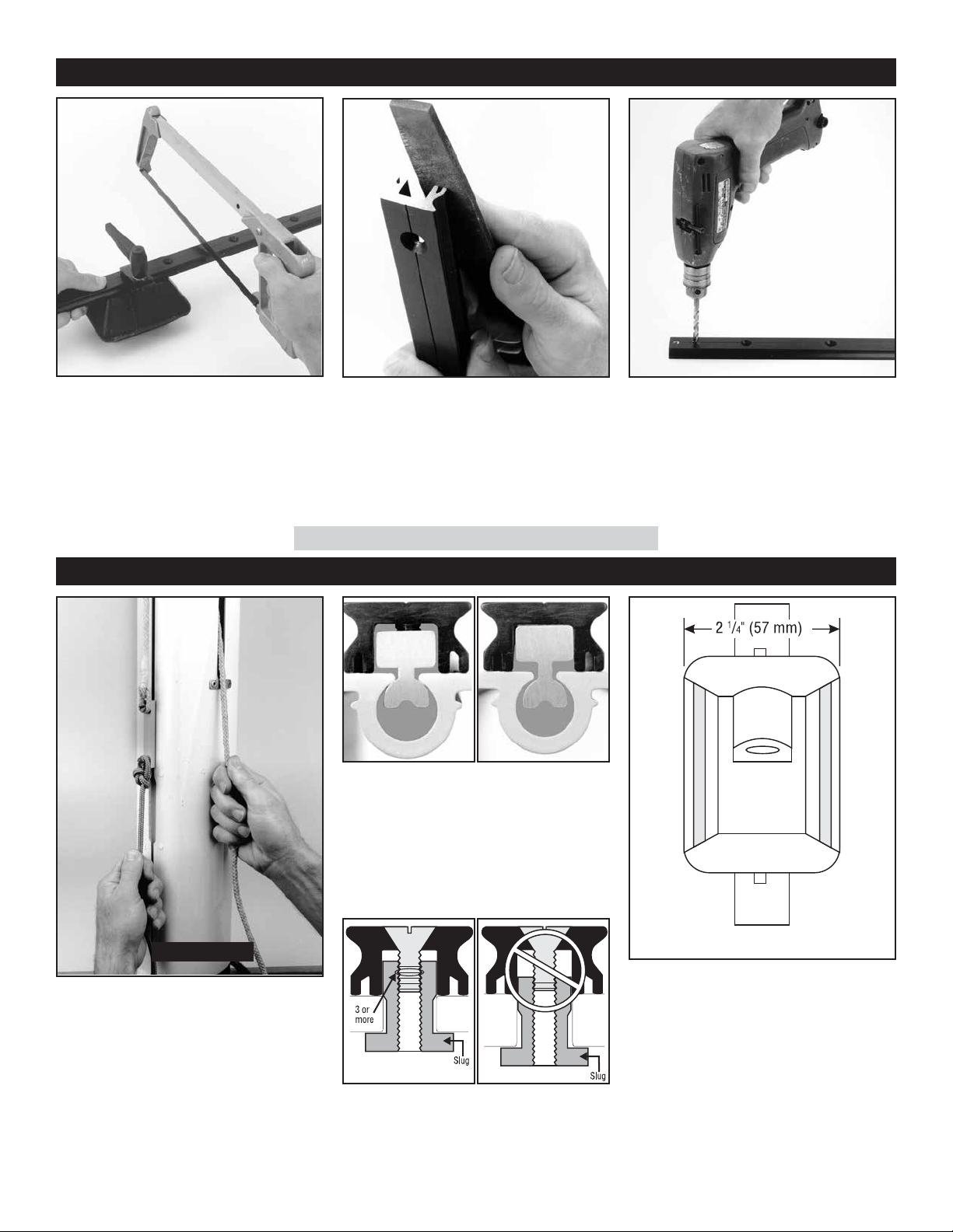
Cutting Top Track To Length
If your track length is shown in the chart
on page 5, use a hacksaw to cut a special
length of top track from a 6'83/4" (2.05 m)
track.
Round your track length to the nearest 1/2"
(10 mm) and extrapolate to determine the
top track length.
Before You Start...will mounting slugs and cars fit?
Use a file to deburr the cut.
Slightly round off the corners of the track
that will slide against the mast so it will not
catch when sliding the track up the mast.
NOTE: You will cut the bottom track in Step 10.
Will Tighten
To make sure the track will tighten against
mast, put a mounting slug in the groove, a
track section on the mast and use a screw
to test.
Also, make sure mounting screw is long
enough for your mast groove.
Will Not Tighten
Drill two 13/64" (5.5 mm) holes in the cut end
of the top track centered at 5/16" (8 mm) and
11/16" (27 mm) from the track end.
Slip the rubber end stop over the cut end
of the top track.
Check Fit
Check to make sure the 25/8" (67 mm) long
connector slug will fit in the feeder opening.
If necessary, use a file to make the feeder
opening longer.
Use a halyard to run the 25/8" (67 mm) long
connector slug up the entire mast. Use a
retrieval line. If it jams, clean the groove.
If there is prebend in the mast, you may
need to straighten it out somewhat to
install the battcar system.
6
Clear of Trysail Track?
Cars are 21/4" (57 mm) wide. Make sure they
do not hit trysail track or other obstruction
up the entire spar. Tracks often converge
above the spreaders.
Warning! Screws must have three (3)or
more threads engaged to hold track to mast.
Make sure screw makes three (3) full 360°
rotations after threads engage in slug.
Page 7

Installing Track
Slip the slugs for the
1
top track into the mast
groove starting with 11/4"
(32 mm) end stop slug.
Make sure the 25/8"
(67 mm) connector
slug is at the bottom.
If the mast is up, tape 11/4"
(32 mm) slug in place so
it will be even with the top
of the upper track.
Tape the other slugs
in place.
Put a drop of blue
2
Loctite into each
connector slug hole.
Use a putty knife to
4
slide the next slugs
into place and loosely
install the 5/8" (16 mm)
screws.
Tip: Use the putty knife
as a feeler gauge to
make sure the screws
are loose enough to
slide easily in the
groove.
REMEMBER: The tracks
may slide up the lower
part of the mast but
may hang up when they
reach a spliced area of
the mast.
Loosen the top screw
5
and slide the top track
up far enough to place
the next 6'83/4" (2.05 m)
track in place.
Mast up: tighten bottom
screw to hold the track
in place.
Thread a 1" (25 mm)
3
long end stop screw
through the rubber end
stop, track and into end
stop slug.
If the mast is up, remove
the tape and tighten the
screw enough to hold
the track in place.
Loosely install the other
1" (25 mm) screw.
Slide 15 mounting
6
slugs and a connector
slug into the mast groove.
Mast up: tape in place.
Put a drop of blue Loctite
in each hole.
7
Page 8

Installing Track
Hold a full-length track
piece up to the mast and
loosely install the top
screw.
Warning! Do not let
tracks drop, severe injury can result if the upper
track(s) drop down.
Use a putty knife to slide
the next slugs and connector slug in place and
loosely install the 5/8"
(16 mm) screws.
Push tracks up so the
9
173/4" (451 mm) to
193/4" (502 mm) bottom
track will fit below. See
step 10. The rubber end
stop extends 1/4" (6 mm)
below the bottom of the
track.
Do not install the bottom
track yet.
Refer to the chart
10
below to find your
bottom track length.
From the track that is
remaining, measure from
the anodized end and cut
the track.
Round your track length to the nearest 1" (25 mm). Make
bottom track 17
Make bottom track 183/4" (476 mm) if length is listed below
3
/4" (451 mm) if not listed below
Slide tracks up far
7
enough to fit the
next track.
Mast up: hold upper
tracks, loosen screw that
holds the tracks in place
and slide track up.
Loosen screw enough so
the track will slide up the
mast.
Securely tighten the
new bottom screw.
Repeat until all full
8
length tracks are
installed.
Do not install the 2
(67 mm) connector
slugs at this time.
Note: If the bottom full
length track blocks the
feeder gap, load slugs for
the bottom track before
installing the full length
track.
Slip slugs below the gap.
Begin with 1
end stop slug, followed
by four 3/4" (19 mm)
mounting slugs, and the
25/8" (67 mm) connector
slug on top.
5
/8"
1
/4" (32 mm)
28'6"
(8.687 m)
Make bottom track 193/4" (502 mm) if length is listed below
28'7"
(8.712 m)
Drill two 13/64"
11
(5.5 mm) holes in
the cut end of the track
centered at 5/16" (8 mm)
and 11/16" (27 mm) from
the track end.
Check the fit of the
12
bottom track, but
do not install it. See
step 13.
Securely tighten those
screws that you can reach
from your mounting position. Go to the top of the
mast and come down
securely tightening all
screws.
35'3"
(10.744 m)
35'4"
(10.770 m)
42'
(12.802 m)
42'1"
(12.827 m)
48'9"
(14.859 m)
48'10"
(14.884 m)
55'5"
(16.891 m)
55'6"
(16.916 m)
8
Page 9

Installing Track by Drilling and Tapping
Required Parts
2720 Track
See page 4, Determining Track Length. The bottom track length
needs to be short enough to remove easily to put cars on or
take them off the track. We recommend an 18" to 24" (457 mm
to 609 mm) bottom track length.Do not use 1800 track for
drilling and tapping.
#10 (5 mm) Flathead Screws (not included)
Number of fasteners needed:
2720 Track — 10 fasteners/meter of track
2724 Splice Pieces
263 End Stop Set
2720
Before You Remove Old Track
Before taking old track off, scribe a pencil line down either side of
track to use as a guide for keeping track straight. If the track is off
the mast, use a string attached to the mast to help line up the track
while installing.
Drilling and Tapping
Start at one end of track and work down: drilling, tapping and screwing. Do not drill and tap
both track ends and then expect to drill and tap the center holes.
Clamp or duct tape track in place on mast. Center punch hole being careful to locate center
of track hole.
Tip: For accuracy and ease of punching use a spring loaded machinist’s center punch. Use
the narrow shaft model with a centering tube fashioned from a piece of plastic tubing.
2724
263
Drill through track hole, making sure drill is perpendicular to face of mast. Take care to not let the chuck hit
the track. Tap threads and install screws using blue
Loctite.
Aligning track at joints: The 2724 splice pieces will
help align the track as you are installing the track. In
addition, use round rods or dowels to align tracks.
Use spring clamps or “C” clamps to hold them in
place until the track is drilled, tapped and screwed
in place.
Follow instructions on page 10 regarding loading
cars and installing bottom track.
9
Page 10

Loading Cars On Track
Mast
Track
Screws
Note: End stop screws
must go through track
or stop is not effective.
Slide cars onto the
13
track beginning
with the two headboard
cars (1792 headboard
cars have lug in the center).
Slide Battcars onto the
track so that the housing
for the vertical shaft is at
the top of the car.
If the mast is up, use a
halyard to hold the cars.
Tip: Hold car loader
against the track firmly
until the car is completely on the upper
tracks.
Slip the connector
14
slug into the mast
groove and install this on
the bottom full length
track piece.
Slip the remaining three
or four mounting slugs
and end stop slug in
place and tape them
if necessary.
Ease cars onto
16
bottom section.
1792: Install the
17
headboard coupler
so that the cotter pin end
of the clevis pin is toward
the middle of the coupler.
1807: Coupler will be
pre-assembled. Ignore
this step.
Install bottom track
15
and lower end stop
using blue Loctite on
screws. Securely tighten
all screws.
10
Page 11

Once hardware is installed on sail, load it
on cars beginning with the lower ones.
Luff cars
Remove clevis pin, place plastic center sleeve
between tangs and slip clevis in place. Secure
with cotter pin. Make sure that webbing is not
twisted.
1944 Car
Slip clevis pin through car and secure with
cotter pins.
1976, 1901 cars With Battslide Receptacle
Loading Sail On Car
Battcars: Slip a plastic bushing into each
end of the car lug.
Insert the shaft of the Battslide fitting
into the barrel so the threaded end
points up.
You must use a 5/16" (8 mm) washer
between the plastic shaft-bushing and
the nut. See Diagram B.
DIAGRAM B
Tighten the locknut until you begin to
feel the shaft of the Battslide bind when
you rotate it in the car.
Loosen the locknut 1/8 turn from this
point.
Tightening the locknut too tightly or
failing to use a washer will damage
the plastic liner.
Headboard
Attach headboard of sail to the
headboard coupler.
Raise sail and check to make sure
that sail is not too tall.
If necessary, have sail shortened.
11
Page 12

H
AR
K
E
N
H
A
R
K
E
N
Use shock cord to hold lazy jacks open
so that the battcars and battens will not
catch on them. This will also help stop
slapping of lazy jacks on sail.
Attach one end to the lower spreader tips
and the other to the lazy jacks.
Make sure the shock cord is long enough
so the boom can swing out all the way
without damaging the spreaders.
Lazy Jacks
DIAGRAM C
Operating Precautions
When lowering sail, do not simply let the halyard go. Ease cars down by keeping a wrap on the winch.
On boats with unstayed masts, vang must be used to prevent over rotation of upper part of sail. Over rotation
can damage batten receptacles.
Maintenance
Clean the cars at the beginning of the season or if the cars
begin to bind. Squirt detergent and water into the ball bearings
and move the cars up and down to circulate the detergent. Let
the detergent sit a few minutes and then spray water into the
balls and circulate to remove detergent.
Clean tracks by washing with detergent and water.
Inspect Battcar fittings for signs of locknuts loosening or
plastic bushings wearing. If
replace them. Inspect batten receptacles for signs of screws
loosening.
Inspect plastic bushings in Battcars for wear. Replace bushings
if necessary.
If it is necessary to remove the cars for any reason, use a car
loader. See step 13.
5
/16-18 locknuts are not holding,
Removing Sail
1944
Remove Clevis Pin & Cotter Pin.
Battslide Receptacles
Taking care not to lose the stainless steel washer and plastic bushings, remove nut and slide the vertical post out of the Battcar.
See page 11. Note: Replace 5/16" - 18 locknut after two uses.
12
Page 13

Sailmaker’s Instructions
Part
No.
Description
Max
Batten
Width or
Diameter
Max
Thickness
Batten
Batten
Shape
1777 Luff Slider car — — —
1792
1807
1825 Battcar w/10 mm stud
Headboard car
assembly w/headboard
Light duty headboard
coupler car assembly
— — —
— — —
Flat
15/8”
41 mm
Round
5
/8”
17 mm
— Round
1894 Luff car — — —
1901
1944
1976
1976
1976
Battcar w/adjustable
flat or round Battslide
Battcar w/40 mm
batten receptacle
Battcar w/midi
Battslide
Battcar w/fixed
round Battslide
Battcar w/maxi
Battslide
Flat
15/8”
41 mm
Round
1
/2”
12 mm
Flat
15/8”
41 mm
Round
5
/8”
16 mm
15/8”
41 mm
7
/16”
11 mm
2”
51 mm
Flat
3
/8”
10 mm
Round
1
/2”
12 mm
Flat
1
/4”
6 mm
Round
5
/8”
16 mm
1
/2”
12 mm
1
/2”
12 mm
1
/2”
12 mm
Flat
round
Flat
round
Flat
Round
Flat
or
or
A
2”
51 mm
77/8”
200 mm
77/8”
200 mm
3”
76 mm
21/8”
54 mm
3”
76 mm
3”
76 mm
3”
76 mm
3”
76 mm
3”
76 mm
B
11/8”
28 mm
15/8”
41 mm
—
15/8”
41 mm
15/8”
41 mm
15/8”
41 mm
15/8”
41 mm
15/8”
41 mm
15/8”
41 mm
15/8”
41 mm
Bolt
Rope
213/16”
71 mm
213/16”
71 mm
25/8”
67 mm
21/2”
64 mm
213/16”
71 mm
21/2”
64 mm
21/2”
64 mm
21/2”
64 mm
1977 Universal Battcar* — — — — — —
C
—
D
3
/4”
19 mm
73/4”
197 mm
—
—
3
—
/4”
19 mm
81/2”
216 mm
53/4”
146 mm
411/16”
119 mm
411/16”
119 mm
411/16”
119 mm
3
/4”
20 mm
E
Fastener
3
/16”
5 mm
3
/8”
9.5 mm
3
/8”
9.5 mm
3
/16”
5 mm
3
/16”
5 mm
5
/16 - 18**
1
/4”
6 mm
5
/16 - 18**
5
/16 - 18**
5
/16 - 18**
1
/4”
6 mm
Installing 1792 Headboard Plates
Make sure that height of sail is correct
and setbacks are uniform. Refer to the
chart above for the correct setbacks
and alignment of the headboard.
Install headboard with narrow corner
facing upwards.
Use 3/16" aluminum semi-tubular rivets in
the 15 smaller holes.
HL Hi-load Battcars and headboard cars are required for larger mainsails.
*Batten receptacle not included. **Use locknuts
Use a closing tool for the 19 mm stainless
Place the liner in the headboard so it is equally
spaced above and below the headboard.
liners supplied with the headboard.
Closing Tools:
Rutgerson 19 mm closing tool.
C423 Howe & Bainbridge for 7/8" ring
(used with #23 ring).
C410 Howe & Bainbridge for 7/8" ring
(used with 210 Innox ring).
13
Page 14

Sailmaker’s Instructions
Use a cloth to fill in the space between the ears of the
headboard plates.
Use enough pressure so rings will fit in coupler. The inside dimension of the coupler is .535" (14 mm).
Make sure the ring fits inside the coupler.
Installing 1807 Light Duty Headboard Coupler Car Assembly
The 1807 light duty headboard coupler is designed to attach to
standard headboards with some headboard modification.
Note: If 1/16" (1.5 mm) plates are used, a stainless steel headboard
liner must be used in the hole for the coupler.
Maximum Mainsail Area
Monohull 425 ft2 (40 m2)
Multihull 350 ft2 (33 m2)
Headboard Plate Thickness
1
/16” (1.5 mm) or 1/8” (3 mm) per plate
Maximum Thickness of Headboard Plates and Sail
9
/16” (14 mm)
Coupler Attachment Hole
Use a stainless steel headboard liner with an inside diameter of at
least 1/2"(12.7 mm). Although a liner is recommended, 1/8" (3 mm)
thick headboard plates could be used without a liner.
Drill the coupler attachment hole so the center is 4" (101 mm) down
from the top of the headboard and approximately 11/2" (38 mm) from
the front edge of the boltrope.
You must leave at least 3/8" (9 mm) between the front of the head-
board plate and the front edge of the coupler attachment hole.
14
Halyard Attachment Hole
If the headboard has two halyard attachment holes, use the aft hole.
If not, drill a second hole large enough to accept the halyard shackle
pin. Locate hole approximately 21/2" (63.5 mm) aft of the existing
hole.
If the halyard attachment hole is not moved aft, the top of the headboard will cock aft, pushing the bottom of the plate into the coupler.
Page 15

Sailmaker’s Instructions
Distance Between Attachment Points
Battens and luff cars should be placed according to sailmaker's discretion. Usual distance between attachment points is 4' to 4'6"
(1.2 m to 1.35 m).
The distance may be greater if luff is stiffer. If attachment distance is greater, pretension the boltrope so that there is no flapping between
attachment points.
Note: In some cases adding battens may reduce the stack height because luff cars may not be required.
Setting Up Reef Points
Space reef points so that they are halfway between sail attachment
points. Especially with upper reef where sail needs to extend past the
stack of cars to the reef tack fitting. Battens or reef points may need
to be moved to allow this.
DIAGRAM D
Attaching Sail to Luff Cars
DIAGRAM E
NOTE: The batten fittings cannot handle
reefing outhaul or downhaul loads. Make
sure these loads are transferred to a tack
fitting such as a reefing hook.
The sail setback from the luff tape to the clevis pin of the luff car will
vary depending on the car and receptacle use:
1944 Car 1901/1976 Car
1777 Plastic Luff Car 13/4” (44 mm) 13/8” (35 mm)
1894 Luff Car 11/4” (32 mm)
7
/8” (22 mm)
DIAGRAM F
Plastic hourglass-shaped spacers are shipped on the luff cars.
Seize the spacer to the webbing by stitching just behind the plastic
spacer. This will make it easier to slip the pin into the strap and will
reduce wear on the strap.
Also seize the webbing to the sail by stitching up against the sail.
15
Page 16

Sailmaker’s Instructions
1944, 1944HL Battcars with Batten Receptacle
Round Battens
Option 1 - End the batten pocket about 10" (254 mm) from the receptacle.
Option 2 - Pucker the batten pocket, drawing the edges together. The batten cannot be inserted unless this is done.
Flat Battens
Option 1 End batten pocket about 10" (254 mm) from the receptacle. If this is done, the optional rubber shim may be required.
Option 2 Test to see if the batten will fit inside the receptacle with cloth in place. If necessary, pucker the batten pocket, drawing
the edges together to allow batten insertion into the receptacle.
Optional Shim
For thin flat battens or small diameter round battens you may wish to use the enclosed rubber rectangular piece to shim out the batten to fit
inside the receptacle. To insert the shim, take apart the batten receptacle with the batten inside and place the rubber piece on one side of the
batten and then assemble. Note: Do not lose screw and nuts; they are not captive.
Assembly
When assembling system, choose which side of the sail to put the receptacle and maintain the same side with each batten, Make sure
screws and nuts are tight and that the front of the batten receptacle is pressing on the "puzzle piece" which secures the swivel tang.
OPTION 1
DIAGRAM G
OPTION 2
OPTIONAL SHIM
16
Page 17

Sailmaker’s Instructions
Assembling Battslide® Midi and Maxi Batten End Fittings
Midi fits battens with width up to 15/8" (41 mm).
Maxi fits battens with width up to 2" (51 mm).
Note: Remove sharp edges from the forward end of battens with a file or sanding block.
With batten installed loosely in pocket, place Battslide batten
1
receptacle over boltrope, centered on batten pocket tape.
Make sure receptacle is snug against boltrope and that bolt
rope is straight.
Mark the mounting screw holes. Punch them with a 1/4”
2
or 9/32” (7 mm) punch.
Choose a combination of plastic sail grippers that suit the thick-
3
ness of the sail. Put at least one gripper on each side of the sail.
Grippers should fit as snugly as possible with no space between
them and the cheeks of the batten receptacle.
Install a barrel nut and 10-24 screw through one of the forward
4
holes; align the sail grippers and tighten the first screw to maintain position of entire assembly. Use blue Loctite on barrel nuts.
DIAGRAM H: Midi/Maxi
If there is slack between the side of batten and receptacle cheek,
5
fill it with appropriate thickness of green laminated batten
material.
Install the remaining barrel nuts, sail grippers and screws. Tighten
6
firmly. Note: when using tubular battens, do not
overtighten to the point of cracking the batten.
The fifth (center) hole is an optional bolt hole for flat battens.
7
This is recommended.
17
Page 18

Sailmaker’s Instructions
Assembling 1901 Harken Battcar with Adjustable Round or Flat Battslide® Receptacle
Flat Battens: The 1901 receptacle fits flat battens up to 15/8" (41 mm) wide and up to 3/16" (5 mm) thick. To use thicker battens, up to 3/8" (9.5 mm),
use a coarse file or Shurform plane to reduce the height of the batten positioning tabs (see Diagram I). Do not plane the tabs down too much;
they should hold the batten snugly against the sail.
Round Battens: The 1901 receptacle fits round battens 1/2" (12 mm) in diameter. To use smaller diameter battens, sleeve the front of the batten to
1
/2" (12 mm).
Determine which side of sail to mount battens. Note: The recepta-
1
cle is primarily designed for starboard side installation but may
also be installed on the port side so the adjusting screw is towards
the top.
Port or starboard batten location is a matter of preference, but may
be influenced, for instance, by the location of a storm trysail track
along one side of the mast.
Note: the batten is aligned close to the slide centerline.
Slide batten into sail and center it in the batten pocket. Remove all
2
other parts from the batten receptacle. Place receptacle over batten and align it so the front of the receptacle is snug up against the
aft edge of the boltrope and the receptacle axis is parallel to the batten.
Note: For flat battens less than 15/8" (41 mm) wide, the receptacle
should be positioned so that one edge of the batten is flush against
the batten adjustment screw retainer housing.
With the receptacle correctly positioned, mark and punch 6 holes for
the 5 mm receptacle mounting screws and two holes (same diameter) for the Phillips head screws that hold the nosepiece into the
receptacle.
Note: the 1901 receptacle is intended primarily for use on sails with
battens exactly perpendicular to the luff. However, if the upper battens have a slight incline, the receptacle can be inclined slightly.
Remove batten. Using the six M5 x 16 mm screws and M5
3
Nylock nuts, sandwich the sail between the backing plate and the
DIAGRAM I: 1901
batten receptacle. The screw heads must be on the backing plate
side and the nuts on the receptacle side. (See Diagram I). Tighten
screws securely.
Insert the batten through the foreword end of the receptacle and
4
push it as far aft into the leech end of the batten pocket as possible. With a pencil, mark the batten at the forward end of the receptacle. Pull the batten out of the receptacle a slight distance and cut it
off approximately 3/4" (19 mm) aft of the pencil mark to allow room
for the nose piece and batten compression traveler.
Flat Battens: Use a saw and file to shape the front of the batten as
shown in the top view in Diagram I. This assures that the batten will
snug itself over against the sail when the batten compression traveler is tightened.
Install the batten compression traveler and batten adjustment
5
screw with flat washers.
Note: Position the washer so it is held away from the sail by the two
small bosses on the aft side of the batten receptacle.
Tighten the traveler approximately 3/8" (9 mm) after it contacts the
batten to make room for the nose piece. Slide the nose piece into the
receptacle and secure with the barrel nuts and Phillips head screws
as shown above. Use a small amount of blue Loctite on the threads
of the screws.
To adjust the batten compression (cloth tension) use a 7/16"
6
(76 mm) extension. Usually some adjustment will be required
after the first sail.
18
Page 19

Installation Troubleshooting
Problem Probable Cause Solution
Cut end of top or bottom track is at joint.
Tracks do not butt up against each other
Track weight pulling tracks apart.
Mounting slugs do not fit Slugs wrong size. Different size slug required. Contact your dealer.
Mounting screws will not tighten. Incorrect mounting slug used. Different size slug required. Contact your dealer.
Slugs catching on mast splice.
Corners of cut track catching. Use file to round off corners of track.
Track will not slide up mast.
Mast has too much prebend. Ease backstay.
Paint or other material clogging mast groove. Clean out groove.
Headboard coupler does not fit. Cars are loaded on mast in the wrong order.
Track and cars are not the same size. Contact your dealer or Harken.
Cars do not fit on track.
Balls are missing.
Sail headboard does not fit inside coupler. Ring was not pressed far enough. Take sail to sailmaker.
Make sure the anodized end is towards the
full length track.
Tracks will come together when you loosen the bottom screw and push the tracks up the mast.
Loosen screws slightly. If necessary have someone at
splice area to wiggle the slug past the splice.
Remove cars onto car loaders and load in the
correct order.
Remove cars onto car loaders, load balls and slide
cars back on track.
Operation Troubleshooting
Problem Probable Cause Solution
Batten receptacle upside down.
Car is on upside down.
Cars bind.
Balls missing from car.
Dirt in cars.
Nut on Battcar is not holding. Locknut has been used too many times. Get new 5/8” - 18 locknut.
Batten receptacle does not rotate. Nuts are too tight. Loosen nuts slightly.
Plastic bushings in Battcar are breaking. Washer not used. Install washer under nut for vertical post.
Cars jam when raising sail. Headboard or cars are catching on lazy jacks.
Sail will not go all the way up. Sail is too tall or sheave is too far forward. Have sail shortened or move sheave aft.
Remove nut on batten receptacle post, install so nut
is at the top of the car.
Remove cars onto car loader and install so barrel is
near the top of the car.
Remove cars onto car loader, load balls and slide
cars back on track.
Use detergent and fresh water to flush dirt out of
cars; move cars up/down to circulate; follow with a
high pressure water rinse. Clean track grooves.
Use topping lift or rod vang and shock cord to pull
lack jacks out to shrouds.
Vertical post or pin on batten receptacle bending.
Reef tack fitting will not reach reef hook.
Reef loads are being transferred to batten receptacle.
Reef point too close to sail attachment.
Transfer reef downhaul and outhaul loads to mast or
boom gooseneck.
Have sailmaker move reef point or change reef
tack fitting.
19
Page 20

Corporate Headquarters
N15W24983 Bluemound Rd, Pewaukee, WI 53072 USA
Telephone: (262) 691-3320 • Fax: (262) 701-5780
Web: www.harken.com • Online Catalog: www.harkenstore.com
1B Green Street, Brookvale, N.S.W. 2100, Australia
Telephone: (61) 2-8978-8666 • Fax: (61) 2-8978-8667
Web: harken.com.au • Email: info@harken.com.au
ZA Port des Minimes, BP 3064, 17032 La Rochelle Cedex 1, France
Telephone: (33) 05.46.44.51.20 • Fax: (33) 05.46.44.25.70
Via Marco Biagi, 14, 22070 Limido Comasco (CO) Italy
Telephone: (39) 031.3523511 • Fax: (39) 031.3520031
30-36 Fanshawe Street, P.O. Box 1951, Auckland 1001, New Zealand
Telephone: (64) 9-303-3744 • Fax: (64) 9-307-7987
Web: harken.co.nz • Email: harken@harken.co.nz
ul. Rydygiera 8, budynek 3A, lokal 101, I pi
Tel: +48 22 561 93 93 • Fax: +48 22 839 22 75
Main Office and Harken Brandstore: Västmannagatan 81B
Telephone: (46) 0303 61875 • Fax: (46) 0303 61876
Mailing address: Harken Sweden AB, Box 64, SE -440 30 Marstrand
Bearing House, Ampress Lane, Lymington, Hampshire S041 8LW, England
Telephone: (44) 01590-689122 • Fax: (44) 01590-610274
Web: harken.co.uk • Email: enquiries@harken.co.uk
Email: harken@harken.com
Harken Australia Pty, Ltd.
Harken France
Web: harken.fr • Email: info@harken.fr
Harken Italy S.p.A.
Web: harken.it • Email: info@harken.it
Harken New Zealand, Ltd.
Harken Polska SP ZOO
ętro, 01-793 Warszawa, Poland
Web: harken.pl • Email: polska@harken.pl
Harken Sweden AB
SE-113 26 Stockholm Sweden
Web: harken.se • Email: harken@harken.se
Harken UK, Ltd.
Please visit: http://www.harken.com/locator.aspx
to locate Harken dealers and distributors
Printed in USA 4355 4/14
 Loading...