

AUTOMATIC PLC
SURFACE GRINDER
Harig Products, Inc.
1875 Big Timber Road
Elgin, IL 60123
Phone (847) 695-1000
Fax (847) 695-1043
1

TABLE OF CONTENTS
Section Page #
Important Safety Information 3
Grinding the Bottom of Your Chuck 4
Customer Preventative Maintenance Checklist 5
Automatic Diagrams 6
Installation 7
Grinder Spindle Motor- Oil Pump 9
Machine Operation- Power On 9
Longitudinal Feed 9
Crossfeed 10
Coolant 10
Elevating Mechanism- Downfeed 10
Table Park 10
Changing the Direction of the Table Park 11
Grinding Wheel Mounting 11
Grinding Magnetic Chucks 11-12
Maintenance 12-13
Troubleshooting 13-14
Chatter or Vibration Marks in Finish 14-15
Longitudinal Lines—Scratchy Finish 15
Inaccurate Grinding 16
Motors Do Not Run 17-18
Oil Dripping 18-19
Uneven Down feed Response 19-20
Improper Longitudinal Feed 20-21
Crossfeed Malfunction 21
2

IMPORTANT SAFETY INFORMATION
We at Harig Products, Inc. go to great lengths to make our products as safe as possible;
however, the possibility of injury still exists while operating machinery.
In virtually every case, injury is the result of:
Not knowing how to properly operate the machine.
Not following proper operating and safety procedures.
Carelessness or inattention.
Poor maintenance.
For your personal safety, and in order to get the maximum efficiency out of your new
Harig® Surface Grinder, carefully follow these guidelines:
NEVER operate the machine without safety glasses.
NEVER operate machine without the wheel guard in place.
DO NOT wear loose clothing, jewelry or any or other object that could become
entangled in the machine.
ALWAYS wait for the wheel to stop before bringing your hands to the table or
work piece.
MAKE CERTAIN work piece is SECURELY held in place.
NEVER attempt to hand hold or hand feed a work piece.
NEVER exceed the machine’s capacity.
Refer to the proper ANSI / OSHA Safety Codes for the care, use, and testing of
grinding wheels
Stop the machine and correct any malfunctions immediately (see Maintenance
manual or contact your supervisor).
Lock the table when you are not grinding.
Inspect and maintain the machine by a schedule.
If an electrical problem is suspected, contact a qualified maintenance individual.
Read your operations manual carefully before operating your machine.
THE FOLLOWING VIOLATIONS WILL VOID YOUR WARRANTY
Using anything other than Harig® Way Lube Oil™ (Single Gallon, Part No.
16211245)
Alterations to the following parts: CASTINGS, ELECTRICAL,
LUBRICATION, COOLANT and HYDRAULICS
Although reasonable care has been exercised in the preparation of Harig Products,
Inc. manuals to make them complete and accurate, they do not claim to cover all
conceivable circumstances or applications.
3

GRINDING THE BOTTOM OF YOUR CHUCK
ANY MAGNETIC CHUCK INSTALLED WITH AN UNTRUE BOTTOM CAN
DISTORT YOUR SURFACE GRINDER TABLE AND EFFECT THE
PERFORMANCE OF YOUR MACHINE FOR LIFE.
In order to achieve the maximum performance of your new Harig® Surface Grinder,
carefully follow these instructions on how to grind the bottom of your magnetic chuck:
1. First, in order to determine if the center of the chuck is high, place the chuck, top
down, on a surface plate. Using a .0001 indicator, press on the chuck in different
areas to check for uneven areas. If you experience rocking you will need to shim
one end so that the chuck will be stable while grinding.
2. To prevent the chuck from further moving while being ground, block each end.
Do not clamp the ends or hold the chuck in place by energizing the chuck
because warping may occur.
3. Using a general-purpose, medium hardness, 46-grit type grinding wheel, wet
grind the chuck with a non-nitrate coolant.
4. Keep your table speed at 20 surface feet. Also keep in mind, the depth of your
cut will vary depending on the grit of your wheel and how much crossfeed is
used.
Once the bottom of the chuck is flat proceed to “Grinding Magnetic Chucks” on page 11
for instructions on how to properly grind the top surface of your chuck.
4

CUSTOMER PREVENTATIVE MAINTENANCE CHECK LIST
Daily:
□ Check the way lube level. Fill as needed.
□ Check the ways for proper oiling. If more oil is needed, turn oil adjustment
control 1/8 of a turn, observe performance and increase if needed.
□ Clean machine with vacuum and/or treated dust cloth. (Caution: Do not use air
blast.)
□ Check the lube lines for leaks.
□ Check the table for smooth operation; make sure there is oil on the ways. Check
the operation of the coolant pump. Clean the tank and change the coolant if
needed.
□ Check the spindle for noisy operation.
□ Make maintenance recommendations for any potential problems found.
Every 1000 hrs of run time:
□ Clean the oil pump filter, clean the reservoir and change the oil.
□ Check the lube lines for leaks.
□ Check the hydraulic pump pressure, fluid level and filter. Clean the filter if
needed. Harig® Hydraulic Oil, Single Gallon- Part No. 16211213
□ Check the axis belts.
□ Check the axis motors for noise or excessive heat.
□ Make maintenance recommendations for any potential problems found.
Every 5000 hrs of run time:
□ Replace the Hydraulic Oil. Harig® Hydraulic Oil, Single Gallon- Part No.
16211213
Every 6 months:
□ Check the level of the machine.
5
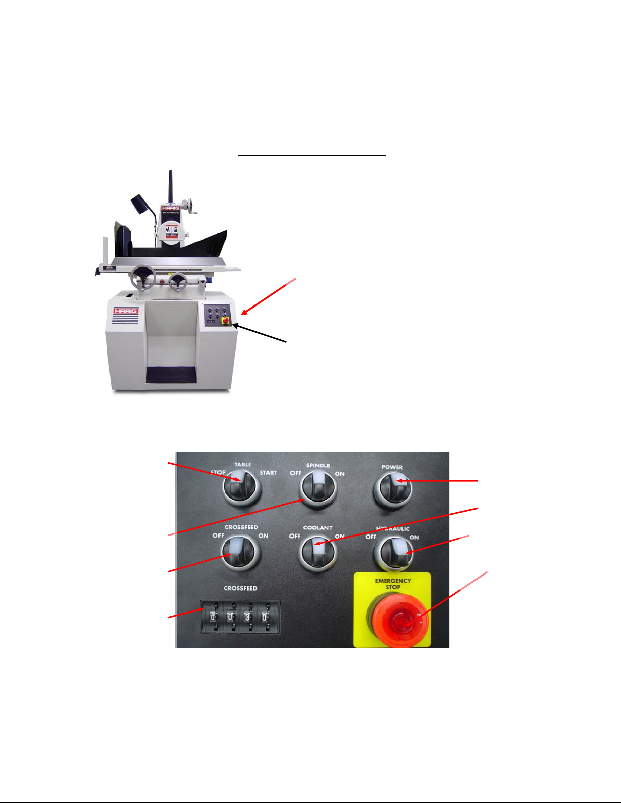
AUTOMATIC DIAGRAMS
The main Power switch is located
on the right side of the stand.
Be sure to have this switch turned
“ON”, then momentarily turn the
Power
On/Off
“Power” switch on the front panel
to the right to begin operation.
Switch
Front
Panel
Table
Spindle
Crossfeed
Crossfeed
Thumbwheel
Power
Coolant
Hydraulic
Emergency Stop
6

INSTALLATION
Step 1. Do Not Remove the Skid
Do not remove the skid until the machine has been moved adjacent to its installation site.
Step 2. Lift the Grinder From the Skid and Position
Before moving the elevating hand wheel (Fig. 2, B) to remove the wood brace between the table
and spindle housing, remove the plastic temporary dust cover from the top of the column and
slowly pour 2 ounces (1/4 cup) of way oil (the gallon container in the “standard accessory box”)
over the bevel gear.
2.1 Place a ¾” steel bar through holes near bottom of grinder base.
2.2 Attach an 1800 lb. lifting strap to the ends of the bar and join near the top of column. Strap to
the top of column. Pad the machine adequately to prevent damage to finish (Fig. 1)
2.3 Remove the four ½-20 head bolts holding the base cabinet to the skid. Caution: Do not lift by
the motor, spindle, table or saddle.
2.4 Lift slightly from the skid. Loosen the cross feed lock thumbscrew (Pg. 10, Fig 6). Balance
the machine by turning the cross feed hand wheel. For safety, support the machine on two 4ft.
pieces of 4 x 4 while installing leveling legs.
2.5 Screw the 4 leveling legs (located in “standard accessory box”) into the holes in the base of
the cabinet to project 5/8” below the bottom.
Step 3. Position the Machine
Position your machine where desired. No special pad, floor reinforcement or drip pans are
required.
Step 4. Clean the Machine
Remove the grease from table hand wheels and exterior surfaces with clean rag. It is not
necessary to disassemble anything, as all interior surfaces are factory prepared. Do not use
solvents or abrasive that may damage machine’s finish.
Step 5. Level the Machine
5.1 Crank table all the way to the right and all the way toward the column.
5.2 Raise the left front leveling leg ¼” off the floor.
5.3 Place a level on the table platen and adjust the three remaining legs to level the table in both
directions.
5.4 Lower the left front leg to floor and give it an additional 1/8” turn.
Step 6. Assembly
Use (3) round head screws (furnished) to fasten Elevating Screw Guard to Column Cap (Fig. 2,
A)
A
B
7

Step 7. Wet Coolant
Assemble as per instructions packed with the system.
Step 8. Lubrication
8.1 If needed, fill the lube oil reservoir. (Cup at rear of machine). Add way oil from the gallon
furnished to bring the level to up to nearly full. (Fig. 3)
8.2 Ways and feed screws are automatically lubricated.
8.3 Spindle and motor bearings are permanently lubricated.
8.4 The rack and pinion longitudinal table drive was greased at the factory. Add small amount of
grease to the rack each month.
Step 9. Electrical Connections
CAUTION: To prevent personal injury, or extensive machine damage, all electrical services
must be performed by an authorized Harig
® distributor.
Violation will void the warranty.
9.1 Ground the machine by connecting the green wire to a satisfactory ground. Neither the
building structure nor a hot water pipe is a satisfactory ground.
If a satisfactory ground is not available, drive an 8-foot copper ground rod into the ground and
securely clamp the ground wire to it.
9.2 Compare the rating label on the back of the spindle motor with your house current to make
certain they correspond.
9.3 Turn the main power disconnect handle to the “OFF” position and loosen the ¼ turn screws.
Open the control compartment.
CAUTION
any connectors to electronic logic units. Failure to observe this precaution may result in
permanent damage to the unit.
9.4 Bring the main line through the knockout on the back of the cabinet. Connect to the top of
the fused disconnect block.
9.5 Remove the wheel from the spindle.
9.6 Stand in front of the machine and turn the spindle motor ON. It should ROTATE
CLOCKWISE. If not, switch any two line wires to fused disconnect block. (DO NOT switch
motor leads, as this will damage hydraulic system by making it run backward.)
: Make sure the machine disconnect is turned OFF before plugging or unplugging
Fig. 3
8

SPINDLE MOTOR-OIL PUMP
The spindle motor is turned on by momentarily turning the “Spindle” button towards the ON
position. This also starts the oil pump of the lubricating system. After ½ minute the oil level
should rise to the mid-point of the sight glass in the column cap of the machine. The spindle and
oil pump are stopped by momentarily turning the “Spindle” button towards the OFF position, or
pressing the “Emergency Stop” button. (Pressing the emergency stop button will also stop the
hydraulic and cross feed system motors if they are running.)
MACHINE OPERATION- POWER ON
Turn the main switch clockwise to apply power to machine. (Be sure the “Emergency Stop”
buttons are not illuminated.)
LONGITUDINAL FEED
Warning: When first starting the table to run automatically, make certain the proximity sensors
are between trip dogs. To connect the powered longitudinal feed, crank the table to right as far as
it will go. Bring the locking lever (Fig. 4, A) forward and down into the pilot nut on the end of
the cylinder rod. Be sure the lever is seated all the way into the groove. Adjust the two dogs (Fig.
5, C) to within a few inches less than the desired table travel. Turn the hydraulic button towards
the ON position. Disengage the handwheel by loosening the thumb screw (Fig.4, B) on the left
side of cross travel saddle and pull the longitudinal feed handwheel out about 1-1/4 inches
(Fig.5, A). Momentarily turn the “Table” button towards the ON position. (The handwheel
electrically locks out the hydraulic feed when engaged.) Once the table is started, the control
will keep track of directions and reversals until the main disconnect is turned off, even if the
proximity switch is tripped while moving the table manually. The table will now power feed
(back and forth) at a speed determined by the speed control knob. (Fig. 5, B). The maximum
feed rate will be 70 feet per minute. Turning the knob clockwise reduces the feed rate. When
grinding a piece at the full length of the chuck it may be necessary to readjust the table reversing
dogs, to prevent the table from hitting the internal table stop. To convert grinder back to hand
feed, stop the table by momentarily turning the “Table” button towards the OFF position. Turn
off the hydraulic system by momentarily turning the “Hydraulic” button towards the OFF
position. Re-engage handwheel. Crank table to right until the table hits the internal stop. Lift up
the locking lever (Fig. 4, A) to clear the pin and flip it back to its disengage position.
Note: The speed control valve should be rotated fully counterclockwise in order to permit
manual movement of the table via the longitudinal feed handwheel. It is a good practice to
distribute oil evenly over entire length of ways before using grinder. Simply turn on spindle and
run table back and forth a few times. (The “Spindle” control activates oil pump.)
Fig. 4 Fig. 5
9

B
A B C
CROSS FEED
CAUTION: To prevent damage, check the location of the adjustment dogs below the right side
of the table. The dogs must be set very far apart for manual use and as close as needed for
automatic Crossfeed use.
Achieve manual cross feed by loosening the cross feed travel locking thumb screw (Fig. 6 A) on
the right side of the base under the table one turn, and operating the cross feed hand wheel. (Fig.
5 D)
For automatic operation of the Crossfeed, turn the “Crossfeed” switch towards the ON position.
Set your Crossfeed step size by rotating the thumbwheel from .0001” to .9999”. Turn the switch
towards the OFF position to run the Crossfeed manually again.
COOLANT/ WET GRIND
Your grinder may have come with a Coolant System. Once installed, your Wet Grind
will turn on by turning the “Coolant” switch towards ON.
ELEVATING MECHANISM- DOWNFEED
Raise or lower grinding head assembly by turning handwheel (Fig. 7, A) on the right side of the
top of the column.
To change zero setting, loosen two knurled screws (Fig. 7, B) projecting from face of wheel,
slide calibrated slip ring to desired position, and retighten screws.
To engage “fine feed” (optional equipment), tighten one large knurled screw. (Fig.7, C) One
revolution of the “fine feed” knob changes elevating screw setting by .001 inches. To disengage
“fine feed”, loosen knurled screw ½ turn.
Fig. 6 Fig. 7
TABLE PARK
A
B
A
C
10

You may park the table at any time during a cycle. Simply turn the table switch to the
OFF position and hold for two seconds.
CHANGING THE DIRECTION OF THE TABLE PARK
The table park is set to park towards the right as a default on your grinder. To change
the direction of the park turn the “Hydraulic” switch and the “Table” switch to the OFF
position at the same time for four seconds. The table light will flicker for about 8
seconds, and then the change will be complete.
GRINDING WHEEL MOUNTING
Use only balanced wheels to ensure getting the maximum quality this precision machine is
capable of producing. When specific problems regarding wheels selection are encountered,
contact a grinding wheel manufacturer or its local representative for recommendations.
The spanner wrenches (furnished) fit the wheel hub nut, which holds the grinding wheel on the
adaptor, and the two holes in the back of the adaptor. Unless a right-hand thread has been
specifically ordered, the wheel hub nut has a left-hand thread (letters LH stamped on face of nut)
so that the wheel will tend to tighten under starting torque. When changing wheel, be sure
adaptor is retightened. If left loosed, wheel may shift and cause chatter marks.
The socket on one spanner wrench fits the nut holding the adaptor on the spindle. To remove
adaptor, unscrew nut completely (left-hand thread) and screw in the “puller” (furnished) until the
center screw hits the spindle end. Tighten center screw until adaptor is free. (Fig. 8)
GRINDING MAGNETIC CHUCKS
A magnetic chuck with an untrue bottom can distort a surface grinder table to which it is
clamped. For this reason, the bottom should be wiped dry, placed on a surface plate and checked
for bow. If the chuck rocks or pivots rather than having an even drag, place it face down on the
platen and grind the bottom flat. If a surface plate is not available, use the grinder’s platen.
CAUTION
Grinding the chuck surface requires special technique and great care. The “lead” filling between
the magnetic poles tends to load the wheel and will cause the unsupported areas of the chuck
over the magnet to move with any temperature difference created by grinding. Follow these
instructions carefully:
1. Use a relatively coarse grit wheel of medium grade and open structure with a vitrified bond.
: Never grind the platen, as this can impair accuracy.
Fig. 8
11

The 9A-46-H8-V52 wheel furnished with the machine works well if used with a mist or wet
coolant and can be used dry if care is used to prevent heat buildup. If difficulty is experienced,
use a still softer and more open wheel such as a 32A46-G12BEP.
2. Dress the wheel rather coarsely with a sharp diamond. Cross feed the diamond at a fairly rapid
rate (15 in./min.) and do not pass under wheel unless down feed at least .0005 inches. Tighten
the screws holding the chuck to the table with minimum force needed to keep chuck in place.
Over tightening may cause warping.
3. The chuck must be in the “on” position while being ground.
4. It is best to grind the chuck with hand feeding so any increase of cut caused by heating can be
detected. If power feeding, use ¾ of maximum speed. (52 ft./min.)
5. Take a cross feed cut of at least .060 inch for each pass, and set the depth of cut to .0002 inch.
6. Dress the wheel after each cut across chuck to remove any “lead”.
7. A loaded wheel, whether caused by heavy cuts, improper dressing or the wrong type of wheel,
can create heat building sufficient enough to warp the center of the chuck up into the wheel and
seriously affect chuck flatness.
PROPER TORQUE FOR CHUCK MOUNTING
MAXIMUM TABLE WEIGHT WITH MAGNETIC CHUCK
612 Steel, Turcite or Plain Ways: 160 Lbs
Left, 15 Ft.lbs
Fig 9
618 Steel, Turcite or Plain Ways: 200 Lbs
Right, 10 Ft.lbs
MAINTENANCE
This precision surface grinder is equipped with an automatic “Flo-Clean” oil system. Unlike any
other grinder, this completely separate system circulates, filters and re-circulates the
cleaning/lubricating oil. All moving mechanical and wear surfaces are automatically and
continuously flushed with filtered oil whenever the spindle is running.
12

C
leaning
This machin
built-in system mentioned above. When cleaning the external surfaces:
1
. Center the table to prevent swarf and grit from being brushed onto the ways.
2
. Never use an air blast to clean the machine. Use a vacuum and/or treated dusting cloth.
Remove material and wheel grit, rather than just moving it.
3
. Make certain the exhaust from a vacuum or dust collector is not directed toward the grinder
and particularly not at underside of table.
4
. If solvents must be used to clean surfaces, use caution not to drip on the ways. Do not use a
lacquer base or other solvent, which may damage the machine’s finish.
Note: we recommend centering the table when the machine is not in us
for the table ways.
e requires only surface cleaning. All internal parts are cleaned automatically by the
e to provide a dust cover
ubrication
L
Since the mo
maintenance required are the following periodic checks:
aily:
D
Check th
Way Oil (Part No. 16211245, furnished with machine) to bring level nearly full.
E
very 100 hours of operation:
Check hydraulic tank oil level. R
turn screws. Sight gauge should indicate at least above the halfway point. If not, add Harig®
Hydraulic Oil (Part No. 16211213) (Viscosity 115 SUS) to bring the level to full.
C : Using anything other than Harig® Way Oil (Part No. 16211245) will void the
AUTION
Warranty
E
very 1000 hours of operation:
Clean the oil pump filter. Unscrew
from sump. With pump up side down remove the retaining clip from filter cup (be careful not to
puncture screen) and remove screen. Clean pump, screen and sump, and reassemble and refill
with new way oil.
tor and drive are permanently lubricated and sealed, the only lubrication
e large oil cup in the rear of the machine. If it is less than half full, add enough Harig
emove back center plate of base cabinet by loosening four ¼
.
dust guard retaining screw and remove guard. Remove pump
®
C
heck hydraulic pump filter. Remove back center panel. While the pump is running, examine
filter restrictor gauge (left side of manifold assembly). During normal operation the gauge should
indicate in the green zone. A red zone reading indicates the filter is clogged; remove it and clean
with a solvent by flushing from the outside in. replace filter and change the hydraulic oil
(approximately 4 gal.)
E
very 5000 hours or two years of operation:
Replace hydraulic oil and clean filter.
C : To protect system pressure gauge, close valve except when taking pressure
AUTION
reading.
ROUBLESHOOTING
T
13

djustments
A
Your Harig® s
urface grinder has been designed to give a long life of accurate finish
surface grinding. It has been thoroughly checked during manufacturing and final
assembly, and has been run-in and given a performance test.
T
he following section is set up to assist you in getting maximum performance from the
machine. Each trouble or malfunction is listed followed by possible causes, together
with suggested adjustments or changes you can make. The subjects addressed are:
Problem:
Page Number:
1. Chatter or Vibration Marks in Finish 14-16
2. Longitudinal Lines—Scratchy Finish 15
3. Inaccurate Grinding 16
4. Motors Do Not Run 17-18
5. Oil Dripping 18-19
6. Uneven Down feed Response 19-21
7. Improper Longitudinal Feed 20-21
8. Crossfeed Malfunction 21
1. CHATTER OR VIBRATION MARKS IN FINISH
. Wheel loose on sleeve.
A
Put additional tension on wh
be causing wheel to shift slightly. Redress after adding tension to the wheel nut.
B
. Wheel out-of-balance.
All grinding wheels are out o
by holding the projecting part of the spindle housing while the grinder is running with the wheel,
wheel nut and washer removed, and by comparing the vibrations with the wheel mounted in
place.) Balance the wheel with a Harig® Wheel Balancer (No. 17794350) or comparable uni
If
the wheel has not been balanced, the chatter can be minimized by dressing the wheel at the
grind point and taking a finishing cut that puts the same drag on the wheel as the dressing
operation. The wheel is dressed out-of-round to compensate for the amount of vibration. I
heavier cut is taken, however, the chatter will occur because of the “ hammering” of the out-of
round wheel at a different vibration rate. If a Harig® Accu-Dresser is used to dress an
unbalanced wheel, chatter in the finish will result because the wheel is dressed round an
“hammer” by the amount of vibration. A balanced wheel will give you more cycles between
dresses because of the elimination of this “hammering”.
C
. Wheel not dressed on Sides.
If the wheel has not been dressed
the side-to-side movement of the edges of the wheel, and because the outside surfaces of a wheel
next to the mold are harder than the rest of the wheel.
D
. Wheel in need of dressing.
If chatter appears after the wheel
grinding wheels vary in hardness around the periphery. Since this chatter appearance is usually
eel adapter nut. Even if nut is not loose, motor starting torque may
f balance. It is only a question of how much. (One can verify this
t.
f a
-
d will
on the sides, a chatter or vibration pattern can result because of
has been used for a time, it is probably due to the fact that most
14

only a few millionths of an inch high, weigh the economics of the more frequent wheel dressing
against the slight loss of appearance.
E. Loss of preload.
ccasionally, due to a phenomenon called fretting corrosion (usually caused by out-of-balance
O
wheels), the rear bear
longer hold the spindle shaft tightly back against the front bearings. To check for loss of
preload, place an indicator against the spindle nose. Push against wheel guard with thumb
p
ulling wheel forward with fingers while watching indicator. When released, the needle should
instantly return to original position. If needle will return to original position only by rotating
wheel by hand, return spindle to factory for repair. Be sure to state that there was a loss of
preload on this test.
F. Grade of wheel to
L
oading up or glazing of the wheel, particularly if grinding without coolant can cause chatter.
Replace wheel with one of a so
G. Taper of adaptor sleeve in error.
If
the taper in the wheel adaptor sleeve is not the same as that on the spindle nose, or if a piece of
dirt or grit has been assembled on the ta
sleeve by putting a thin film of Prussian blue inside the sleeve and press it on the spindle. The
spindle taper should show contact all around the circumference on two separate rings.
H. Ball bearing failure.
T
he super precision bearings used in the Harig® spindle are sized to give many years of service.
If a failure of either the sp
being ground, and a noise will be heard when the spindle is running. (Wheel, wheel nut and
washer should be removed to make certain an unbalanced wheel is not causing the noise.)
Replacement of all bearings on the spindle assembly, or a new motor, is required. It is
recommended that the spindle assembly be returned to the factory for repair so that the dyna
balance of the unit can be checked.
I. Unbalanced electric supply.
If
the 3-phase current supplied to the machine is not reasonably uniform, a poor finish will result.
J. Use of phase converter.
A
phase converter used to run a three-phase motor on a single-phase supply will also affect
finish and motor sound beca
The type of converter that switches out of the circuit after starting the motor will cause a poo
finish than a single-phase motor. The type of converter that stays connected, an
only the spindle motor, will give a better finish than a single-phase motor.
ing outer race will freeze in the spindle sleeve and the wave springs will no
s,
o hard.
fter grade.
per, a chatter can appear on the work. Check the adaptor
indle or motor bearings does occur, chatter will appear on the work
mic
use of the unbalanced current a converter delivers.
rer
d is rated to run
2. LONGITUDINAL LINES- SCRATCHY FINISH
A. Wheel is too soft for material being ground. Grains in too soft a wheel pull out before they
h
ave really dulled. The dressed surface will be lost quickly and the few remaining pointed
grains give a scratched appearance. Replace with a harder wheel.
B. Wheel dressed too finely, or wheel too hard.
If
wheel is not cutting freely, longitudinal lines in the finish, sometimes a discolored or burnt
finish will result. Replace with a softer grade whee
faster speed when dressing. Do not dress the wheel without a down feed before each pass.
l or pass the diamond across the wheel at a
15

C. “Hard-shell” sides on wheel.
Break the corners of the grinding wheel with an abrasive stick.
D. Grinding swarf in coolant.
Clean out coolant tank.
3. INACCURATE GRINDIN
G
. Magnetic chuck clamped too tightly or too loosely.
A
A chuck or fixture clamped too tightl
ra
ther than tracking smoothly. If chuck is not clamped tight enough, it could shift position and
lift up and over dirt. Tighten one of the clamps firmly to h
tighten the other clamp only enough to keep the chuck down on the table.
B. Wheel glazed and not cutting freely.
Redress the wheel, or replace the wheel with a softer grade.
C. Machine out-of-level.
Be sure that the cast stand is level. The thickness of the four
th
e grinder on the cast stand has been adjusted to support the grinder base so that the plane of the
V-ways are exactly paralle
anything other than its own cast stand and vibration isolation pads, check base ways for twist by
laying a small surface plate on two 1.000-inch rolls in the V-ways and add two .582” +/- .0002”
parallels on the flat ways of the base. If the two rolls are placed in the ends of the V-way
one of the parallels put in the center of the flat way, the height of the pads should be adjusted
until one gets the same “feel” at either end of the flat way with the other parallel.
D. Magnetic Chuck in need of dressing.
See “Grinding Magnetic Chucks” in operating instructions.
E. Grinding Wheel shifted in adapter.
If the wheel is not tight enough on the adapter, it can shift w
o
r when a heavy cut is being taken. This could cause the grinder to cut an additional few
thousandths, as well as giving a chatter ap
F. Down feed inaccurate.
See section “Uneven Response in Down Feeding”
G. Side grinding not square.
If the cartridge spindle has been replaced, it will be
b
y adjusting the tension of the five set screws that hold the spindle cartridge in place.
To check the squareness of the spindle to longitudinal travel of the table, an angle plate can be
indicated parallel to the table travel, and an indicator fastened to the nose of the spindle
b
e swung. If this indicator has a higher reading for the right-hand position tighten the upper
right and lower left set screws on top of the spindle housing to shift the spindle slightly.
The angle plate can also be used to check the spindle axis parallelism to the work table. Vary
the tension applied by the bottom set screws, against the tension of the four top set screw
c
hange this indicator reading slightly.
l with the plane of the flat ways. If grinder base is located on
y may warp the table, causing it to rock in the saddle ways
old the chuck in position. Then
vibration isolation pads that support
s and
hen the grinder is turned on and off,
pearance on the surface.
necessary to realign the spindle in its housing
can then
ing
s, can
16

H. Work piece not parallel.
If the machine does not grind parallel front-to-back, be sure the cross feed lock screw has been
loosened enough so the pressure is not
I. Long spark out time.
If the grinder does not “spark out” after a reasonable number of passes, you may be using an
incorrect viscosity oil, use only (Harig® Way Oil) 16211245 The pressure oil
th
e ways with so much oil that a higher viscosity lubricant can lift the table a few tenths when
light cuts are taken.
rubbing on the carriage-locking strap.
ing system floods
4. MOTORS DO NOT RUN
A. Disconnect switc
If
“ power-on” panel light is not lit, be sure disconnect switch on control compartment door is
turned on.
CAUTION:
machine damage. All electrical service must be performed by an authorized Harig®
distributor
B. Fuse blown out.
If more than one motor will not run, if a motor runs slowly, or if “power-on” light will not turn
on, one or more fuses may be blown. There are th
p
lus one or two circuit fuses mounted on or next to the transformer. First check lines leading to
the machine to make
equal, or not more than 10% higher amperage. If a single element fuse is used for replacement,
be sure it is rated at 3 times the amperage of the dual element fuse.
On rare occasion a fuse will blow under normal machine usage. If a fuse bows repeatedly,
however, the cause must be found and corrected.
(A stalled motor can blow a fuse before the overload heaters of
in
spect control compartment and motor wiring for loose connections (particularly in the motor
connection box) and for worn through insulation, causing grounding out to the machine frame. If
machine is equipped with a coolant system, exc
onto the cabinet and dripped into the hydraulic motor or sockets on the back of the machine.
C. Overload relay tripped.
The spindle, hydraulic pump, oil pump, and coolant (optional) motors are protected with
overload relays or fuses in the control cabinet. If any motor is overloaded for a period of time,
verload relay or fuses will shut it off. (If either the spindle relay or the lube pump fuses trips, it
o
will shut off the hydraulic p
mounted on the motor starters (1M, 2M, etc.)
If only the spindle motor overload is tripping, chances are the grinding wheel is taking too heavy
a cut, or that the wheel is loading up, putting extra strain on the motor. A 2HP motor will have
enough power to take as heavy a cut as the ope
c
oolant is not being used. If cross feeding with coolant, or plunge grinding, it is easy to take a cut
that requires more power. Under these conditions, check spindle motor current consumption to
make sure it is not exceeding full load motor current shown on nameplate before adjusting the
overload relays.
Overload relays are installed set for automatic reset. If overload trips, it will reset after it cools.
To change to manual reset, depress and turn the blue button until the slot aligns with the letter
Electrical connection or services to preclude personal injury or extensive
. Violation will Void the Warranty.
h not turned on.
ree (3) main fuses mounted on the disconnect,
sure plant circuit fuses are not blown. Replace fuses with delay type of
the motor starters kick out.).
ess coolant may have overflowed or splashed
its
ump, the spindle and the lube pump). The overload relays are
rator normally wishes if table is cross feeding and
17

“H”. if nuisance tripping is occurring due to a higher ambient temperature, the trip point may be
raised slightly by
only after determining that the motor is not drawing higher than nameplate current. If current
draw is excessive the problem is in the motor, not the overload.
D. Motor burnt out.
All motor used on your grinder have a design life of many years. The motor most likely to fail is
the oil pump motor because it depends on the oil level bei
o
verheating. A burnt out motor will usually draw an excess of current and trip the motor
overloads, blow fuses,
and cause a wire to break loose. Checking motor circuit with an ohmmeter should locate any
internal breaks. An ammeter check on motor current on each of the three legs of a three phases
motor will show a shorted out section of winding by drawing more that the rated full load
current.
A maximum temperature at which a motor can be safely operated depends on the class of
insulation of its windings.
A
motor stamped class A can reach a temperature of 203°F on its shell; Class B can reach a
temperature of 239°F, and still be within the manufacturer specifications.
E
. Electrical Discontinuity.
If all above checks have been made and one or more motors still do not run, check motor starters
and control panel wiring. Open control compartment and visually che
c
onnections. Check motor power circuits by visually turning current on and pushing in the motor
starter solenoid with a fully in
CAUTION
machine damage. All electrical service must be performed by an authorized Harig®
distributor Violation will void the warranty.
If motors run, check control circuit by turning off current and using an ohmmeter to check
control-wiring continuity against the electrical diagram. (The most likely cause of an open circuit
would be the starter solenoid coil or a faulty ove
If the motor does not run with the starter solenoid held in, turn off current and check power
circuit continuity.
Tighten all loose fitting. Replace any defective hose or tubin
sa
ddle in order to get at the hydraulic fittings, lift table off the saddle.
The hydraulic hose
out of the compartment and placed in a position to allow the saddle to be handled within a range
that the hose will flex.
If
hoses are removed, tag them so that they can be reconnected to their proper fittings. Then
crank the saddle all the way up to the column. Remove the screw in the end of the cross feed
hand wheel, loosen setscrews in the side of the hand wheel and pull the hand wheel off its shaft.
Now pull the saddle forw
feed screw shaft. Remove the tubing connector that fastens the lubricating oil line between the
base and the saddle from the saddle fitting. The saddle can now be lifted off the machine.
turning the black dial on the overload relay to slightly higher number. (Do this
ng maintained to keep it from
or overheat in one spot. It may, however, overheat an internal connection
ck for loose wires or
sulated screwdriver.
: Electrical connection or services to preclude personal injury or extensive
rload relay.)
g. If it is necessary to remove the
s may be removed from fittings on the carriage, or the hydraulic unit taken
ard until it hits the cross feed stop, which pulls the bearing off the cross
18

The entire underside of the table, saddle and the ways in the base and saddle should be carefully
cleaned before reassembling the machine to be sure that grit cannot fall into the way whe
nd saddle are being put back into place.
a
n table
5. OIL DRIPPING
A. Machine not level.
The machine being improperly
w
ays. Re-check leveling, and follow installation instructions if machine is not level.
leveled can cause oil dripping from the underside of the table
B. Restricting valve open too wide.
Check restricting valve setting. Remove dust guard (Part No. 16816608) by loosenin
sc
rews and sliding the guard up so that the screw heads will pass through the keyhole slot in the
guard. Reset the valve by closing it do
wn completely and then reopening 1/2 turn. If dripping
from the ways continues, close the valve back to the point where it is opened approximately 1/8
g the two
of a turn.
6. UNEVEN DOWNFEEDING RESPONSE
A. Wheel too loose.
If grinder has been stopped and restarted with the wh
ifted slightly when the motor was restarted, cutting an additional amount because of being off
sh
center. Retighten grin
ding wheel.
B. No oil on column ways.
Check oil level in sight glass at the
o
il does not appear, make sure that oil cup on the back of the machine base is nearly filled. Add
oil if necessary (Harig® Part
top of the column shortly after spindle motor is turned on. If
No. 16211245). If oil is at the proper level, see that the pump is
running and that filter screen is clean. (See LUBRICATION under MAINTENANCE.) Check
that oil lines are intact and on their proper fittings.
C. Spindle housing assembly sticking in column ways.
The exceptional rigidity of the Harig® Grinder is ob
c
olumn ways. Since there is only a few tenths clearance between the spindle housing and
column, any dirt, grit, or a very small warping of the back
“hang up” in the ways. Check for this condition by mounting an indicator on the wheel gua
spindle housing to touch a block on the grinder table. Turn the down feed hand wheel and
the response on the indicator. The 100 lb. combined weight of the motor spindle and housing
and guard assembly should keep the lock nut carrying the elevating screw firmly seated in the
ball bearing in the column cap.
To inspect column ways, remove the grinding wheel from the spindle. Then remove the wheel
guard by loosening its clamping
5
/16” set screws holding the spindle cartridge in the housing approximately 1/8”. The spindle
screw and sliding it off the end of the spindle. Loosen the five
cartridge and motor assembly can now be removed from the back of the machine. Take out the
six Phillips head screws that hold the back dust guard retainer in place, and remove the dust
slides and retainer. Crank the saddle away from the column and remove the six Phillips head
screws holding the front dust slides. Now alternately crank the spindle housing to the top and
then to the bottom of the travel, wipe off the ways with a clean cloth and inspect. Clean any
or grit. Check to see if a piece of grit has scored the ways. If so, they should be dressed with a
fine stone to remove any ridges.
eel insufficiently tight, the wheel may have
tained by an extremely close fit on the
plate could cause spindle housing to
rd or
note
dirt
19

If the column way surfaces are clean and smooth and the spindle assembly is still sticking, either
the spindle slide back plate has w
fe
w tenths. If the spindle housing is tight in only a small area, scrape the back ways of the
arped or the column uprights have moved closer together by a
column to remove the high spot. Applying a thin layer of red lead or blueing to the ways and
running the housing assembly up and down can find the high areas of the ways.
If the assembly is tight over the entire column, remove the back plate from the spindle housing
by taking out the six 5/16” screws holding it in place. Crank the spindle housing
p
osition and push the housing just far enough away from the column to inspect the 45-degree
to the bottom
ways.
If there is no evidence of scoring or a piece of grit lodged in the casting, grind .0003” off the tw
surface
th
s of the back plate that ride on the back column ways. Accurately check the step between
e way surface of the back plate and the center part that is screwed to the spindle housing before
grinding the way surface, so the entire back plate can be reground if found to be warped.
Reassemble the back plate to the spindle housing. If still too tight, remove an additional .0003”
from the way surface.
D. Spindle housing too loose.
If the error in down fee
lo
ose in the column ways. Remove the motor spindle assembly and dust guards as outlined in
the previous section. Determine
d response is less than .001”, the spindle housing assembly may be too
the amount of looseness by placing an indicator on the grinder
table to read against the part of the spindle housing projecting to the front of the grinder. With
the column ways wiped clean of oil, alternately twist the spindle housing from one side to the
other. The difference on the indicator reading when the twisting pressure is released should be
less than .0005”. Make this check at both the top and bottom positions of the spindle housing, a
well as in the middle, and use the lowest reading. Remove the back plate from the spindle
housing. Then remove 3/4 of the difference between the “at rest” indicator readings from the
center area of the back plate that is clamped against the spindle housing. For example, if .0012”
slack is found, remove .0009” from the center area of the plate.
7. IMPROPER LONGITUDINAL FEED
A. Table runs slow or stops.
See that the hydraulic pump is running in the dire
th
e motor is turning in the wrong direction, check to make sure the spindle motor is turning in
the proper direction. If not, rev
erse any two of the line wire connections to the machine. If the
pump motor is turning in the correct direction, make certain the speed control valves are open
and the table drive hand wheel is pulled all the way out. If the table still will not start, the
following checks may be used to determine the problem.
If the machine had just been set up, check the hose connections to the pump and to the mac
to make sure that they are connected properly.
Check the hydraulic pressure by opening the control valve next to the gauge while the pump is
running. Start the table, and then close the tabl
b
e7 250 PSI.
NOTE: Gauge should be turned off when not in use.
If the pressure is too low, adjust accordingly. If the pressure is correct, remove the screw on the
ction indicated by the arrow on the motor. If
hine
e speed control valve. The pressure should be
move while the plunger is depressed. end of one solenoid and move plunger. The table should
o
s
20

Release plunger before reaching end of travel. If the table will not move by dressing the plunger
(Note: Plunger is difficult to push), the valve should be replaced. If the table travels by manually
activating the solenoid, proceed to the electrical checks.
B. Jumpy table movement.
If
the grinder is being operated at a very slow speed (speed control valv
irregular movement or “jump”
may be seen. If the grinder has not been operated for a long
e turned way down), an
period of time, this may be due to air in the cylinder. The air can be removed from the cylinder
by setting the table travel for an 8 inch stroke and operating the table at full speed for a short
period of time.
Insufficient lubrication of the longitudinal ways can also cause this problem. More oil can be
fe
d to the ways by opening the restricting valve an a
dditional 1/3 turn. Running the table back
and forth a few times before taking a cut will help distribute the oil evenly over the ways to
minimize this condition.
8. CROSS FEED MALFUNCTION
A. Normal Operation.
A module turns on the stepping motor. The feed
utomatic cross feed occurs when the electric
cycle is started when th
direction. Cross feed continues until the electronic module has moved the stepping motor the
correct number of steps; each step equal .0001”. The feed distance can be set from .0001” to
1.0000” in .0001” increments.
NOTE: If the table reverses before completing a cross feed, the electronic module will reset and
give a complete feed from that point. The force to turn the cross feed screw is transmitted from
the motor through the coupling to drive sleeve which has a square hole broached in its end. The
slip fit between this hole and the square shaft that is pinned to the end of the cross feed screw
allows the screw to travel back and forth with the saddle and still be driven by the stationary
motor. The direction of feed is control by the direction of rotation of the motor. Motor rotation is
changed by proximity switch and trip dog bracket.
B. Hand feed wheel turns hard.
B
e sure cross lock thumbscrew has been loosened
e hydraulic control output relay changes states as the table changes
21

1
HARIG
WAY OIL GAL. 16211245
PUMP
16211506 115VOLT
LUBRICATION SYSTEM

CROSS FEED LOCK-CLAMP ASSEMBLY
2

HYDRAULIC SYSTEM
SCHEMATI
psi
bar
100xkPa
HYDRAULICS
CONTINENTAL
SPEED CONTROL VALVE
17746556
3

SPINDLE AND ELEVATING ASSEMBLY
COUPLINGS 16213126
COMPLETE SPINDLE ASSEMBLY
2HP 16211375
3HP 16211418
4

5
ELEVATING SCREW AND HAND WHEEL ASSEMBLY
6
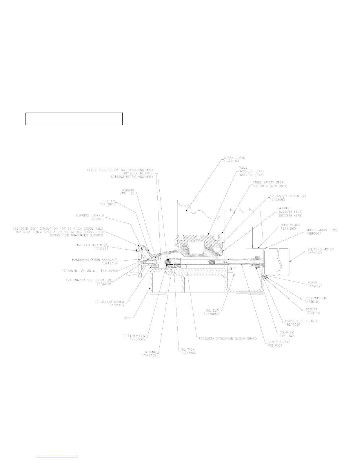
AUTOMATIC CROSS FEED ASSEMBLY

8
16815665 618 GRINDER
LONGITUDINAL POWER FEED

9 9
Oil filler cap
Table equalization
Valve
Pressure adjustment
valve
Oil level/temp gauge
Oil drain
Table park solenoid
Table park speed adjustment
Hydraulic oil 16211213
Hydraulic pump assembly 17746596
Pressure gauge
17746581
Filter
17746626
Filter gauge
17746579
 Loading...