

Hargrove H-Tube, S, 18SNHT0A0, 24SNHT0A0, 30SNHT0A0 Installation And Operation Manual
...
INSTALLATION AND OPERATION GUIDE FOR
HARGROVE
Glass H-Tube and
Stainless Steel “S” Burner
Installation and service must be provided by a qualified installer,
service agency or the gas supplier.
ADEQUATE FIREPLACE VENTILATION IS REQUIRED FOR SAFETY
NOTE:
The gas appliance must be burned only in a fully vented, non-combustible fireplace with the damper
completely open and the chimney free of any obstructions or restrictions. The fireplace must be designed and
approved to burn wood.
The realistic yellow flame produces carbon monoxide and soot. Under normal conditions, these products are
exhausted up the chimney. If fumes or soot, from the gas burning, are evident in the room when the damper is
fully open it indicates that the fireplace draft is defective. Do not operate your gas appliance until the fireplace
draft is corrected.
Do not store or use gasoline or other
flammable vapors and liquids in the
vicinity of this or any other appliance.
WARNING: If the information in this
manual is not followed exactly, a fire or
explosion may result causing property
damage, personal injury or loss of life.
It is the homeowner’s responsibility to
assure their fireplace has adequate draft.
READ INSTRUCTIONS FULLY BEFORE INSTALLING OR OPERATING
INSTALLER: LEAVE THESE INSTRUCTIONS WITH CONSUMER!
FOR YOUR SAFETY
FOR YOUR SAFETY
WHAT TO DO IF YOU SMELL GAS
1. Do not try to light any appliance.
2. Do not touch any electrical switch; do
not use the phone in your building.
3. Immediately call your gas supplier from a
neighbor’s phone. Follow the gas
supplier’s instructions.
4. If you cannot reach your gas supplier,
call the fire department.
1

IMPORTANT INFORMATION
WARNING: This appliance assembly contains burner orifices specifically for the input gas and
Btu rating. Modifying or failure to use the factory orifice may cause property damage, personal
injury or loss of life.
1. Do not use a natural gas set for propane or a propane set for natural gas.
2. There a many different local codes for gas appliances. The installation and the provision for combustion and
ventilation air must conform to local codes and, or in the absence of local codes, with the National Fuel Gas Code
ANSI Z223.1 – (most current revision).
3. Gas appliances must be installed by personnel qualified for installing gas appliances.
4. This appliance must be installed only in a solid-fuel burning fireplace with a working flue and constructed of
noncombustible materials. Solid fuels are not to be burned in a fireplace where a decorative appliance has been
installed.
5. A permanent free opening must be provided by either the fireplace chimney or chimney damper to vent flue gasses.
Any chimney damper must be fixed in a manner, which will maintain the permanent free opening at all times. Use
Table II to determine the minimum permanent free opening based on chimney height and the appliance Btu input
rating. Refer to the Damper Stop section for additional directions.
6. The minimum free opening is based only on two factors; chimney height and Btu input rating. Many other factors affect
the fireplace drafting. It is the homeowner’s responsibility to assure their fireplace has adequate draft. If fumes or soot
from the gas burning are evident in the room when the damper is fully open, it indicates that the fireplace draft is
defective. Do not operate your gas appliance until the fireplace draft is corrected. Consult your fireplace specialist.
7. A fireplace screen must be in place when the appliance is operating and, unless other provisions for combustion air are
provided, the screen shall have an opening(s) for introduction of combustion air.
8. When glass fireplace doors are used, always operate your gas appliance with the doors fully open to allow for proper
combustion air and to keep control valves from overheating.
9. The minimum inlet supply pressure for the purpose of input adjustment is 5.0 inches (natural gas) 11 inches (propane
gas) in water column. The maximum inlet supply pressure is 10.5 inches (natural gas) 13 inches (propane gas) in
water column.
10. The appliance and its individual shut-off valve must be disconnected from the gas supply piping system during any
pressure testing of that system at test pressures in excess of 1/2 psig (3.5kPa). The appliance must be isolated from
the gas supply piping system by closing its individual manual valve during pressure testing equal to or less than 1/2
psig (3.5kPa).
11. The fireplace chimney or venting system should be examined annually and cleaned as re quired by a qualified agency.
2
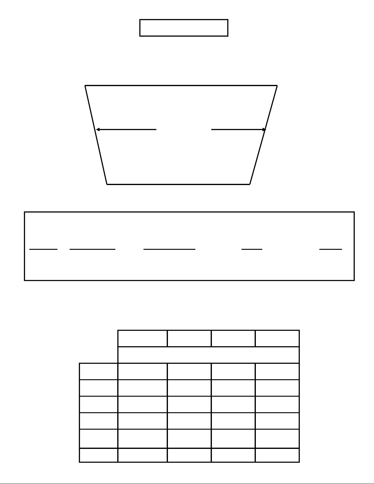
FIREPLACE SIZES
Each gas appliance requires a minimum 16-inch front opening height and minimum 16-inch depth. To
determine the largest set that will fit in a fireplace, the width at the center of the fireplace is the critical
dimension. Table I below indicates the minimum center width for each size set.
*View is looking down on the fireplace floor. To determine center width, add front width and
back width and divide by 2.
Minimum Minimum Front Minimum Minimum
Set Size Center Width Opening Width Depth Height
21 28” 30” 16” 16”
24 32” 36” 16” 16”
30 37” 42” 16” 16”
Front Width
Center Width
Back Width
TABLE I
TABLE II
Free opening area of chimney damper for venting combustion products from decorative
appliances for installation in vented fireplaces. Minimum size of chimney flue is 8” diameter.
Chimney
Minimum Permanent Free Opening, Square Inches
Height,
Feet
6 34,000 46,400 62,400 80,000
8 37,000 50,400 68,000 86,000
10 40,400 55,800 74,400 96,400
15 44,600 62,400 84,000 108,800
25 50,400 68,400 94,000 122,200
30 55,200 76,800 105,800 138,600
29 39 51 64
Appliance Input Rating, Btu Per Hour (w)
3
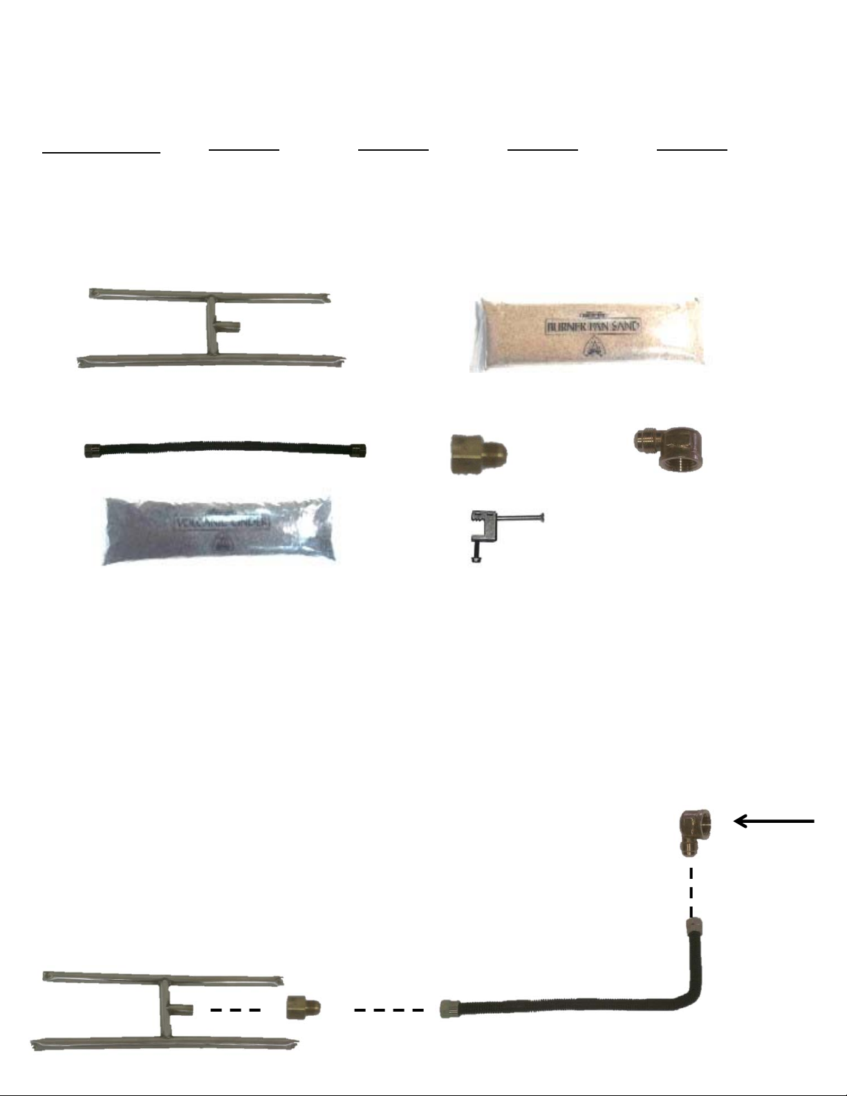
INSTALLING GLASS H-TUBE
PARTS LIST
ITEM DESCRIPTION
1. H-Tube
2. Sand
3. Flex connector
4. Brass reducing union
5. Brass reducing elbow
6. Volcanic cinders (3/8”)
7. Damper stop
1.
3.
6.
NATURAL GAS AND MATCH LIGHT ONLY
1. Make sure gas is shut off.
2. Connect the 1/2” to 3/8” brass reducing elbow (5) to your gas supply.
3. Connect the black flex connector (3) to the elbow (5).
4. Connect the 1/2" to 3/8” brass reducer (4) to the H-tube (1).
5. Make sure that the H-tube has the holes facing down. This will keep
the sand from obstructing the holes. This will not affect flame height.
6. Finally, connect the flex connector (3) to the brass reducer (4).
18SNHT0A0 24SNHT0A0 30SNHT0A0 36SNHT0A0
SSHB18 SSHB24 SSHB30 SSHB36
SD SD SD SD
FCNW-18 FCNW-18 FCNW-18 FCNW-18
46-6-8 46-6-8 46-6-8 46-6-8
50-6-8 50-6-8 50-6-8 50-6-8
VC VC VC VC
DS DS DS DS
2.
4.
5.
7.
GAS SUPPLY
4
 Loading...