

Page 1

HI 6600 Series Modular Sensor System User Guide
HI 6600 Series Modular Sensor System
User’s Guide
Hardy Process Solutions Document Number: 0596-0333-01 REV D
Page | 1
Page 2

Local Field Service
HI 6600 Series Modular Sensor System User Guide
Hardy Process Solutions provides local field service for all scales and weighing equipment. Hardy’s factory
trained technicians can perform service on all Hardy equipment as well as most other manufacturers’
systems. Enabled by the Hardy Process Toolbox, our technicians spend less time onsite, saving you money
and reducing your downtime.
Services Include:
• Installation & Commissioning
• Preventative Maintenance & Calibration
• Onsite Emergency Service
• Service Agreements with Defined Turnaround Times
• Product, Service, and PLC Integration Training
• Pre-Installation Site Audit
• Scale Installed-Base Evaluation
• PLC Integration Support
• Engineering Design Support & Specification Development
• Quality Documentation Creation
Contact Us
To request any of the services mentioned, or to discuss your needs with a trained Hardy Service Agent,
please call 800-821-5831 Option 4 (6:30 AM to 5:30 PM PST). For emergency downtime service after
hours, leave a message in our emergency mailbox and your call will be returned promptly
Page 3

HI 6600 Series Modular Sensor System User Guide
Contents
• • • • • •
Chapter 1 ......................................................................................................................................... 8
HI 6600 Series Overview ................................................................................................................ 8
Introduction to the HI 6600 Modular Sensor System.............................................................. 8
Typical Applications
HI 6600 Series Model Numbers
Chapter 2
Specifications and Features
Chapter 3
HI 6600 Hardwa re Installation
Chapter 4 ....................................................................................................................................... 29
Instrument Configuration
......................................................................................................................................... 11
Basic Specifications
HI 6610 Weight Processing Module (WPM) ................................................................. 11
Hardy Gateway Module (HI 6600) ....................................................................................... 12
Network Connectivity
Optional HI 6110 Front Panel Display
Environmental Requirements
Approvals ....................................................................................................................... 13
Network Certifications
Features and Capabilities
Hardy Process Toolbox
C2® Calibration
INTEGRATED TECHN I CI A N® ........................................................................................ 14
WAVERSAVER® ........................................................................................................... 14
Power Requirements for Configuring Your Modular Sensor System over Distance ............ 14
......................................................................................................................................... 18
Safety
..................................................................................................................................... 18
General Precautions
Unpacking ............................................................................................................................. 18
Tool List ......................................................................................................................... 19
Installing the HI 6610 Modules ............................................................................................ 19
Overview of the HI 6600 Hardware ...................................................................................... 20
Installation ...................................................................................................................... 21
Cabling the Units Together
DC Power Input .................................................................................................................... 23
Connecting Sensors ........................................................................................................ 24
Installing the Optional Display
Blind Unit (No display)
Optional Remote Display Mount
Mounting the Optional Front Panel Display .................................................................... 26
Making Longer Display Interface Cables
Using the Webserver ............................................................................................................. 30
.......................................................................................................... 10
.......................................................................................... 10
................................................................................................................ 11
................................................................................................................. 11
...................................................................................................... 12
.................................................................................. 13
.............................................................................................. 13
....................................................................................................... 13
........................................................................................................... 13
....................................................................................................... 13
................................................................................................................ 13
............................................................................................................ 18
........................................................................................................... 18
.................................................................................................. 22
.................................................................................................. 25
...................................................................................................... 25
......................................................................................... 25
............................................................................. 28
.................................................................................................................. 29
Page | 3
Page 4

HI 6600 Series Modular Sensor System User Guide
Using the HI 6110 Front Panel Display
Mode Button
Chann e l Identific ation
System Discovery
..................................................................................................................... 32
............................................................................................................... 33
.............................................................................................................. 33
.................................................................................... 31
Instrument ID ................................................................................................................. 34
Channel Identification .................................................................................................... 34
Deleting Channels
............................................................................................................. 35
Replace Channel ............................................................................................................. 35
Savi n g a n d R e s t o r ing Co n f i g u r a t i o n D a t a U s i n g t h e USB p o r t ......................................... 36
Suggested Minimum Steps When Setting Up the Instrument For the First Time........... 36
Setup Parameter Menus
Capacity Parameter
............................................................................................................ 37
.......................................................................................................... 37
Decimal Point Parameter ................................................................................................ 37
Graduation Size Parameter ............................................................................................. 38
Instrument ID ................................................................................................................. 38
Motion Tolerance Parameter .......................................................................................... 38
Operator ID Parameter
..................................................................................................... 38
Unit (of Measure) Parameter .......................................................................................... 38
Filter Parameter Menu
NumAverages Parameter
WAVERSAVER® Parameter
Calibration
.............................................................................................................................. 40
Pre-Calibration Procedures
........................................................................................................ 39
.................................................................................................. 39
........................................................................................... 39
................................................................................................. 40
Electrical Check Procedures .................................................................................................. 41
Load Cell/Point Input/Output Measurements ................................................................. 41
Load Check
C2 & eCAL Electronic Calibratio n
C2 and eCAL Calibration
Sensitivity Parameter
Ref Weight Parameter
Cal Tolerance Parameter
....................................................................................................................... 42
............................................................................................. 42
Commands and Parameters ....................................................... 42
........................................................................................................ 42
....................................................................................................... 42
................................................................................................... 43
Gravitation Correction .................................................................................................... 43
C2 Calibration Process
..................................................................................................... 45
Hard Calibration .................................................................................................................... 46
Hard Cal Commands and Parameters ............................................................................. 46
Cal Lo Weight Parameter
Cal Tolerance Parameter
Do Cal Lo Command
Do Cal Hi Command
Span Weight Parameter
Chapter 5
........................................................................................................................................ 48
Instrument Operation
........................................................................................................................ 48
................................................................................................. 46
................................................................................................... 46
....................................................................................................... 46
........................................................................................................ 46
.................................................................................................... 47
Operations ............................................................................................................................. 48
Tare Parameters and Commands
Tare Amount
Tare Offset
Tare Command
.................................................................................................................... 48
....................................................................................................................... 49
................................................................................................................. 49
Zero Parameters and Comm ands
Zero Tolerance
Zero Amount
................................................................................................................. 49
.................................................................................................................... 50
................................................................................................ 48
................................................................................................ 49
Page | 4
Page 5

HI 6600 Series Modular Sensor System User Guide
Zero Command
Auto Mode
Count Operations
Determining Piece Count:
................................................................................................................ 50
........................................................................................................................ 50
..................................................................................................................... 51
................................................................................................. 51
Chapter 6 ....................................................................................................................................... 52
Network Communications
................................................................................................................. 52
Maximum Number of Channels Supported for PLC Communication Formats ............. 53
LAN Connection ............................................................................................................ 53
IP address. ...................................................................................................................... 54
Enable DHCP
.................................................................................................................. 54
Mask Address Parameter ................................................................................................ 54
Gateway Address Parameter
DNS Server Parameter
............................................................................................. 54
..................................................................................................... 55
Fixed IP Configuration ................................................................................................... 55
Direct Connect Hardware ............................................................................................... 55
Windows PC Configuration: Windows 2000 ................................................................ 56
Windows XP
Windows 7
Direct Connect Configuration - HI 6600 HGM
.................................................................................................................... 56
....................................................................................................................... 56
...................................................................... 57
EtherNet/IP® ........................................................................................................................... 57
EtherNet/IP Commands and Parameters
.................................................................................. 58
The EtherNet/IP Diagnostics Screen ................................................................................ 58
Ethernet UDP Parameters
......................................................................................................... 60
Hardy Port ...................................................................................................................... 60
Modbus TCP
........................................................................................................................... 60
Modbus TCP Commands and Parameters ...................................................................... 60
Installing the Hardy Modbus-Link Te st Pack age .............................................................. 62
Configuring MODBUS TCP
............................................................................................. 62
Profibus-DP .......................................................................................................................... 67
Profibus Configuration
Initialization Process
....................................................................................................... 67
........................................................................................................ 68
Profibus-DP .GSD File .................................................................................................... 69
Pre-Initialization Procedures
Modbus-RTU (over RS-485)
Modbus-RTU Commands and Parameters
Slave Address Parameter
............................................................................................. 69
..................................................................................................... 74
............................................................................ 74
.................................................................................................. 74
Baud Rate Parameter ....................................................................................................... 74
Parity Parameter .............................................................................................................. 75
Modbus Setup
Modbus Functions
USB Memory Stic k
Restore Command
.................................................................................................................. 76
............................................................................................................ 76
.................................................................................................................. 77
............................................................................................................ 78
Chapter 7 ....................................................................................................................................... 79
Security ......................................................................................................................................... 79
Optional HI 6110 Display Security Options
The Display Lock
The Keypad Lock
The Configuration Lock
.............................................................................................................. 80
.............................................................................................................. 83
..................................................................................................... 84
................................................................................ 79
The Read Only, Security & Calibration Locks ............................................................... 86
Modifying the Calibration Param e te r s
.................................................................................. 88
Page | 5
Page 6

HI 6600 Series Modular Sensor System User Guide
Modifying the Read Only Paramete r s
................................................................................... 88
Chapter 8 ....................................................................................................................................... 89
Troubleshooting ............................................................................................................................ 89
Assembly Notes, War ni ngs & Cautions
Updating Instrument Firmware
Information Page
............................................................................................................... 90
....................................................................................... 89
........................................................................................... 90
Indicator Lights Summary .............................................................................................. 91
Common Error Messages
.......................................................................................................... 92
Diagnostics ............................................................................................................................ 92
Trouble Shooting Using Integrated Technician (IT®)
Stability Test ALL
PASS/FAIL and Stability Test
WAVERSAVER TEST
............................................................................................................. 93
............................................................................................. 93
.................................................................................................... 93
............................................................. 92
Weight and Voltage ALL ............................................................................................... 93
RTZ (Return to Zero) Test
IT Test
.............................................................................................................................. 94
General Trou b l e sh o o t i n g Flow Chart Index
A - Electrical and Mechanical Review
A1. Checking for Unstable Components in a Weighing System
B. Guidelines for Electrical, Mechanical or Configuration Issues
B1 - Guidelines to Verify Electrical Installation
B2 - Guidelines to V erify Mechanical Installation
B3 - Verify Configuration/Filter Settings to Improve Stability
C - Integrated Technician and Stability Test Overview
E Non-Return to Zero (System with IT Summing Card.)
F. Verify Individual Load Sensor Millivolt Output readings
G- Calibration Error s During Calibration
H. Mechanical Installation
J- Electrical Inspection
K - Installation Check Points
M. Weight Processor’s Optional Front Display Blank or Locked
Tests and Diagnostics
.............................................................................................................. 111
Diagnostic testing from the Optional Front Panel
.................................................................................................... 94
.................................................................................. 96
.......................................................................................... 97
......................................................... 98
................................................... 99
........................................................................... 100
........................................................................ 101
....................................................... 102
.................................................................. 103
............................................................... 104
......................................................... 105
.................................................................................. 106
...................................................................................................... 107
........................................................................................................... 108
.................................................................................................... 109
.................................................... 110
................................................................ 111
Parameters ........................................................................................................................... 112
System and Load Cell Tests
Overview of Typical Load Cell System
INTEGRATED TECHNICIAN
Stability Test
...................................................................................................... 113
............................................................................... 113
................................................................................................ 114
.................................................................................................................. 114
Running the Stability Test from the Web Interface ........................................................... 115
Running the Stability Te st from the Optional Front Panel ................................................. 115
Weight and Voltage Tests ................................................................................................ 116
Weig ht and Vo ltage Test from the W eb interface .............................................................. 116
Running the IT test from the Optional Front Pa nel .......................................................... 116
Integrated Technician Test for the HI 6600 over Communications .................................... 117
Appendix A ................................................................................................................................. 121
Communications I/O Table ......................................................................................................... 121
I/O Tables for Communications to PLCs
OUTPUT Table Description
.................................................................................................... 122
..................................................................................... 121
Portion of the OUTPUT table used for the Hardy Gateway Module (HGM) ............... 122
Page | 6
Page 7

HI 6600 Series Modular Sensor System User Guide
Portion of the OUTPUT table used for Weigh Processing Modules (WPM s) ............. 122
INPUT Table Description
Portion of the INPUT table used for the Hardy Gateway Module (HGM) ................... 122
Portion of the INPUT table used for Weigh Processing Modules (WPMs) ................. 123
Hardy Command Numbers
Appendix B ................................................................................................................................. 126
Default Parameter IDs and Values
Default Parameters and Values Table
Appendix C ................................................................................................................................. 129
Drawings & Templates
II Diagrams ......................................................................................................................... 129
Image of HI 6600 Hardy Gateway Module II Diagram ...................................................... 130
Image of HI 6610 Weight Processing Module II Diagram
Optional HI 6110 Display Panel Mounting Template
Appendix D ................................................................................................................................. 133
Spare Parts .................................................................................................................................. 133
Spare Parts Table
Appendix E ................................................................................................................................. 134
Wiring Junction Boxes or Summing Cards
C
onnecting to Hardy Junction Boxes or Summing Cards ................................................... 134
HI 6010 Summ ing Box Diagram ........................................................................................... 135
HI 6020 Summ ing Box Diagram ........................................................................................... 136
.................................................................................................................... 129
........................................................................................................ 122
...................................................................................................... 124
..................................................................................................... 126
........................................................................................ 126
........................................................... 131
................................................................... 132
................................................................................................................... 133
......................................................................................... 134
Page | 7
Page 8

HI 6600 Series Modular Sensor System User Guide
Chapter 1
HI 6600 Series Overview
• • • • • •
This Manual describes installation, setup and operating procedures for the HI 6600 Series Modular Sensor
System. Be sure to read and understand all cautions, warnings, and safety procedures in this manual to ensure
safe installation and operation of the instrument.
Hardy Process Solutions sincerely appreciates your business. We encourage input about the performance and
operation of our products from our customers. Should you not understand any information in this manual or
experience any problems with this product, please contact our Technical Support Department at:
Phone:
(858) 278-2900
Toll Free:
FAX:
E-Mail:
Website:
Please visit our website for the latest revision of the HI 6600 Series User Guide and sign up for the Hardy
Newsletter to get the latest information on all Hardy products and services. For answers to technical issues
and service problems, please visit the Hardy WebTech section of our website or contact a technician by
phone during our normal operating hours (6:30 AM to 5:30 PM Pacific Time).
1-800-821-5831
(858) 278-6700
hardysupport@hardysolutions.com or hardyinfo@hardysolutions.com
www.hardysolutions.com
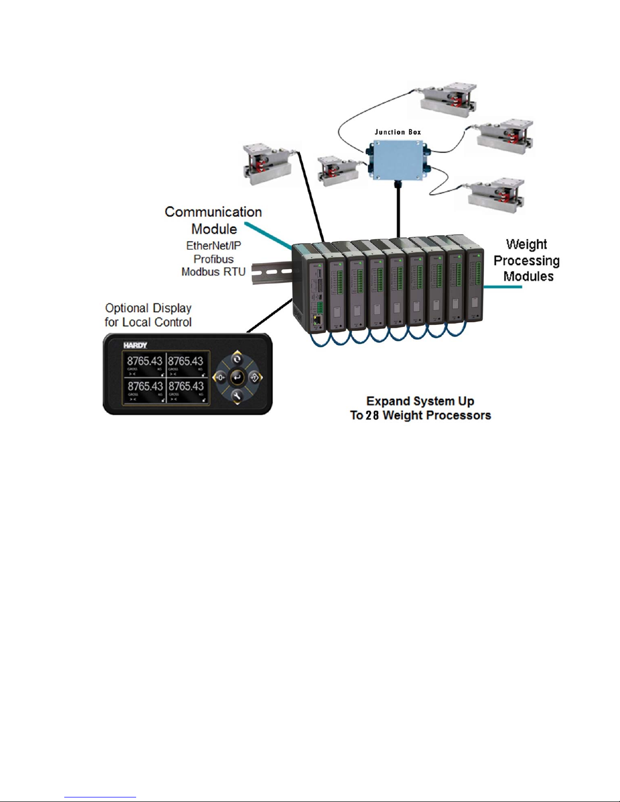
Introduction to the HI 6600 Modular Sensor System
The HI 6600 Modular Sensor System consists of at least one HI 6600 Hardy Gateway Module (HGM) and up
to 28 HI 6610 Weight Processor Modules (WPM). See specific system recommendations in Chapter 2 on
configuring a Modular Sensor System.
The system communicates with PLCs, PACs and DSCs over EtherNet/IP, Modbus-RTU, Profibus-DP and
other popular communication pr ot ocols via a single communication link.
Page | 8
Page 9
HI 6600 Series Modular Sensor System User Guide
Page | 9
The system is used for front end signal processing o f strai n - g age typ e s ensors a n d load c e l ls for all types of
industrial and machine weighing applications.
Sensor System conditions, converts and
load sensors or scales to a variety of control and monitoring systems.
The HardyNet Gateway Module (HGM or HI 6600) offers users many communication choices including
Ethernet TCP/IP, Modbus RTU, Modbus TCP and either EtherNet/IP or Profibus-DP.
The HI 6600 series can be used with or without an optional Hardy HI 6110 display. The display is a bright
4.3” high-contrast LCD capable of high-resolution graphics and help text discrete messaging. The HI 6110
display can be panel mounted near the Gateway Module or remotely up to 100 feet away to provide a user
interface for operating, calibrating or setting-up the system.
The modular array, small enclosures and low power consumption enable high density cabinet design for
systems that require up to 28 channels of processed weight .
Operating blind or with an optional display, the Modular
communicates stable processed weight readings from connected
Page 10

HI 6600 Series Modular Sensor System User Guide
Typical Applications
Ideally suited for applications that require multiple channels of weight, the HI 6600 series serves a variety of
industrial weighing needs found in batching, blending, filling, dispensing, inventory management, level by
weight and check by weight verification.
HI 6600 Series Model Numbers
Model Number
HI 6600-EIP Hardy Gateway Module - EtherNet/IP
HI 6600-PB Hardy Gateway Module - Profibus-DP
HI 6610-WP Weight Processing Module, no display
HI 6110
Description
Optional Display Panel
Page | 10
Page 11

HI 6600 Series Modular Sensor System User Guide
Chapter 2
Specifications and Featur es
• • • • • •
Chapter 2 provides specifications for HI 6600 series instruments. The specifications listed are designed to
assist in the installation, operation and troubleshooting of your instrument. All service personnel should be
familiar with this section before installing or repairing the instrument.
Basic Specifications
HI 6610 Weight Processing Module (WPM)
Number of Channels
Each Weight Processing Module is a single channel of weight. HI 6600 Modular Sensor System can support
up to 28 channels. The actual number of channels that can be transmitted by a single I/O table request depends
on the PLC interface format.
EtherNet/IP: Up to 28 Channels per request
Profibus-DP Up to 10 Channels per request
Modbus-TCP: Up to 14 Channels per request
Modbus-RTU: Up to 14 Channels per request
Note: See section below on Power Requirements for Configuring your Modular Sensor System Over Distance for
specific recommendations on number of channels and maximum system distances.
Update Rate per Weight Processing Module (WPM)
110 times per second per channel (processed weight, display, communications)
Weight Pr oce ssi ng Module (WPM) Resolution
Displayed - 1:10,000
Internal - 1: 8,388,608
WAVERSAVER
User Selectable
OFF, 7.50 Hz, 3.50 Hz, 1.00 Hz (default ) , 0.50 Hz, 0.25 Hz
®
Averages
1 to 250
User-selectable in Single Increments
Page | 11
Page 12

HI 6600 Series Modular Sensor System User Guide
Load Sensor Input per WPM
Up to four 350-ohm full Wheatstone bridge, strain gauge load sensor/cells (5 volt excitation) can be
connected to the weigh scale input on each WPM.
Note: Connecting 2 or more load cells requires a summing card or Junction Box.
Non-linearity
0.0015% of full scale
Common Mode Rejection
110 dB at or below 60 Hz
Common Mode Voltage Range
2.5 VDC maximum (with respect to earth ground)
Load Cell Excitation
5 VDC +/- 1.15 VDC maximum
Isolation from digital section 100 0 VDC m ini mum
C2 Calibration Input
Isolation from digital section 1000 VDC minimum
Load Sensor Cable Lengths per Weight Processing Module
250 feet maximum of C2 authorized cable (Maximum of4 load sensors) with a
or IT Junction box
DC Input Volt age Weight Process ing Module (with 4x 350ohm load cells)
1.72 Watts, 12-27 VDC, 71-118 mA
Maximum System Span Distance
500 feet (150 meters) span from the first Weight Processor Module to the Hardy Gateway
Module
Note: See section below on Power Requirements for Configuring your Modular Sensor System Over Distance for
specific recommendations on number of channels and maximum system distances.
Summing Card
Hardy Gateway Module (HI 6600)
Network Connectivity
Ethernet TCP/IP
Ethernet UDP
Modbus-RTU over RS485
Modbus TCP
EtherNet/IP (EIP models) or Profibus-DP (PB models)
USB Port: For Parameter Saving and Backup to PC
Display Port: For optional Front Panel Display
Scoreboard: Uses RS485 port to stream weight readings to a large display or data logger
Page | 12
Page 13

HI 6600 Series Modular Sensor System User Guide
DC Input Volta ge Hardy Gateway Module (HGM)
3.90 Wat ts, 12-24 VDC, 162-290 mA
Optional HI 6110 Front Panel Display
Monochrome 480 x 272 LCD di splay with back light
Five tactile keys for menu item selection
Displays in either white on black or black on white
IP66 rated when mounted on a smooth, rigid surface (minimum 16-gage) using the supplied gasket
2 watts maximum
Environmental Requirements
Operating Temperature Range
-10ºC to 60º C (14º to 140º F)
Temperature Coefficient
Less than 0.005% of full scale per degree C for Cal-LO and Cal-HI reference points
Storage Temperature Range
-40 to 85º C (-40º to 185º F)
Humidity Range
0-90% (non-condensing)
Environmental
Intended for Building-in, indoor use only at ambient temperatures between 10ºC to 60º C (14º to 140º
F) with a pollution degree of 2.
Approvals
UL, CUL and CE
Network Certifications
EtherNet/IP ODVA Conformance Tested, Level 3
Profibus-DP by Profibus.org
Features and Capabilities
Hardy Process Toolbox
The Hardy Process Toolbox is a set of productivity tools that support process weighing functions. Each tool in
the Hardy Process Toolbox saves time, increases accuracy, improves efficiency or reduces risk in process
weighing applications. The HI 6600 includes the Toolbox functions discussed below.
C2® Calibration
Traditional calibration uses certified test weights. C2® Electronic Calibration allows a scale to be calibrated
without the need for test weights. A C2 weighing system consists of up to four load cell sensors per WPM, a
junction box, interconnect cable, and an instrument with C2 capabilities (e.g., the HI 6600 series instrument).
Each Hardy Process Solutions C2-certified load sensor outputs digital information used for calculating the
Page | 13
Page 14

HI 6600 Series Modular Sensor System User Guide
calibration. When the HI 6600 series instrument reads the signals from the load sensors, it calibrates the scale
based on the load sensor’s output plus a user-supplied reference point value (from 0 to any known weight on
the scale).
INTEGRATED TECHNICIAN
In conjunction with an IT junction box, the HI 660 0 seri es feat ures I NTEGRATED TECHNICIAN® (IT), a
system diagnostics program that makes it possible to diagnose weighing system problems from Hardy’s Web
Server or a connected optional display panel. IT reads individual load sensor voltages and weights and isolates
individual system components for quick and easy troubleshooting
NOTE:
load cells on the system.
WAVERSAVER
When measuring small weight changes, the effects of m echanical vibration and noise from feeders and other
plant environmental conditions can introduce substantial interference. WAVERSAVER factors out vibration,
noise, and other interference-related signals from the load cell so the weight processor can better decipher the
actual weight data.
While WAVERSAVER can factor out noise with frequencies as low as 0.25 Hz, five cut-off frequencies can
be selected, with higher frequencies providing a faster response time. The default factory setting is 1.00 Hz
vibration frequency immunity.
If you do not have a Hardy IT Junction Box connected to the HI 6600, the weight reading is the total for all
®
®
C2, INTEGRATED TECHNICIAN and WAVERSAVER are registered trademarks of Hardy Process
Solutions.
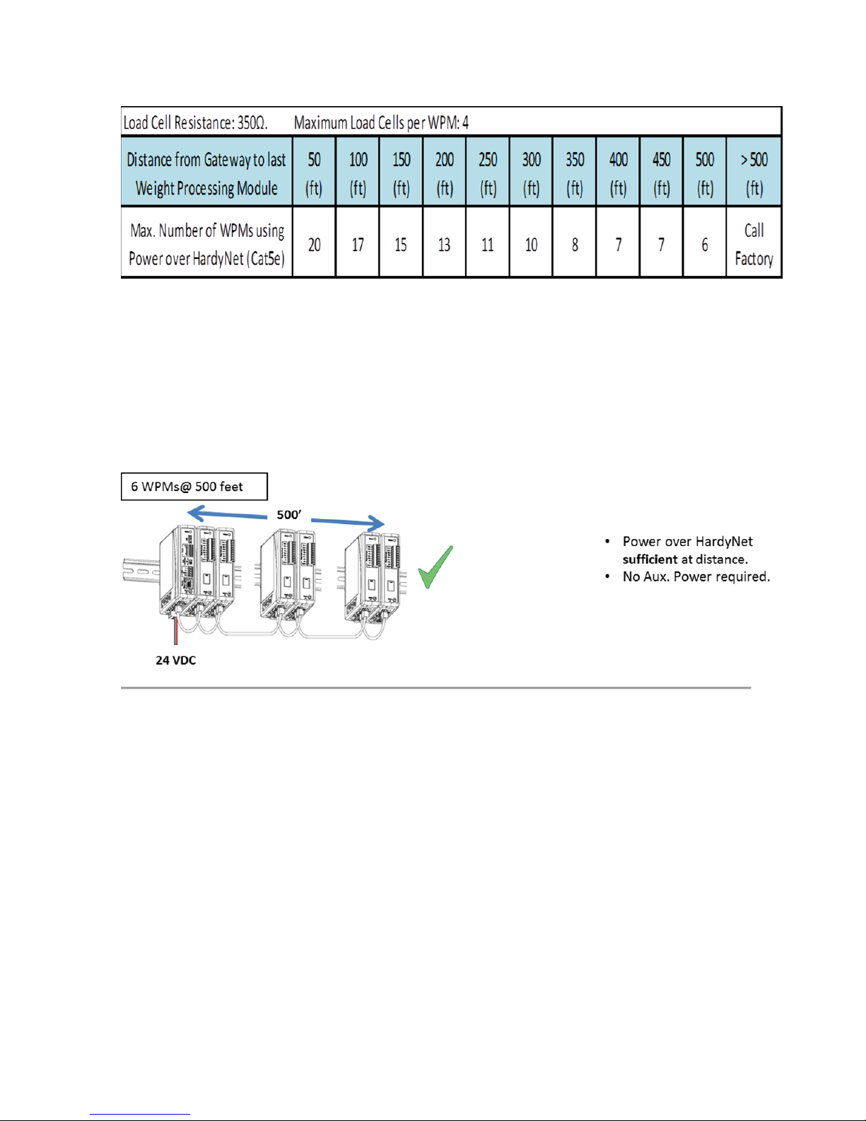
Power Requirements for Configuring Your Modular Sensor
System over Distance
Distributing power over Cat5e cabling to a fully loaded HI 6600 system (up to 28WPM units, up to 28 junction
boxes and up to 120 350 Ohm load cells) is beyond the current carrying ability of Cat5e cable.
Deploying a fully loaded system up to 500 feet poses no harm to the instrumentation or sensors. However, the
current required can prevent the system from discovering modules that do not have enough voltage available or
trip an over-current protection circuit until the condition is cleared.
Weight Processing Modules may require auxiliary power for systems consisting of a large number of channels
at large distances or that use non-Hardy load cells that have varied input resistances.
Below is table 1 showing the maximum number of units of specific distances running over Cat5e without any
additional power.
Page | 14
Page 15
HI 6600 Series Modular Sensor System User Guide
Table 1: Maximum number of WPM Units at specific distances without Auxiliary Power
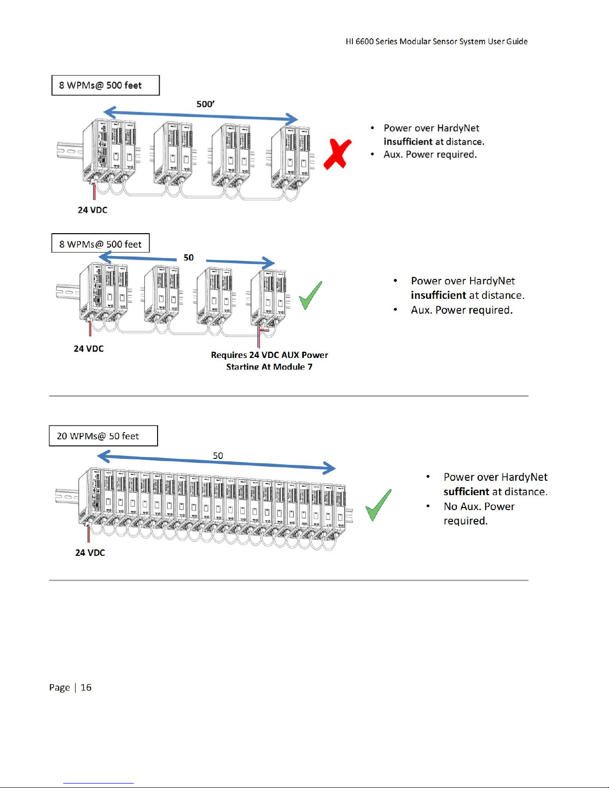
To add either distance or the maximum number of units, you will need to apply auxiliary power as shown in
the following configuration scenarios.
Page | 15
Page 16
HI 6600 Series Modular Sensor System User Guide
Page | 16
Page 17
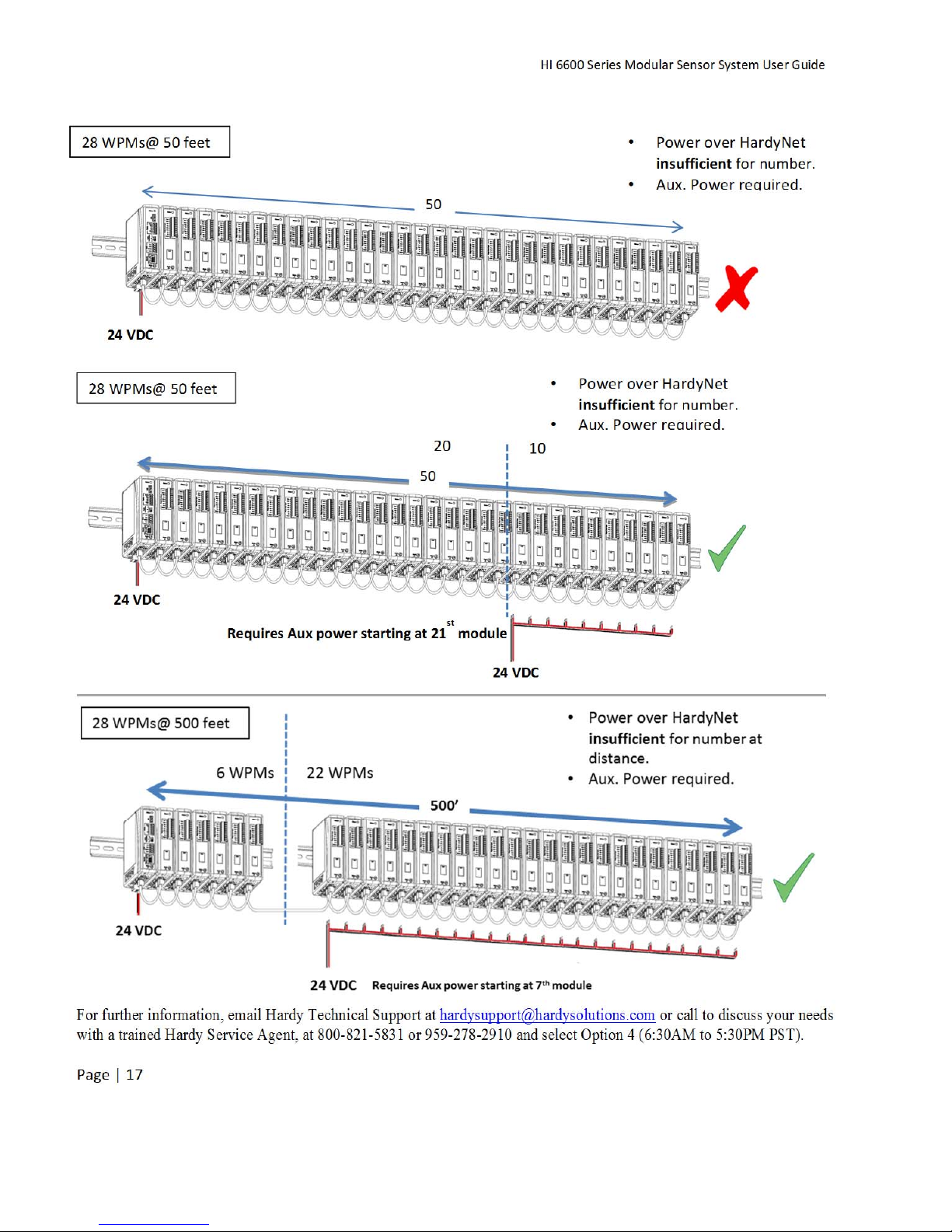
HI 6600 Series Modular Sensor System User Guide
For further information, email Hardy Technical Support at hardysupport@hardysolutions.com or call to discuss your needs
with a trained Hardy Service Agent, at 800-821-5831 or 959-278-2910 and select Option 4 (6:30AM to 5:30PM PST).
Page | 17
Page 18

HI 6600 Series Modular Sensor System User Guide
Chapter 3
HI 6600 Hardware Installation
• • • • • •
Chapter 3 covers physical installation of HI 6600 Modular Sensor System. User and service personnel should
read this chapter before installing or operating the HI 6600 Modular Sensor System.
Safety
Before you begin installing your HI 6600 series equipment, please review the important safety
precautions below.
Do not operate or work on this equipment unless you have read and understand the instructions and warnings
in this Manual. Failure to follow the instructions or heed the warnings could result in injury or death. Hardy
Process Solutions provides manuals in PDF format that are easily downloaded from our website, free of
charge. Look under the Docs & Programs tab on the web pa ge fo r each product.
General Precautions
Always disconnect the power cord before disassembling.
Always replace broken or damaged module s or har dw are i mmediately.
Always check to be sure that no loose parts are sitting on printed circuit boards or electrical
connectors or wires when disassembling or reassembling.
Always protect printed circuit boards from electrostatic discharge (ESD). Always use approved ESD
wrist straps and anti-static pads.
Unpacking
1) Before signing the packing slip, inspect the packaging for damage, and report damage of any kind to the
Page | 18
WARNING - EXPLOSION HAZARD - SUBSTITUTION OF COMPONENTS MAY
IMPAIR SUITABILITY FOR DIVISION 2.
A VERTISSEMENT – Risque d’explosion – La substitution de composants peut
diminuer la conformité pour la Division 2
WARNING - EXPLOSION HAZARD - DO NOT DISCONNECT EQUIPMENT
UNLESS POWER HAS BEEN SWITCHED OFF OR THE AREA IS KNOWN TO BE
NON-HAZARDOUS
A V ER TISSEME NT – Risque d’explosion – Ne p as débrancher l’équipement à
moins que l’alimen tation soit cou pée ou que la zone ne présente p as de risques
carrier company.
Page 19

HI 6600 Series Modular Sensor System User Guide
2) Check to see that everything in the package matches the bill of lading.
3) If items are missing or you have any questions, contact Customer Service at:
Hardy Process Solutions
9440 Carroll Park Drive San Diego, CA 92121
Phone: (800) 821-5831
International: (858) 292-2710
FAX
:
(858) 278-6700
Web Site:
E-Mail:
Record the model number and serial number of the HI 6600 series instrument. Store them in a conven ient,
secure location for reference when contacting Hardy Customer Service Department or to buy parts or firmware
upgrades.
http//www.hardysolutions.com
hardysupport@hardysolutions.com
Tool List
To install the HI 6600 series the following tools will be required.
Jewelers screw driver (to make and modify cable assemblies)
10-50 mm Unibit (for optional display installation)
Drill with 5mm drill bit (for optional display installation)
8 mm nut wrench or socket (for Optional Display)
Installing the HI 6610 Modules
Before getting started, take the following precautions:
WARNING - Electrostatic discharge may damage semiconductor components in
the module. DO NOT TOUCH THE CONNECTOR PINS.
AVERTISSEMENT – Les décharges électrostatiques peuvent endommager les
composants semi-conducteurs dans le module. NE TOUCHEZ PAS les broches du
connecteur.
Wear an approved wrist-strap grounding device when handling the instrument.
Touch a grounded object or surface to rid yourself of any electrostatic discharged prior to
handling the instrument.
Handle the instrument from the bezel in front away from the connector. Do not touch the
connector pins.
Do not install the instrument right next to an AC power source or high voltage DC equipment
Route all the low voltage cables away from high voltage cables
Page | 19
Page 20
HI 6600 Series Modular Sensor System User Guide
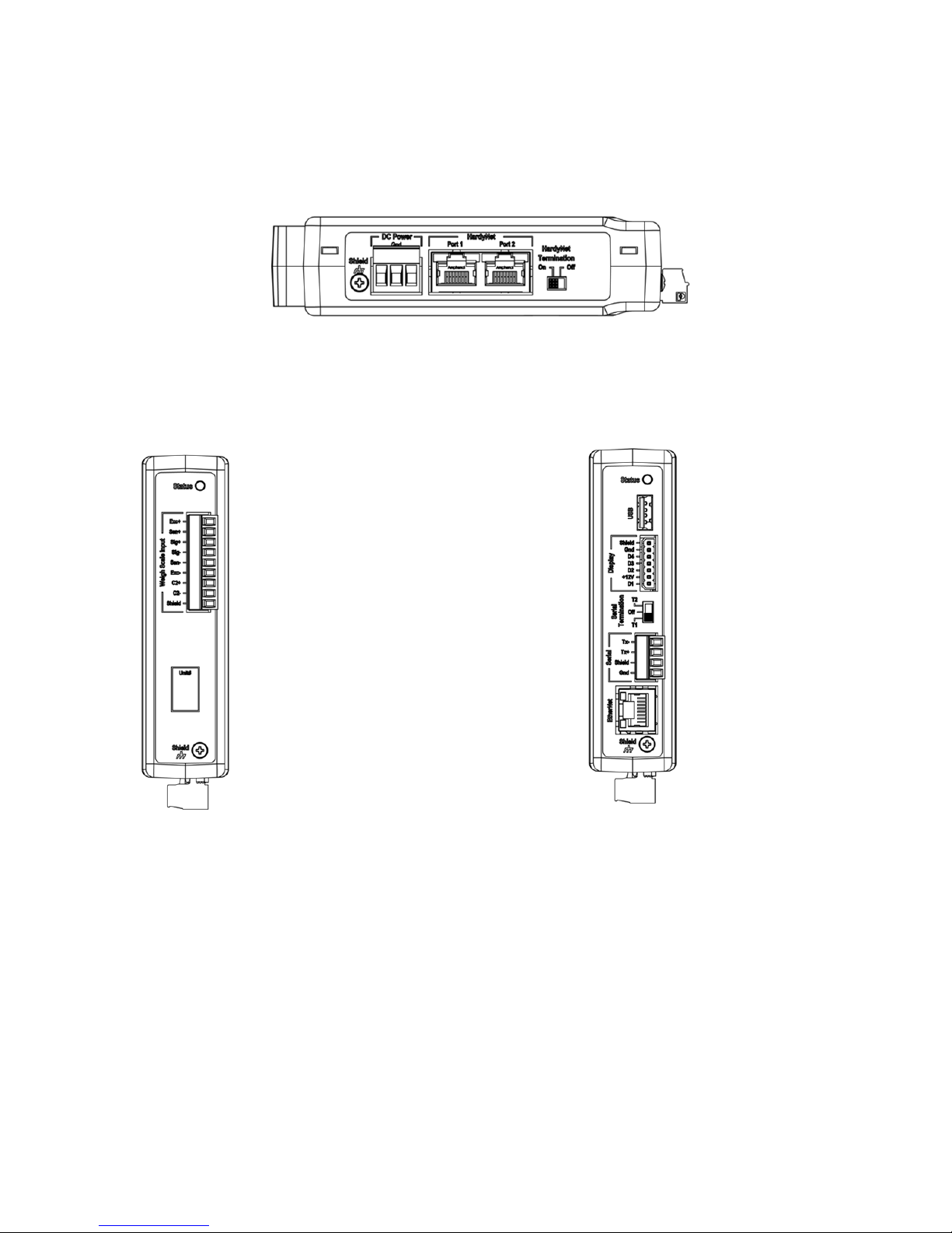
Overview of the HI 6600 Hardware
Before installing the HI 6600 Series, familiarize yourself with the basic configuration as shown below.
DC Power, Shield, Ports for HardyNet and a Termination switch can be found on the bottom of both the Hardy
Gateway Module and the Weight Processing Modules.
The RJ45 ports located on the bottom are used to connect the system using Cat5e cabling. Communications
between modules (HardyNet) as well as power distributed from the Gateway Module to the Weight Processing
Modules is carried on the Cat5e cabling.
Weight Processing Module Hardy Gateway Module
The Weigh Scale Input is located on the front of the HI 6610 Weight Processing Module.
Located on the front of the HI 6600 Gateway module is a USB port (used to store system settings), a Display
port (for connecting to an optional HI 6110 display), Serial Termination switch, Serial Port and an Ethernet
Port.
Page | 20
Page 21
HI 6600 Series Modular Sensor System User Guide
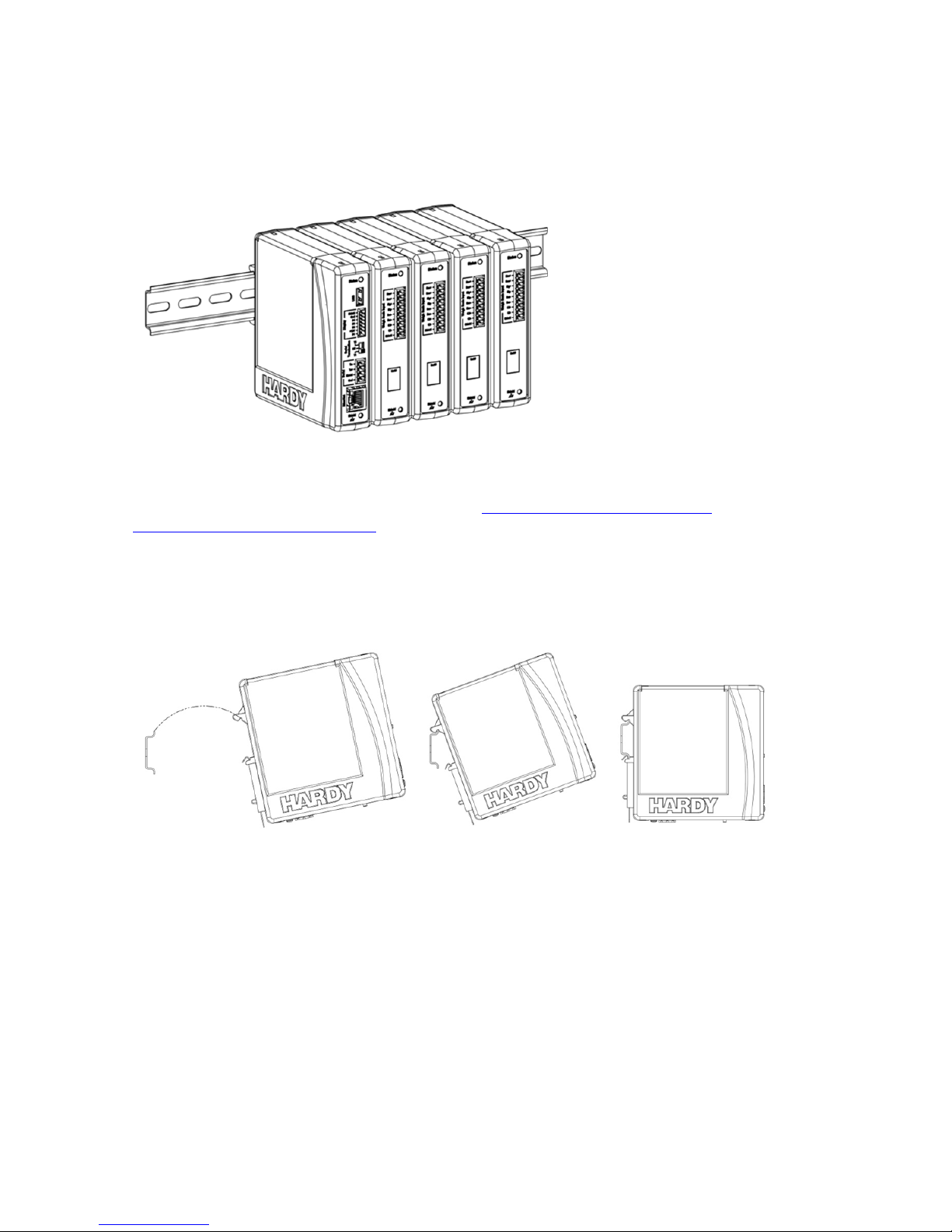
Installation
The HI 6600 Series WPMs and HGMs are designed to be installed on a DIN rail as shown below.
The MAXIMUM span between the first and last module that comprise a system is 500 feet (150
meters). See Chapter 2 for specific recommendations on Power Requirements for Configuring
Modular Sensor Systems Over Distance.
Note: Use DIN rail conforming to EN 60715 and EN 50022.
Begin by installing the WPMs or HGMs onto the DIN rail as shown below.
1) Hook DIN rail bracket onto the DIN rail using the groove at the top of the bracket
2) Rotate the instrument down until the spring-clip comes in contact with the DIN rail, then press
firmly on the bottom on the instrument until it snaps in place.
3) While holding the front of HI 6600 series module, gently pull away from the DIN rail to verify
that it is mounted correctly.
Page | 21
Page 22

HI 6600 Series Modular Sensor System User Guide
To remove:
1) Disconnect all wiring on the underside of the modu le to expose the spring-clip slot.
Spring Clip Slot
2) Insert a flat-blade screw driver into spring-clip slot then gently lift up on the screwdriver handle, using
the back corner of the module to assist in prying the spring-clip in a downward direction.
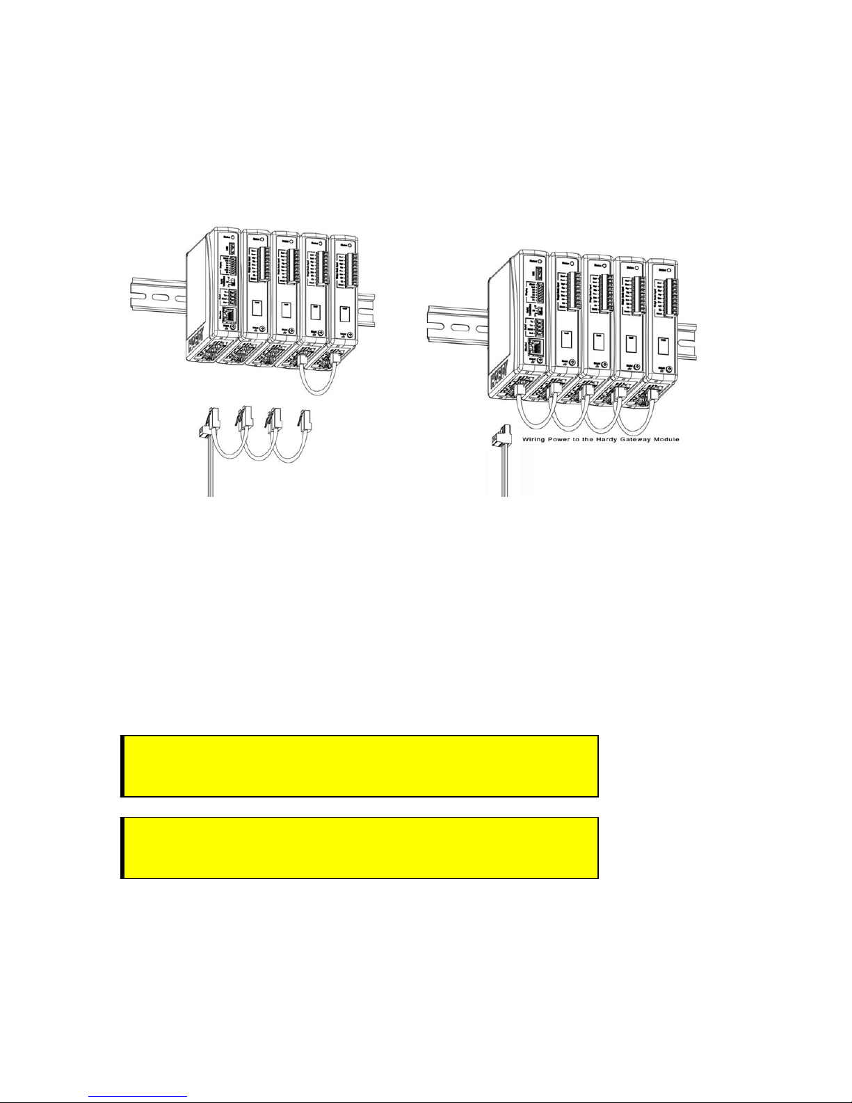
Cabling the Units Together
Once the units are all placed on a DIN rail, connect them together in a series using the RJ45 ports on the
bottom of the units and Cat5e cable.
The Cat5e cabling carries communications between the modules and distributes power from the Hardy
Gateway Module to the Weigh Processing Modules.
Page | 22
3) Once the spring-clip is disengaged from the DIN rail, the module will easily lift off the DIN rail.
Page 23
HI 6600 Series Modular Sensor System User Guide
Redundant DC power may also be supplied individually to each Weight Processing Module via the DC power
input terminal located on the bottom of the module. DC power supplied to individual Weight Processing
Modules is isolated and not distributed to other modules on the system.
At minimum, DC power must be supplied to the Gateway Module.
The maximum distance between the first and last module on a system is 500 feet (150 meters). The HardyNet
termination switch should be turned on for the first and last units in the series. In most cases, this is the HI
6600 Gateway module and the last HI 6610 Weight Processing Module on the network. All other HI 6610-WP
modules between the Gateway Module and the last weight processing module should have the termination
switches turned off.
NOTES: DO NOT USE CROSS-OVER CABLES.
Port Numbers have no effect on cabling (i.e. connecting either Port 1 to Port 2 or Port 2 to Port
1) is acceptable.
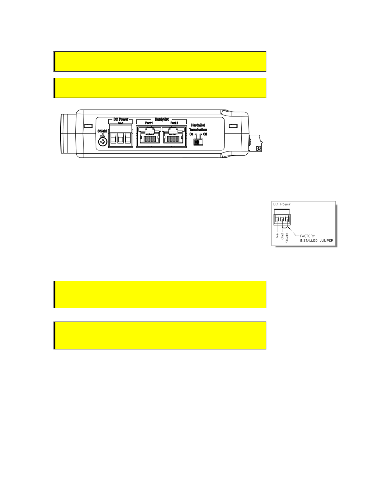
DC Power Input
WARNING - Do not operate with incorrect line voltage. To do so will result in
property damage and/or personal injury. Make sure that the power source does
not exceed 24 VDC.
A VER TISSE MENT – Assurez-vous que la source d’alimentation ne dépass e pas
24 V. L’utilisation d’un mauvaise voltage peut résulter en dégâts matériels
et/ou des risques de blessures.
Page | 23
Page 24
HI 6600 Series Modular Sensor System User Guide
WARNING - Be careful not to reverse the ground and hot wires, which can
result in damage to the equipment.
A V ERTI SSEMENT – Attention à ne pas inverser le sol et fils chauds, ce qui peut
entraîner des dommages à l'équipement.
A power-limited 12-24 VDC power supply (Class 2) must be used on the DC input wiring.
DC power should be supplied by a clean primary line, directly from the DC power source.
1) Make sure the VDC power is shut off before installing the wires to the
connector.
2) Connect the 24 VDC voltage wire, ground wire and shield wire to the
connector that
jumper connects the Earth
them common, and should remain in place.
plugs into the DC voltage header at the rear panel. The
ground and the internal ground making
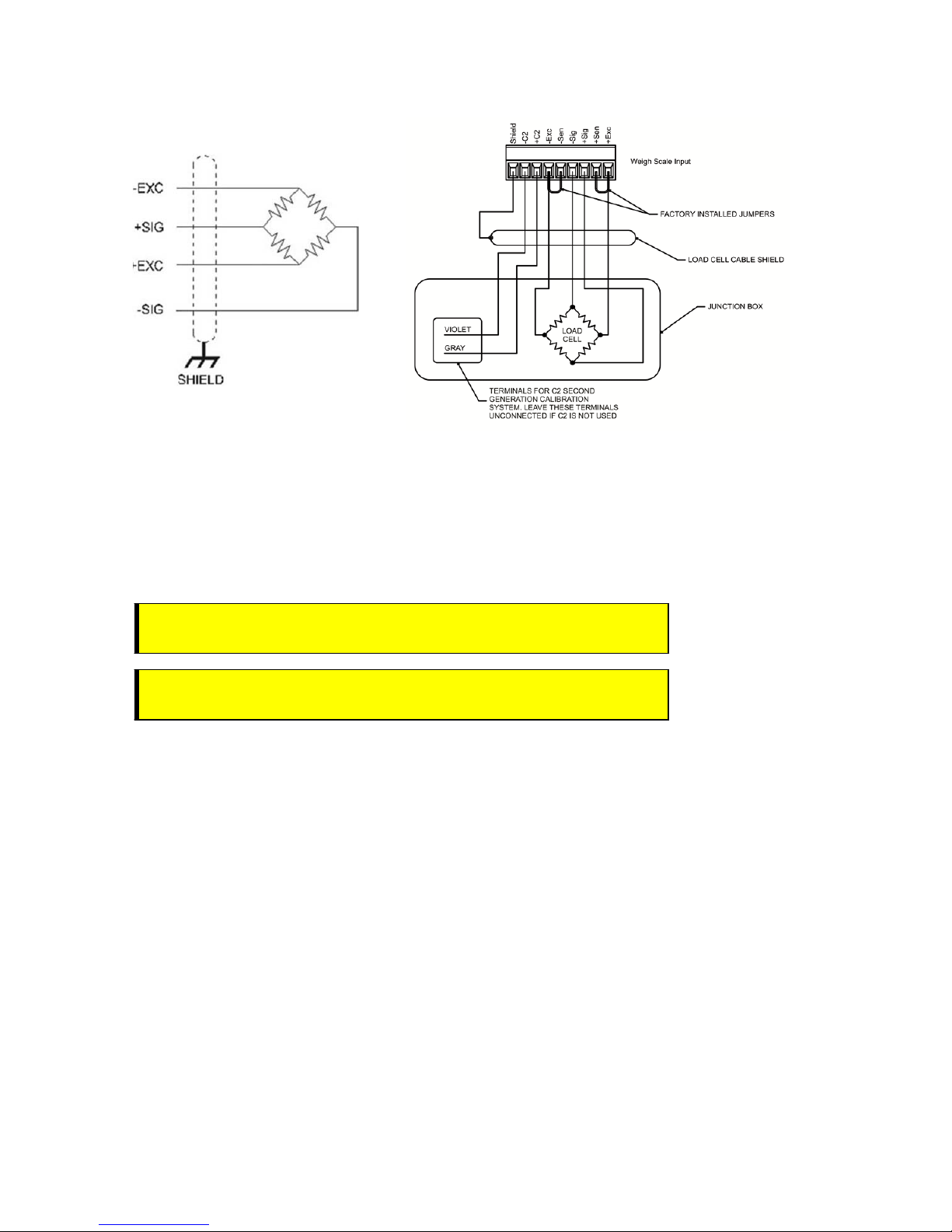
Connecting Sensors
The diagrams below show Hardy Load Sensors with C2 and non-Hardy Load Cells (4 wire and 6 wire are
similar except 6 wire adds sense wiring) that do not have C2. Wire the terminal connector that plugs into the
front of the Weight Processor Modules by carefully following the Weigh Scale Input termination label.
Page | 24
3) Plug the connector into the bottom panel.
4) Apply VDC power to the unit .
WARNING - If the HI 6600 series equipment is used in a manner that is not
specified by the manufacturer, th e pro t ecti on provided by the equip men t may
be impaired.
A V ERTI SSEMENT – Si l'équipement de série HI 6600 est utilisé d'une façon qui
n'est pas spécifiée par le fabricant, la protection fournie par l'équipement peut
être altérée.
Page 25
HI 6600 Series Modular Sensor System User Guide
Non-C2 load cell wiring Hardy load sensor with C2
Note: when connecting the HI 6600 series instrument to a
be connected between the +Sen and –Sen
See the I/I Diagram for further detail. You can find the I/I Diagram in the Hardy website
under Products>Weight Processors>HI 6600 Modular Sensor System and then select the
Docs & Programs tab to download the I/I Diagram.
WARNING - Instrument power should be routed away from all ot her signal
cables to avoid electrical interference.
AVERT ISSEM ENT – Tens ion de l'appareil doivent être acheminés à l'écart de
tous les autres câbles de signau x pour éviter toute interfé rence électrique.
connections for the ju nction box a nd the instru ment.
junction box, the sense lines woul d
Installing the Optional Display
The following section provides details on how to mount the Optional Front Panel Display and connect to the
HI 6600 HGM.
Blind Unit (No display)
The front display is not necessary for the HI 6600 series instrument to operate as a weight processor. Blind
units can be fully configured using the Web b ro wser c om munication.
Optional Remote Display Mount
The HI 6600 Modular Sensor System is compatible with HI 6110 displays.
Page | 25
Page 26
HI 6600 Series Modular Sensor System User Guide
The optional display for the HI 6600 series instrument can be mounted in a remote location up to 250 feet
(75 meters) from the Hardy Gateway Module by modifying the supplied cable.
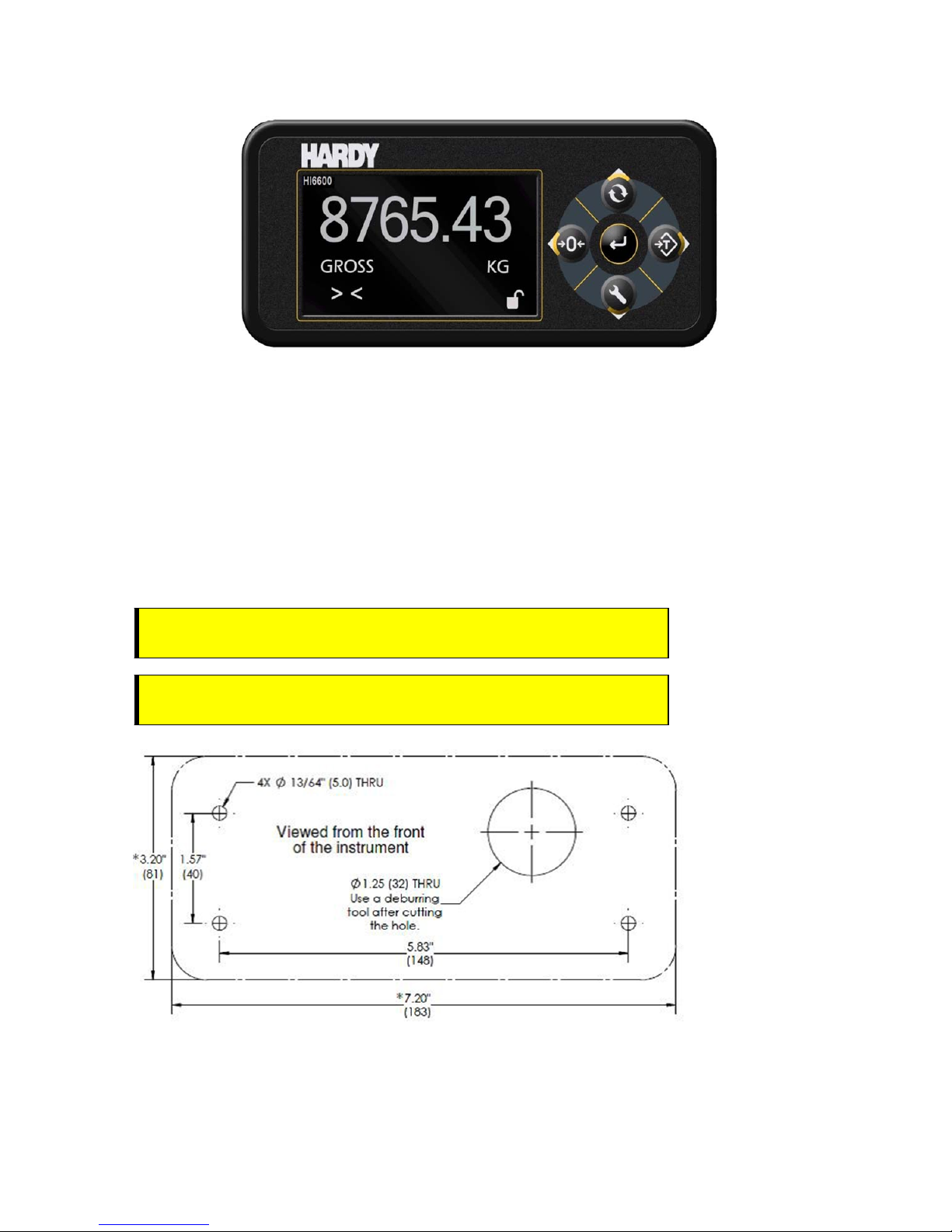
Mounting the Optional Front Panel Display
(1) Make sure that all Electrostatic Discharge (ESD) precautions are taken before and during installation.
(2) A thin plastic template comes with the product. Make the hole pattern in the panel door or cover using
the dimensions provided on the diagrams below.
WARNING - We recommend installing the HI 6600 series modules in a
NEMA 4, 4X or IP 55 rated enclosure or better.
AVERTISSEMENT – Nous vous recommandons d'installer le HI 6600 dans
un boîtier NEMA 4, 4X ou IP 55 ou mieux.
Panel Hole Dimensions (not displayed to scale)
Page | 26
Page 27
HI 6600 Series Modular Sensor System User Guide
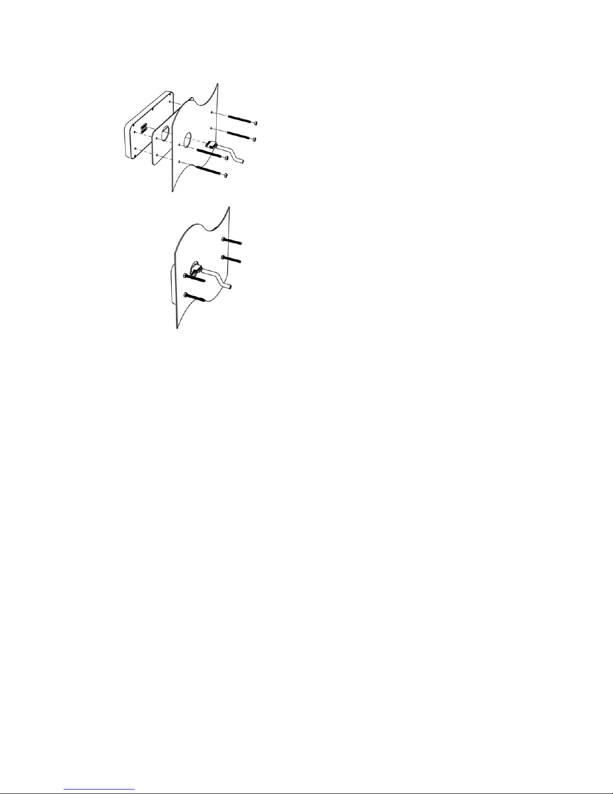
i) Connect and hand-tighten the four screw rods into the Optional Front Panel display.
ii) Place the gasket over the screw rods then slide the screw rods through the panel until flush with the
surface.
iii) Place washer and nut onto the screw rods sticking through the panel. Tighten nuts so that the gasket is
fully compressed and that the metal bezel of the display is in contact with the panel. Nuts should be
torqued to 20 inch-lbs to ensure the seal required for an IP-66 rating.
iv) Remove the terminal connectors from the cable assembly provided and replace the original cable with the
desired cable length. See instructions above for Making Longer Display Interface Cables below.
v) Connect the display cable to the back of the display and to the Display Port located on the front of the
Hardy Gateway Module
Page | 27
Page 28
HI 6600 Series Modular Sensor System User Guide
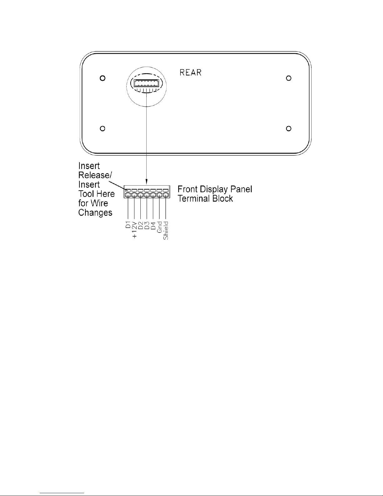
Making Longer Display Interface Cables
The terminal block uses a spring cage type contact. There is a slot provided to use an insert/release tool. The
tool is a 2.0 mm x 0.4 mm wide flat blade screw driver. Inserting the end of the small screwdriver tool opens
the cage contact and allows one wire to be inserted. Removing the insertion tool with b are co nductor wire
inserted will lock the connection.
Wiring Specifications
Wire si ze: 20 AVG maximum / 26 AVG minimum
Maximum cable length: 100 ft. (30.48 meters)
Use three twisted pairs with a drain wires
Pair wires +12 and GND, D1 and D2, D3, and D4
Page | 28
Page 29
Chapter 4
HI 6600 Series Modular Sensor System User Guide
Instrument Configuration
• • • • • •
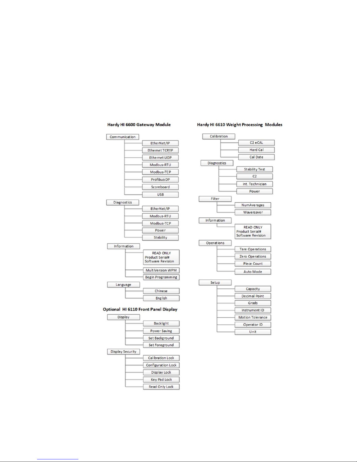
Menu Structure
The menu tree below shows the location of commands and parameters used to configure and use the system.
Page | 29
Page 30

HI 6600 Series Modular Sensor System User Guide
The system can be set-up, calibrated and operated either through the built-in Webserver or through an optional front panel
display. The menu structure above may be followed using either interface.
Using the Webserver
To use the Webserver, a connection must first be established between the Hardy Gateway Module and a connect PC. The
following steps will assist in establishing a connection:
1) Connect an Ethernet cable between the RJ45 port located on the front of the HI 6600 Gateway Module’s RJ45
and a PC then power up the instrument. A cross-over cable is not required, but can be used.
2) The instrument will auto-negotiate settings suitable for a variety of operating systems and network
configurations. Wait approximately 15 seconds and check to see if the green light of the Ethernet port is on and
blinking – if so, skip to step 8 – you are connected.
3) If the green light on the Ethernet port does not light up, use the Optional Display to check that the unit’s Enable
DHCP is turned off and follow steps 4 through 8 If an optional display is not available, please call Hardy Tech
Support for further assistance.
4) Using the unit’s Fixed IP address (the default is 192.168.000.100), the PC must now be assigned a unique IP
address (for example, 192.168.000.101)
There are two simple rules for the IP Address:
•
It must have the same network identifier as the computer.
•
It must have a different node identifier than the computer.
5) On a PC running windows, open Internet Properties (TCP/IP).
Click in the ‘Use the Following IP Address’ checkbox; then enter the following into the TCP/IP Properties
dialog.
•
IP Address = 192.168.0.101
•
Subnet Mask = 255.255.255.000
6) Select OK on the TCP/IP Properties dialog box. The computer is now configured.
7) Enter the HI 6600 HGM’s IP address into the Windows PC Web browser to access the embedded web browser.
For example: http://192.168.000.100
NOTE
Additional information for setting up communications between the Gateway Module and the PLC,
DCS, or PC is under Network Communications (Chapter 6).
Page | 30
Page 31

HI 6600 Series Modular Sensor System User Guide
Once connected, browse the webpages by following the menu tree presented in the beginning of this chapter. Changes are
made by clicking the item and either selecting an option or inputting a value using your PCs keyboard.
NOTE: Selections and inputs are ONLY saved to memory by clicking SAVE PARAMETERS in the webpage.
Usin g the HI 6110 Front Panel Display
1) Toggle between showing multiple channels and a single-channel by pressing the ENTER button
2) Move the quadrant outline to the desired channel by using the arrows keys. Press ENTER to select the
channel, once a channel is selected it will show in full-display mode and ch ange function of the buttons
from navigation (up, down, left, right) to instrument function (mode, config, zero, tare).
Instrument 1 Instrument 2
Instrument 3 Instrument 4
Instrument 3 Instrument 4
Scroll through available instruments by pressing the UP and DOWN arrows.
1) Enter Set-Up for the selected channel by pressing the CONFIG button.
Pressing the CONFIG button min imizes the d isplayed weight valu e and shows a list o f submenus to the left
that follow the menu tree presented in the beginning of this chapter.
Page | 31
Instrument 5 Instrument 6
Page 32

HI 6600 Series Modular Sensor System User Guide
2) Navigate UP and DOWN the submenus using the arrow keys, then select a menu by pressing the ENTER
button.
3) Fixed options with in a submenu are selected by using th e UP & DOWN buttons to navigate to the choice,
then by pressing ENTER key to select. Once an option is selected, back out of the submenu by pressing the
LEFT arrow key.
4) Entering Numeric and Alphanumeric values are done pressing the UP & DOWN b uttons to change a value
and RIGHT & LEFT buttons to move the position of the cursor. Once a value is keyed in, press the ENTER
key to save then the LEFT arrow key to return to main menus.
5) Values are saved to memory only by backing out to the top level.
Mode Button
Press the Mode Button to switch between differe nt weighing modes of:
Page | 32
•
GROSS: Displays the GROSS weight of the system.
NET: Displays the NET weight of the system. The NET weight displayed is the
TARE value.
COUNT: Counts the number of objects once the weight for one object is set.
GROSS weight minus the
Page 33

HI 6600 Series Modular Sensor System User Guide
The displayed mode on the instrument can also be changed by selecting DISPLAY MODE on the Operations webpage
and choosing Gross, Net or Count from the drop-down menu or by sending the DISPLA Y MODE command over
communications.
Channel Identification
System Discovery
Once the HI 6600 Series Modular Sensor System is physically installed, connected and powered, a discovery process is
required to allow the Hardy Gateway Module to identify other modules connected to the system. HardyNet is the
communication protocol that serves as a backplane to the system; distributing data, control and power to between
modules.
This discovery process can be initiated in a number of ways and should be used each time the overall system is changed;
for example removing a module from the system or adding a new module to the system.
The discovery process enables the Gateway Module to identify and track changes of other modules present on HardyNet.
The discovery process is initiated manually by selecting START DISCOVERY under the HardyNet sub-menu of the HI
6600 Gateway Module.
Discovered Modules are added to a list that is saved in non-volatile memory of the Gateway Module. The discovery
process is designed to only add units that are not already saved in memory. If a Module has been physically removed or
disconnected from the system, it must be manually deleted from the list of available modules by selecting DELETE
CHANNEL. A module that is accidentally deleted can be discovered again by usi ng the START DISCOVERY function.
WARNING - Modifying channels by using the SWAP, DELETE, or REPLACE functions will alter
data written to the I/O table and could affect the system operation and functionality. Use of
HardyNet Security is advised to prevent unauthorized or accidental modifications to the system
set-up.
HardyNet Security must be UNLOCKED in order to make modifications to a system. The default HardyNet Security
password is 1111.
The number of Modules discovered (ie: channels of weight) connected to the system will be displayed as Discovered
units: XX on the Web Browser as shown below or listed in the Discovery section of the optional front panel display once
the process is complete. The total number of discovered units includes both modules saved in memory and any additional
modules added to the system.
NOTE: Use of the Webserver (shown below) is recommended for initial system set-up and changes to a system
NOTE: The new module will appear at the end of the channel list. If need be, reassign the channel
Page | 33
AVERTISSEMENT – Modifier les canaux en utilisant le SWAP , supprimer ou remplacer les
fonctions modifieront les données écrites sur la table I / O et pourrait affecter le fonctionnement
et la fonctionnalité du système . L'utilisation de HardyNet sécurité est conseillé de prévenir les
modifications non autorisées ou accidentel au système mis en place
with a large number of channels.
number and change its order in the list by using the Swap Channel process described above.
Page 34

HI 6600 Series Modular Sensor System User Guide
Instrument ID
Use the Instrument ID to assign the Gateway Module with a meaningful name (such as Batching System A). Use of
Instrument ID is especially useful if more than one HI 6600 system is present on a network. Select SAVE
PARAMETERS write the Instrument ID into non-volatile memory.
Channel Identification
During the discovery process, new channels on the system are identified and sequenced in order of discovery, not by
physical location or distance from the Gateway module; use the Channel Identify function to easily locate a module,
assign an identification name or number, change its sequence order or delete it from the system. The module’s indicator
light will blink green once per second when IDENTIFY ON is pressed (Webserver) or highlighted (Front Panel Display).
Naming the Weight Processing Modules
To ease identification of specific Weight Processor Modules on the system, a meaningful name (ie: Ingredient
A, BIN 5 or Vessel #28) may be assigned to the module by using CHANNEL ID. Select the channel to assign
a new Channel ID and click CHANGE CHANNEL, input up to a 15 character alpha-numeric identifier than
click SAVE PARAMETERS to write the new channel name to non-volatile memory.
Page | 34
Page 35

HI 6600 Series Modular Sensor System User Guide
Ordering the Weight Processing Modules
The order in which the channels appear in the drop down menus or on the optional front panel display may be changed by
using the SWAP CHANNEL function in the web server or by selecting the channel in front panel display, pressing enter
to ‘capture’ the channel, moving it by using the UP/DOWN arrows, then pressing enter again to ‘release’ the channel to
its new position.
The SWAP CHANNEL function is useful when there is a desire to match the displayed channel sequence to the actual
physical location of the modules on the system (ie: CH1 nearest to the Gateway Module, CH30 furthest from the
Gateway).
WARNING - Modifying channels by using the SWAP function alters the assigned channel number
and where its data is written the I/O table.
AVERTISSEMENT – Modification des canaux en utilisant la fonction SWAP modifie le numéro
de canal attribué et où ses données sont écrites de la table I / O .
Deleting Channels
Use the DELETE function to remove an unwanted module from the system or unwanted channel information that was
previously saved in the memory of the Gateway Module. This function is often used when replacing a damaged module
with a new module or when deleting the presence a spare module from the drop-down menus during normal operation.
WARNING - Modifying channels by using the DELETE function alters the assigned channel
number and where its data is written the I/O table.
AVERTISSEMENT – Modification des canaux en utilisant la fonction DELETE modifie le numéro
de canal attribué et où ses données sont écrites de la table I / O .
Note: Remove the deleted Weight Processor Module by disconnecting the RJ45 connectors
and using a screwdriver to disengage the spring-clip as shown in Chapter 3.
Replace Channel
In the event of a damaged module, the REPLACE CHANNEL function can be used to easily transfer settings from a
damaged module to a new module placed on the system.
Use the following sequence:
1) Power off system
2) Remove damaged module
3) Connect replacement module
4) Power on system
5) Select REPLACE CHANNEL
The replace channel function initiates discovery and automatically transfers settings from the removed (missing) module
to any new module placed on the system.
Page | 35
Page 36

HI 6600 Series Modular Sensor System User Guide
WARNING - Only one channel can be replaced at a time. If more than one channel needs to be
replaced, repeat the above sequence. The function will fail if more than one channel is removed at
a time or more than one channel is discovered.
AVERTISSEMENT – Un seul canal peut être remplacé par un. Si plus d'un canal doit être
remplacé , répéter la séquence ci-dessus. La fonction échouera si plus d'un canal est supprimé à la
fois ou plus d'un canal est découvert
Saving and Restoring Configuration Data Using the USB port
The HI 6600 Gateway Module provides a USB port to save parameters to a memory stick. Parameters can be saved,
restored, copied and modified from one instrument or channe l to another instrument or channel using this feature.
Details of use can be found in the USB Memory Stick section of the Network Communications section of this
manual.
Suggested Minimum Steps When Setting Up the Instrument For the First Time
Choose a specific Weight Processor Module to set up by selecting a channel either from the front panel display
or on the webserver.
Channel
1) Choose channel to set-up
SET UP (minimum)
1) Select Unit of Measure
2) Input Total Scale Capacity
3) Select Graduation Size
4) Select Decimal Point Position
5) Input Motion Tolerance
Filter
1) Num Averages
2) Waversaver
Page | 36
Page 37

HI 6600 Series Modular Sensor System User Guide
Calibration
1) Cal Date
2) Cal Method
a. C2 eCal
b. Hard Cal
3) Complete Cal Procedure
Setup Parameter Menus
The Setup Menus consists of the following parameters:
Capacity
Decimal Point
Grads
Instrument ID
Motion Tolerance
Operator ID
Unit
Capacity Parameter
Scale Capacity is the scale's nominal operating capacity (the total weight capacity of the scale system). If this value is
exceeded by six graduations, dashes appear on the front display. Communications to and from optional devices are not
affected.
If a Capacity value is entered which conflicts with either the decimal point value or the graduation value, the decimal
point and/or graduation values are automatically modified to match the programmed capacity. It is therefore
recommended that the Capacity parameter is entered first before setting the Decimal Point and Grad parameters.
RANGE: .000001 - 999999 (Default 999999).
On the Web page Or Using the Front Panel Display: enter the capacity in the text box provided or enter the capacity
using the arrow keys.
Decimal Point Parameter
Use the Decimal Point Parameter to set the resolution you want for the WPM.Here you set the location of the decimal point for
the weight resolution. The higher the number, the
scale. Note
RANGE: 0-5 (default 2) Not to exceed 1 part in 100,000
On the Web page Or Using the Front Panel Display: from the Decimal Point pull-down list, select the decimal position for
this instrument or select from the list of decimal point values supported using the arrow keys.
that setting more decimal points does affect the overall accuracy of the instrument.
Page | 37
farther to the left the decimal point moves and the higher the resolution of the
Page 38

HI 6600 Series Modular Sensor System User Guide
Graduation Size Parameter
The Graduation Size is the Minimum increment displayed by the instrument. The Base Graduation Number can be
calculated by dividing the Total Load Cell Capacity by 10,000.
For example, with two decimal points selected, a graduation size of 10 will display increments of .10 units and the
graduation size .50 will display increments of.50 units. For a scale with 10,000 capacity, graduation size = 1
RANGE:1, 2, 5,10, 20, 50, 10, 200, 500, 1000 (default 1)
On the Web page Or Using the Front Panel Display: from the Decimal Point pull-down list, select the decimal position
for this instrument
or
select from the list of graduati on values supported using the arrow keys.
Instrument ID
Use this parameter to assign a meaningful name to the system to make it easier to identify on a network. The assignment
applies to the Gateway Module only, channels connected to the Gateway may also be assigned a name by fo llowing the
Naming the Weight Processing Modules section located in the beginning of this chapter.
Motion Tolerance Parameter
The value you enter for Motion Tolerance sets the amount of deviation to allow for your process. This value must be
greater than or equal to the Graduation Sizes. We recommend 3 times the graduation size.
The base motion number can be calculated by using the following formula:
Base Motion Number = (Total Load Cell Capacity x 0.0003)
RANGE: .000001 - 999999 (default 10)
On the Web page or Using the Front Panel Display: enter the value in the text box provided or input the desired motion
tolerance value using the arrow keys.
Operator ID Parameter
The Operator ID is the ID of the user who is going to operate the Weight Processor or service the instrument. Select three
letters or numbers or any combination of letters and numbers that adequately identifies the user.
On the Web page or Using the Front Panel Display: enter the value in the text box pro vided or input a value using the
arrow keys, then pressing the enter button to save.
Unit (of Measure) Parameter
The Unit (of measure) parameter sets the scale to either English or Metric units. The Selections are:
Ounces
Pounds
Ton
Gram
Kilogram
Metric Ton
Page | 38
Page 39

HI 6600 Series Modular Sensor System User Guide
On the Web page or Using the Front Panel Display: select the desired weight units from the pull-down list then click
Change Unit to save or select from the list of values supported using the arrow keys.
Filter Parameter Menu
There are two parameters in the Filter menu
NumAverages (Number of Averages)
WAVERSAVER
NumAverages Parameter
The value you enter for NumAverages (the Number of Averages) sets the number of weight readings used to compute a
sliding average of displayed weight. This helps reduce the effects of material impact and/or vibration if material does not
enter or exit the scale evenly. This setting helps the instrument ignore the effects of material impact and/or vibration.
Applications requiring very qui c k wei g ht readings should reduce this setting to its minimum. If the weight is unstable,
increase the averages. The HI 6600 series instrument does 110 updates per second, which translates to an update
approximately every 9 milliseconds. If you average enough weight readings, the weight loss or gain remains smooth. If
you average the weight too much you can cause over filling. Also see
unstable weight readings.
RANGE:1-250 (default 10)
On the We b p a ge Or Using the Front Panel Display: enter the value for the number of readings to factor into the
average.
WAVERSAVER® Parameter
Typically, mechanical noise (from other machinery in a plant environment) is present in forces larger than the weight
variations you want to detect. WAVERSAVER® reduces the effects of the vibratory forces that exist in all industrial
weight control and measurement applications so the device can better calculate the actual weight. WAVERSAVER
enables the Weight Processor to distinguish between actual weight data and mechanical noise, both of which are typically
conveyed in the load cell signal. WAVERSAVER can be configured to ignore noise with frequencies as low as 0.25 Hz.
One of three higher additional cut off frequencies may be selected to provide a faster instrument response time. The
function is user selectable and can be turned off.
RANGE: 0.25 Hz, 0.5 Hz, 1.0 Hz, 3.50 Hz, 7.50 Hz, OFF (default 1.0 Hz)
Chapter 1 describes the benefits of using the WA VER SAV ER feature.
On the Web page Or Using the Front Panel Display: from the pull-down list, select the FILTER menu and
then select the value for WAVERSAVER.; Or select from the list of values supported using the arrow keys.
WAVERSAVER for information on filtering
Page | 39
Page 40

HI 6600 Series Modular Sensor System User Guide
Calibration
The parameters in the System Calibration menu are shown be low.
C2 or eCAL
Sensitivity
Gravity
Ref Wt (Referen ce Wei ght )
Do C2 Calibration
Cal Tol (Calibration Tolerance)
Num Dev (# of C2 Sensors)
Hard Cal
Cal Tol (Calibration Tolerance)
Sensitivity
Cal Lo Wt (Zero Reference Point)
Do Cal Lo
Span Wt (Span Weight)
Do Cal Hi
This section describes C2 or eCAL and traditional calibration procedures. For the Weight
readings, they must be routinely calibrated both during
important that users
6600 WPM modules.
and service personnel be familiar with the procedures in this chapter before installing or operating the HI
operation or when it has not used for an extended period of time. It is
Processor Modules to give precise
All calibration is done in the Gross m ode. Be sure to follow all the procedures completely
weights read by the unit are accurate.
In some incidents it is better to verify a calibration than just re-do the calibration. If during
is found to be out of calibration, check for damage and a
recalibrate. Perform a calibration and
functioning
Always verify your scale after any calibrati on and maintenance routine.
or installed correctly.
perform a scale verification. No calibration process ensures the load cells are
mechanical problem. When all checks OK, then
to insure that the
the scale verification, it
NOTE: Do not perform a calibration while an application is in operation.
Pre-Calibration Procedures
Veri fy that the load cells have been properly installed.
Refer to your load cell operations and installation manual for proper installation instructions.
On some sensors and cells an arrow indicates the direction of the applied load. If the arrow is pointing in
the wrong direction, change the position of the load cell so that it is mounted in the direction of the
applied load.
Check for binding on the Load Cell or other parts of the weighing system.
Page | 40
Page 41

HI 6600 Series Modular Sensor System User Guide
WARNING - Binding on a scale/vessel or load cell does not allow the load cell free
vertical movement and may prevent the instrument from returning to the original zero
reference point.
AVERTISSEMENT –
Lier sur une échelle / récipient ou cellule de charge ne
permet pas la cellule de charge libre circulation verticale et peut e mpêcher
l'appareil de revenir au point de référence zéro d'origine.
A load cell must be mounted so that
w/Contents)
Veri fy that nothing is binding the load
nothing is draped
hose, electrical cord, tubes, or
in
contact with the scale/vessel other than service wires and
piping that have been
connections. Flexible pipes are not to be used in any other than the
horizontal
problems. Vert ical or at
effect on the scales ability to repeat and
readings.
passes vertically through the load cell.
across the scale/vessel or the load cell, such as a
properly mounted with flexible
plane and are not to be used to correct pipe alignment
angles other than horizontal will have an
100% of the load (Vessel
cell. This means that
other objects. Veri fy that nothing is
provide accurate weight
Electrical Check Procedures
Load Cell/Point Input/Output Measurements
The HI 6610 WPM instrument is designed to supply
5 VDC excitation to as many as four 350-Ohm load
cells/points per channel. The expected output from
each load cell/point will depend on the mV/V rating
of the load cell/point and the weight.
For example, a 2mV/V load cell/point will respond
with a max imum of 10 mVDC at the load sensor’s
full weight capacity, which includes the weight of
the vessel and the weight of the product as
measured by the load cell/point. Thus, if the load
cell/point weight capacity is rated at 1000 pounds,
the load cell/point will be 10 mVDC at 1000
pounds, 7.5 mVDC at 750 pounds, 5 mVDC at 500
pounds and so on.
A zero reference point will vary from system to
system depending on the “Dead Load” of the vessel.
“Dead Load” is the weight of the vessel and appurtenances only, with no product loaded. In our example we will assume
the dead load to be 500 pounds.
Page | 41
Page 42

HI 6600 Series Modular Sensor System User Guide
NOTE: The operating range for the scale in this example is 5-10 mVDC with a 500 pound weight
zeroing the instrument, the 0 reading refers to the zero reference point
weight.
NOTE:
Load cell/point measurements are checked with a digital v oltmeter at the load cell connector
on the front of the module or by using INTEGRATED TECHNICIAN with a
Box. The scale calibration must be completed to enable IT to
and not absolute 0 mVDC or absolute 0
Hardy IT Junction
function correctly.
range. A fter
Load Check
Place a load (weight) on the scale or vessel, and check to see if the weight reading on the input table changes in the proper
direction.
For example, if the display reads 100 pounds and a 20-pound weight is placed on the vessel or scale, the display should
read 120 or some value over 100. With the display reading 100 pounds, if a 20-pound load is placed on the vessel or scale
and the reading is 80 pounds, the reading is going in the wrong direction and indicates some problem with the system.
If the display reads improperly or shows no change, something is wrong with the setup. If the display changes weight in
the proper direction, remove the weight and proceed to calibrate the instrument. Refer to Chapter 9 on troubleshooting for
additional help to determine the cause of the poor weight reading.
C2 & eCAL Electronic Calibration
C2 (also known as eCAL) Electronic Calibration, calibrates a scale system electronically without using certified test
weights. Digital information within a Hardy C2 or eCAL- certified load sensor details its unique performance
characteristics. The HI 6600 series instrument reads the performance characteristics of each load sensor and detects the
number of load sensors in the system.
Before running C2or eCAL calibration, run all of the pre-calibration procedures. Make sure you have configured the HI
6600 series instrument. This includes setting the units, decimal point, NumAverages etc. For instructions on setting up
your instrument, please see the Chapter on Instrument Configuration.
NOTE:
command.
C2 and eCAL Calibration
Sensitivity Parameter
The load cell sensitivity, defined in mV/V, sets the expected change in analog signal over the full scale range of an analo g
strain gage load cell. For example if a 5 Volt excitation is applied to a load cell with a sensitivity of 2 mV/V then the full
scale signal will be 10mV. To ensure that the HI 6600 optimizes the processing of the analog signal from the load cell, the
load sensitivity parameter should be set to match that of the load cells being used.
Ref Weight Parameter
Reference Weight is the total live load that is currently on the scale. The calibration process uses a reference weight,
which is normally zero (no weight on the scale), but can be any known weight on the scale. With nothing on the scale, the
Reference Weight is 0.00. With 5 lbs on the scale, the Reference Weight is 5.00 lbs.
Ensure the Sensitivity, Reference Weight and Gravity Correction are all set prior to running C2 cal
Commands and Parameters
Page | 42
Page 43

HI 6600 Series Modular Sensor System User Guide
Cal Tolerance Parameter
Sometimes, the contents of the vessel you are weighing are in motion. Cal Tolerance allows you to set a value that
determines the amount of motion that the system can tolerate and still calibrate. In other words, the value you enter for
Calibration Tolerance sets the amount of deviation to allow during the calibration process. This value must be greater
than or equal to the base motion value and/or the Graduation Sizes.
The base motion value can be calculated by using the foll owing formula:
Base Motion value = (Total Loa d Cell Capacity x 0.0003)
RANGE: .000001 - 999999 (default 10)
Another way to determine what this value should be is to multiply the fluctuation from peak to peak and multiply th is
amount by two.
Gravitation Correction
Objects weigh about 0.5% less at the equator than they weigh at each pole because the force of gravity is less at the
equator than at the poles. For example an object weighing 100
weigh 99.65 pounds at the equa tor.
Depending on the latitude of your location, your scales would measure somewhere in between. The table below shows the
gravitation correction factor for a few cities around the world.
NOTE
In general if your location is between the 45th parallel and the equator, gravity correction is greater than 1.0. For
example, at these latitudes, because the gravity is less, you are adding, 1.0006 for an error that is .06%). For locations
between the 45th parallel and the North or South Pole your correction factor will be less than 1.0. For example .9994 for
an error that is -.06%.
Ensure that the scale system is clean and ready to receive product. This step establishes the gross zero reference. You
must perform a C2 Calibration after setting the Gravity
pounds at the North Pole on a spring scale would
Correction or the correct ion factor won’t work.
Page | 43
Page 44

HI 6600 Series Modular Sensor System User Guide
Page | 44
Page 45

HI 6600 Series Modular Sensor System User Guide
C2 Calibration Process
Navigate to the C2 and eCAL menu from the Web brower or on the front panel display
1) Check to make sure the number of load cells displayed i n t he N u m D ev i c e s m e n u
the actual number of C2 devices installed. If the number varies, check to ensure tha t each
corresponds to
load cell/point cable connection is securely fastened and that each load cell/point cable is not
broken. Only Hardy Process Solutions load sens ors are
C2 (or eCal) calibration capable.
2) In the “Ref Weight” text field, enter the reference weight for your application.
An empty scale
will use a 0.00 reference weight sett ing.
3) Enter the Gravity Correction Factor, see the table
number you selected from the ta ble in
the Gravity Correction field that best corresponds to
above, then enter the Correction Factor
your location.
4) Click the “Do C2 Calibration” button.
Wait a few seconds and the results will appear.
If the Calibration was successful a Cal completed OK appears and gross weight will read your reference
value.
If the Calibration failed, check to make sure C2 load cells are being use and properly connected.
If the system is using one or more non-C2 load cells, calibrate using a traditional calibration (Hard Cal)
process.
See the Troubleshooting section of this manual for further information.
5) Click “back” in the Web browser or use the left arrow key on the front panel display to return to the main
Calibration menus.
Page | 45
Page 46

HI 6600 Series Modular Sensor System User Guide
Hard Calibration
Hard Calibration is the method of calibration that uses test weights. We recommend that the span total 80 to 100% of the
scale live load capacity and the weights be distributed unifo rmly on/in the scale.
Put a load (weight) on the scale or vessel. For a full load test you can put 80% to 100% of the expected weight you will
see in your process on the scale or vessel.
1) Check to see if the weight reading changes on the display changes in the proper direction.
For example, if the display reads 100 pounds and a 20 pound load is placed on the vessel
or scale, the display should read 120 or some value over 100.
If the display reads 80 pounds after a 20 pound load is placed on the vessel or scale, the reading is going
in the wrong direction and indicates some problem with the system. (See Chapter on Troubleshooting
for corrective action)
If the display is reading improperly or shows no change there is something wrong with the
configuration wiring or the load cell.
2) If the display changes in the proper direction, remove the weight and proceed to calibrate
the Weight Processor.
Hard Cal Commands and Parameters
These commands and parameters are used when doing a Hard Cal or traditional calibration of the instrument.
Cal Lo Weight Parameter
The value you enter for Cal Lo Weight sets the lower weight value to be used when calibrating the system. The Cal Lo
weight value, is normally zero (no weight on the scale), but can be set to any known weight on the scale. With nothing
(zero) on the scale, the Cal Lo Weight is 0.00. With 5 lbs on the scale, the Cal Lo Weight is 5.00 lbs.
Cal Tolerance Parameter
The value you enter for Calibration Tol erance sets the amount of deviati on the instrument will allow during the calibration
process. This value must be greater than or equal to the
The base motion value can be calculated by using the foll owing formula:
Base Motion value = (Total Loa d Cell Capacity x 0.0003)
RANGE: 000001 - 999999 (default 10)
base motion value and/or the Graduation Sizes.
Do Cal Lo Command
Before executing this Do Cal Lo command verify that the Cal Lo Weight value is correct.
After setting/verifying the Cal Lo Weight value executing this command will run the
process using the Cal Lo Weight, Cal Tolerance and Sensitivity
parameter settings.
Hard Calibration
Do Cal Hi Command
Before executing this Do Cal Hi command verify that the Span Weight value is correct. After
Page | 46
Page 47

HI 6600 Series Modular Sensor System User Guide
setting/verifying the Span Weight value executing this command will
the Cal Tolerance, Span Weight, and
Sensitivity parameter settings.
run the Hard Calibration process using
Span Weight Parameter
The Span Weight value is the weight of the object that is being placed on the scale to set the “High” calibration poin t with
respect to the “Low” calibration point set using the Cal Lo Weight parameter.
Span Weight is typically 80-100% of the expected maximum product loading on the load cells.
Hard Cal Process
Hard Calibration requires a zero point and t he physi cal placem ent of test weights on the scale.
Set the zero point (Ref Weight) equal to the initial “live load” weight present on the scale. If the scale is
empty, the Ref Weight value should be 0.00. If any prod uct weight
Ref Weight must be equal t o
Navigate to the Hard Cal menus in the Webbrower or in the front panel display
1) Wait 12 seconds or more for the scale to stabilize. Turn off as much vibration and production
equipment as possible to achieve the best calibration.
2) Enter a value for Ref Weight or leave 0.00 if the scale is empty.
3) Press or click Do Cal Lo button to do the hard Cal Zero operation.
4) A “Cal Completed OK” message appears briefly if the first step of the calibration process was
successful. An Error number appears if the calibration was not successful. See the Error list in
the troubleshooting chapter for help in correcting the error.
5) Place certified test weights on the scale.
6) Enter a Span Weight value equal to the test weights placed on the scale.
the amount of load on the scal e.
is on the scale when setting this value, the
7) Press or click the Do Cal Hi button. A “Cal Completed OK” message appears briefly if the calibration was
successful. An Error message appears if the calibration was not successful. See the error list
T roubleshooting chapter, for help in correcting errors.
8) The scale is now calibrated
Page | 47
in the
Page 48

HI 6600 Series Modular Sensor System User Guide
Chapter 5
Instrument Operation
• • • • • •
Operations
The following parameters are used for instrument operations:
Tare Operations
o Tare Amount
o Tare Offset
o Tare
Zero Operations
o Zero Tolerance
o Zero Amount
o Zero
Auto Mode
o Auto Mode Enabled
o Auto Mode Disabled
Count Operations
o Count Enable
o Unit Weight
o Sample Size
o Weigh Sample
Tare Parameters and Commands
Tare Amount
The Tare Amount parameter displays the total amount that has been "Tared" from the scale minus the Tare Offset.
This value is reset to zero when net and gross are the same weight, and totalizes the
command is run. This value excludes the initial Tar e Offset
weight value without the operator
From the Web page or Using the Front Panel Display: Enter the Tare Amount in the text box provided or use the arrow
keys to enter the Tare amount.
differences each time the Ta re
value, which is a constant value subtracted from the Net
running the Tare command
Page | 48
Page 49

HI 6600 Series Modular Sensor System User Guide
Tare Offset
The value you enter for Tare Offset allows the user to avoid pushing the Ta re button each time he/she places an
empty container on the scale.
RANGE: .000001 - 999999. (default 0.0)
From the Web page: enter the Tare Offset in the text box provided.
Using the Front Panel Display: enter the Tare Offset using the arrow keys.
Tare Command
When the Tare command is selected the Net weight value is set equal to 0 (zero), and the displayed we ight goes to 0.00 if
the Net weight is being displayed. If the Gross weight is being displayed the displayed value does not change.
On the Web page: click the Tare button to tare the scale.
Using the Front Panel Display: momentarily press the Tare button to tare the scale.
The scale in NET mode will now show 000.00, indicating the TARE command was successful.
If the message “TARE FAILED” appears, wait for the scale to settle and try again.
If the tare operation continues to fail, check the Motion Tolerance parameter established during setup and adjust to allow
for the unstable scale environment.
NOTE
The Tare operation will fail if the scale is in motion. A scale in motion will show the symbol “
~
“ in the lower right hand corner of the screen to indicate the scale has not settled.
Zero Parameters and Commands
Zero Toler ance
The value you enter for Zero Tolerance sets the weight unit limit from zero the instrument will accept as gross zero
during the zeroing function (when you push the Zero button).
NOTE
RANGE: .000001 - 999999 (default 10.0)
From the Web page or Using the Front Panel Display: enter the Zero Tolerance value in the text box provided on the
web page or enter the Zero Tolerance value using the arrow keys.
Page | 49
The amount of weight zeroed off is cumulative. The zero command will fail if the current gross
weight plus any previously zeroed amount exceeds the zero tolerance.
Page 50

HI 6600 Series Modular Sensor System User Guide
Zero Amou n t
The Zero Amount parameter is READ ONLY and displays the amount that has been "zeroed" from the scale.
On the Web page or Using the Optional Front Panel Display: Enter the Zero Amount on the Operations Menu web
page or enter the Zero Amount using the arrow keys on the operations menu on the front panel.
Zero Command
On the Web page: click the Zero button to zero the scale. When the Zero command is selected the Gross weight value is
set equal to 0 (zero) if the Gross weight is within the Zero tolerance, and the displayed weight will show 0.00 while in
Gross mode.
Using the Front Panel Display: momentarily press the Zero button to Zero the scale.
NOTE
The Zero Command will f ail if the scale is in motion
Auto Mode
Auto Mode enables one-button functionality when performing Zero and Tare operations, automatically switching to Net
mode when Tare is pressed. The default is Disabled. The reason you may want to use Auto Mode is when the scale is in
constant operation and there isn’t time to switch modes between weigh operations.
On the Web page: select the Operations menu and left click to pull down the Enabled/Disabled command to select Auto
mode.
Using the Front Panel Display: select either Enable or Disable then press ENTER to execute the command.
Page | 50
Page 51

HI 6600 Series Modular Sensor System User Guide
Count Operations
The count mode allows the unit to be calibrated and used as a piece counter. This mode allows the user to "count" the
number of pieces placed on the scale.
Piece Count can be displayed on the main screen by first enabling the count mode in the menus, then pressing the MODE
button to cycle through showing: GROSS > NET > COUNT >
Determining Piece Count:
If the weight of an individual piece is known:
1)
First select Count Enabled
2)
Select Unit Weigh by pressing ENTER and input the single unit weight.
If the weight of an individual piece (or pieces) is unknown:
1) Place a sample or samples onto the scale and enter the number of pieces being used for the "sample size".
2) Press or click on the “weigh sample”
The scale will divide the total weight of the “weighed sample” by the “sample size” to determine the weight of a single
unit.
NOTE
Hint: When the weight of individual pieces varies, it is better to take the Weight Sample of a much larger
All the samples must be the same weight, type and size.
Be sure the scale has been Zero’d bef ore determining piece count.
number of pieces. This allows the individual pieces to have greater variability but ensures an
accurate count.
Page | 51
Page 52

Chapter 6
HI 6600 Series Modular Sensor System User Guide
Network Communications
• • • • • •
Chapter Six contains step-by-step instructions for configuring the HI 6600 Hardy Gateway Module for communications
with external networks, often interfacing with a PLC, DCS or PC network. We recommend reading these proced ures
because having a correct configuration is necessary to ensure trouble-free operation.
This chapter also explains how to either configure the HI 6600 series instrument from the Webserver over a standard
Ethernet network. The features of the HI 6600 series instrument operate the same way in either case. You must use the
Web interface to configure units that do not have an optional display.
Before operating the HI 6610 Weight Processor, make sure that:
Power and load point cables are properly in st all e d and in wo rking order.
Communication cables are properly installed and in working order. The following parameters are used to setup instrument
communication
EtherNet/IP (Available on HI 6600-EIP Models only)
Profibus-DP (Available on HI 6600-PB Models only)
Ethernet TCP/IP /UDP
o DHCP
o Fixed IP
o Dynamic IP
o Mask Address
o Gateway Address
o DNS Server
Ethernet UDP
Hardy Port
Modbus TCP
Modbus-RTU
o Slave Address
o Baud Rate
o Parity
Scoreboard
USB
o Restore
o Save
Page | 52
Page 53

HI 6600 Series Modular Sensor System User Guide
Maximum Number of Channels Supported for PLC Communication Formats
EtherNet/IP: 28 channels (496 bytes)
Modbus-TCP: 14 Channels (240 bytes)
Modbus-RTU: 14 Channels (240 bytes)
Profibus-DP: 10 Channels (176 bytes)
Ethernet TCP/IP
NOTE
An embedded Web Server in the HI 6600 Hardy Gateway Module allows you to easily configure every parameter of all
the WPM modules via a standard Web browser. A standar d Et hernet network is required to provide the connectivity
between the HI 6600 series instrument and your desktop / laptop computer.
The HI 6600 HGM module is designed with a standard 10/100 BASE-T Ethernet connection for linking to any Windows
PC. Once connected, you can monitor, download Hardy software from the Internet, or configure the HI 6600 series
instrument from that PC. A Help function can assist you in setup or trouble-shooting. The browser also links to the Hardy
Web Site where the user can find additional services and support.
There are two primary ways to connect the HI 6600 series instrument to your computer:
LAN Connection: Connect the HI 6600series HGM to an existing Ethernet-based
connectivity to your desktop
Direct Connection: A direct point-to-point connection between the HI 6600 and your
standard Ethernet cable. See
Do not confuse the on-board Ethernet TCP/IP communication with EtherNet/IP®.. EtherNet/IP is an industrial
proto col that does not transmit Web traffic.
Network Configuration
or laptop computer. See the LAN Connection section below.
the Direct Connection section below.
LAN Connection
To connect the HI 6600 HGM to a LAN, you simply connect a standard Ethernet cable between the module and the
common network hub. You will then need to determine which scheme is used on the network to assign IP addresses. The
HGM Module must have a unique IP address or conflicts will result.
Contact your Network Administrator for the IP addresses to use for the instruments.
The IP address can be set manually (Fixed IP), or it can be set automatically by a network
NOTE
If the DHCP service fails, the instrument will default to the Fixed IP address after a power cycle. If the
DHCP service is repair ed, the instrument will revert back to using the DHC P
Local Area Network (LAN) that has
desktop or laptop computer using any
service called DHCP.
Page | 53
Page 54

HI 6600 Series Modular Sensor System User Guide
IP address.
If you are required to use a Fixed IP addresses, refer to the section Fixed IP Configuration Using the Optional Front Panel
below. For automatic IP assignment (DHCP), use the following steps:
Enable DHCP
The Enable DHCP parameter enables the network to automatically assign an IP address when DHCP is
enabled in the HI 6600 HGM. When DHCP is disabled or the network is unable to assign an IP address the
Fixed IP address is used. Please note that DHCP works only if there is a DHCP server installed on your
network.
On the Web page or from the optional Front Panel Display: select the communication menu. Then select Ethernet TCP/IP,
UDP and
select either Enable or Disable from the list next to the DHC P parame ter.
Both sides of the link require configuration of their IP addresses to establish a working conn ection. The following steps
will walk you through the process of connecting the hardware and configuring the HI 6600 HGM and PC with
compatible IP addresses.
NOTE
Mask Address Parameter
The Mask Address paramete r, or subnet address, is used by the TCP/IP network to determine if the host is on a local
subnet or on a remote network.
On the Web page or through the Optional Front Panel Display: enter the Mask Address in the text box provided
Gateway Address Parameter
The Gateway Address parameter is required when the HI 6600 series instrument needs to communicate to a remote host.
On the Web page or through the Optional Front Panel: enter the Gateway Address in the text box provided.
Page | 54
You cannot change the value s of the DHCP IP address . The LEFT button returns the operator to the
Ethernet TCP/IP Menu.
Page 55

HI 6600 Series Modular Sensor System User Guide
DNS Server Parameter
The DNS Server parameter provides the host name when the HI 6600 series instrument is communicating with a remote host.
On the Web page or through the Optional Front Panel: enter the DNS Server Parameter in the text box provided.
Fixed IP Configuration
The HI 6600 series instrument can be configured to use any Fixed IP address. The Fixed IP addresses must be carefully
selected to avoid accidentally configuring two devices to the same address with unpredictable results. Since ‘guessing’ a
value could lead to personal or property damage and/or interrupted network services, your network administrator should
provide this address.
1) On the Web page or through the Optional Front Panel: Press the communications button to enter the
Communications menu; and use the UP or DOWN buttons to select the Communication menu, then use the UP
or DOWN buttons to select the Ethernet TCP/IP menu item and press the RIGHT or ENTER button to access the
Ethernet TCP/IP menu.
2) Select the Fixed IP menu item.
3) Starting at the right-most digit, enter the IP number using the standard format. Type the number into
the web browser on the web page or use the UP or DOWN buttons to select each number, and press
the LEFT or RIGHT button to move between numbers.
4) Press the ENTER button to save the entry.
5) Use the LEFT button to exit the menu structure.
6) The IP address is now saved and the instrument’s embedded Web browser is now available at the
entered IP address. From here you can jump to the Network Options Configuration section.
7) Cycle power to establish the fixed IP address as the current operating address.
This method of interconnect between an HI 6600 series instrument and a standard Windows PC allows you to configure
the instrument using the embedded web browser, even if an Ethernet network is not part of the normal installation. A
desktop or laptop may be used on location as necessary.
The IP address is now saved and the instrument’s embedded Web browser is now available at the entered IP address.
From here you can jump to the Network Options Configuration section.
Both sides of the link require configuration of their IP addresses to establish a working connection.
Direct Connect Hardware
Any standard Ethernet cable with RJ45 connectors at each end can be used to connect the HI 6600 HGM to your PC. A
‘crossover’ cable is not required. Simply plug the cable into the Gateway Module.
Page | 55
Page 56

HI 6600 Series Modular Sensor System User Guide
Windows PC Configuration: Windows 2000
1) After starting your comput er, click the Start button.
2) Click on Settings > Control Panel to display the Windows
Control Panel.
3) Click the Network icon to display the Network dialog.
4) Click on TCP/IP; then click the Properties button to open the
TCP/IP Properties
5) Click the IP Address tab.
6) If the ‘Use the Following IP Address’ box is already checked, write down the
Direct Connect Configuration – HI 6600
7) Click the ‘Specify an IP Address’ check box; then enter the following into the TCP/IP Properties dialog
8) Select OK on the TCP/IP Properties dialog. The computer is now fully configured.
9) To return the PC to the original network settings, return to the ‘Internet Properties
address automatically ,’ and click OK.
Windows XP
dialog.
section below.
IP Address = 192.168.0.101
Subnet Mask = 255.255.255.000
displayed IP Address and jump to the
(TCP/IP) dialog, select ‘Obtain an IP
.
1) After starting your computer, click Star t.and then Control Panel.
2) Click on Settings > Network Connections.
3) Right click on ‘Local Area Connection’ and select Properties.
4) Click on Int ernet Protocol (TCP/IP) and click on the Properties button to open the Internet Properties
(TCP/IP) Properties dialog.
5) If the ‘Use the Following IP Address’ box is already checked, write down the
jump to the Direct Connect Configuration – HI 6600
6) Click the ‘Use the Following IP Address’ check box; then enter the following into
dialog.
IP Address = 192.168.0.101
Subnet Mask = 255.255.255.000
7) Select OK on the TCP/IP Properties dialog box. The computer is now fully configured.
8) To return the computer to the original network settings, return to the ‘Internet Properties (TCP/IP) dialog, select
‘Obtain an IP address automatically,’ and click OK.
Windows 7
1) After starting your comput er, click the Start button.
2) Click on Control Panel to display the Windo ws Control Panel.
3)
C
lick on Network; then click Internet
section below.
displayed IP Address and
the TCP/IP Properties
4) Click on Network Sharing Center.
Page | 56
Page 57

HI 6600 Series Modular Sensor System User Guide
5) Click on Change Adapter Settings in the left-hand column.
6) Right click on Local Area Connection and select Properties.
7) Click on Internet Protocol Vers ion 4 (TCP/IPV4)
8) Click the Properties button to open the Internet Properties (TCP/IP)
Properties
9) If the ‘Use the Following IP Address’ box is already checked, then write
down the
Configuration – HI 6600
10) Click in the ‘Use the Following IP Address’ checkbox; then enter the
following
11) Select OK in the TCP/IP Properties dialog box. The computer is now fully
12) To return the computer to the original network settings, return to the Internet Properties (TCP/IP) dialog
, select ‘Obtain an IP address automatically,’ and click OK.
dialog.
displayed IP Address and jump to the Direct Connect
section below.
into the TCP/IP Properties dialog.
IP Address = 192.168.0.101
Subnet Mask = 255.255.255.000
configured.
Direct Connect Configuration - HI 6600 HGM
The HI 6600 gateway module must now be assigned a unique IP address that will connect to the Windows PC. There are two
simple rules for the IP Address:
It must have the same network identifier as the computer
It must have a different node identifier than the computer.
If your Windows PC already had an IP address assigned, simply increment by one the Node Identifier field of the IP
Address you wrote down in the Windows PC configuration steps above.
If your Windows PC was originally set to automatically obtain an IP address (DHCP), use 192.168.100.50 for the HI
6600 IP address.
EtherNet/IP
EtherNet/IP, short for Ethernet Industrial Protocol, is an open industrial networking standard that takes advantage of
commercial, off-the-shelf Ethernet communication chips and media. Ethernet technology enables the user to access
device-level data from the Internet. The EtherNet/IP networking standard supports both implicit messaging (real-time I/O
messaging) and explicit messaging (message exchange). EtherNet/IP is an open network that takes advantage of
Commercial technology that already exists. EtherNet/IP is a registered trademark of ODVA.
IP is the transport and network layer protocol of the Internet and is commonly linked with all Eth ernet installations and
the business world. IP provides a set of services that any two devices can use to share data.
Once you have the Ethernet TCP/IP setup, there is no other configuration needed through either the web page or the
Optional Front Panel for the Ethernet/IP setup in the HI 6600.
®
Page | 57
Page 58

HI 6600 Series Modular Sensor System User Guide
Refer to the I/O tables in Appendix A for an understanding of the data and format for the EtherNet/IP communications.
If you are connecting to an Allen-Bradley® Control Logix PLC®, the following is the setup parameters needed in the I/O
configuration of the PLC to communicate with the HI 6600.
•
COMM FORMAT: DATA – DINT
•
INPUT INSTANCE 100, LENGTH 124
•
OUTPUT INSTANCE 112 - LENGTH 124
•
CONFIGURATION INSTANCE 150 - LE NGTH 0
Alternatively, use the HI 6600 EDS_AOP available on the Hardy website to simplify the connection process.
If there is a problem with the connection between the PLC and the HI 6600, recheck the IP addresses used and the setup
parameters in the PLC I/O configuration.
The read-only Connected entry confirms that the HI 6600 HGM is connected to the network. If the Gateway Module is
not connected to the network, a message appears saying “Not Connected.” Check the EtherNet/IP connection at the rear
of the instrument to make sure it is securely fastened to the EtherNet/IP port.
EtherNet/IP Commands and Parameters
The HI 6600 instrument with the -EIP option will automatically detect and connect to any available EtherNet IP
connection. The system will show either connected or not connected to display the availability of an EtherNet/IP
connection.
Refer to the I/O tables in Appendix A for an understanding of the data and format for the EtherNet/IP communicatio ns.
The EtherNet/IP Diagnostics Screen
The EIP diagnostic screen may help with troubleshooting connection problems with the HI 6600 series units.
Page | 58
Page 59

HI 6600 Series Modular Sensor System User Guide
t
t
t
t
The EIP diagnostic parameters count the number of packets of various types received
(out).
TCP in
TCP ou
UDP ou
UDP in
UDP IO in
UDP IO ou
PCCC in
PCCC ou
TCP is used for most explicit or unconnected messages. The usual sort of EtherNet/IP connection is one in wh ich packets
are sent and received at some specified RPI (reque sted packet interval). These packets are sent and received via UDP and
show up in the "UDP IO" count variables. It takes a few TCP packets to set up this connection, and these packets show up
in the TCP counters.
Finally, there are some older PLCs like the SLC and PLC-5 that lack a full implementation of EtherNet/IP, and cannot
support a cyclic connection. These PLCs sometimes use an older protocol called PCCC, and the PCCC variables count
the number of PCCC messages received or sent.
24
22
9
9
0
0
0
0
(in) or transmitted
Page | 59
Page 60

HI 6600 Series Modular Sensor System User Guide
Ethernet UDP Parameters
Ethernet UDP enables the HI 6600 series instrument to send messages, datagrams, to other hosts on the IP network.
Hardy Port
The Hardy Port provides the service port which is combined with the IP address to provide a unique application socket.
The Hardy Port value can be any 16-bit value between 0 and 65,535.
On the HI 6600 HGM Web page: select the communication menu and the Ethernet TCP/IP submenu, and left click
inside the Hardy Port text field and enter the Hardy Port value.
On the HI 6110 optional display: select the communication menu and use the UP or DOWN button to select the
Ethernet UDP submenu, then select the Hardy Port menu item.
press the ENTER or the RIGHT button if
the value needs to be modified.
The current Hardy Port value will be displayed,
Modbus TCP
MODBUS is an application layer messaging protocol used to support client / server communications between devices
connected on different types of buses or networks. All the HI 6600 series units have Modb us TCP built-in.There is no
setup in the HI 6600 unit to configure the Modbus TCP.
Refer to the I/O tables in Appendix A for an understanding of the data and format for the Modbus TCP communications.
If you do not have a Modbus PLC available to test the Modbus communications, then you can download
the Hardy Modbus Link test software from the Hardy Web site under Pr oducts>Weight Processors>HI
6600 Modular Sensor System and then select the Docs & Programs tab to download the Modbus Link
program.
Modbus TCP Commands and Parameters
The HI 6600 HGM will automatically detect and connect to any available Modbu s TCP connection. The system will
show either connected or not connected to display the
Page | 60
availability of a Modbus TCP connection.
Page 61

HI 6600 Series Modular Sensor System User Guide
The Modbus TCP and Modbus RTU Diagnostics screen may help with troubleshooting co nnection problems with the HI
6600 series units.
The Modbus Diagnostics parameters count the number of frames received by the Hardy
HI 6600 series and how many of these are valid compared to error frames. In this case, the instrument
is correctly reporting that it is not connected and is not rece iving an y frames.
Page | 61
Page 62

HI 6600 Series Modular Sensor System User Guide
The Modbus Diagnostics parameters count the number of frames received by the Hardy HI 6600 series and how many of
these are valid compared to error frames. In this case, the unit is correctly reporting that it is not connected and is not
receiving any frames.
Installing the Hardy Modbus-Link Tes t Package
If you do not have a PLC or other client, Hardy has provided the Hardy Modbus-Link Client to test communications with
the HI 6600 unit. This client package only communicates with the unit and is not a full communications package. If you
have problems with this test, contact Hardy Technical Support. Double click the Hardy Modbus-Link .exe file to install
the software on your PC. Upon completion, a Hardy Modbus-Link icon appears on your Desktop.
Modbus services are specified by function codes that are elements of MODBUS request / reply PDUs. MODBUS is
implemented for the HI 6600 using TCP/IP over Ethernet. The Client/Server definitions are as follows:
•
Client - The module asking for data.
•
Server - The module providing the data.
NOTE:
Configuring MODBUS TCP
MODBUS is positioned at level 7 of the OSI model and is accessed at a reserved system port 502 on the TCP/IP
stack. It will support communication wit h up to 10 different hosts
(sockets).
1) Click the Hardy Modbus-Link icon to open the Hardy Modbus-Link dis play.
Page | 62
Page 63

2) Click Connect n the Connection pull-down menu, to display the TCP/IP
HI 6600 Series Modular Sensor System User Guide
Connection form.
3) If TCP/IP is not selected, select it from the pull-down list.
4) Type the address of the HI 66 00 module you want
Page | 63
Address text box and click
to communicate with into the IP
OK.
Page 64

HI 6600 Series Modular Sensor System User Guide
The red “No Connection” disappears and the values at the top
of the page start to
Yo u are now connected from
processor.
change.
your PC to the HI 6600
weight
5) On the Setup pull down menu select Poll Definition and
select the function 04 INPUT REGISTER and the
Adress 0 and Length as 8 +(8 * x) where x = the number of Weight Processing Modules to a maximum
of 120.
6) On the Hardy Modbus-Link
page. Display pull-down
menu, select Float Inverse.
The Weight value would be found in register 5 (net) or 6 (gross). Other registers are not float values so be
aware of random numbers in other registers. For example, the above would be 8 registers for the Cmd module
and 8 regular for each Weight Processing Module.
Page | 64
Page 65

HI 6600 Series Modular Sensor System User Guide
7) From the DISPLAY drop down, select the Long Inverse selection. This will allow
us to write an integer value
into the non-float registers.
8) From the FUNCTION drop down list select Read/Write registers, or click button 23 to open the Write
multiple registers display .
9) Double click on the first register and the Enter Value box appears. Enter the new value you wish to write to
Page | 65
this register. Our example shows writing a value of “2”,
which is the Tare command number.
Page 66
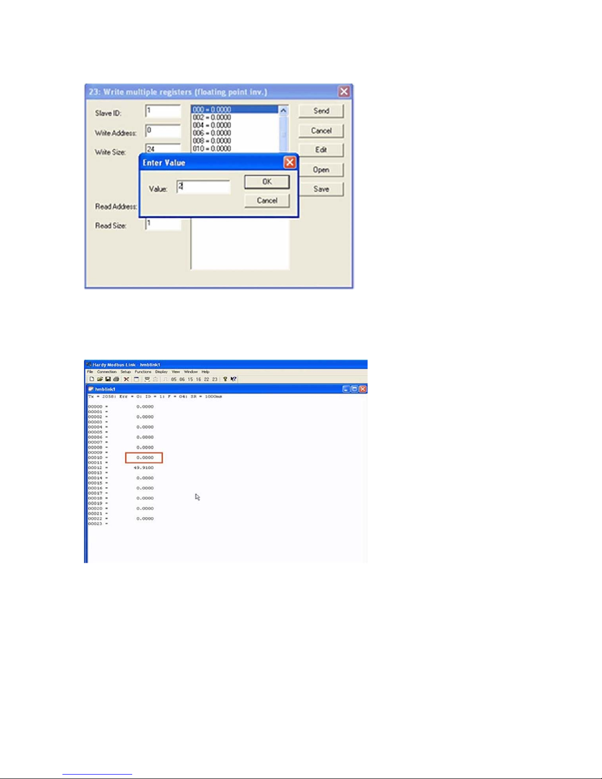
HI 6600 Series Modular Sensor System User Guide
10) Click on OK to accept the value and click on the Send button to send it to the HI 6600. Click OK to the
Response OK message.
11) Change the display back to Float Inverse and notice that our Tare command has
caused the Net weight to
change to zero
Page | 66
Page 67

HI 6600 Series Modular Sensor System User Guide
Profibus-DP
The Profibus®-DP (Decentralized Peripherals) communication profile is designed for efficient field-level
data exchange. Central automation devices, such as PLC/PC or process control systems, communicate
through a fast serial (RS-485) connection with distributed field devices, e.g. PLCs.
To begin communicating weighing parameters between an HI 6000 Series controller and a PLC, PC or DCS
system controller, you need only to load the *.GSD file and set the node address.
Wiring: For Profibus, connect the two wires to pins 3 and 4.
GND SHIELD TX+ TXSignal
Ground
Profibus Configuration
Profibus-DP operates using a cyclic transfer of data between master(s) and slave(s) on an RS-485 network.
An assigned master periodically requests (polls) each node (slave) on the network. The HI 6600 is a slave
device. All data communication exchanges between a master and the HI 6600 originate from the master
device. Each HI 6600 is assigned to one master and only that master may write output data to that HI 6600.
Other masters may read information from any slave, but can only write output data to their own assigned
slaves.
Because Profibus uses a cyclic (periodic) polling mechanism between masters and slaves, it is also
deterministic. Therefore, behavior of a Profibus system can be reliably predicted over time. Profibus is
designed to guarantee a deterministic response.
The length (and timing) of the I/O data to be transferred from a single slave to a master is predefined in the
slave's device data base or GSD file. The GSD files of each device connected via the network (slaves and
class 1 masters only) are compiled into a master parameter record which contains parameterization and
configuration data, an address allocation list, and the bus parameters for all connected stations. A master uses
this information to set up communication with each slave during startup. Slaves can only acknowledge the
messages they receive or transfer messages to a master when the latter requests a slave to do so. Slaves are
also designated as passive nodes.
Refer to the section, “I/O Tables For Communications to PLCs,” in Appendix A for an understanding of
the data and format for the Profibus communications.
For a full list of command parameters, please see the "Default Parameter IDs and Values" in Appendix B.
Do NOT
Connect
TXD+ /RXD+
Non-inverting
TXD-/RxDInverting
NOTE
Profibus-DP provides a very flexible network solution. In addition to the basic
guideline provided in this manual, your installat ion could require procedur es that
beyond the scope of this manual. For more information and to locate lists of
are
links to
other sources of Profibus-DP in form ation, check t he Profibus website at
http://www.profibus.com.
Page | 67
Page 68

HI 6600 Series Modular Sensor System User Guide
Configuring PROFIBUS from the Web Interface
1) From the web connection, choose Gateway > Configuration > Communications > Profibus. then Click on
Profibus Card. to open then Click on Profibus Card form. Double
current entry. Type in the HI 6600 Node address. Range:1-125 (default 5). The example below uses the default
address #5.
NOTE
2) Profibus on the HI 6600 Gateway does not have the Termination setting. The board has a switch on
Profibus Node Addre ss #5 is the lowest number that can be used by a slave device.
it for turning on/off the termination. The switch is located next to the Profibus connector. The
switch and connector is also used for the Modbus RTU and the switch position is: Center = off,
termination for Profibus is to the right labeled T2 (to the left is termination for Modbus RTU labeled
T1).
click in the Node text field to highlight the
3) Click Save Parameters to save the entry.
4) You can also read the communication state of the instrument (Active or Passive)
5) Click Home to return to the Home Page.
Initialization Process
To be able to add an HI 6600 to a Profibus-DP network, you need a PC or a PLC and software such as
Siemens Step 7™, Simatic Manager or the equivalent. The software must allow the Profibus-DP PLC and
the HI 6600 to exchange data.
Page | 68
Page 69

HI 6600 Series Modular Sensor System User Guide
Profibus-DP .GSD F ile
All devices connected to a Profibus-DP network require a *.gsd file. The *.gsd file contains all the parameters
including the baud rate, table formats and necessary data required by the network PLC when an HI 6600 is
connected to the network.
Yo u must download the proper *.GSD file from the Hardy website.
1) Navigate from the products section to the HI 6600 web page.
2) Click on the Tab, Docs & Programs and scroll down to Documents and Programs.
Select the *.GSD option to download the file.
Regardless of which Simatic Manager you use, you must go through these three steps:
1) Connect the HI 6600 Series Instrument to the Profibus DP network and verify the address.
(See the Installation Section for Installation and Cabling Instructions.)
2) Connect the PC to the Trunk Line. Load the configuration properties to the
software on the PC and transfer them to the PLC.
3) Install the *.gsd file.
Pre-Initialization Procedures
1) Inspect the network cables and make sure that the cables have been installed correctly and
satisfy the Profibus-DP guidel ines for the data transm ission baud
Cabling Chapter/Profibus Installation in this manual for
and cabling guidelines.)
2) Select the Node address for the HI 6600 as shown above. This can be done before or
after Initialization.
3) Cycle power, or perform the two previous steps before powering up your network. Address selection
can only occur after cycling the power. Make sure that the software you use will detect the values as
you have set them.
CAUTION: The address should never be changed during operation. If the address is
modified while on line, an internal error could be generated and the instrument
disconnected from the network.
ATTENTION L’adresse ne devrait jamaisêtre changée durant le
fonctionnement. Si l’adresse est modifiée pendant la miseen ligne, une erreur
interne pourrait être créée et le module sera déconnecté du réseau.
Profibus-DP cable specifications
initialization
rate(s) required. (See the
4) Complete any additional configuration that is required by your PLC for
initialization. Our initialization example is for a Siemens PLC. Your PLC
initialization requirements may differ.
5) Install the *.GSD file for the instrument you connected to the Profibus Network.
Page | 69
Page 70

HI 6600 Series Modular Sensor System User Guide
Configuring Profibus from the Front Panel
1) Press the Configuration key
2) Down arrow to Communications; press ent er.
3) Select Profibus-DP; press enter.
4) Down arrow to select Serial Option;
5) Press enter to toggle between Profibus-DP and Modbus. Select Profi bus-DP and
6) Down arrow to Node.
7) Press enter to make changes to the Node. Use the arrow keys to enter node number
8) Press exit key until display returns to the Summ ary Display.
Initialization Procedures on the PLC
NOTE
1) In the Siemens Step 7™, Simatic Manager, open the Hardware Catalog.
2) Click on the “+” to expand the Additional Field Devices Folder.
3) Click + to expand the General Folder.
The examples b e l o w come from the Siemens Step 7®, Simatic Manager Softwa re. Your soft ware will
vary from these proce dures. Step 7™ is a trademark of the Siemens Corporation.
press enter.
and press enter to accept
4) Double Click on “HI6000” or drag and drop the “HI6000” folder to the Profibus-DP Network. This
opens the HI 6000 PDP Parameters dialog box where you can set the address of the instrument, if
necessary.
Page | 70
Page 71

HI 6600 Series Modular Sensor System User Guide
4) Click OK to set the Node Address.
5) The HI 6600 Series module appears in the Profibus Network.
6) Click in the module properties at slot 1. In the catalog, expand the module properties
and make selection for "176 bytes in and out".
Page | 71
Page 72

HI 6600 Series Modular Sensor System User Guide
Page | 72
9) Once the selection has been made, you should see the input and output words showing the associated
addresses in the table as shown.
NOTE
The HI 6600 Series Input and Output Sizes ar e expressed i n 32-bit words with 44 words inp ut and 44
words output for the common header and the 10 channels
Page 73

HI 6600 Series Modular Sensor System User Guide
7) Click the Download Icon to download the configuration to the PLC and open the Select Destination
Module dialog box.
8) Click OK to open the Select Station Address Dialog box; then click OK again. A status box will
show the progress of configuration download to the PLC.
When the download is complete the HW Config dialog box sho uld look something like this.
9) Initialization is Complete
Page | 73
Page 74

HI 6600 Series Modular Sensor System User Guide
Modbus-RTU (over RS-485)
Modbus -RTU Commands and Parameters
Slave Address Parameter
The Slave Address parameter is a unique network address between 1 and 247 assigned to the HI 6600
series instrument.
On the Web page: select the communication m enu and t hen select the Modb us RTU
click inside the Slave Address text field and enter the Slave
instrument.
submenu, and left
Address assigned to the HI 6600 series
On the HI 6110 optional display: select the communication menu and use the UP or DOWN button to
select the Modbus-RTU submenu, then select the Slave Address
value will be displayed, press the ENTER or
the RIGHT button if the Slave Address needs to be modified.
Baud Rate Parameter
No specific baud rate is specified for Modbus-RTU, the Baud Rat e parame ter is use d to match the baud rate
set by the master device, typically 9,600 or 19,200.
On the Web page: select the communication m enu and t hen select the Modb us RTU
click inside the Baud Rate text field and enter the Baud Rate.
menu item. The current Slave Address
submenu and left
Page | 74
Page 75

HI 6600 Series Modular Sensor System User Guide
On the HI 6110 optional display: select the communication menu and use the UP or
select the Modbus-RTU submenu, then select the Baud Rate menu
displayed, press the ENTER or the RIGHT
button if the value needs to be modified.
item. The current Baud Rate value will be
Parity Parameter
The Parity parameter has three options, EVEN, ODD, or OFF.
On the Web page: select the communication menu and then select the M odbus RTU
click inside the Parity field and select even, odd or off using the
On the HI 6110 optional display, sel ect the com muni cation me nu and u se the UP or
the Modbus-RTU submenu, then select the Slave Address
displayed, press the ENTER or the RIGHT
1) Setup a slave address assigned to the HI 6600 series instrument from the
Modbus-RTU submenu.. Use a unique address
2) Set the Baud Rate to the same as the master device, typically 9600 or 19,200
parameter to match that of the Modbus-RTU master (EVEN,ODD, or OFF)
button if the Parity needs to be modified.
between 1 and 247
drop down menu.
menu item. The current Parity value will be
communications menu and the
Step 3. Set the Parity Bit
submenu, and left
DOWN button to select
DOWN button to
The RS 485 half duplex pinout is:
GND SHIELD TX+ TXSignal
Ground
Page | 75
Do Not
Connect
TXD+ /RXD+
Non-inverting
TXD-/RxD-
Inverting
Page 76

HI 6600 Series Modular Sensor System User Guide
Modbus Setup
• Slave Address may be set to any number in the range of 1-247.
• Set Baud Rate parameter to match the settings of the Modbus master
• Set Parity to match the settings of the Modb
Modbus Functions
The Modbus functions allowed in the HI 6600 are:
•
Function 3: Modbus Read Holding Registers
•
Function 4: Modbus Read Input Registers
• Function 6: Modbus Write Single Register
• Function 16 (0x10): Modbus Write Multiple Registers.
Note: See the Data Tables in Appendix A for command format information.
The Modbus master sends a 'command' by writing a value to re gister 0. Any non-zero return value
is an error.
Here is a list of Hardy command numbers:
• 0: READ PARAM CMD. To read a parameter, write a #0 to the command register
(register #0), and write the parameter number in the parameter ID number in registers 2 and
3, most significant word first. The parameter value may then be read from registers
again most significant word first. This value may be in integer or floating point
depending on the param eter. The status register in the reply will contain the
the system stat us word.
o Status word bit 0: A/D erro r.
o Status word bit 6 (0x40): Motion status.
o Status word bit 15 (0x8000): Not Found - the requested parameter number does
not exist
4 and 5,
format,
lower 16 bits of
• 1: ZERO CMD. Write a #1 to the command regi ster to ZERO the gross weight. The
status register will read 0 if this command succeeds.
o Status Error code 1 (motion)
o Status Error code 2 (A/D error)
o Status Error code 3 (out of tolerance)
o Code 0xFFFF indicates the command is in progress.
• 2: TARE CMD. Write a #2 to the command register to ZERO the net weight. The status
read 0 if this command succeeds:
o Status Error code 1 (motion)
o Status Error code 2 (A/D error)
o Code 0xFFFF indicates the command is in progress.
register will
• 4: WRITE NONVOL CMD. Write a #4 to the command register to save parameters in non-
volatile memory.
o No Error Codes
• 5: CMD: Reserved
o No Error Codes
Page | 76
Page 77

HI 6600 Series Modular Sensor System User Guide
• 6: WEIGHT SAMPLE CMD: Write a #6 to the command register to run the Weigh
command to set up the calibration of the Counts (if enabled).
o Status Error code 1 (motion)
o Status error code 2 (A/D error)
• 0x64 (100 decimal): CAL LOW CMD. Write a 0x64 hex to the command register to
step of a traditional calibration. The status register will read 0 if this
o Calibration_Fail 1
o Calibration_Fail_Motion 3
o Calibration_Fail_Adc_Error 4
o Code 2 indicates that the Calibration is in progress
command succeeds:
• 0x65 (101decimal): CAL HIGH CMD. Write a 0x65 hex to the command regi ster to
step of a traditional calibration.
o
Calibration_Fail 1
Calibration_Fail_Motion 3
o
Calibration_Fail_Adc_Error 4
o
o HardcalFailCounts 8: not enough counts between Hard Cal High and Hard Cal Lo
o Code 2 indicates that the Calibration is in progress
• 0x66 (102 decimal): C2 CAL CMD. Write a 0x66 hex to the comm and register to
calibration.
o Calibration_Fail 1
o Calibration_Fail_Motion 3
o Calibration_Fail_Adc_Error 4
o Calibration_Fail_Noc2 5
o Calibration_Fail_C2capeq 6
o Calibration_Fail_C2clones 7
o Code 2 indicates that the Calibration is in progress
• 0x1000 (4096 decimal): WRITE INTEGER CMD. Set the value of an integer
parameter. W rite 0x1000 in the command register 0, the paramete r ID number i n
registers 2, 3 and the desired value in registers 4, 5.
• No Error Codes
• 0x1001 (4097 decimal): WRITE FLOAT CMD. Set the value of a floating point
parameter. Write 0x1001 in the command register 0, the parameter ID num ber in
registers 2, 3 and the desired float value in registers 4, 5.
• Failure 1
• TooHig h -1 : value is above legal limit
• TooLow -2 : value is below legal limit
• ErrorNotFound 0x8000 : parameter id not found
perform the low
perform the high
perform a C2
Sample
USB Memory Stick
The HI 6600 series provides an interface to an external USB memory stick that allows HI 6600 parameters to
be saved, modified, restored or copied to another instrument.
To begin, insert a USB stick into the Gateway Module, navigate to the Communications section of the Setup,
select USB, then select Save or Restore. The USB memory stick commands can be activated through the web
Page | 77
Page 78

HI 6600 Series Modular Sensor System User Guide
interface or the display panel.
Note: The Update USB Status found in web interface serves as a page refresh and should be clicked
after a USB stick is inserted.
Restore Command
This command replaces the existing HI 6600 system parameters with the parameters stored on a USB
memory stick. Parameters may be removed or modified in the .txt file as required before using the restore
command (for example – if only the IP address needs to be restored, erase all other parameters in the .txt file,
leaving only the following: 00003101 Fixed IP=198.163.0.10 0.
The user can create a restore.txt file that will automatically be loaded if located on the USB drive at power
up.
The contents for the restore.txt file can be generated in two ways.
1. Use a saved copy of the parameters on a USB stick
a. Insert a USB stick into the HI 6600 Gateway Module
b. Save the parameters to a USB stick
c. Connect the USB to a PC or laptop
d. Find the params.txt file within the model’s sub directory (e.g. HI 6600/params.txt)
e. Rename the params.txt file to restore.txt
f. Remove or Modify parameters in the .txt file as required
g. Save the restore.txt file back into the model’s sub directory (e.g. HI 6600/restore.txt)
2. Use a copy of the parameter.txt file from the web browser
a. Connect the instrument to a PC
b. Copy the parameter.txt file from the web browser (found in the diagnostics menu)
c. Rename the parameter.txt file to restore.txt
d. Remove or Modify parameters in the .txt file as required
e. Remove or Modify parameters as required
f. Connect the USB to a PC
g. Save the restore.txt file into the model’s sub directory (e.g. HI 6600/restore.txt)
Page | 78
Page 79

HI 6600 Series Modular Sensor System User Guide
b
d
p
b
d
p
but
d
p
N
Chapter 7
Security
• • • • • •
Chapter 7 covers the security menu, which allows the user to lock out different levels of the menu hierarchy.
The user configurable security settings only limit access through the Optional Front Panel to ensure the
consistency of the instrument setup and weighing process. Parameter configuration through the network is
unaffected by these security settings.
Note: Security settings are universal and are applied to all channels on the system. For example, if
Calibration Security is selected, then a password is required to calibrate ANY Weight Processor
Module on the System.
Optional HI 6110 Display Security Options
Lock Enabled Operation
Display Displayisblank;andthe Mode,Tare,Zero, and Configuration
Keypa d Display is active; and the Mode, Tare, Zero, and Configuration
Confi gurat ion Display is active, and the Mode, Tare, and Zero buttons are active;
Read Only
Calib ra ti o n Display is active, all buttons are active, and all the parameters
o Locks Enabled
uttons are disabled. Pressing ENTER jumps to the passwor
rompt.
uttons are disabled. Pressing ENTER jumps to the passwor
rompt.
theconfigurationbutton is disabled. Pressing CONFIG jumps
to the configurationpasswor
Display is active, and the Mode, Tare, and Zero buttons are active,
the configurationbutton is activebutnoparameters can be
modified.
exceptthe calibrationparameters canbe modified.
When no locks are selected, the display is active, all buttons are
active, andall theparameters canbe modified.
rompt.
The current status and password for each level of security can be read and changed through the web browser
if using an Ethernet connection, or through the serial interface.
To access or modify the security parameters through the Optional Front Panel display, a password always
needs to be entered before a lock can be enabled or disabled or the password modified. Note, that as the
password can be read over the network, any security password can always be over written if the local
operator enters an incorrect password.
Page | 79
Page 80

HI 6600 Series Modular Sensor System User Guide
The changes to the calibration and read only security features are updated when you exit the security
submenu and return to the configuration menu; while changes to the display, keypad, or configuration
security settings are updated when the operator exits the configuration menu.
The factory default for the security menu is to disable all lock modes and to preset each of the security
passwords to 1234.
NOTE:
Once set, the security parameters can only be accessed via the Optional Front Panel display by
entering a preset password, or directl y through t he network con nection.
the security password. We recommend you keep your
passwords in a secure location.
There is no way to bypass
The Display Lock
The Display Lock disables and blanks the Optional Front Panel display and disables the keypad. If the
ENTER button is pressed, a password dialog box is shown on the screen. If the correct password is entered
the display is unlocked and operator can view the weight data and use the MODE button to change the weight
between Gross and Net. If the ENTER button is pressed again the Display Lock parameter is reset to
ENABLED and the display blanked. This security setting blanks the front screen so the current weight
reading on the scale cannot be observed; and while the display is locked the Mode, Zero, Tare, and
Configuration buttons are disabled regardless of the keypad lock or configuration lock settings; as enabling
these buttons without the operator being able to read the Optional Front Panel display would lead to process
errors.
If the ENTER button is pressed the “Enter Password” page will appear on the display. At this level of security
the operator can enter one of three possible passwords for the display lock, the keypad lock, or the
configuration lock.
NOTE
If the keypad is locked, then the tare, ze ro , mode, and configuration buttons ar e disabled
Page | 80
Page 81

HI 6600 Series Modular Sensor System User Guide
The display lock flowchart below shows the options and features when the display lock is
Figure 1: Disp lay Lock Flowchart
enabled.
Page | 81
Page 82

HI 6600 Series Modular Sensor System User Guide
The following list explains the operation and features available if the correct 4
entered by the operator.
1) Display Password:
The current display lock setting is saved.
The display lock is set to disabled and the MODE button is unlocked,
the current Gross or Net weight on the
Optional Front Panel display.
Pressing the ENTER button a second time returns the display lock to its
2) Keypad Password:
The current display lock and keypad lock settings are saved.
The display lock is set to disabled and the MODE, TA RE, and ZERO buttons
operator to view the current Gross or Net weight
on the Optional Front Panel disp lay, and t o tare or zero
the scale.
Pressing the ENTER button a second time returns the display lock and
settings.
3) Configuration Password:
The current display lock, keypad lock, and configuration lock setting are
The display lock is set to disabled and the MODE, T ARE, and ZERO buttons
operator to view the current Gross or Net weight
on the Optional Front Panel displa y, and to t are or zero
the scale.
The CONFIG button is also enabled allowing the operator to open the
When the operator exits the configuration menu, the display lock and keypad lock are
original settings. If no changes to the configuration lock or password
configuration lock is also set to its original lock settings;
otherwise the latest configuration security
settings are used.
alphanumeric character password is
enabling the operator to view
original setting.
are unlocked, enabling the
keypad lock to their original
saved.
are unlocked, enabling the
configuration menus.
parameters were made the
set to their
Page | 82
Page 83

HI 6600 Series Modular Sensor System User Guide
The Keypad Lock
While the keypad lock is enabled the Mode, Zero, Tare, and Configuration buttons are disabled regardless of the configuration
lock setting.
If the ENTER button is pressed the “Enter Password” page will appear on the display. At
enter one of two possible passwords for the keypad
lock or the configuration lock.
The keypad lock flowchart below shows the options and features when the keypad lock is
this level of security the operator can
enabled.
Figure 2: Keypad Lock Flowchart
Page | 83
Page 84

HI 6600 Series Modular Sensor System User Guide
The following list explains the operation and features available if t he correct 4
password is entered by the operator.
1)
Keypad Password:
The current keypad lock setting is saved.
The MODE, TARE, and ZERO buttons are unlocked, enabling the operator
Pressing the ENTER button a second time returns the keypad lock to its
2)
Configuration Password:
The current keypad lock and configuration lock setting are saved.
The TARE and ZERO buttons are unlocked, enabling the operator to tare or
The CONFIG button is also enabled allowing the operator to open the
When the operator exits the configuration menu, the display lock and keypad
changes to the configuration lock
lock settings; otherwise the latest configuration security settings are
or password parameters were made the configuration lock is also set to its original
The Configuration Lock
While the configuration lock is enabled the Confi guration button is disabled, preventing the operator from viewing or modifying
any instrument parameters.
If the CONFIG button is pressed the “Enter Password” page will appear on the di splay. At
enter only one possible password for the configuration
The configuration lock flowchart shows the options and features when the configuration
lock.
alphanumeric character
to tare or zero the scale.
original setting .
zero the scale.
configuration menus.
lock are set to their original settings. If no
used.
this level of security the operator can
lock is enabled.
Page | 84
Page 85

Figure 3: Configuration Lock Flowchart
HI 6600 Series Modular Sensor System User Guide
The following list explains the operation and features available if the correct 4 alphanumeric character password is
entered by the operator.
Configuration Password:
Page | 85
The current configuration lock setting is saved.
The CONFIG button is also enabled allowing the operator to open the
When the operator exits the configuration menu, if no changes to the
parameters were made the configuration lock
configuration security
settings is used.
is set to its original lock settings; otherwise the latest
configuration menus.
config uration lock or password
Page 86

HI 6600 Series Modular Sensor System User Guide
The Read Only, Security & Calibration Locks
There are three additional levels of security once the operator is within the configuration menu. These limit access to
sensitive parameter settings such as calibration, security settings, and network settings.
If the operator has been given permission to access the configuration menu, the operator will at a minimum be able to
view all the parameters except the security parameters.
Figure 4: Parameters Lock Flow Chart
Page | 86
Page 87

HI 6600 Series Modular Sensor System User Guide
Modifying the Security Parameters
To view or modify the security parameters use the UP or DOWN button to select the security menu then press ENTER.
Figure 5: Parameters Lock Flow Chart
To modify the security feature use the UP or DOWN button to select the security feature then press the ENTER button.
The password dialog box will appear; if the correct 4 alphanumeric character sequence is entered the operator will be able
to either enable or disable the security feature or change the password. Note a password must consist of a 4 alphanumeric
character sequence to be accepted as a valid password.
If an incorrect password is entered the menu will be returned to the security submenu.
The updated security features for the Read Only Lock and Calibration Lock will not be active until the operator leaves the
security menu, any changes for the Configuration Lock, Keypad Lock, or Display Lock will not be active until the
operator exits the configuration menu and returns to the top level display.
Page | 87
Page 88

HI 6600 Series Modular Sensor System User Guide
Modifying the Calibration Param eters
The calibration security locks out users from seeing any calibration parameters until you enter the correct calibration
password.
To modify the calibration parameters use the UP or DOWN button to select the calibration menu and press the ENTER
button. The password dialog box will appear; if the correct 4 digit alphanumeric character sequence is entered the
calibration lock will be disabled until you exit the calibration menu; at which time the calibration lock will be
automatically reset to the original setting.
If an incorrect password is entered the menu will return to the configuration menu.
Modifying the Read Only Parame ters
The security and calibration parameters have their own password protection. The parameters discussed in this section are
those listed under communication, diagnostics, display, filter, language, operation, and setup.
With the exception of the security and calibration parameters, all parameters can be read by the operator once the operator
is navigating inside the configuration menu; however the ability to change these parameters can be password protected.
If the read only password is enabled and a parameter is selected, the password dialog box will appear. If the 4
alphanumeric character sequence is entered the read only lock will be disabled until you exit the configuration menu; at
which time the configuration lock will be automatically reset to the original setting.
If an incorrect password is entered, the menu will return to the configuration menu.
Page | 88
Page 89

HI 6600 Series Modular Sensor System User Guide
Chapter 8
Troubleshooting
• • • • • •
Chapter 8 provides procedures for troubleshooting the electrical, mechanical and firmware elements of the HI 6600 series
instrument and for using Hardy’s Integrated Technician (IT®) software utility to isolate problems. Flow charts provide
troubleshooting procedures for the Gateway Module, the WPM modules, load cells, and cabling.
NOTE
Never run Hardy’ s Inte grated Tec hni ci an testing while in a production mode. The reported
weight readings will not be correct and can cause equipment to start or stop
unpredictably.
Assembly Notes, Warnings & Cautions
WARNING - EXPLOSION HAZARD - DO NOT REPLACE COMPONENTS
UNLESS POWER HAS BEEN SWITCHED OFF OR AREA IS KNOWN TO BE NONHAZARDOUS.
A V ER TISSEM ENT – Risque d’explosion- Ne pas rem placer les composants à
moins que la source d’alimentation soit éteinte ou que la zone est classifiée non
dangereuse.
WARNING - EXPLOSION HAZARD - DO NOT DISCONNECT EQUIPMENT
UNLESS POWER HAS BEEN SWITCHED OFF OR THE AREA IS KNOWN TO BE
NON-HAZARDOUS
AVERT IS SE ME NT – Risque d’explosion – Ne pas déconnecter l’é quipement à
moins que la source d’alimentation ait été mise en position « éteint » ou que la
zone soit classifiée non dangereuse.
Always disconnect the power cord before disassembling.
Always replace broken or damaged module s or har dw are i mmediately.
Always check to be sure that no loose parts are sitting on printed circuit boards or electrical connectors or wires
when disassembling or reassembling.
Always protect printed circuit boards from electrostatic discharge (ESD). Always use approved ESD wrist straps
and anti-static pads.
Page | 89
Page 90

HI 6600 Series Modular Sensor System User Guide
This chapter describes several tests that can shorten the time for troubleshooting. Most problems require the use of two or
more tests to determine the cause.
If a problem is isolated to a load cell, it may not mean the load cell is the damaged component. Mechanical imbalances
and system piping stress (lack of piping flexures, pressu re hoses draped over, pipes etc.) can make a load cell or Weight
Processor Module seem to be the problem.
If you are in doubt as to how to resolve a problem or if you need assistance, review Hardy’s WebTech Knowledgebase at
http://www.hardysolutions.com. WebTech is updated often and is available 365 days a year 24/7. It contains frequently
asked questions to aid you in troubleshooting, and it provides a form for requesting additional information and answers to
questions, with no waiting on hold. Located under the Support menu, select the FAQs.
Customer Service is also available from 6:30AM to 5:30 PM Pacific Standard Time. For direct factory support call Hardy
Process Solutions Customer Service at:
Factory Technical Support in the US and Canada: 1-800-821-5831
Techni cal Support outside t he US and Canada : 1-858-278-2900
Updating Instrument Firmware
Firmware should be updated to the latest release before proceeding with troubleshooting.
Information Page
The information page displays the firmware versions and description of the HI 6600 series instrument and can be
accessed either through the Webrowser or optional Front Panel Display.
By Clicking on the All WPM Versions link, it displays information for the connected HI 6610 WPMs.
It also is where firmware updates for the HI 6610 WPMs can be initiated.
Page | 90
Page 91

HI 6600 Series Modular Sensor System User Guide
To change to a different WPM Channel, just select it from the pull down menu.
To update firmware on a WPM version, first select it and change the channel, then select
Indicator Lights Summary
Weight Processing Module
Green LED
1 off
2 off
3 off
4 off
5 solid
6 slow blinking
7 fast blinking
8 slow blinking
9 fast blinking
Red LED
off
solid
slow blinking
fast blinking
off
off
off
slow blinking
fast blinking
Hardy Gateway Module
Green LED
1 off
2 off
3 off
4 off
5 solid
6 slow blinking
7 fast blinking
8 slow blinking
9 fast blinking
Red LED
off
Solid
Slow bllinking
fast blinking
off
off
slow blinking
fast blinking
fast blinking
Definition
No Power, or ARM not programmed
HardyNet network failure
Built-in self-test failure
Low Power indication
Normal operation
Unit identification
Unit being programmed
Load cell current issue
Measurement errors
Definition
No Power, or ARM not programmed
HardyNet network failures
Built-in self-test failure
Low Power indication
Normal operation
Unit identification
Unit being programmed
Network error (no comms)
DSP error
Begin Programming.
Page | 91
Page 92

HI 6600 Series Modular Sensor System User Guide
Common Error Messages
A/D Convert Error! - Load Cells input out of range.
Motion Error! - Check Motion Tolera nce Settings and Retry
Too Lo Error! - Ve rify that the load cell signal level is 0-25 mV . Ve rify that there is
the scale.
Too Hi Error! - V erify that the load cell signal level is 0-25mV . V erify that there is too
the scale.
No C2 Sensor! - Instrument did not dete ct a C2 Load Sensor
CAL Failed! - Too few counts between Zero and Span.
C2 Caps Unequal! - Different load cell capacities (For example 50 lbs capacity load cell
on one system. Make the load cells equal by removing t he
the other’s capacity.
HI/LO Too Close! - Zero and Span are not more than 1,000 counts from each other or
change. Reset either so the counts are more than 1,000
Not Allowed! - Valu e entered is outside the range allowed. Try another value.
Need Cal with ITJBOX - IT summing card is not installed. Install an IT summing card
card installed to access the IT information.
odd load cell and replacing it with a load cell that is equal to
counts of each other.
enough weight on
much weight on
and 100 lbs capacity load cell
there is no change or negative
then do a Calibration with the
Diagnostics
Diagnostics is covered extensively in the Troubleshooting Section (Chapter 8). The available parameters on the Web
page are:
The available parameters on the device are:
Trouble Shooting Using Integrated Technician (IT®)
The Optional Front Panel display for the HI 6600 instrument’s Stability test is shown below. To navigate this screen, select a test
on the right using the right and l eft arrows with exit
The test displays are live readings and only available if you have an IT summing junction
Page | 92
Parameters (which shows all parameters on the instrument)
Integrated Technic ian (when connected to an IT Junction Box)
C2
Stability Test
Stability Test
Weight and V oltage Test
using the left arrow when y ou are at the first out of the five positi ons.
card, maximum of one J-box and 4
Page 93

HI 6600 Series Modular Sensor System User Guide
r
channels to each HI 6610 Wei ght Processing Module.
The test for pass or fail may take 30 seconds to settle. It will always show the load cells as
The reduced voltage is a Ye s or No selection. Then run the J-box test 1 as appropriate.
A more detailed explanation of each section of the test follows below:
fail when the test is started.
Stability Test ALL
Stability:
Mean
Variation
Results
mV/V
RTZ
PASS/FAIL and Stability Test
This test computes the variation of the A/D counts. The results show the variance and indicate pass or fail. The test
is valid to help break down the problem into smaller divisions.
A/D processor fault, grounding, power
These numbers reflect a weight change at the smallest measurement of the filter setting, the
converter computer register.
WAVERSAVER TEST
These numbers also reflect weight change at the smallest measurement, the internal analog- to-digital converter
compute r regist er. The internal RA W A to D counts and filtered A to
A FAI L o n the R A W co unts and pass on the
necessary and functioning
AVERAGES
averages and the 10ms update speed equals a maxim um delay of 2.55 seconds
setting parameter from the Processor’s configuration. Using the maximum number of internal
Gross = 0.9lb
RAW
32918
0.17
OK
0.0184
Pass
properly.- except that this reading is averaged using the WAVERSA VER and
Waversave
32993
0.00
OK
Unstable test results can be caused by an internal
connection, EMI/RFI above specified CE limits, or noisy load cell input.
internal analog-to-digital
D counts are displayed for a comparison.
filtered counts indicates the WA VERS AVER filtering is
Weight and Voltage ALL
This test section looks at the readings from ALL the load cells to test overall system performance and signal
voltage readings. This test works for most load cell types.
Page | 93
Page 94

HI 6600 Series Modular Sensor System User Guide
Further investigation to isolate system problems requires t he use of
hand tools and multi-meters or the INTEGRATEDTECHNICIAN
Junction or Summing Box and
NOTE
INTEGRATED TECHNICIAN ® (IT) is a registered
trademark of Hardy Process Solutions.
Weight This displays the amount of force seen by all load cells
installed in the summing
system problems will require the use of hand
test
section.
Millivolt/V olt equals the output from a load cell per each volt of excitation. The HI 6600
mV/V which is a higher resolution (4 decimal places)
you to
troubleshoot the condition of the load cell in question under certain conditions. . Load Cells are rated in Millivolts/V olts.
mV/V are DC v oltage signal s between 0-5.0000 mV/V .
mV DC voltage signals are between 0-25 millivolts. Overloads and negative millivolt readings are not shown as actual readings
but 25.5 mVfor over voltage and 0.0 for negative
view the out
of range voltages.
using the IT© Test section.
junction box. Further investigation to isolate
tools and Multi-meters or the Integrated Summing Junction box and using the IT
reading than a mV reading, thereby providing more sensitivity to enable
voltage. Yo u will need to use a multimeter with a 200 or 300mVDC range to
series reads the load cell output in
RTZ (Return to Zero) Test
This check is to see if the scale returns to a zero reading condition when it is empty . Run this test only when the scale is empty.
When the scale is calibrated at the ZERO or
collected. After
current readings. If the difference is more than the combined Motion and the
a valid calibration has been completed, the test compares the original weight reading with collected and
Reference zero, there is a period during which the WEIGHT readings are
Zero Tolera nce parameters the test will fail.
IT Test
If your system has an Integrated Technician Summing Junction box, the IT test can identify individual load cell problems
up to a maximum of four load cell selections. The dwell displays are live readings and only available if you have an IT
summing junction card, with a maximum of one JBox and 4 channels. From the front display, select Jbox1.
From the HI 6610 WPM Diagnostics menu, select Integrated Technician.
Sensor Number Indicates which sensor is under test. Using the up or down arrow, select the number of load cells to test.
Page | 94
Page 95

HI 6600 Series Modular Sensor System User Guide
and press Do IT Test. The Dwell test for pass or fail takes 30 seconds to settle. Until it settles, it will always show “fail”
when the test is started. If the browser times out during the test, refresh your browser until the results appear.
NOTE
Warnin g: Do not install your Junction Box or summing card in areas susceptible to high
vibrations. The relays on the circuit board can c hatter and affect your weight readings.
Page | 95
Page 96

HI 6600 Series Modular Sensor System User Guide
General Troubleshooting Flow Chart Index
Page | 96
Page 97

HI 6600 Series Modular Sensor System User Guide
A - Electrical and Mechanical Review
Page | 97
Page 98

HI 6600 Series Modular Sensor System User Guide
A1. Checking for Unstable Components in a Weighing System
Page | 98
Page 99

HI 6600 Series Modular Sensor System User Guide
B. Guidelines for Electrical, Mechanical or Configuration Issues
Page | 99
Page 100
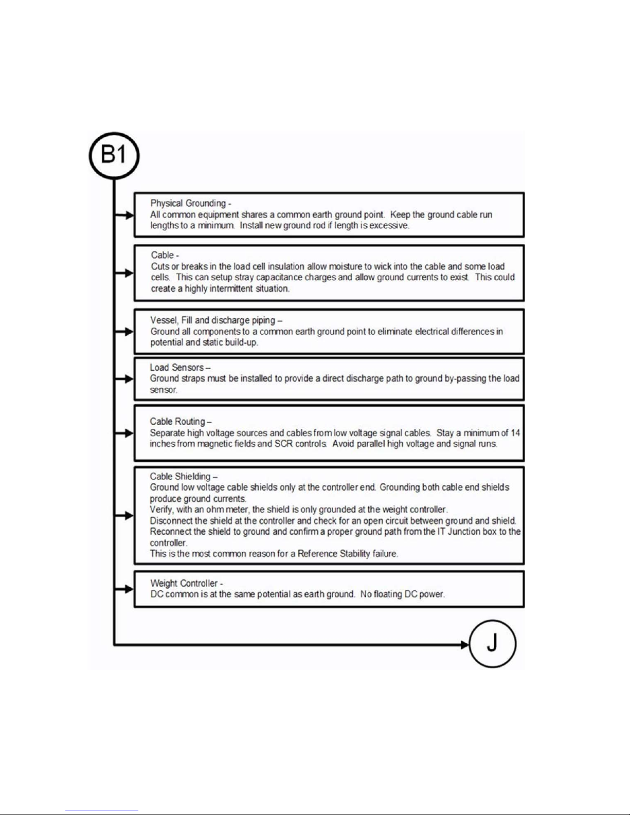
HI 6600 Series Modular Sensor System User Guide
B1 - Guidelines to Verify Electrical Installation
Page | 100
 Loading...