

Page 1
Herror!
HI 6200 Single Channel Weight Processor
User Guide
FastFind Links
Product Description
Installation
Initial Setup
Ways to Set Scale Parameters
Setting Scale Parameters
Troubleshooting
Hardy Installation and Commissioning
Page 2

Hardy Process Solutions
9440 Carroll Park Drive San Diego
San Diego, CA 92121
Copyright © 2019 Hardy Process Solutions
All Rights Reserved
Notice of Rights
No part of this manual may be reproduced or copied, translated or transmitted, in any form or by any
means, without the prior written permission of Hardy Process Solutions.
Notice of Liability
Information provided in this manual is intended to be accurate and reliable. However, Hardy Process
Solutions, Inc. assumes no responsibility for its use, nor for any infringement of rights of third parties
which may result from its use. THIS DOCUMENT IS PROVIDED “AS IS” AND ANY EXPRESS OR
IMPLIED WARRANTIES, INCLUDING, BUT NOT LIMITED TO, THE IMPLIED WARRANTIES OF
MERCHANTABILITY AND FITNESS FOR A PARTICULAR PURPOSE ARE DISCLAIMED. IN NO
EVENT SHALL HARDY PROCESS SOLUTIONS, INC. BE LIABLE FOR ANY DIRECT, INDIRECT,
INCIDENTAL, SPECIAL, EXEMPLARY, OR CONSEQUENTIAL DAMAGES (INCLUDING, BUT NOT
LIMITED TO, PROCUREMENT OF SUBSTITUTE GOODS OR SERVICES; LOSS OF USE, DATA,
OR PROFITS; OR BUSINESS INTERRUPTION) HOWEVER CAUSED AND ON ANY THEORY OF
LIABILITY, WHETHER IN CONTRACT, STRICT LIABILITY, OR TORT (INCLUDING NEGLIGENCE
OR OTHERWISE) ARISING IN ANY WAY OUT OF THE USE OF THIS DOCUMENT, EVEN IF
ADVISED OF THE POSSIBILITY OF SUCH DAMAGE.
Trademarks
All trademarks and registered trademarks are the property of their respective owners.
Hardy Process Solutions HI 6200 Weigh Processor User Guide Part Number 0596-0358-01, Rev A
Page 3

CONTENTS
How to Use This Guide ............................................................................................ 6
Introduction ............................................................................................................ 6
Audience ................................................................................................................ 6
Changes in This Revision ...................................................................................... 6
Related Documents ............................................................................................... 6
User Feedback ...................................................................................................... 6
Organization of the Guide ...................................................................................... 7
Document Conventions ......................................................................................... 8
1 Product Description ............................................................................................. 9
1.1 Overview ............................................................................................................. 10
1.2 Models ................................................................................................................. 11
1.3 Key Features ....................................................................................................... 12
1.3.1 WAVERSAVER
1.3.2 C2
1.3.3 INTEGRATED TECHNICIAN™ Operator Diagnostics ............................... 12
®
Electronic Calibration .......................................................................... 12
®
........................................................................................ 12
2 Installation ........................................................................................................... 13
2.1 Hardy Field Service ............................................................................................. 14
2.2 Pre-installation Planning ...................................................................................... 14
2.3 Unpacking ........................................................................................................... 16
2.4 Climatization ........................................................................................................ 17
2.5 Handling Precautions .......................................................................................... 17
2.5.1 Sources of Electrical Interference ............................................................... 1 8
2.6 Mounting the HI 6200 .......................................................................................... 19
2.7 Wiring the HI 6200 ............................................................................................... 21
2.8 Powering on the HI 6200 ..................................................................................... 22
3 Initial Setup ......................................................................................................... 23
3.1 Initial Setup .......................................................................................................... 24
4 Setting Scale Parameters ................................................................................... 26
4.1 Using the Touch Screen ...................................................................................... 27
4.2 Using the Embedded Webserver ........................................................................ 29
Hardy Process Solutions HI 6200 Weigh Processor User Guide 3
Page 4

4.2.1 Saving “Known Good” Parameters ............................................................. 32
4.2.2 Restoring from “KnownGood” Parameters ................................................. 34
4.3 Using a PLC ........................................................................................................ 36
4.3.1 EIP .............................................................................................................. 36
4.3.2 Setting Up Communications ....................................................................... 36
4.3.3 Configuration Parameters ........................................................................... 38
4.3.4 Configuration with AOP .............................................................................. 39
4.3.5 PLC Commands ......................................................................................... 39
READ PARAM CMD ............................................................................................ 40
ZERO CMD ......................................................................................................... 40
TARE CMD .......................................................................................................... 41
CAL LOW CMD ................................................................................................... 41
CAL HIGH CMD .................................................................................................. 41
C2 CAL CMD ....................................................................................................... 42
IT Test ................................................................................................................. 42
Stability Test ........................................................................................................ 42
IT Test Reduced .................................................................................................. 43
C2 Search ............................................................................................................ 43
WRITE CMD ........................................................................................................ 43
Set Default Parameters ....................................................................................... 44
Set Default Network Parameters ......................................................................... 44
Write to NVM (non-volatile memory) ................................................................... 44
Save Last Good Configuration ............................................................................ 44
4.3.6 Modbus ....................................................................................................... 45
5 Setting Scale Parameters ................................................................................... 54
5.1 Pre-Calibration Procedures ................................................................................. 55
5.2 Calibration Setup Procedures ............................................................................. 56
5.2.1 Unit of Measure .......................................................................................... 56
5.2.2 Motion Tolerance ........................................................................................ 56
5.2.3 Zero Tolerance ........................................................................................... 56
5.2.4 Auto Zero Tracking ..................................................................................... 56
5.2.5 Auto Zero Tolerance ................................................................................... 57
5.2.6 Number of Averages ................................................................................... 57
5.2.7 Span Weight ............................................................................................... 57
5.2.8 Ref Weight .................................................................................................. 57
5.2.9 Gravity Correction ....................................................................................... 57
5.2.10 Tare Weight .............................................................................................. 58
5.2.11 WAVESAVER® ........................................................................................ 59
5.3 Calibrating the Scale ........................................................................................... 60
5.3.1 Pre-calibration Procedures ......................................................................... 60
5.3.2 C2
®
Calibration ........................................................................................... 61
Hardy Process Solutions HI 6200 Weigh Processor User Guide 4
Page 5

5.3.3 Hard Calibration .......................................................................................... 61
6 Troubleshooting ................................................................................................. 62
6.1 Troubleshooting Table ......................................................................................... 63
6.2 Weighing System Test ........................................................................................ 64
6.3 Electrical Check Procedures ............................................................................... 64
6.3.1 Load Sensor/Point Input/Output Measurements ........................................ 64
6.3.2 Load Check ................................................................................................ 65
7 Hardy Installation and Commissioning ............................................................ 67
7.1 Emergency Service and Support ......................................................................... 67
Index ....................................................................................................................... 77
Hardy Process Solutions HI 6200 Weigh Processor User Guide 5
Page 6

HOW TO USE THIS GUIDE
Introduction
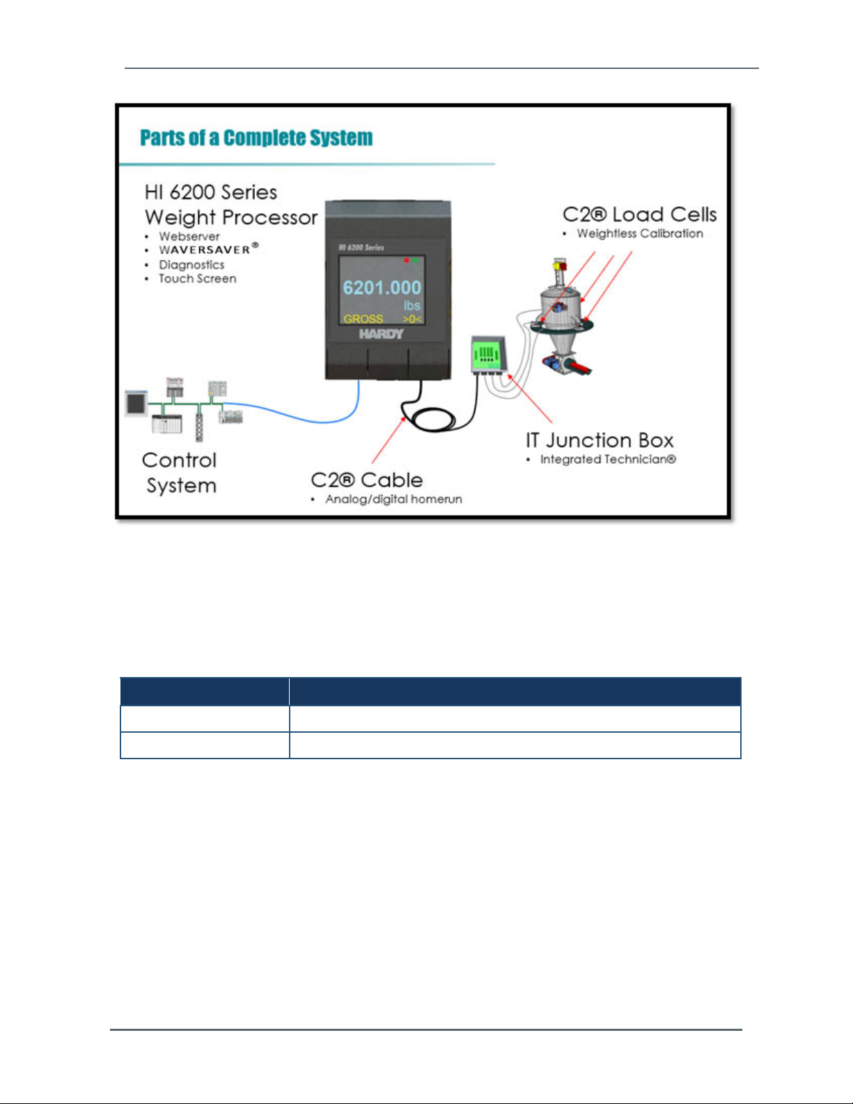
The Hardy Process Solutions HI 6200 Weigh Processor is a state-of-the-art product. It uses
advanced microprocessor technology and front-end signal processing of stain-gauge type
load sensors to provide super-accurate weighing coupled with operator-friendly interfaces
and reliability. These features make the instrument ideally suited for all types of industrial
manufacturing weighing applications.
To benefit from Hardy’s entire feature set of WAVESAVER®, C2® Calibration, and
INTEGRATED TECHNICIAN™ diagnostics, complete your scale system using all Hardy
components.
Do not operate or work on this equipment unless you have read and understand the
instructions and warnings in this manual. Failing to follow the instructions or heed the
warnings can result in injury or death.
Audience
This manual describes how to install, configure, operate, maintain, and troubleshoot the
HI 6200 Weigh Processor. It is intended for individuals responsible for installing, configuring,
operating, and servicing the HI 6200.
Changes in This Revision
N/A - this is first version of this document.
Related Documents
Hardy Process Solutions provides manuals in PDF format that can be downloaded from our
website free of charge. Go to http://www.hardysolutions.com/, click the Support Center link,
and then hover over Doc & Program Downloads for each product.
User Feedback
Hardy Process Solutions appreciates your business, and welcomes all corrections or
suggestions for improving this manual. Please send your comments to
hardysupport@hardysolutions.com. Include the document title, and refer to specific sections
and paragraphs whenever possible. All comments become the property of Hardy Process
Solutions. Thank you!
Hardy Process Solutions HI 6200 Weigh Processor User Guide 6
Page 7

How to Use This Guide
Organization of the Guide
Chapter 1 ‒ Product Description
This chapter provides an overview of the HI 6200, along with a description of the
available models and key features.
Chapter 2 ‒ Installation
This chapter describes how to install the HI 6200.
Chapter 3 ‒ Initial Setup
Describes the initial setup steps to perform before using the HI 6200 for the first time.
Chapter 4 ‒ WAYS TO SET Scale Parameters
This chapter describes the different ways to set HI 6200 scale parameters.
Chapter 5 ‒ Setting Scale Parameters
This chapter describes how to calibrate the HI 6200.
Chapter 6 ‒ Troubleshooting
This chapter provides information for identifying and resolving HI 6200 problems.
Chapter 7 ‒ Hardy Installation and Commissioning
This chapter describes Hardy product installation and commissioning.
APPENDIX A - Specifications
This appendix lists the HI 6200 specifications.
APPENDIX B - List of Parameter IDs
This appendix lists the parameter IDs for the HI 6200.
APPENDIX C - Frequently Asked Questions
This appendix provides answers to frequently asked questions.
Hardy Process Solutions HI 6200 Weigh Processor User Guide 7
Page 8
How to Use This Guide
Document Conventions
This document uses the following conventions to draw attention to certain information.
Terminology
In this guide, the terms “HI 6200,” “instrument,” and “system” are used interchangeably to
describe the Hardy Process Solutions HI 6200.
Safety and Warnings
Symbol Meaning Description
Note Notes emphasize or supplement important points of the main
Tip Tips provide helpful information, guidelines, or suggestions for
Caution Indicates a potential hazard or unsafe practice, which, if not
Warning Warnings indicate that failure to take a specified action could
text.
performing tasks more effectively.
avoided, could result in minor injury, harm to the patient or
operator, or damage to property or the device.
result in data loss or other serious consequences.
Typographic Conventions
Convention Description
Bold Indicates text on a window, other than the window title, including menus, menu
Italic or < > Indicates a variable, which is a placeholder for actual text provided by the user or
page/code
[ ] square brackets Indicates optional values.
options, buttons, fields, and labels.
system.
Indicates text that is displayed on page or entered by the user.
{ } braces Indicates required or expected values.
| vertical bar Indicates a choice between two or more options or arguments.
Hardy Process Solutions HI 6200 Weigh Processor User Guide 8
Page 9

1 PRODUCT DESCRIPTION
Topics:
Overview (page 10)
Models (page 11)
Key Features (page 12)
This chapter provides an overview of the HI 6200
Single Channel Weight Processor. This chapter also
lists the available models and describes the
instrument’s key features.
Hardy Process Solutions HI 6200 Weigh Processor User Guide 9
Page 10

Chapter 1 – Product Description
1.1 Overview
The HI 6200 series are high-performance, single-channel Weight Processors featuring
industrial Ethernet-based communication, Industrial Internet of Things (IIoT) compatibility,
remote diagnostics, and a user-friendly touch-screen interface. The HI 6200 is ideally suited
for OEMs and system integrators who build machinery where fast, stable weight data along
with low-cost of ownership are critical components to their successful design.
Ultra-compact at just 2 inches wide and 3 inches high, the HI 6200 series saves cabinet
space. This form factor allows for high-density panel design over traditional weighing
instrumentation, reducing machine cost and control cabinet footprint.
The HI 6200 is designed for a wide variety of process weighing applications such as:
Batching Blending
Filling and dispensing Check weighing
Force measurement Level by weight and weight rate monitoring
The 24-bit analog-to-digital converter is capable of sampling sensor (s) output up to 4,800
times per second and provides fast stable weight measurements to a control system at 100
times per second. These capabilities provide accurate weight measurement and control and
tolerate large “dead” loads or over sizing of load sensors.
The HI 6200 also features Hardy’s entire Process Toolbox™. The Hardy Process Toolbox is
a set of productivity tools that support industrial weighing functions. Each tool saves time,
increases accuracy, improves efficiency or reduces risk in process weighing applications,
including WAVERSAVER
®
to eliminate vibration, C2® electronic calibration and Integrated
Technician™ diagnostics.
Hardy Process Solutions HI 6200 Weigh Processor User Guide 10
Page 11
Chapter 1 – Product Description
1.2 Models
The HI 6200 is available in the following models.
Figure 1-1. HI 6200 Models
Model Description
HI6200-WP-10-EIP-000 Single Channel Weight Processor, Ethernet Comms with Display
HI6200-WT-10-ANA-000 Single Channel Weight Transmitter, Analog Out with Display
Hardy Process Solutions HI 6200 Weigh Processor User Guide 11
Page 12

Chapter 1 – Product Description
1.3 Key Features
1.3.1 WAVERSAVER®
Hardy's WAVERSAVER® core technology eliminates the effects that surrounding vibration
has on the scale weight signal, providing only true data for fast, accurate weight reading.
1.3.2 C2® Electronic Calibration
The Hardy C2® core feature provides quick and easy electronic calibration of a weighing
system without requiring heavy test weights.
1.3.3 INTEGRATED TECHNICIAN™ Operator Diagnostics
Hardy's INTEGRATED TECHNICIAN (IT) core feature helps you troubleshoot your weighing
system and diagnose problems from the HI 6200 webserver. These tests display system
weights, voltages, and pass/fail information that allow you to isolate a problem to the
instrument, cabling, or sensors, reducing troubleshooting times and maintenance costs.
Hardy Process Solutions HI 6200 Weigh Processor User Guide 12
Page 13

2 INSTALLATION
Topics:
Hardy Field Service (page
14)
Pre-installation Planning
(page 14)
Unpacking (page 16)
Climatization (page 17)
Handling Precautions
(page 17)
Mounting the HI 6200
(page 19)
Wiring the HI 6200 (page
21)
Powering on the HI 6200
(page 22)
This chapter describes how to install the HI 6200
Weight Processor.
Hardy Process Solutions HI 6200 Weigh Processor User Guide 13
Page 14

Chapter 2 – Installation
2.1 Hardy Field Service
Hardy Process Solutions provides local field service for all scales and weighing equipment.
Hardy’s factory trained technicians can perform service on all Hardy equipment as well as
most other manufacturers’ systems. Enabled by the Hardy Process Toolbox, our technicians
spend less time onsite, saving you money and reducing your downtime.
Services include the following (click a service below for more information):
Installation & Commissioning
Calibration and Preventative Maintenance
Onsite Emergency Support
Service Agreements with Defined Turnaround Times
Product, Service, and PLC Integration Training
Pre-Installation Site Audit
Scale Installed-Base Evaluation
PLC Integration Support
Engineering Design Support and Specification Development
Quality Documentation Creation
To request any of these services, or to discuss your needs with a trained Hardy Service
Agent, call 800-821-5831 option 4 between 6:30 AM and 5:30 PM PST. For emergency
downtime service after hours, leave a message in our emergency mailbox and your call will
be returned promptly, or email us at hardysupport@hardysolutions.com for a response the
next business day.
2.2 Pre-installation Planning
Successful installation of the HI 6200 requires careful pre-installation planning. Proper
planning will help provide for a more efficient installation and greater reliability, availability,
and serviceability.
All pre-installation activities should be scheduled and completed before equipment delivery.
The pre-installation process includes:
Working with Hardy Field Service to ensure that all hardware and cables in the specified
configuration and all cables of the appropriate length are on-site and ready to install
Selecting key personnel who will handle the installation.
Preparing a preliminary layout of the installation.
Hardy Process Solutions HI 6200 Weigh Processor User Guide 14
Page 15
Chapter 2 – Installation
Reviewing the power and the heating, ventilation, and air-conditioning (HVAC)
requirements, and then ordering any additional support equipment.
Making a final layout of the installation and reviewing the layout with Hardy Field Service.
Verifying that the electrical service wiring has been installed at the predetermined location
before installing the HI 6200.
To aid with your pre-installation planning, verify the availability of each item in the following
site preparation checklist. The following tasks might require several weeks to complete:
Acquiring required power outlets.
Arranging for an electrician.
Adding or modifying air conditioning systems.
Making room alterations to accommodate the HI 6200.
Ordering third-party equipment to support the HI 6200.
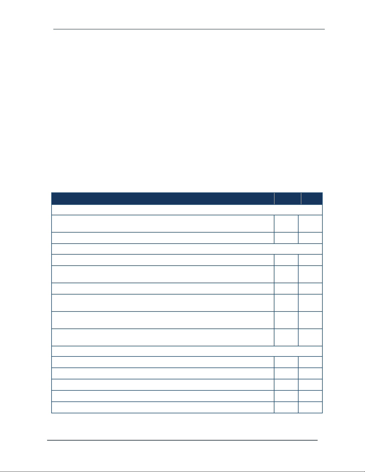
Checklist Question Yes No
Safety
Is the installation location room free of any equipment servicing hazards, such as electrical
or data cables that obstruct access?
Does the installation location have a fire-protection system?
Space Planning
Are there cutouts or channels to route cables?
Can the temperature be maintained between -20°C to 55°C (-4°F to 131°F) during
operations?
Can the humidity level be maintained between 0% and 90% non-condensing?
Is the installation location protected against dust, pollution, and metallic particulate
contamination?
Does the installation location take into account environmental considerations, such as
vibration and acoustics?
Is all equipment not supplied by Hardy Process Solutions (for example, power supply) on
site and ready for use?
Electrical Requirements
Is there a sufficient number of AC outlets for the equipment?
Are the AC outlets on different lines?
Are the input circuit breakers adequate for equipment loads?
Are uninterruptible power supplies (UPS) in place?
Have all sources of electrical interferences been addressed?
Hardy Process Solutions HI 6200 Weigh Processor User Guide 15
Page 16
Chapter 2 – Installation
2.3 Unpacking
The HI 6200 is shipped directly from Hardy Process Solutions.
1. Before signing the packing slip, inspect the packaging for damage, and report damage of
any kind to the carrier company.
2. Check that everything in the package matches the bill of lading.
3. If items are missing or you have any questions, contact Customer Service by phone, fax,
or email.
4. Record the model number and serial number of the HI 6200 series instrument. Store this
information in a convenient, secure location for reference when contacting Customer
Service, buying parts, or upgrading firmware.
A Return Material Authorization (RMA) number is required before returning any damaged
product. Use the website to request an RMA at https://www.hardysolutions.com/support-
center/repairs-form/view Have the following items ready:
Your Name, Company name, shipping address, email address and telephone number
Model Number & Serial number of the unit
Brief description of the problem
In case of damage due to shipping, notify the delivering carrier immediately for an
inspection.
WARNING: ELECTROSTATIC DISCHARGE MAY DAMAGE SEMICONDUCTOR
COMPONENTS IN THE INSTRUMENT. DO NOT TOUCH THE CONNECTOR
PINS.
AVERTISSEMENT: UNE DÉCHARGE ÉLECTROSTATIQUE PEUT
ENDOMMAGER DES COMPOSANTS SEMI-CONDUCTEURS DANS LE
INSTRUMENT. NE PAS TOUCHEZ LE CONNECTEUR.
WARNING: POWER DOWN THE SYSTEM BEFORE SERVICING THE
INSTRUMENT. DO NOT UNPLUG UNDER POWER.
AVERTISSEMENT: SYSTÈME D'ALIMENTATION AVANT D'ENTREVOIR LE
INSTRUMENT. NE PAS DÉBRANCHER SOUS LE POUVOIR.
Hardy Process Solutions HI 6200 Weigh Processor User Guide 16
Page 17

Chapter 2 – Installation
2.4 Climatization
An HI 6200 shipped or stored at extreme temperatures requires time to adjust to operating
temperatures before startup.
If the HI 6200 arrives in very hot or very cold weather, do not unpack it until it has been
allowed to reach room temperature (one to two hours).
Immediately exposing the HI 6200 to warm temperatures can cause condensation to occur,
which could damage the electronics.
If you notice any condensation, allow the HI 6200 to stand unattended for one to two hours,
and then unpack it.
2.5 Handling Precautions
Observe the following precautions when handling the HI 6200:
Wear an approved wrist-strap grounding device when handling the instrument.
Touch a grounded object or surface to rid yourself of any electrostatic discharged prior to
handling the instrument.
Handle the instrument from the bezel in front away from the connector. Never touch the
connector pins.
Do not install the instrument right next to an AC or high voltage DC module.
Route all the load voltage cables away from high voltage cables.
Hardy Process Solutions HI 6200 Weigh Processor User Guide 17
Page 18

Chapter 2 – Installation
2.5.1 Sources of Electrical Interference
Ensure that the HI 6200 is protected from sources of electrical interference. The following
table provides examples of electrical interference.
Potential Source Description
Wall outlets Power outlets for building maintenance and janitorial equipment, such as
vacuum cleaners and floor buffers, must be wired from circuit breakers on a
power panel separate from the computer system panel. The ground wires from
these outlets must connect to the normal building distribution panel and not to
the system ground. If a separate power source and separate ground are not
provided, maintenance and janitorial equipment can induce electrical noise
that can affect operation of the HI 6200. Your electrician can verify whether
maintenance outlets are on separate panels.
Lightning In geographical areas subject to lightning storms, you may want install
lightning protection for your HI 6200. The principles of lightning protection and
personnel safety are described in the National Fire Protection Association
(NFPA) Handbook.
Electromagnetic interference Electromagnetic interference can cause various problems. The HI 6200 is
designed to reduce its susceptibility to radiated and conducted interference. A
Hardy Process Solutions representative can advise you about common
causes of electromagnetic interference.
Hardy Process Solutions HI 6200 Weigh Processor User Guide 18
Page 19
Chapter 2 – Installation
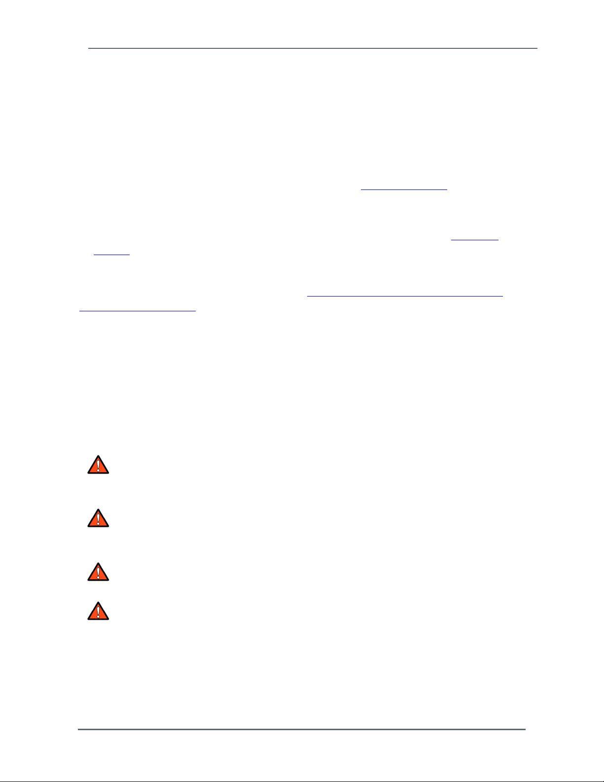
2.6 Mounting the HI 6200
The HI 6200 is designed for mounting on a 35mm DIN rail using the spring-loaded DIN clip
integrated into the body of the instrument.
Figure 2-1. DIN Rail Clips
To mount the HI 6200:
1. Engage the bottom of the DIN rail.
Hardy Process Solutions HI 6200 Weigh Processor User Guide 19
Page 20
Chapter 2 – Installation
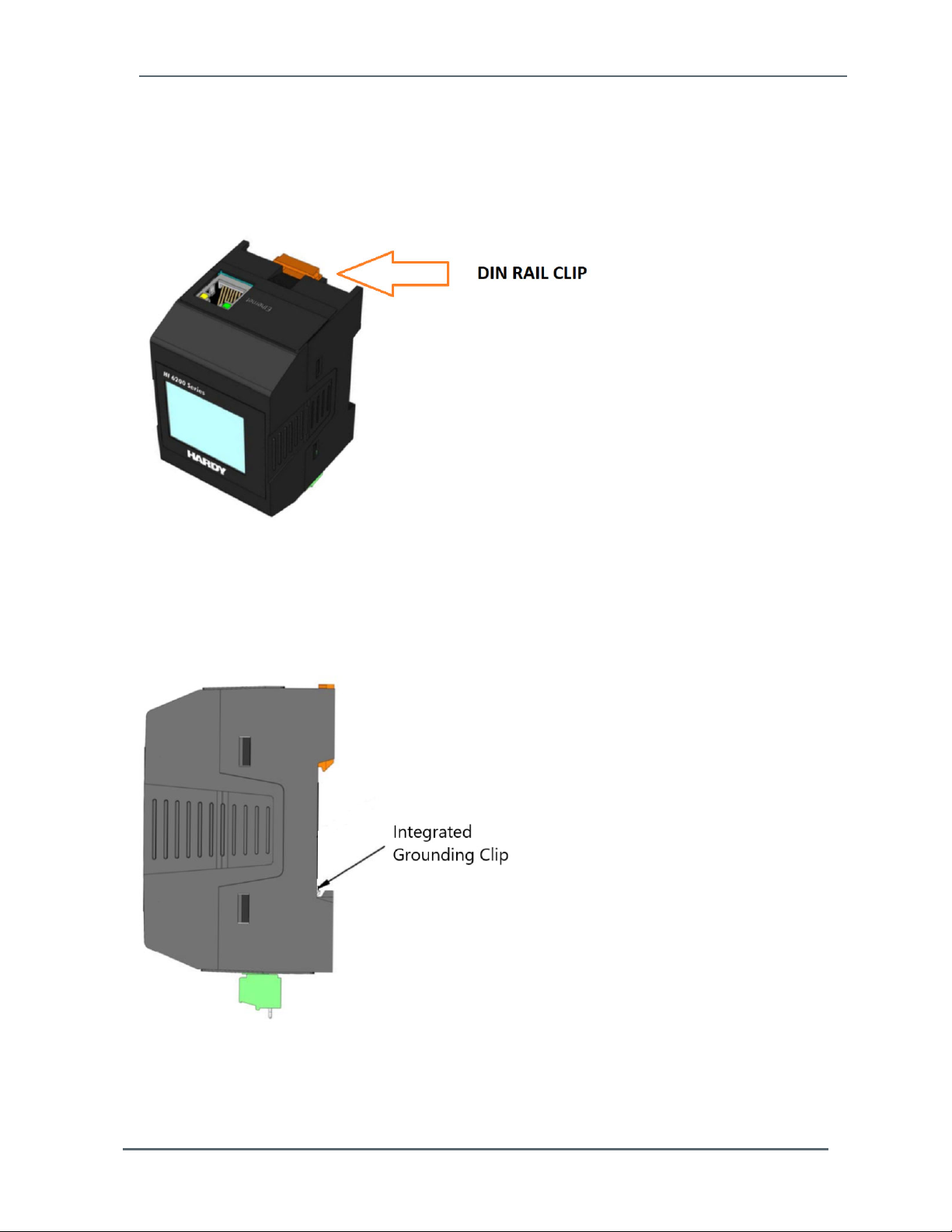
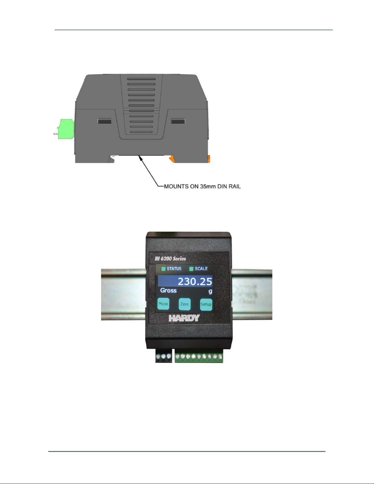
2. Snap the top of the HI 6200 onto a DIN rail.
Figure 2-2. Mounts on the DIN Rail (Horizontal Mounting)
Figure 2-3. Mounts on the DIN Rail (Vertical Mounting)
To remove the HI 6200:
1. Locate the slot on the top of DIN rail clip.
2. Gently pry up until the instrument releases.
Hardy Process Solutions HI 6200 Weigh Processor User Guide 20
Page 21
Chapter 2 – Installation
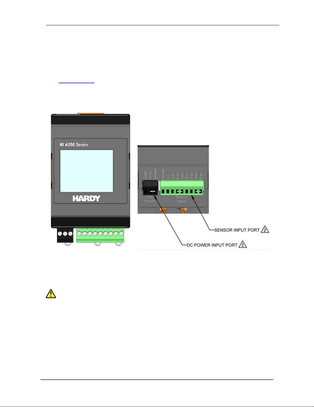
2.7 Wiring the HI 6200
The HI 6200 has screw-down terminal blocks for power and load cell connections, and an
RJ-45 jack on the top for Ethernet communications. For detailed information about wiring
terminations, refer to the installation and interconnection diagram in document #0584-0107
on the Hardy website.
When tightening wiring onto the screw-down terminal blocks, remove the terminal blocks
from the instrument to prevent undue stress on the instrument.
Figure 2-4. HI 6200 Wire Terminations to Hardy Sensors and Junction Boxes
Caution: Do not over-tighten the screw-down terminal blocks. Otherwise, you
might shear sensor wires and cause intermittent or complete failure of the
weighing system.
Hardy Process Solutions HI 6200 Weigh Processor User Guide 21
Page 22
Chapter 2 – Installation
Observe the following wiring best practices:
If conduit is used, do not run load cell cable parallel to, or in the same conduit with, power
wiring, relay cable, or other high-energy cables.
If you connect four wire load sensors with C2 and four wire load sensors without C2
directly to the termination base assembly, install wire jumpers in the termination base
assembly where indicated.
Required load cell cable for C2 electronic calibration system and INTEGRATED
TECHNICIAN is Hardy Process Solutions part number C2Cable (6020-0001-0).
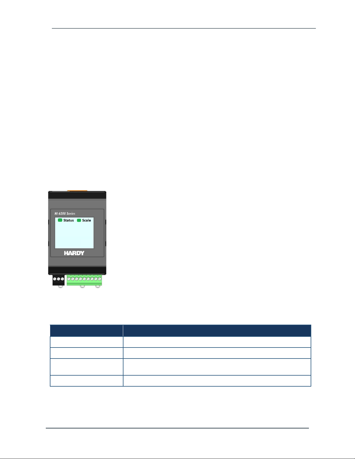
2.8 Powering on the HI 6200
After wiring the HI 6200, power on the instrument and check that Status and Scale LEDs on
the front panel indicate normal operation. Press Status Light for additional detail on
condition.
Figure 2-5. Status and Scale LEDs
Table 2-1. LEDs
LED Color and Status Description
Steady Green Instrument is operating normally.
Flashing green Error, no calibration. Press the on-screen Status button for more information.
Steady red Read failure or EEPROM write error. Press the on-screen Status button for
Flashing red Read convert error. Press the on-screen Status button for more information.
Hardy Process Solutions HI 6200 Weigh Processor User Guide 22
more information.
Page 23

3 INITIAL SETUP
Topics:
Initial Setup (page 24)
This chapter describes how to set up the
HI 6200 prior to initial use.
Hardy Process Solutions HI 6200 Weigh Processor User Guide 23
Page 24

Chapter 3 – Initial Setup
3.1 Initial Setup
The following steps describe the minimum configuration procedures to perform when setting
up the HI 6200 for the first time. Perform these procedures in the order shown.
For detailed descriptions of scale parameters and how to use them when setting up a scale
system, see Chapter 5.
1. Choose a calibration method: C2 OR Hard Cal (not both).
Recommended Method: Perform C2 – Electronic Calibration:
a. Remove all live weight from the scale. Leave all dead load weight, like vessels,
mixers, etc. on the scale.
b. Press Do C2 Cal.
c. Place a verification weight on the scale to ensure the weight reading matches and that
calibration is successful.
Alternate Method: Perform Hard Cal- Traditional
a. Traditional Calibration requires a zero point and the physical placement of test weights
on the scale. To set the Zero Value, if all “live load” weight is removed from the Scale,
the Zero Value should be 0.00. If any weight is on the scale when setting this value,
the weight must be equal to the amount of load on the scale.
b. Wait 12 seconds or more.
c. Click in the Ref Weight text field and enter the reference weight you want. In our
example, we entered 0 lbs. If you want the reference weight to be 5.0 lbs., enter 5.0.
d. Click the Do Cal Low button to do the Trad Cal Zero. A “Cal Completed OK” message
appears briefly if the calibration was successful. An Error number appears if the
calibration was not successful. See the Error list in Chapter 8 for help in correcting the
error.
e. To set the Span Weight, place a certified test weight on the scale.
f. In the Span Weight text field, enter the amount of live load weight placed on the scale.
g. Click the Do Cal High button. A “Cal Completed OK” message appears briefly if the
calibration was successful.
h. An Error message appears if the calibration was not successful. See the error list in
Chapter 8, for help in correcting errors.
i. Step 9. The scale is now calibrated
Hardy Process Solutions HI 6200 Weigh Processor User Guide 24
Page 25

Chapter 3 – Initial Setup
Multi-Point Calibration
Multi‐PointCalibration,(alsocalledmidpointcorrection)issimplyacalibrationwith3‐5points.
Standardtwo‐pointcalibrationassumeslinearity(astraightline).However,calibrationtojust2end
pointsmaynotaccommodatefornon‐linearity(acurvedline)thatmayhappeninthemiddleofthe
loadcurve.
Multi‐Pointcalibrationletsuserscalibrateatthree,fourorfivevaluesonthecurve.Amulti‐point
calibrationmeans,incomparisontoatwo‐pointcalibration,thatyoucancalibratenon‐linearity
significantlymoreaccurately
Toachievethebestpossibleaccuracy,themulti‐pointcalibrationshouldcovertheentirerangeof
thedesiredmeasurementvalues(fromzerotothehighestpossiblevalue).
ToaccessMulti‐PointCalibrationfromthewebbrowser,clickontheMulti‐PointCalibrationlinkat
thebottomoftheCalibrationpage.
a. First, select the number of Cal Points necessary to accommodate for non-linearity
that can’t be mechanically corrected in the system. Users that have previously
performed a Calibration or set the span weight value using traditional calibration, will
see that value populated as the highest number of Cal Points selected (for example,
point 3-5 depending on your instrument.).
b. Perform each calibration step by step from Cal Point 1 to the next point Weight (e.g.
Cal Point 2 then Cal Point 3) until you reach your last selected point
c. The system will be calibrated with multiple points, providing the most accurate
method for a non-linear calibration.
Note: Multi-Point Calibration is only available through the Webserver, not the panel display.
Hardy Process Solutions HI 6200 Weigh Processor User Guide 25
Page 26

4 WAYS TO SET SCALE
PARAMETERS
Topics:
Using the Touch Screen (page 27)
Using the Embedded Webserver
(page 29)
Using a PLC (page 36)
For convenience, the HI 6200 Weight
Processor provides the following ways to set
scale parameters:
Front panel touch screen provides access
to all instru
Embedded Webserver provides access to
ment settings and parameters.
the touch screen settings along with
advanced diagnostics, parameter cloning,
and firmware upgrade parameters.
PLC provides PLC communications (EIP
or Modbus).
Hardy Process Solutions HI 6200 Weigh Processor User Guide 26
Page 27

Chapter 4 – Ways to Set Scale Parameters
4.1 Using the Touch Screen
To set up the HI 6200 using its front panel touch screen:
1.
At the lower right side of the screen, press the Setup button to access the Setup me
2.
From the Set-up area, press the left or right arrow key to scroll through the main me
Press the top selection or the OK button to access the secondary menus.
3.
nus.
nus.
Press the left or right arrow key to scroll through the secondary menus.
4.
5.
To make a selection, press a secondary menu item or the OK
To return to the previous menu, press the Back
6.
To return to the home screen, press the Home button.
7.
Hardy Process Solutions HI 6200 Weigh Processor User Guide 27
button.
button.
Page 28

Chapter 4 – Ways to Set Scale Parameters
Table 4-1 shows the organization of the touch screen menus.
Table 4-1. Touch Screen Menus
Home Zero Command
Tare Comman d
Mode Net
Set‐U p Calib ration C2 Gravity UserInputvariable
Gross
RefWeight UserInputvariable
DoC2 Comma nd
NumDevices DeviceInfo
HardCal CalLo wWeight UserInputvariable
DoCalLo w Comman d
SpanWeight UserInputvariable
DoCalHigh Comma nd
CalDate UserInputvariable
Communication EtherNetTCP/IP Ena bleDHCP On
Off
FixedIP UserInputvariable
DynamicIP U serI nputvariable
MaskAddress UserInputvariable
GatewayAddress UserInputvariable
DNSServer Use rInputvariable
EtherNetUDP HardyPort UserInputvariable
ModbusTCP Status DeviceInfo
EtherNet/IP Status DeviceInfo
ProfiNet reserve
Filter Filter Fast
Balanced
Stable
Custom
Off
Operations AutoZero Auto Zero Enable
Disable
Tolerance UserInputvariable
TareOps TareWeight UserInputvariable
ZeroOps ZeroTolerance UserInputvariable
Zero
Setting s DecimalPt. UserInputvariable
Capacity UserInputvariable
Grads 1
2
5
10
100
InstrumentID UserInputvariable
Motio nTo lera nce U serI nputvariable
OperatorID UserInputvariable
Units oz
lb
ton
g
kg
mt
Security None checkmark
Medium checkmark
High checkmark
Password UserI nputvariable
Info FWVersion informationonly
Produc tSN informationonly
HWrev. informationonly
Hardy Process Solutions HI 6200 Weigh Processor User Guide 28
Page 29

Chapter 4 – Ways to Set Scale Parameters
4.2 Using the Embedded Webserver
The embedded Webserver is a graphical point-and-click interface that can be accessed
using a computer that has an Internet connection. Using the embedded Webserver, you can
access the same instrument settings and parameters available from the front panel touch
screen plus the following additional features:
Advanced diagnostics
Parameter cloning
Firmware upgrade
To set up th
If the HI 6200 is powered on, power it off.
1.
2.
Connect either end of a straight-through or crossover Ethernet cable to t
connector o
e HI 6200 using its
n the top of the HI 6200. Connect the other end of the cable to
embedded Webserver:
he RJ-45
a Network
Switch or Router.
3.
Power up the HI 6200. The instrument automatically negotiates setting
variety of op
Wait approximately 15 seconds, and then check whether the green light o
4.
port is blin
can skip
erating systems and network config
king. If it is blinking, the computer can communica
to step 5. Otherwise, perform the following steps:
urations.
te with the HI 6200 and you
s suitable for a
f the Ethernet
a. The HI 6200’s default static IP address is 192.168.0.100. To communicate with the
instrument, configure th
octets in the
octet) is a n
IP address) are the same as the HI 6200 and the node ident
umber from 0 to 255 other than 100. For example: 192.168.0.
e computer’s IP address so the network
identifier (first three
ifier (last
101.
Hardy Process Solutions HI 6200 Weigh Processor User Guide 29
Page 30

Chapter 4 – Ways to Set Scale Parameters
b. On your computer, right-click the Local Area Connection icon of the network adapter,
and then cli
ck Properties
.
In the Networking tab, check Internet Protocol Version 4 (TCP/IPv4), and then cli
c.
Properties.
Check Internet Protocol
Version 4 (TCP/IPv4).
Click Properties.
ck
d.
In the General tab, select Use the following IP address, and then enter the followin
values:
IP address = 192.168.0.101
Subnet mask = 255.255.255.000
Complete the IP address
and Subnet mask fields.
Click OK.
g
Hardy Process Solutions HI 6200 Weigh Processor User Guide 30
Page 31

Chapter 4 – Ways to Set Scale Parameters
e. Click OK in the TCP/IP Properties dialog box.
f. To return the computer to the original network settings, return to the Inter
(TCP/IP) dialog, sele
Open a web browser on the computer, enter the static IP address of the
5.
instrument (192.168.000
ct check Obtain an IP address automatically, and click OK
.100), and press the Enter key. The Home page appears (see
Figure 4-1).
net Properties
.
HI 6200
Figure 4-1. Embedded W
ebserver Home Page
Hardy Process Solutions HI 6200 Weigh Processor User Guide 31
Page 32

Chapter 4 – Ways to Set Scale Parameters
4.2.1 Saving “Known Good” Parameters
You can save the HI 6200 configuration to a different location in memory in order to restore
the configuration if it becomes compromised.
1.
Open a web browser on the computer, enter the static IP address of the
instrument that you set in a previous step (for example: the factory default is
192.168.000
page 31).
2.
Click Configuration, and then click Diagnostics.
3. Click Parameters
.100), and press the Enter key. The Home page appears (see Figure 4-1
.
HI 6200
on
Hardy Process Solutions HI 6200 Weigh Processor User Guide 32
Page 33

Chapter 4 – Ways to Set Scale Parameters
4. Make sure all the parameter values are set to your requirements.
5.
Click the Save As KnownGood bu
tton.
Hardy Process Solutions HI 6200 Weigh Processor User Guide 33
Page 34

Chapter 4 – Ways to Set Scale Parameters
4.2.2 Restoring from “KnownGood” Parameters
After you use the procedure in section 4.2.1 to save a last-known good configuration, you
can restore the HI 6200 to that configuration if necessary.
1.
Open a web browser on the computer, enter the static IP address of the
instrument (192.168.000
Figure 4-1 on
2.
Click Configuration, and then click Diagnostics
3.
Click Parameters
page 31).
.
.100), and press the Enter key. The Home page appears (see
.
HI 6200
4.
Click Known Good Cfg
Hardy Process Solutions HI 6200 Weigh Processor User Guide 34
.
Page 35

Chapter 4 – Ways to Set Scale Parameters
5. Click the Restore KnownGood button.
Hardy Process Solutions HI 6200 Weigh Processor User Guide 35
Page 36

Chapter 4 – Ways to Set Scale Parameters
4.3 Using a PLC
4.3.1 EIP
Many of the set-up procedures in this section require an EIP system. In this section, the
Allen Bradley system is used.
Note: The HI 6200 is not
Make sure the HI 6200 is installed with the HI 6020IT, HI 6020JB, HI 6010IT or HI
6010JB Junction Boxes. It is compatible with the HI 215JB without the IT functions.
compatible with the obsolete HI 215IT Junction Boxes.
4.3.2 Setting Up Communications
The following procedure describes how to set up communications between the ControlLogix
PLC and the HI 6200. This procedure requires a new or open RS Logix® 5000 project. For
instructions, see your RS LOGIX 5000 manual.
For this setup example/instructions, use the
download from the Hardy website. For information about how to install EDS files, see the
Rockwell instructions.
1.
In the program Controller Organizer, find the I/O Configuration section.
2.
Right-click the Ethernet Module under which you will be installing the HI6200-WS module.
Select New Module to display a list
3.
From the catalog list, select the Hi6200 Series EDS_AOP modu
4.
EDS_AOP file. This file is available as a free
of modules.
le.
Hardy Process Solutions HI 6200 Weigh Processor User Guide 36
Page 37

Chapter 4 – Ways to Set Scale Parameters
5. Configure the module by entering a unique name and entering the instrument’s IP
address.
Enter a
unique
name.
Enter the
instrument’s
IP address.
In the Connection tab, make sure the Requested Packet Interval (RPI) is set to 10ms
6.
.
Hardy Process Solutions HI 6200 Weigh Processor User Guide 37
Page 38

Chapter 4 – Ways to Set Scale Parameters
7. Click OK. The module appears in the controller organizer in the I/O configuration under
the Ethernet section.
8.
Repeat this procedure fo
r any additional modules.
4.3.3 Configuration Parameters
Table 4-2 lists the parameters used when configuring the IO. (See an explanation of
Parameters in Chapter 5.)
Table 4-2. IO Parameters
Configuration Parameters Data Type
Enable/Disable Configuration INT
Decimal Point SINT
Grads SINT
Unit SINT
WAVERSAVER SINT
Num Averages INT
Loadcell Sensitivity INT
AutoZero INT
AutoZero Tolerance FLOAT
Gravity Correction FLOAT
Motion Tolerance FLOAT
Zero Tolerance FLOAT
Tare Weight FLOAT
Reference Weight FLOAT
Span Weight FLOAT
Scale Capacity FLOAT
Hardy Process Solutions HI 6200 Weigh Processor User Guide 38
Page 39

Chapter 4 – Ways to Set Scale Parameters
4.3.4 Configuration with AOP
Using the EDS_AOP file makes configuring the HI 6200 instrument fast and easy.
Note: If the configuratio
n is “enabled” in the AOP or configuration table, the
configuration table downloads into the instrument every time the connection is
established.
Open the
1.
To use the configuration parameters, set the parameter Enabl
2.
Table to Enable. Otherwise any changes done
Properties of the Module and go to the Configuration section.
e/Disable Configuration
through the configuration tab will not
applied to the instrument.
Make any required chan
3.
Click Apply. The configuration table is downloaded to the instrument. The
4.
then uses th
e information in the table to set parameters automa
ges.
tically.
be
instrument
4.3.5 PLC Commands
The PLC can control the HI 6200 using the commands in Table 4-3. The sections following
the table provide detailed descriptions about the commands.
Table 4-3. Hardy Commands
Command Number Command
(0x00)0 Read Parameter
(0x01)1 Zero Cmd
(0x02)2 Tare Cmd
(0x64) 100 dec Cal Low Cmd
(0x65) 101 dec Cal High Cmd
(0x66) 102 dec C2 Cal Cmd
(0x80) 128 dec IT Test
Hardy Process Solutions HI 6200 Weigh Processor User Guide 39
Page 40

Chapter 4 – Ways to Set Scale Parameters
Command Number Command
(0x81) 129 dec Stability Test
(0x82) 130 dec IT Test (Reduced Voltage)
(0x83) 131 dec C2 Search
(0x92) 146 dec Write INT Value Command (e.g., number of averages to 50)
(0x93) 147 dec Write FLOAT Value Command (e.g., motion tolerance to 1.5)
(0x94) 148 dec Set Default Parameters (all parameters except IP addresses)
(0x95) 149 dec Set Default Network Parameters (IP addresses only)
(0x97) 151 dec Save Last Good Configuration to Non-volatile Memory
(0x98) 152 dec Restore Last Good Configuration from Non-volatile Memory
READ PARAM CMD
Hex value: 0x00
Decimal value: 0
To read a parameter, write the hexadecimal value 0x00 to the CMD register (register #0),
and write the parameter number in the
parameter value may then be read from the
ParameterID register of the output table. The
ParameterValue register in the input table.
This value can be in integer or floating-point format, depending on the parameter. The
Command status register in the reply contains the lower 16 bits of the system Command
status word.
Status word bit 0: A/D error
Status word bit 7 (0x80): Not Found - the requested parameter number does not exist
Status word bit 6 (0x40): Motion status
ZERO CMD
Hex value: 0x01
Decimal value: 1
Write the hexadecimal value 0x01 to the command register to zero the gross weight. If this
command succeeds, the status register reads 0.
Status Error code 1 Fail
Status Error code 2 ADC Failure
Status Error code 3 Out of tolerance
Status Error code 4 Motion
Status code FF cmd in progress
Hardy Process Solutions HI 6200 Weigh Processor User Guide 40
Page 41

Chapter 4 – Ways to Set Scale Parameters
TARE CMD
Hex value: 0x02
Decimal value: 2
Performing a tare command changes the net weight to “0” and moves the tared value into
the “tare weight” parameter. Write the hexadecimal value 0x02 to the command register to
zero the net weight. If this command succeeds, the Cmd Status (lower 8 bits of
CmdStatusNCount) reads 0.
Status Error code 1 Fail
Status Error code 2 ADC Failure
Status Error code 4 Motion
Status code FF cmd in progress
CAL LOW CMD
Hex value: 0x64
Decimal value: 100
Write the hexadecimal value 0x64 to the command register to perform the low step of a
traditional calibration. If this command succeeds, the status register reads 0.
Status Error code 1 Fail
Status Error code 2 ADC Failure
Status Error code 4 Motion
Status code FF cmd in progress
CAL HIGH CMD
Hex value: 0x65
Decimal value: 101
Write the hexadecimal value 0x65 to the command register to perform the high step of a
traditional calibration.
Status Error code 1 Fail
Status Error code 2 ADC Failure
Status Error code 4 Motion
Hardy Process Solutions HI 6200 Weigh Processor User Guide 41
Page 42

Chapter 4 – Ways to Set Scale Parameters
HardcalFailCounts 8 Insufficient number of counts between hard cal hi and hard cal lo
Status code FF cmd in progress
C2 CAL CMD
Hex value: 0x66
Decimal value: 102
Write the hexadecimal value 0x66 to the command register to perform a C2 calibration.
Status Error code 1 Fail
Status Error code 2 ADC Failure
Status Error code 4 Motion
Status Error code 5 no C2 cells
Status Error code 6 C2 capacities not equal
Status Error code 7 Non-Hardy C2 load sensor
Status code FF cmd in progress
IT Test
Hex value: 0x80
Decimal value: 128
Write the hexadecimal value 0x80 to the command register to perform an Integrated
Technician test. This test requires an IT summing card.
Status Error code 1 Fail or no IT Summing Card Found
Status code FF cmd in progress
Stability Test
Hex value: 0x81
Decimal value: 129
Write the hexadecimal value 0x81 to the command register to perform the stability test.
Status Error code 1 Fail
Status code FF cmd in progress
Hardy Process Solutions HI 6200 Weigh Processor User Guide 42
Page 43

Chapter 4 – Ways to Set Scale Parameters
IT Test Reduced
Hex value: 0x82
Decimal value: 130
Write the hexadecimal value 0x82 to the command register to perform an Integrated
Technician test with reduced voltage. This test requires an IT summing card.
Status Error code 1 Fail or No IT Summing Card Found
Status code FF cmd in progress
C2 Search
Hex value: 0x83
Decimal value: 131
Write the hexadecimal value 0x83 to the command register to force the module to search for
and read/update C2 data.
Status Error code 1 Fail
Status code FF cmd in progress
WRITE CMD
Hex value: 0x92
Decimal value: 146
Set the value of a parameter. Write the hexadecimal value 0x92 in the command register 0,
the parameter ID number in the
ParameterValue register of the output table.
Status Error code 1 Fail
Status Error code 0x0B Value out of range too high
Status Error code 0x0C Value out of range too low
Status Error code 0x0D Not allowed
Status Error code 0x80 Invalid parameter ID
ParameterID register, and the desired value in the
Hardy Process Solutions HI 6200 Weigh Processor User Guide 43
Page 44

Chapter 4 – Ways to Set Scale Parameters
Set Default Parameters
Hex value: 0x94
Decimal value: 148
Write the hexadecimal value 0x94 to the command register to set all parameters and
calibration back to default settings.
Status Error code 1 Fail
Set Default Network Parameters
Hex value: 0x95
Write to NVM (non-volatile memory)
Hex value: 0x96
Save Last Good Configuration
Hex value: 0x97
Table 4-4. Instrument Status Word Bits
Bit Description
0 A/D converter error - bad input from the load sensor.
1 A/D converter failure - no output from the converter to the processor.
2 Motion - indicates weight is in motion (changing).
3 Center of Zero
6 Calibration in Progress
7 Error parameter ID Not Found
Table 4-5. Command Status Return Value
Return Value Description
0 Success
1 Fail
2 Fail - ADC error and ADC failure
3 Fail - out of tolerance
4 Fail - motion
5 Fail - no C2 load cells found
Hardy Process Solutions HI 6200 Weigh Processor User Guide 44
Page 45

Chapter 4 – Ways to Set Scale Parameters
Return Value Description
6 Fail - C2 capacities not equal
7 Fail - non-Hardy C2 load sensor
8 Fail - not enough counts between Cal low and Cal high weights
11 Fail – param value too high
12 Fail – param value too low
13 Fail – not allowed
128 Fail – Parameter ID not found
4.3.6 Modbus
Modbus is an application-layer messaging protocol that supports client/server
communications between devices connected on different types of buses or networks. All
HI 6200 series units have Modbus TCP built-in. To have the instrument communicate
through Modbus-TCP, use the touch screen or web browser to configure the HI 6200 for
Modbus TCP.
If you do not have a Modbus PLC available to test the Modbus communications, download
the Hardy Modbus-Link client software from the Hardy website to test communications with
the HI 6200 instrument. The package communicates with the HI 6200 only and is not a full
communications package. If you encounter problems with this test, contact Hardy Customer
Service.
Modbus services are specified by function codes that are elements of MODBUS
request/reply PDUs. MODBUS is implemented for the HI 6200 using TCP/IP over Ethernet.
In this client/server configuration, the client is the module requesting data and the server is
the module providing the data.
Note: MODBUS is locat
ed at level 7 of the OSI model and accessed at a reserved
system port 502 on the TCP/IP stack. It supports communication with up to 10
different hosts (sockets).
4.3.6.1 Configuring MODBUS
1. Download the Hardy Modbus-Link client software:
Hardy Process Solutions HI 6200 Weigh Processor User Guide 45
Page 46

Chapter 4 – Ways to Set Scale Parameters
a. Open a web browser on your computer.
b. Go to the Hardy website: http://www.hardysolutions.com
c. Click the Support Center link, hover over Doc & Program Downloads, and click
HI 4000 Series Support Page. Then download the client
sof
tware from the HI 4050
Weight Controller page.
After downloading the client software, double-click the
2.
install th
Link icon ap
3.
Double-click the Hardy Modbus-Link icon to open the Hardy Modbus-Lin
e software on your computer. When the installation completes, a Hardy Modbus-
pears on your Desktop.
Hardy Modbus-Link .exe
Figure 4-2).
file to
k display (see
Figure 4-2.
From the Connection menu, click Connect. The TCP/IP Connection dialog box appears.
4.
Hardy Process Solutions HI 6200 Weigh Processor User Guide 46
Hardy Modbus-Link Display
Page 47

Chapter 4 – Ways to Set Scale Parameters
5. If TCP/IP is not selected in the top-right field, select it from the pull-down list.
6.
In the IP Address field at the bottom right, type the address of the HI 6200 inst
with which you want to communicate
7.
Click OK. The red No Connection message disappears and the values at the top of
page chang
e. Your computer is now connected to
.
Select TCP/IP.
Type the address of the HI 6200 instrument.
the HI 6200.
rument
the
Hardy Process Solutions HI 6200 Weigh Processor User Guide 47
Page 48

Chapter 4 – Ways to Set Scale Parameters
8. From the Setup menu, click Poll Definition. In the Poll definition dialog box, select the
following set
Function = 04 INPUT REGISTER
–
tings, and then click OK
:
Address =
–
0
– Length = 10
9.
On the Hardy Modbus-Link page, from the Display menu, click Float. The
appears in r
aware of random numbe
egister 6 (net) or register 8 (gross). Other registers are not floa
rs in other registers.
Weight value
t values, so be
Hardy Process Solutions HI 6200 Weigh Processor User Guide 48
Page 49

Chapter 4 – Ways to Set Scale Parameters
10. From the Display menu, click Long. This allows you to write an integer value into the
non-float registers.
11.
From the Functions menu, select Read/Write Registers
OR
Click button 23 to open the Write multiple registers dialog box
:
12. Double-click the top register. When the Enter Value box appears, enter the new value
you want to
the Tare co
write to this register. The following figure shows writing a value of 2
mmand nu
mber.
, which is
Hardy Process Solutions HI 6200 Weigh Processor User Guide 49
Page 50

Chapter 4 – Ways to Set Scale Parameters
13. Click OK to accept the value, and then click the Send button to send the values to the HI
6200.
14. When the Response OK message appears, click OK
Change the display back to Float and confirm that the Tare command cha
15.
.
nged the Net
weight to zero.
4.3.6.2 I/O Tables for Communications to PLC
Table 4-6 and Table 4-7 on page 51 are common for the EtherNet/IP and Modbus – TCP
communication protocols.
Table 4-6. Output Table
Output Table Type
Command INT
Aux Command Information INT
Parameter Value DINT
Parameter ID INT
Reserved 1 INT
Reserved 2 INT
Reserved 3 INT
Reserved 4 INT
Reserved 5 INT
Total 10
Command, Aux Command Information, Parameter ID, and Parameter Value are used
to send commands to the instrument, write new parameter values, read existing parameter
Hardy Process Solutions HI 6200 Weigh Processor User Guide 50
Page 51

Chapter 4 – Ways to Set Scale Parameters
values, and read data values. The command is a 16-bit value used for the command string,
as shown above in the command section.
The 16-bit
Aux Command Information is used for specific information required for special
commands. The parameter ID register is used to select the parameter to read/write. The
Parameter Value is used to set the new value for a write. This register is ignored if doing a
read.
The following values are reserved to provide padding, so the user-selectable read-only
parameters are aligned between the output and input tables:
Reserved 1 Reserved 4
Reserved 2 Reserved 5
Reserved 3
Table 4-7. Input Table
Input Table Type
Command Echo INT
Command Status and Sample Counts INT
Parameter Value DINT
Parameter ID INT
Instrument Status INT
Net Weight REAL
Gross Weight REAL
Total 10
The first fou
r variables in the input table in Table 4-7
Command Echo, Command Status,
Parameter ID, and Parameter Value match closely the first four variables in the
output table in Table 4-6.
Command Echo echoes the command from the output table. This allows the user to ensure
that the correct command has been executed and that the command status value is valid.
Command Status and Sample Counts returns the command status of the command being
run and the Counts from 0 – 255 repeat. The value returned in the lower byte of the register
is the status code for the command. This code is one of the following values:
Hardy Process Solutions HI 6200 Weigh Processor User Guide 51
Page 52

Chapter 4 – Ways to Set Scale Parameters
A zero indicating the command passed.
A value of 0xFF indicating the command is in process.
An error code indicating the reason the command failed (see Table 4-5).
The upper 8 bits of the r
egister are a cyclic “measurement update count,” which increment
by 1 (one) each time a new measurement value is taken, following a 0 to 255 then repeat
cycle. If this value remains the same in two consecutive reads from the instrument, the
communication or the measurement function has failed and appropriate action must be
taken.
Parameter ID is an echo of the value sent in the output table. Parameter Value is the
current value for the specified Parameter ID. This parameter value may ether be an integer
or in floating point format depending on which Parameter ID is specified.
Instrument Status is a 16-bit value that provides the current state of all the major
functions within the instrument. They reflect the status of all the major functions and should
be used with the “measurement update count” to determine the health of the instrument.
Net Weight and Gross Weight values are always provided.
The
4.3.6.3 Default Parameter Values
Table 4-8 shows the default parameters values.
Table 4-8. Default Parameters Values
Configuration Table Data Type Default Range Values
Gravity Correction FLOAT 1.0 0.9-1.1
Decimal Point BYTE 2 0-5
Grad Size
BYTE
Motion Tolerance FLOAT 10.0 .00001-999999.99
Zero Tolerance FLOAT 10.0 .00001-999999.99
Tare Weight FLOAT 0.0
Reference Weight FLOAT 0.0 .00001-999999.99
Scale Cap FLOAT 999999.0 .00001-999999.99
Span Weight FLOAT 1000.0 .00001-999999.99
0 0-9 0 = 1
1 = 2
2 = 5
3 = 10
4 = 20
5 = 50
6 = 100
7 = 200
8 = 500
9 = 1000
Hardy Process Solutions HI 6200 Weigh Processor User Guide 52
Page 53

Chapter 4 – Ways to Set Scale Parameters
Configuration Table Data Type Default Range Values
AutoZero Tolerance FLOAT 10.0 0 -999999.99
Enable AutoZero Tracking
Unit
Load Cell Sensitivity
Waversaver
BYTE
BYTE
BYTE
BYTE
0 0-1 0 = off
1 = on
1 0-5 0 = oz
1 = lb
2 = ton
3 = g
4 = kg
5 = t
4 0-8 0 = 1.0 mV/V
1 = 1.5 mV/V
2 = 2.0 mV/V
3 = 2.5 mV/V
4 = 3.0 mV/V
5 = 3.5 mV/V
6 = 4.0 mV/V
7 = 4.5 mV/V
8 = 5.0 mV/V
3 0-5 0 = Off
1 = 7Hz
2 = 3.5 Hz
3 = 1Hz
4 = 0.5Hz
5 = 0.25Hz
Num Averages INT 10 1-255
Hardy Process Solutions HI 6200 Weigh Processor User Guide 53
Page 54

5 SETTING SCALE PARAMETERS
Topics:
Pre-Calibration Procedures
(page 55)
Calibration Setup Procedures
(page 56)
Calibrating the Scale (page
60)
This chapter provides the recommended calibration
procedure for the HI 6200 Weight Processor. For
the instrument to work properly, it must be
calibrated prior to operation, and then verified
periodically or when not in use for extended periods
of time. We recommend a scale verification rather
than a calibration. Be sure to follow all the
procedures completely to ensure that the weights
read by the instrument are accurate.
Hardy Process Solutions HI 6200 Weigh Processor User Guide 54
Page 55

Chapter 5 – Setting Scale Parameters
5.1 Pre-Calibration Procedures
1. Determine whether the load sensors are installed properly. See your load sensor’s
installation manual for proper installation instructions.
2. A down arrow on some sensors and cells shows the correct direction of the applied load.
If the arrow points in the wrong direction, reposition the load sensor so the arrows face
down.
3. Check for binding on the load sensor, mount, or other parts of the weighing system.
WARNING: BINDING ON A SCALE/VESSEL OR LOAD CELL DOES NOT
ALLOW THE LOAD SENSOR FREE VERTICAL MOVEMENT AND MAY
PREVENT THE INSTRUMENT FROM RETURNING TO THE ORIGINAL ZERO
REFERENCE.
AVERTISSEMENT: LIER SUR UNE ÉCHELLE / RÉCIPIENT OU CELLULE DE
CHARGE NE PERMET PAS LA CELLULE DE CHARGE LIBRE CIRCULATION
VERTICALE ET PEUT EMPÊCHER L'APPAREIL DE REVENIR AU POINT DE
RÉFÉRENCE ZÉRO D'ORIGINE.
4. Load sensors must be mounted so that 100% of the load (Vessel w/Contents) passes
vertically through all the sensors comprising the system. Verify that nothing is binding the
load sensors. This means that nothing is draped across the scale/vessel or the load
sensor, such as a hose, electrical cord, tubes, or other objects.
5. Verify that nothing is in contact with the scale/vessel other than service wires and piping
that have been properly mounted with flexible connections. Flexible pipes are not to be
used in any other than the horizontal plane and are not to be used to correct pipe
alignment problems. Vertical or at angles other than horizontal will have a negative effect
on the scale’s ability to repeat and provide accurate weight readings.
Hardy Process Solutions HI 6200 Weigh Processor User Guide 55
Page 56

Chapter 5 – Setting Scale Parameters
5.2 Calibration Setup Procedures
5.2.1 Unit of Measure
The unit of measure can be set to ounces, pounds, tons, grams, kilograms, or metric tons.
Any weight value input to the module (for example, REFERENCE WEIGHT, SPANWEIGHT)
is in the currently selected units. The unit of measure can be set at any time, not just at
calibration. Setting the unit of measure before calibrating reminds you what unit of measure
is being displayed.
Note: The weigh scale module does not need to be calibrated again after
changing the unit of measure.
5.2.2 Motion Tolerance
Motion Tolerance defines the amount the weight reading needs to change in a 1 second
period of time to make the scale go into MOTION status. If the change over the last 1
second is less than the Motion Tolerance, the scale will not indicate in motion. “Motion
Indicate” means the weight on the scale is currently changing. The scale cannot be
calibrated, tared, or zeroed while in motion.
5.2.3 Zero Tolerance
Zero Tolerance sets the range of weights so that the Zero Command works as an offset of
the calibrated Zero. The amount of weight zeroed off is cumulative. The zero command fails
if the current gross weight plus any previously zeroed amount exceeds the Zero Tolerance.
5.2.4 Auto Zero Tracking
Auto Zero Tracking adjusts for zero weight automatically. This capability allows the module
to ignore material build-up in the weighing system within a preset auto zero tolerance. For
auto zero to work, the current gross weight must be within the auto zero tolerance. The
current gross, plus any previously zeroed weight must be within the Zero Tolerance level
value and the scale must not be in motion. Zero This is not used in all applications and
should be reviewed before use.
Track Enable either enables the Auto Zero tracking if on or disables the Auto Zero if off.
Note: The amount of weight zeroed off is cumulative. The Auto Zero command will
not run if the current gross weight plus any previously zeroed amount exceeds the
zero tolerance value.
Hardy Process Solutions HI 6200 Weigh Processor User Guide 56
Page 57

Chapter 5 – Setting Scale Parameters
5.2.5 Auto Zero Tolerance
When Auto Zero Tolerance is entered and Auto Zero Tracking is enabled, any weight within
the entered tolerance of zero and not in motion causes the display to read zero
automatically.
The amount of weight zeroed off is cumulative. The auto zero command does not run if the
current gross weight plus any previously zeroed amount exceeds the zero tolerance or if the
scale is in motion.
5.2.6 Number of Averages
Number of Averages sets the number of weight readings used to compute the displayed
weight. The average is a sliding average so that a new average reading is available for
display at every reading. Setting a very high Number of Averages AND a high
WAVERSAVER setting may slow system performance.
5.2.7 Span Weight
Span Weight is a calibration high reference point derived from an actual measured weight.
Do not confuse Span Weight with the Scale Capacity. If you place a 100 pound weight on
the scale, the Span Weight would be 100 pounds.
5.2.8 Ref Weight
Ref Weight is a calibration low or C2 Cal reference point derived from an actual measured
weight, normally zero.
5.2.9 Gravity Correction
Objects weigh about 0.5% less at the equator than they weigh at each pole because the
force of gravity is less at the equator than at the poles. An object weighing 100 pounds at the
North Pole on a spring scale, for example, weighs 99.65 pounds at the equator. Depending
on the latitude of your location, your scales measure in between.
Table 5-1 shows the gravitation correction factor for a few cities around the world.
Note: Make sure the scale system is clean and ready to receive product. This step
establishes the gross zero reference. You must perform a C2 calibration after
setting the Gravity Correction; otherwise, the correction factor will not work.
In general, if your location is between the 45th parallel and the equator, gravity correction is
greater than 1.0. For example, you add 1.0006 for an error that is .06% because gravity is
Hardy Process Solutions HI 6200 Weigh Processor User Guide 57
Page 58

Chapter 5 – Setting Scale Parameters
less at these latitudes. For locations between the 45th parallel and the North or South Pole,
your correction factor is less than 1.0 (for example, .9994 for an error that is -.06%).
Gravity Correction compensates for an object weighing less at the equator than at the North
or South Pole. This allows you to enter the correction factory for your location and apply it to
your C2 calibration. This is not used for the hard calibration.
Table 5-1. Gravitation Correction Factor for Selected Cities
City
Amsterdam 0.999369 Istanbul 1.000406 Paris 0.999048
Athens 1.000684 Havana 1.001872 Rio de Janeiro 1.001884
Auckland, NZ 1.000782 Helsinki 1.001405 Rome 1.000326
Bangkok 1.002392 Kuwait 1.001405 San Francisco 1.000702
Brussels 0.999503 Lisbon 1.000615 Singapore 1.00269
Buenos Aires 1.001004 London 0.999445 Stockholm 0.99877
Calcutta 1.00191 Los Angeles 1.001028 Sydney 1.00104
Cape Town 1.00104 Madrid 1.000461 Taipei 1.001741
Chicago 0.99922 Manilla 1.000461 Tokyo 1.000886
Copenhagen 0.999075 Mexico City 1.002102 Vancouver, BC 0.999653
Nicosia 1.00093 New York 1.000433 Washington, DC 1.000601
Jakarta 1.002631 Oslo 0.998726 Wellington, NZ 0.999399
Frankfurt 0.999579 Ottawa 1.000007 Zurich 0.999821
Gravity
Acceleration
City
Gravity
Acceleration
City
Gravity
Acceleration
5.2.10 Tare Weight
Tare weight is the amount of weight tared off with the last tare command or the amount you
entered. The tare weight equals the difference between the net and gross weight readings.
Hardy Process Solutions HI 6200 Weigh Processor User Guide 58
Page 59

Chapter 5 – Setting Scale Parameters
5.2.11 WAVESAVER®
There are six selectable levels. 0 provides no vibration immunity with the fastest response
time, while 5 provides the most vibration immunity with the slowest response time. Default
setting is 3.
Table 5-2. WAVESAVER® Levels
Immunity Setting
Off 0
7.5 Hz 1
3.5 Hz 2
1.0 Hz 3 (default)
0.50 Hz 4
0.25 Hz 5
WARNING: BINDING ON A SCALE/VESSEL OR LOAD CELL CAN DENY THE
LOAD CELL FREE VERTICAL MOVEMENT AND PREVENT THE INSTRUMENT
FROM RETURNING TO THE ORIGINAL ZERO REFERENCE POINT.
ATTENTION: LIEU SUR UNE ÉCHELLE / UN BATEAU OU UNE CELLULE DE
CHARGE PEUT ENDOMMAGER LE MOUVEMENT VERTICAL LIBRE DE LA
CHARGE DE CHARGE ET ÉVITER L'INSTRUMENT DE RETOURNER AU
POINT DE RÉFÉRENCE ZERO ORIGINAL.
Hardy Process Solutions HI 6200 Weigh Processor User Guide 59
Page 60

Chapter 5 – Setting Scale Parameters
5.3 Calibrating the Scale
5.3.1 Pre-calibration Procedures
1. Determine whether the load sensors are installed properly. See your load sensor’s
installation manual for proper installation instructions.
2. A down arrow on some sensors and cells shows the correct direction of the applied load.
If the arrow points in the wrong direction, reposition the load sensor so the arrows face
down.
3. Check for binding on the load sensor, mount, or other parts of the weighing system.
WARNING: BINDING ON A SCALE/VESSEL OR LOAD CELL DOES NOT
ALLOW THE LOAD SENSOR FREE VERTICAL MOVEMENT AND MAY
PREVENT THE INSTRUMENT FROM RETURNING TO THE ORIGINAL ZERO
REFERENCE.
AVERTISSEMENT: LIER SUR UNE ÉCHELLE / RÉCIPIENT OU CELLULE DE
CHARGE NE PERMET PAS LA CELLULE DE CHARGE LIBRE CIRCULATION
VERTICALE ET PEUT EMPÊCHER L'APPAREIL DE REVENIR AU POINT DE
RÉFÉRENCE ZÉRO D'ORIGINE.
4. Load sensors must be mounted so that 100% of the load (Vessel w/Contents) passes
vertically through all the sensors comprising the system. Verify that nothing is binding the
load sensors. This means that nothing is draped across the scale/vessel or the load
sensor, such as a hose, electrical cord, tubes, or other objects.
Verify that nothing is in contact with the scale/vessel other than service wires and piping that
have been properly mounted with flexible connections. Flexible pipes are not to be used in
any other than the horizontal plane and are not to be used to correct pipe alignment
problems. Vertical or at angles other than horizontal will have a negative effect on the
scale’s ability to repeat and provide accurate weight readings.
Hardy Process Solutions HI 6200 Weigh Processor User Guide 60
Page 61

Chapter 5 – Setting Scale Parameters
5.3.2 C2® Calibration
1. Navigate to the C2 menu.
2. Make sure the number of load cells in the Num Devices menu corresponds to the actual
number of C2 devices installed. If the number varies, check that each load cell/point
cable connection is fastened securely and that each load cell/point cable is not broken.
Only Hardy Process Solutions load sensors are capable of C2 (or eCal) calibration.
3. In the Ref Weight text field, enter the reference weight for your application. An empty
scale will use a 0.00 reference weight setting.
4. Enter the Gravity Correction Factor (see the table above), and then enter the
Correction Factor number you selected from the table in the Gravity Correction field that
best corresponds to your location.
5. Click the Do C2 Calibration button. Wait for the results to appear.
6. If the calibration succeeds, Cal completed OK appears and the gross weight will read
your reference value. If the Calibration fails, make sure C2 load cells are being used and
are connected properly. If the system uses one or more non-C2 load cells, calibrate using
a traditional calibration (Hard Cal) process. For more information, see Chapter 6 for
troubleshooting suggestions.
7. Click the Back button in your web browser or use the left arrow key on the front panel
display to return to the main Calibration menus.
5.3.3 Hard Calibration
Hard calibration is the calibration method that uses test weights. We recommend that the
span total 80 to 100% of the scale live load capacity and the weights be distributed uniformly
on/in the scale. Put a load (weight) on the scale or vessel. For a full load test, you can put
80% to 100% of the expected weight you will see in your process on the scale or vessel.
1. Navigate to the Traditional Calibration menu.
2. Make sure the weight reading changes on the display changes in the proper direction.
For example, if the display reads 100 pounds when a 20-pound load is placed on the
vessel or scale, the display should read 120 or other greater value over 100.
– If the display reads 80 pounds after a 20-pound load is placed on the vessel or scale,
the reading is going in the wrong direction and indicates some problem with the
system. See Chapter 6 for corrective action.
– If the display is reading improperly or shows no change, there is something wrong
with the configuration wiring or the load cell.
– If the display changes in the proper direction, remove the weight, and then calibrate
the HI 6200.
Hardy Process Solutions HI 6200 Weigh Processor User Guide 61
Page 62

6 TROUBLESHOOTING
Topics:
Troubleshooting Table (page
63)
Weighing System Test (page
64)
Electrical Check Procedures
(page 64)
In the unlikely event of a problem with the HI 6200,
use the information in this chapter to identify and
resolve the problem.
Hardy Process Solutions HI 6200 Weigh Processor User Guide 62
Page 63

Chapter 6 – Troubleshooting
6.1 Troubleshooting Table
Table 6-1 lists possible problems that can occur with the HI 6200, their cause, and their
resolution.
Table 6-1. Troubleshooting Table
Name/Code # Definition Action
Command Success
command Status 0
Command fail
Command Status 1
ADC Convert error
Command status error 2
Statusword bit 0
Statusword, bit 1 AC Convert
Failure
Statusword bit 2 Status Motion
Command status error 4
Statusword bit 3 EEPROM write
error
Command passed None
Command Failed. Applies to pass/fail
commands like C2 Search
Load Cell input out of range (i.e., voltage
not 0-15 mV and flashing red LED will
display).
Can result from overloaded or
mismounted load cell. In this state weight
readings do not respond to changes.
May also be caused with a wiring issue
like broken/loose wire or mis-wired
(reversed)
Output from the A/D converter to
processor is bad. The module shows a
solid red LED.
The rate of scale weight change over 1
second exceeds the motion tolerance
setting. If the setting is too low, motion
may be indicated when no changes occur.
Module cannot write (save settings) to
non-volatile memory. EEPROM is
probably bad.
Command specific.
Reevaluate the command
and conditions.
Check the voltage levels to
the module from each load
cell. +5 V for excitation and
sense lines and 0-15 mV on
signal lines. If voltage is bad,
disconnect each one at the
summing box to find a
problem load cell.
Contact Tech Support or
request an RMA# to return
module for evaluation/repair
If the weight is changing,
stabilize it. If not, increase the
motion tolerance setting until
the motion bit goes off with
static weight.
Contact Tech Support or
request an RMA# to return
module for evaluation/repair
Statusword bit 4 Status Center
Zero
Statusword bit 6 In Progress
Command Status 0xFF
Statusword bit 7 not found
Command Status 0x80
Command Status 5 No C2 When trying to perform a C2 calibration,
Command Status 6 C2 Capacities
not equal
Indicates the gross weight is reading at
the calibration zero point.
Command is in progress. None
The parameter ID is invalid Correct the parameter ID
the module cannot read the data from the
load cells.
C2 load cells have unequal capacities due
to using mismatched load cells or faulty
C2 programming.
None
Check the wiring to ensure
proper connections and
orientation. Find the problem
load cell by disconnecting
them at the summing box.
Verify each load cell is correct
per the spec sheet delivered
with the cell.
Hardy Process Solutions HI 6200 Weigh Processor User Guide 63
Page 64

Chapter 6 – Troubleshooting
Name/Code # Definition Action
Command Status 7 C2 clones C2 load cell has a non-Hardy C2 load cell. Verify the use of Hardy load
Command Status 8 Hard Cal Fail
Counts
Command Status 0x0B (11 dec) Value is set too high. Verify the value is within the
Command Status 0x0C (12 dec) Value is set too low. Verify the value is within the
Command Status 0x0D (13dec) Value is not allowed. Check for proper Parameter
Too few A/D counts between zero and
span points during hard calibration. Input
must change by a minimum amount
between the cal low and cal high points.
cells.
Add weight to the scale and
see if readings increase.
Check voltages as in ADC
Convert Error.
tolerance for the parameter
being written to. Verify the
parameter ID is the correct ID
for the parameter you wish to
write to.
tolerance for the parameter
being written to. Verify the
parameter ID is the correct ID
for the parameter to which
you want to write.
ID and value entered. Ensure
it is not a read-only
Parameter,
6.2 Weighing System Test
The Weighing System test diagnoses drifting or unstable weight-reading problems. For full
utilization, this test requires the HI 6020IT or the HI 6010IT Series Junction Box.
The Weighing System Test achieves this by:
Disconnecting the load sensors and engaging a reference internal to the junction box to
determine whether the cable between the instrument and the Junction Box is causing the
problem.
Reading the weight of each load sensor to see whether the load sensor is causing the
problem.
Reading the weight seen by each individual load sensor, and then making appropriate
cornering, leveling, and load-sharing adjustments to the weighing system.
6.3 Electrical Check Procedures
6.3.1 Load Sensor/Point Input/Output Measurements
The HI 6200 supplies up to 5 VDC excitation to as many as eight 350-Ohm load cells/points
per channel. The expected output from each load cell/point depends on the mV/V rating of
the load cell/point and the weight.
Hardy Process Solutions HI 6200 Weigh Processor User Guide 64
Page 65

Chapter 6 – Troubleshooting
For example, a 2mV/V load sensor responds with a maximum of 10 mVDC at the load
sensor’s full weight capacity, which includes the weight of the vessel and the weight of the
product as measured by the load cell/point. Consequently, if the load sensor’s weight
capacity is rated at 1000 pounds, the load sensor will be 10 mVDC at 1000 pounds, 7.5
mVDC at 750 pounds, 5 mVDC at 500 pounds and so on.
A zero reference point will vary from system to system, depending on the “Dead Load” of the
vessel. “Dead Load” is the weight of the vessel and appurtenances only, with no product
loaded. In our example, we will assume the dead load to be 500 pounds.
Note: The operating range for the scale in this example is 5-10 mVDC, with a 500
pound weight range. After zeroing the instrument, the 0 reading refers to the zero
reference point and not absolute 0 mVDC or absolute 0 weight.
Note: Load sensor measurements are checked with a digital voltmeter at the load
cell connector on the front of the module or by using INTEGRATED TECHNICIAN
with a Hardy IT Junction Box. The scale calibration must be completed to enable
IT to work properly.
6.3.2 Load Check
Place a load (weight) on the scale or vessel, and check that the weight reading on the input
table changes in the proper direction.
For example, if the display reads 100 pounds and a 20-pound weight is placed on the vessel
or scale, the display should read 120 or some value over 100. With the display reading 100
Hardy Process Solutions HI 6200 Weigh Processor User Guide 65
Page 66

Chapter 6 – Troubleshooting
pounds, if a 20-pound load is placed on the vessel or scale and the reading is 80 pounds,
the reading is going in the wrong direction and indicates a problem with the system.
If the display reads improperly or shows no change, something is wrong with the setup. If the
display changes weight in the proper direction, remove the weight and proceed to calibrate
the instrument. Refer to Table 6.1 for help determining the cause of the poor weight reading.
Hardy Process Solutions HI 6200 Weigh Processor User Guide 66
Page 67

7 HARDY INSTALLATION AND
COMMISSIONING
Hardy delivers on its reputation as a quality manufacturer of weighing equipment. Hardy
solutions are EASY to install, integrate, commission, diagnose and maintain. Our customers
find that this simplicity delivers the lowest total cost of ownership.
To ensure the best performance of Hardy products, we recommend that you add Hardy
Installation to your product purchase. Great products without a quality installation risk longterm performance and availability, and Hardy has a broad network of trained service agents
to perform, inspect, and commission new installations.
Hardy offers preferred rates for new installations and we guarantee that the installation will
be done correctly the first time. Plus, with the use of the Hardy Toolbox features like C2
Electronic calibration, Hardy Technicians spend less time onsite than the competition, saving
you cost and downtime.
®
For a fast and easy installation quote, please contact one our service specialists at
800-821-5831 option 4, or email us at hardysupport@hardysolutions.com.
7.1 Emergency Service and Support
Even with the highest quality equipment, failures can happen without warning. The question
isn’t “if” this will happen, but how prepared you are to rectify the situation “when” the
unexpected happens.
Hardy Field Service Technicians are located nationwide to ensure the fastest response to
your unplanned downtime, and our emergency after-hours mailbox is checked constantly to
prevent customers experiencing a downtime event from having to wait until morning.
For rapid turnaround service, contact one our service specialists at: 800-821-5831 option 4.
Hardy Process Solutions HI 6200 Weigh Processor User Guide 67
Page 68

Chapter 7 – Hardy Installation and Commissioning
Figure 7-1. Hardy Support Locations Throughout the United States
Hardy Process Solutions HI 6200 Weigh Processor User Guide 68
Page 69

APPENDIX A - SPECIFICATIONS
A.1 General Specifications
Specification Description
Channels: 1
Conversion rate: 100 updates per second
Resolution internal: 1:8,388,608
Input: Up to eight (8) 350 ohm Full Wheatstone Bridge, Strain Gauge Load
Sensors/Cells (5 volt excitation) on one scale (using two junction boxes
with a TB-10 connector)
Non-linearity: 0.001% of full scale
WAVESAVER: User-selectable:
Off
7.50 Hz
3.50 Hz
1.00 Hz (default)
0.50 Hz
0.25 Hz
Averages: 1-255 user selectable in single increments
Electrical ratings: 24 VDC, 100 mA
Cable lengths: 250 feet maximum of C2 authorized cable (maximum of 8 load sensors)
Load cell excitation: 5 VDC
Isolation from digital section: 1000 VDC minimum
C2 calibration output: Isolation from digital section 1000 VDC minimum
Temperature drift: Less than 0.0004% of full scale per degree C for Cal- LO and Cal-HI
with IT Junction box.
reference points
Hardy Process Solutions HI 6200 Weigh Processor User Guide 69
Page 70

APPENDIX A - Specifications
A.2 Environmental Requirements
Requirement Description
Operating temperature range: -20°C to 55°C (-4°F to 131°F)
Maximum operating ambient: 55°C (131°F)
Storage temperature range: -40°C to 85°C (-40°F to 185°F)
Humidity range: 0-90% (non-condensing)
Approvals: UL, CUL Ordinary Location
CE – PENDING
Class I, Division 2 Groups A, B, C and D, Temp Code T6 – PENDING
ODVA Level III
RoHS & REACH - PENDING
Hardy Process Solutions HI 6200 Weigh Processor User Guide 70
Page 71

APPENDIX B - LIST OF PARAMETER IDS
B.1 Read/Write Parameters
Parameter Hex Value
Units 0x2881
Waversaver 0x2081
NumAverages 0x2082
ZeroTolerance 0x2886
AutoZeroTolerance 0x6302
AutoZeroState 0x6301
MotionTolerance 0x2887
SpanWeight 0x4182
RefWeight 0x4101
GradSize 0x2883
Decimal Point 0x2882
Scale Capacity 0x2888
Sensitivity 0x4081
Gravity Correction 0x4102
Tare Weight 0x6183
Cal Year 0x4202
Cal Month 0x4203
Cal Day 0x4204
Multi-Point Calibration: Number of Cal Points
Point 1
Point 2
Point 3
Point 4
Point 5
0x4183
B.2 Diagnostic Write Parameters
0x4184
0x4185
0x4186
0x4187
0x4188
Parameter Hex Value
IT_NUMSENSORS JBOX 1 0x498D
IT_NUMSENSORS JBOX 2 0x498E
Hardy Process Solutions HI 6200 Weigh Processor User Guide 71
Page 72

APPENDIX B - List of Parameter IDs
B.3 IT Test Diagnostic Parameters
Parameter Hex Value
IT WEIGHT CHANNEL 0 0x4990
IT WEIGHT CHANNEL 1 0x4991
IT WEIGHT CHANNEL 2 0x4992
IT WEIGHT CHANNEL 3 0x4993
IT WEIGHT CHANNEL 4 0x4994
IT WEIGHT CHANNEL 5 0x4995
IT WEIGHT CHANNEL 6 0x4996
IT WEIGHT CHANNEL 7 0x4997
IT MV/V CHANNEL 0 0x49A0
IT MV/V CHANNEL 1 0x49A1
IT MV/V CHANNEL 2 0x49A2
IT MV/V CHANNEL 3 0x49A3
IT MV/V REF 1 0x49A8
IT MV/V CHANNEL 4 0x49A4
IT MV/V CHANNEL 5 0x49A5
IT MV/V CHANNEL 6 0x49A6
IT MV/V CHANNEL 7 0x49A7
IT MV/V REF 2 0x49A9
IT RAW VARIATION CHANNEL 0 0x49B0
IT RAW VARIATION CHANNEL 1 0x49B1
IT RAW VARIATION CHANNEL 2 0x49B2
IT RAW VARIATION CHANNEL 3 0x49B3
IT RAW VARIATION REF 1 0x49B8
IT RAW VARIATION CHANNEL 4 0x49B4
IT RAW VARIATION CHANNEL 5 0x49B5
IT RAW VARIATION CHANNEL 6 0x49B6
IT RAW VARIATION CHANNEL 7 0x49B7
IT RAW VARIATION REF 2 0x49B9
IT WAVERSAVER VARIATION CHANNEL 0 0x49C0
IT WAVERSAVER VARIATION CHANNEL 1 0x49C1
IT WAVERSAVER VARIATION CHANNEL 2 0x49C2
IT WAVERSAVER VARIATION CHANNEL 3 0x49C3
Hardy Process Solutions HI 6200 Weigh Processor User Guide 72
Page 73

APPENDIX B - List of Parameter IDs
Parameter Hex Value
IT WAVERSAVER VARIATION REF 1 0x49C8
IT WAVERSAVER VARIATION CHANNEL 4 0x49C4
IT WAVERSAVER VARIATION CHANNEL 5 0x49C5
IT WAVERSAVER VARIATION CHANNEL 6 0x49C6
IT WAVERSAVER VARIATION CHANNEL 7 0x49C7
IT WAVERSAVER VARIATION REF 2 0x49C9
IT RAW VARIATION RESULT CHANNEL 0 0x49D0
IT RAW VARIATION RESULT CHANNEL 1 0x49D1
IT RAW VARIATION RESULT CHANNEL 2 0x49D2
IT RAW VARIATION RESULT CHANNEL 3 0x49D3
IT RAW VARIATION RESULT REF 1 0x49D8
IT RAW VARIATION RESULT CHANNEL 4 0x49D4
IT RAW VARIATION RESULT CHANNEL 5 0x49D5
IT RAW VARIATION RESULT CHANNEL 6 0x49D6
IT RAW VARIATION RESULT CHANNEL 7 0x49D7
IT RAW VARIATION RESULT REF 2 0x49D9
IT WAVERSAVER VARIATION RESULT CHANNEL 0 0x49E0
IT WAVERSAVER VARIATION RESULT CHANNEL 1 0x49E1
IT WAVERSAVER VARIATION RESULT CHANNEL 2 0x49E2
IT WAVERSAVER VARIATION RESULT CHANNEL 3 0x49E3
IT WAVERSAVER VARIATION RESULT REF 1 0x49E8
IT WAVERSAVER VARIATION RESULT CHANNEL 4 0x49E4
IT WAVERSAVER VARIATION RESULT CHANNEL 5 0x49E5
IT WAVERSAVER VARIATION RESULT CHANNEL 6 0x49E6
IT WAVERSAVER VARIATION RESULT CHANNEL 7 0x49E7
IT WAVERSAVER VARIATION RESULT REF 2 0x49E9
IT RTZ CHANNEL 0 0x49F0
IT RTZ CHANNEL 1 0x49F1
IT RTZ CHANNEL 2 0x49F2
IT RTZ CHANNEL 3 0x49F3
IT RTZ CHANNEL 4 0x49F4
IT RTZ CHANNEL 5 0x49F5
IT RTZ CHANNEL 6 0x49F6
Hardy Process Solutions HI 6200 Weigh Processor User Guide 73
Page 74

APPENDIX B - List of Parameter IDs
Parameter Hex Value
IT RTZ CHANNEL 7 0x49F7
IT RTZ COMBINED 0x498C
B.4 Stability Test Parameters
Parameter Hex Value
STABILITY RAW MEAN 0x4901
STABILITY WAVERSAVER MEAN 0x4903
STABILITY RAW VARIATION 0x4902
STABILITY WAVERSAVER VARIATION 0x4904
STABILITY RAW VARIATION RESULT 0x4905
STABILITY WAVERSAVER VAR IATION RESULT 0x4906
B.5 Read-Only Parameters
Parameter Hex Value
GrossWeight 0x6081
NetWeight 0x6082
ADC_Counts 0x4907
ADC_CountsRaw 0x4908
CalLowCounts 0x4085
CalHighCounts 0x4087
ZeroCounts 0x2889
CalZeroCounts 0x4084
Cal Type 0x4001
NUMBER C2 SENSORS 0x4103
NUMBER IT J-BOXES 0x4881
FirmwareRevision 0x7985
Hardy Process Solutions HI 6200 Weigh Processor User Guide 74
Page 75

APPENDIX C - FREQUENTLY ASKED QUESTIONS
Q1
A
Q2
A
Q3
A
What is the HI 6200 default IP address?
The default IP address is 192.168.0.100.
How do I reset the IP address back to default?
You can enter a new address using the touch screen menus. Or you can
set the address back to defaults using the ‘set Default Network
Parameters, Command 0x95, dec 149.
What are common filter settings to use?
Settings are application dependent; however, 1.0hz and 10 averages are
common settings.
Q4
Hardy Process Solutions HI 6200 Weigh Processor User Guide 75
Where can I find my weight readings in the PLC?
A
The gross and net weight is displayed in the PLC input table.
Page 76

Index
Q5
Q6
How do I perform C2 calibration with a PLC?
A
A
C2 calibration is commanded with the hexadecimal value 0x66 in the PLC
output table.
How do I perform an IT test?
You perform IT tests using the webserver or with the hexadecimal value
0x80 in the PLC output table followed by a READ PARAM command to
read individual parameter IDs.
Q7
Q8
What do “0x” and “16#” mean?
A
A
0x and 16# are used interchangeably to signify a hexadecimal value.
Can I change my parameters through the “C” configuration tags?
Yes, but changes only take effect when the config table is enabled and
the connection is cycled.
Hardy Process Solutions HI 6200 Weigh Processor User Guide 76
Page 77

INDEX
A
Adminmenu,61
Autozerotolerance,56
Autozerotracking,55
C
C2®electroniccalibration,12
Calibration
setupprocedures,55
Climatization,17
CommandsforPLC,38
Configuration
minimumprocedures,24
restoringfromlast‐knowngoodparameters,33
savinglast‐knowngoodparameters,31
Conventionsinthisdocument,8
D
Diagnosticwriteparameters,70
Documentconventions,8
E
EDS_AOPfile
configuration,38
EIP,35
I/Otables,49
Electricalcheckprocedures,63
Electricalinterference,18
Emergencyserviceandsupport,66
Environmentalrequirements,69
F
Features,12
Frequentlyaskedquestions,74
G
Generalspecifications,68
Gravitycorrection,56
H
Handlingprecautions,17
Hardy
fieldservice,14
installationandcommissioning,66
HardysupportLocations,67
HI6200
climatization,17
features,12
handlingprecautions,17
initialsetup,24
installation,13
models,11
mounting,19
overview,10
poweron,22
unpacking,16
wiring,21
HI6200setup
EIP,35
embeddedwebserver,28
touchscreen,26
I
I/OtablesforMODBUS,49
Initialsetup,24
EIP,35
embeddedwebserver,28
touchscreen,26
installationandcommissioning,66
InstallingtheHI6200,13
Hardy Process Solutions HI 6200 Weigh Processor User Guide 77
Page 78

Index
INTEGRATEDTECHNICIAN,12
Interference,18
L
Last‐knowngoodparameters
restoring,33
saving,31
Loadcheck,64
Loadsensor/pointinput/outputmeasurement,63
LocationsofHardysupport,67
M
Menus
admin,61
Minimumconfigurationprocedures,24
Modbus
configuring,44
ModbusTCP,44
MODBUSTCP
I/Otables,49
Models,11
Motiontolerance,55
MountingtheHI6200,19
N
Pre‐calibration,54
Pre‐installationplanning,14
R
Read/writeparameters,70
Read‐onlyparameters,73
Refweight,56
Relateddocuments,6
Restoringfromlast‐knowngoodparameters,33
S
Savinglast‐knowngoodparameters,31
Scaleparametersettingmethods,25
Settingscaleparameters,25
Sourcesofelectricalinterference,18
Spanweight,56
Stabilitytestparameters,73
SupportLocations,67
T
Tareweight,57
Testdiagnosticparameters,70
Touchscreen,26
Troubleshootingtable,62
Numberofaverages,56
Overview,10
O
Unitofmeasure,55
Unpacking,16
U
W
P
Parameters
diagnosticwrite,70
read/write,70
read‐only,73
stabilitytest,73
testdiagnostic,70
PLCcommands,38
Poweron,22
Hardy Process Solutions HI 6200 Weigh Processor User Guide 78
WAVESAVER,12,58
Webserver,28
WeighingSystemTest,63
WiringtheHI6200,21
Z
Zerotolerance,55
Zerotrackenable,56
Page 79

Hardy Process Solutions
9440 Carroll Park Drive
Suite 150
San Diego, CA 92121
http://www.hardysolutions.com
© 2019 All Rights Reserved, Hardy Process Solutions Part Number 0596-0358-01, Rev A
 Loading...