

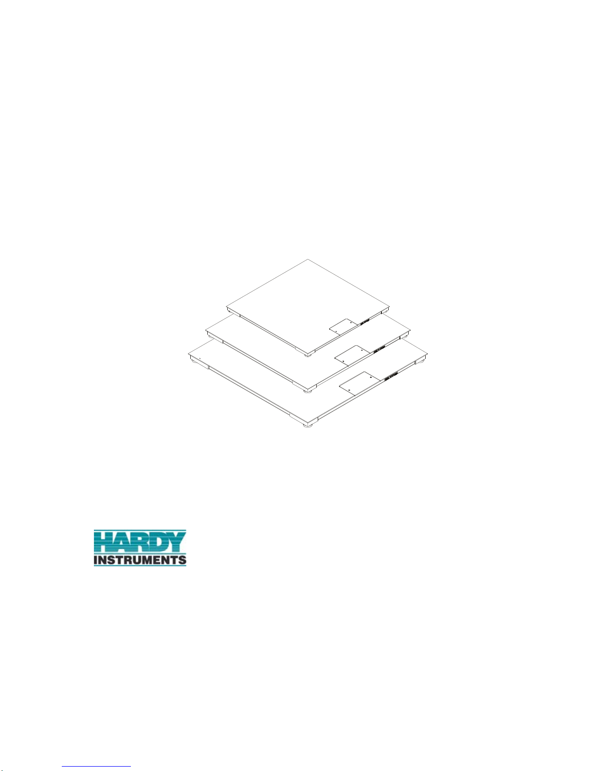
Any-Weigh™
FLOOR SCALES
OPERATION AND INSTALLATION
MANUAL
9440 Carroll Park Drive, Suite 150
San Diego, CA 92121
San Diego, CA 92123-1825
Phone: (858) 278-2900
FAX: (858) 278-6700
Web-Site: http://www.hardyinst.com
Hardy Instruments Document Number: 0596-0280-01 Rev D
Copyright October 2003 Hardy Instruments, Inc. All Rights Reserved. Printed in the U.S.A. (941028)
Local Field Service
Hardy has over 200 field technicians in the U.S., and more positioned
throughout the world to assist you in your support needs. We also have factory engineers who will travel to your facility anywhere in the world to help you
solve challenging applications. We're ready to support you with:
• Installation and start-up
• Routine maintenance and certification
• Plant audits and performance measurement
• Emergency troubleshooting and repair
To request Emergency Service and Troubleshooting, Start-up, Installation,
Calibration, Verification or to discuss a Maintenance Agreement please call
800-821-5831 Ext. 1757 or Emergency Service after hours (Standard Hours
6:00 AM to 6:00 PM Pacific Standard Time) and weekends
Ext. 1111.

Outside the U.S
Hardy Instruments has built a network of support throughout the globe. For
specific field service options available in your area please contact your local
sales agent or our U.S. factory at +1 858-292-2710, Ext. 1757.
CAUTION:
UNPACK WITH CARE
WHEN UNPACKING, DO NOT DISCARD THE PACKING CASE OR ANY
PACKING MATERIAL, UNTIL THE CONTENTS OF THE PACKING CASE
ARE INSPECTED AND CAREFULLY COMPARED WITH THE SHIPPING
DOCUMENTS.
IF ANYTHING IS UNSATISFACTORY, PLEASE NOTIFY HARDY INSTRUMENTS IMMEDIATELY BY CALLING, FAXING OR E-MAILING TO:
Hardy Service Center
HARDY INSTRUMENTS, INC.
9440 Carroll Park Drive, Suite 150
San Diego, CA 92121
Phone: (800) 821-5831
(858) 278-2900
FAX:(858) 278-6700
E-mail: disupport@hardyinst.com
Web Address: www.hardyinst.com
TO RETURN DEFECTIVE OR DAMAGED PRODUCT(S) CALL HARDY
TECHNICAL SUPPORT FOR A HARDY SERVICE TICKET NUMBER
(HST#). YOUR COMPANY NAME, ADDRESS, TELEPHONE NUMBER,
SERIAL NUMBER OF THE UNIT AND A BRIEF DESCRIPTION OF THE
PROBLEM SHOULD BE READY WHEN CALLING. FOR ALL NON-WARRANTY REPAIRS A PURCHASE ORDER OR CREDIT CARD IS ALSO
REQUIRED.
IN CASE OF DAMAGE DUE TO SHIPPING, NOTIFY THE DELIVERING
CARRIER IMMEDIATELY FOR AN INSPECTION.


Table of Contents
Table of Contents
Table of Contents - - - - - - - - - - - - - - - - - - - - - - - - - -i
Table of Illustrations - - - - - - - - - - - - - - - - - - - - - - - -I
SPECIFICATIONS - - - - - - - - - - - - - - - - - - - - - - - - - -1
Platform Material - - - - - - - - - - - - - - - - - - - - - - - - -1
Platform Height- - - - - - - - - - - - - - - - - - - - - - - - - -1
Rated Output - - - - - - - - - - - - - - - - - - - - - - - - - - -1
Excitation- - - - - - - - - - - - - - - - - - - - - - - - - - - - -1
Total Error - - - - - - - - - - - - - - - - - - - - - - - - - - - -1
Maximum Overload- - - - - - - - - - - - - - - - - - - - - - - -1
Endloading - - - - - - - - - - - - - - - - - - - - - - - - - - - -1
Temperature Range - - - - - - - - - - - - - - - - - - - - - - -1
Temperature Effect - - - - - - - - - - - - - - - - - - - - - - - -1
Cable Length - - - - - - - - - - - - - - - - - - - - - - - - - - -1
Materials of Construction - - - - - - - - - - - - - - - - - - - - -1
Steel - - - - - - - - - - - - - - - - - - - - - - - - - - - - -1
Paint - - - - - - - - - - - - - - - - - - - - - - - - - - - - -2
Foot Elastomer - - - - - - - - - - - - - - - - - - - - - - - -2
Grade Level - - - - - - - - - - - - - - - - - - - - - - - - - - -2
Accessories - - - - - - - - - - - - - - - - - - - - - - - - - - -2
Anchor Bolt Holds - - - - - - - - - - - - - - - - - - - - - -2
Approvals - - - - - - - - - - - - - - - - - - - - - - - - - - - -2
NEMA Rating- - - - - - - - - - - - - - - - - - - - - - - - - - -2
Test Criteria - - - - - - - - - - - - - - - - - - - - - - - - -2
GENERAL INFORMATION - - - - - - - - - - - - - - - - - - - - - -2
UNPACKING - - - - - - - - - - - - - - - - - - - - - - - - - - - - -3
COMPONENT DESCRIPTIONS - - - - - - - - - - - - - - - - - - -4
SITE PREPARATION- - - - - - - - - - - - - - - - - - - - - - - - -5
Precautions - - - - - - - - - - - - - - - - - - - - - - - - - - -6
FLOOR SCALE INSTALLATION - - - - - - - - - - - - - - - - - - -7
CALIBRATION - - - - - - - - - - - - - - - - - - - - - - - - - - - -10
Pre-Calibration Procedures - - - - - - - - - - - - - - - - - - - -10
C2® Second Generation Calibration - - - - - - - - - - - - - - -11
Test Weight Calibration (Hard Cal) - - - - - - - - - - - - - - - -11
i

Any-Weigh™ Series Floor Scales
Requirements: - - - - - - - - - - - - - - - - - - - - - - - -11
Material Substitution: - - - - - - - - - - - - - - - - - - - - -12
SCALE VERIFICATION- - - - - - - - - - - - - - - - - - - - - - - -12
MODEL CODE BREAKDOWN - - - - - - - - - - - - - - - - - - - -13
Mild Steel Deck, Painted - - - - - - - - - - - - - - - - - - - - -13
Stainless Steel Deck (304 SS) - - - - - - - - - - - - - - - - - -14
REMOVING SUMMING BOX COVER- - - - - - - - - - - - - - - - -15
Installing the Leveling Feet - - - - - - - - - - - - - - - - - - - -18
INSTALLING A LOAD SENSOR - - - - - - - - - - - - - - - - - - -21
OPTIONAL PIT FRAMES- - - - - - - - - - - - - - - - - - - - - - -25
About Pit Frames - - - - - - - - - - - - - - - - - - - - - - - - -25
OPTIONAL ACCESS RAMPS- - - - - - - - - - - - - - - - - - - - -29
Access Ramp Installation - - - - - - - - - - - - - - - - - - - - -29
OPTIONAL BOLT-DOWN PLATES - - - - - - - - - - - - - - - - - -31
Bolt-Down Plates Installation - - - - - - - - - - - - - - - - - - -32
OPTIONAL BUMPER GUARDS- - - - - - - - - - - - - - - - - - - -33
TROUBLESHOOTING - - - - - - - - - - - - - - - - - - - - - - - -36
INSTRUMENTATION INTERFACE CABLE COLOR CODES - - - - -37
ii

Table of Illustrations
Table of Illustrations
TABLE OF ILLUSTRATIONS- - - - - - - - - - - - - - - - - - - - -I
FIG. 1 INSTALLING THE CLOSED EYEBOLTS INTO THE TOP
PLATE - - - - - - - - - - - - - - - - - - - - - - - - - - -4
FIG. 2 SUMMING JUNCTION CARD - - - - - - - - - - - - - - - -5
FIG. 3 DIRECTION WHEN DRIVING HEAVY EQUIPMENT
ON AND OFF THE SCALE - - - - - - - - - - - - - - - -7
FIG. 4 MAXIMUM HEIGHT - - - - - - - - - - - - - - - - - - - - -7
FIG. 5 SPIRIT LEVEL- - - - - - - - - - - - - - - - - - - - - - - -8
FIG. 6 CHECKING PLATFORM LEVEL/SIDE TO SIDE - - - - - - -8
FIG. 7 CHECKING PLATFORM LEVEL/CORNER TO CORNER- - -9
FIG. 8 CHECKING PLATFORM LEVEL/DIAGONALLY - - - - - - -9
FIG. 9 ADJUSTING THE FEET FOR LEVEL - - - - - - - - - - - -10
FIG. 10 SCALE VERIFICATION/POSITION #3 - - - - - - - - - - - -12
FIG. 11 REMOVING THE SUMMING BOX COVER- - - - - - - - - -16
FIG. 12 REMOVING THE SUMMING BOX LID - - - - - - - - - - - -17
FIG. 13 REMOVING THE SUMMING BOX LID - - - - - - - - - - - -18
FIG. 14 INSERTING THE LEVELING FOOT INTO THE
LOAD SENSOR - - - - - - - - - - - - - - - - - - - - -19
FIG. 15 INSIDE VIEW - - - - - - - - - - - - - - - - - - - - - - - -20
FIG. 16 OUTSIDE VIEW - - - - - - - - - - - - - - - - - - - - - - -20
FIG. 17 ALL FOUR FEET INSTALLED - - - - - - - - - - - - - - - -21
FIG. 18 SUMMING CARD - - - - - - - - - - - - - - - - - - - - - -21
FIG. 19 CORD GRIP - - - - - - - - - - - - - - - - - - - - - - - - -23
FIG. 20 REMOVING LOAD SENSOR BOLTS AND FEET- - - - - - -24
FIG. 21 FOUNDATION FOR THE PIT FRAME - - - - - - - - - - - -26
FIG. 22 PIT FRAME DIMENSIONS- - - - - - - - - - - - - - - - - -26
FIG. 23 DRAIN INSTALLATION DIMENSIONS - - - - - - - - - - - -28
FIG. 24 EXCAVATED PIT AND SUPPORT FOR THE PIT FRAME - -28
FIG. 25 RAMP WITH RETAINER PLATES - - - - - - - - - - - - - -30
FIG. 26 INSTALLING ANCHORS FOR RAMP - - - - - - - - - - - -30
FIG. 27 BOLT DOWN PLATES/INSTALLATION - - - - - - - - - - -32
FIG. 28 BUMPER GUARD/GAP REQUIREMENT- - - - - - - - - - -33
FIG. 29 BUMPER GUARD/INSTALLATION- - - - - - - - - - - - - -34
I

Any-Weigh™ Series Floor Scales
II

Any-Weigh™ Series Floor Scales
SPECIFICATIONS
Platform Material 0.25 inch
Platform Height 3.0 inches +.275”
Rated Output 2.0mV/V ±0.1%
Excitation • Recommended 5 Volts DC
•Maximum 5 Volts DC
W ARNING FOR SCALES FITTED WITH AN INTEGRATED
TECHNICIAN SUMMING CARD, DO NOT
EXCEED 5 VDC EXCITATION. DOING SO MAY
CAUSE PROPERTY DAMAGE. DO NOT USE
WITH THESE INSTRUMENTS: HI 2160, HI
1771 OR ANY INSTRUMENT WITH AN EXCI-
TATION VOLTAGE ABOVE 5 VDC.
Total Error 0.03% of FS Output
Maximum
150% of the Rated Scale Capacity
Overload
Endloading 100% of the Rated Scale Capacity
Temperature
Range
• Safe -40º to +80º Degrees C (-40º to +176º
F)
• Compensated -10 to +40 Degrees C (+14 º to
104º Degrees F)
Temperature
Effect
• On Output - 0.0011% of load/Deg. C
• On Zero - 0.001 1% of FSO/D eg C
Cable Length 20 feet (C2 Cable)
NOTE: To purchase C2 Cable cont a c t our local Hardy Ins t r u-
ments Representative or Hardy Instruments Service
Center.
Materials of
Construction
Steel • Mild Steel: Type A36 carbon plate steel (slip
resistance - tread or smooth surface)
1

Any-Weigh™ Series Floor Scales
• Stainless Steel: Type 304 plate steel (slip
Paint 100% Acrylic Emuls ion (mild steel floor scale models
only - Stainless Steel scales are not painted)
resistance - tread or smooth surface)
Foot
• Natural Rubber (Standard)
Elastomer
Grade Level In operation, the scale must be firmly and adequately
supported at all four corners to accommodate the
maximum load in your application. The scale must be
installed to within 3º of level.
Accessories Ramps, Pit Frames, Bumper Guards, Lifting Eyebolts,
Bolt Down Plates
Anchor Bolt
Holds
1/2 inch bolts - 9/16” (.5625”) hole, 3.75 inches deep
5/8 inch b olts - 5/8” (.6250”) hole, 4.0 inches deep
Approvals • NTEP Class III Number: 04-087
NEMA Rating Summing Junction Box Enclosure - NEMA 4X Stain-
less Steel
Test Criteria Must exclude at least 65 GPM of wate from 1” inch
nozzle deliverd from a distance not less than 10 ft for
5 minutes.
GENERAL
INFORMATION
2
The Hardy Instruments AnyWeigh™ Series Floor
Scales are designed for applications that require a low
profile weighing surface with high commercial accuracy and reliability. The Hardy Floor Scales can be
configured with a complete range of accessories. The
scales can also be configured to fit any floor scale
application.
The typical platform height is three (3) inches. Each
corner can be adjusted an additional .275” (7mm) to
compensate for a non-level floor or pit mounting surface.
The Any-Weigh Floor Scales do not have bearings,
levels or moving parts that can be damaged or wear

Any-Weigh™ Series Floor Scales
out. The active elements of the floor scales are four
precision strain gauge load sensors, mounted on all
four corners of the scale platform. The unique Blind
Hole Load Introduction technology allows the foot to
move to compensate for uneven floors. This ensures
that the load forces are always applied to the load sensor at precisely the same point regardless of where the
load is placed on the scale. This ensures you will get
accurate and repeatable weighments.
Each platform load sensor is initially certified for use
in a C2
®
Second Ge neration Calibrat ion syste m.
UNPACKING The Any-Weigh Series Floor Scales are shipped fully
assembled and wired. Inspect the container for any
signs of damage that might occur during shipment.
Since almost all of the Floor Scales are shipped
F.O.B. factory, such damage is normally the responsibility of the carrier and should be reported to them.
Step 1. Remove the banding straps and any ship-
ping res traints.
WARNING DO NOT USE HOOKS OR UNCLOSED EYE-
BOLTS OR ATTEMPT TO LIFT THE SCALE
MANUALLY. FAILURE TO USE THE PROPER
LIFTING TOOLS OR LIFTING METHODS CAN
CAUSE PERSONAL INJURY OR PROPERTY
DAMAGE.
Step 2. Screw 2 closed eyebolts into the threaded
holes on the top plate of the scale. (See
Fig. 1)
• Mild Steel - 1/2 - 13 x 1.5” (Hardy Model
Number HI EB2250-1)
Step 3. Attach a chain, cable or nylon strap to the
eyebolts.
Step 4. Use a forklift or crane with rated lifting
capacity that is equal to or greater than th e
total weight of the platform scale to lift the
scale high enough to remove from the
3
Any-Weigh™ Series Floor Scales
for Lifting the
Platfor m Scale
Step 5. Be sure to use all safety precautions when
crate bottom. See Tables 2 & 3 for shipping weights.
lifting the platform so that it does not fa ll
on equipment or personnel. It is highly
recommended that blocks be placed under
the platform before working near the platform scale.
Closed Eye Bolts
COMPONENT
DESCRIPTIONS
FIG. 1 INSTALLING THE CLOSED EYE-
BOLTS INTO THE TOP PLATE
1. Steel Plate Platform - The platform material is
either low carbon steel plate or 304 stainless steel
plate. The low carbon steel platform cover is
made from a single piece of 1/4" A36 carbon
steel floor plate (skid resistant) or smooth steel
plate. The steel platforms are primed and coated
with a tough weather resistant paint (See Paint
Specifications). The 304 stainless steel platform
is made from a single piece of 1/4" diamond tread
(Conforms to ASTM A793-85) floor plate (skid
resistant) or smooth stainless steel plate with a
bead blast finish.
2. Summing Junction Card Assembly - Accessed
by unfastening the face p late on the center s ide of
the platform. (See Fig.2) The summing junction
card routes the excitation voltage to each of the
four load sensors and sums the weight signal
4
Any-Weigh™ Series Floor Scales
back from them. The C2
®
second generation
electronic calibration is included with your scale.
FIG. 2 SUMMING JUNCTION CARD
3. Load Sensors - The AnyWeigh series scales use
four (4) steel Advantage like load sensors with
hermetic seals. The output of each sensor is 2mV/
V with 5 Volts DC excitation. For more specifications see the electrical specification section of
this manual.
4. INTEGRATED TECHNICIAN™ (Option) -
(If IT summing card is installed) A built-in system diagnostics utility, continuously monitors the
weighing system for possible malfun c tions. This
capability also allows the operator to rapidly
troubleshoot a weighing system from the controller or indicator.
5. Leveling Feet - Each AnyW eigh series scale
comes with four (4) 304 s tainl ess st eel ad justable
leveling feet. The leveling feet are adjustable to a
maximum of 7mm (.275"). The leveling feet are
attached to each of the load sensors.
SITE PREPARATION • All mounting surfaces for the floor scale
should be level to within 3º, corner to corner,
end to end. Keep in mind that the adjustable
leveling feet have a maximu m adj u st men t of
7mm (.275”).
5

Any-Weigh™ Series Floor Scales
• Before welding anything on the floor scale,
contact Hardy Instruments Service Center
for instructions and precautions.
• Proper drainage must be provided to prevent
the load sensors from standing in water.
Precautions • Do not do any electric welding on or near the
platform scale.
• Do not drop items to be weighed on the
scale. Set them on the platform scale.
• Do not set items on the platform scale that
weigh more than the capacity of the scale.
• Do not store or operate the scale in environments out of the specified temperature range.
• Do not store other equipment on the scale
even temporarily when it is not used or in
storage.
• Do not allow debris to accumulate on,
around or under the scale.
• Do not set the scale in water or allow water
to accumulate around the scale. Always provide proper drainage.
• Do not let moisture get on or into any of the
electrical interconnections.
• Do not allow static or other electrical discharges go through the scale.
• Do not leave the screws for the summing
junction box cover plate loose so that the
junction box is not sealed.
• Do not drop the scale when moving or
installing.
• When driving heavy equipment on and off
the scale for weighing purposes, make sure
that you drive onto and of f of the p latform in
the direction indicated in Figure 3. Also See
Access Ramp Installation Section.
6
Any-Weigh™ Series Floor Scales
Load and unload
heavy equipment
in this direction only!
FIG. 3 DIRECTION WHEN DRIVING HEAVY
EQUIPMENT ON AND OFF THE SCALE
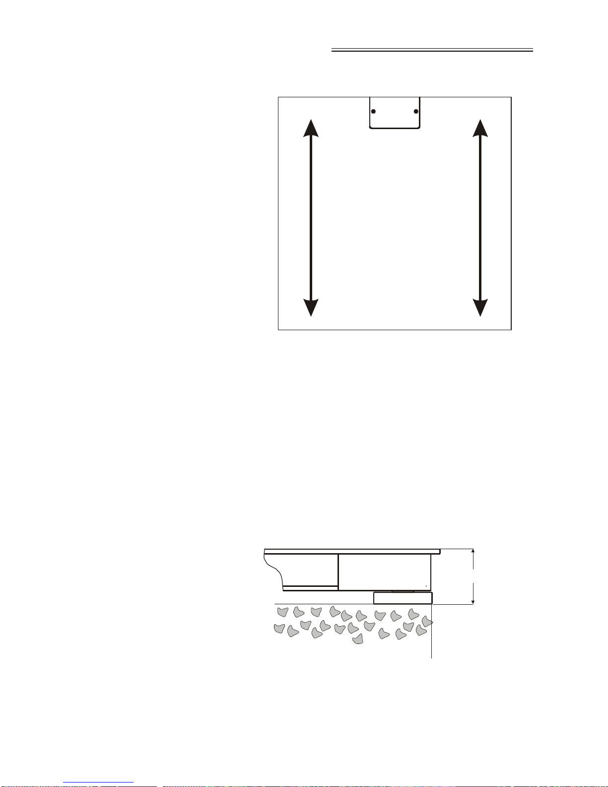
FLOOR SCALE
INSTALLATION
Step 1. Place the platform scale on the operating
location. Make sure that the platform
height is within 3 to 3.275" as measured
from the top of t he cover plat e to the to p of
the floor surface. (See Fig. 4)
NOTE: With the scale in place, the clearance ar ound the edge
of the platform and pit coping should be 1/4” to 3/8”.
3.275” (83.1 m m )
FIG. 4 MAXIMU M HEIGHT
7
Any-Weigh™ Series Floor Scales
Step 2. Make sure that the platform mounting sur-
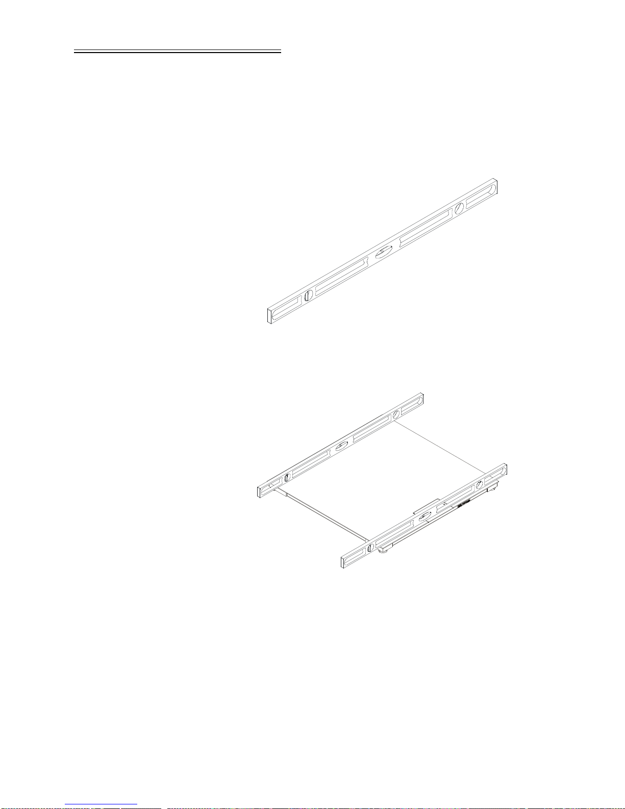
Step 3. Use a spirit level to check if the platform is
face is level to 1/8”.
level, side to side, corner to corner and
diagonally. (See Figs. 9, 10, 11, 12)
FIG. 5 SP IRIT LEVEL
FIG. 6 CHECKING PLATFORM LEVEL/SIDE
TO SIDE
8

Any-Weigh™ Series Floor Scales
FIG. 7 CHECKING PLATFORM LEVEL/COR-
NER TO CORNER
FIG. 8 CHECKING PLATFORM LEVEL/DIAG-
ONALLY
Step 4. Adjust each of the leveling feet in the
direction (either up or down), indi cated by
the level readings. (See Fig. 9)
• To increase the height rotate the foot counter
clockwise.
• To decrease the height rotate the foot clock-
wise.
9

Any-Weigh™ Series Floor Scales
Foot
CALIBRATION
Pre-Calibration
Procedures
FIG. 9 ADJUSTING THE FEET FOR LEVEL
Step 5. Place a spirit level on the platform surface
again to check the adjustment for level.
Keep adjusting the legs until the platform
is level and all four leveling feet are firmly
on the floor surface.
Step 6. Check the distance from the top of the
platform to the floor surface at each corner. All the measurements should be
within 3º of each other and the platform
should be level.
Step 7. If the installation requires bolt down pl ates
to keep the floor scale in place go to the
Optional Bolt Down Plates Section for
instructions.
Step 1. Open the Junction box cover. (See Fig. 11
for Instructions)
Step 2. Thread the C2
the grommet on the side of the scale that
houses the junction box.
®
Certified cable through
10

Any-Weigh™ Series Floor Scales
Step 3. Connect the C2 Certified Summing Card
Interface Cable to the weight instrument.
Color code wires as follows:
• + Excitation Red
•+ Sense Blue
• + Signal Green
• - Signal White
•- Sense Brown
• - Excitation Black
•+ C2 Grey
•- C2 Violet
Step 4. Use the weight instrument/indicator m an-
ual for ca libration in st r uctions.
NOTE: To purchase C2
Hardy Representative or the Hardy Instruments Service Center.
®
C2
Second
Generation
Calibration
Definiti on - C2® electronically calibrates a scale system without the need for test weights. This feature is
in all Hardy weight or rate controllers, and in the
Allen-Bradley weight modules.
Step 1. Refer to the Hardy weight or rate control-
ler manuals or the Allen Bradley module
manual for instructions.
Test Weight
Calibration (Hard
Cal)
Requirements: • Test weight calibration requires the use of
certified class F test weights equal to a minimum of 80% of the rated scale capacity.
• Three weights between 10% and 100% of
the scale capacity should be used to check
the mid range.
• Several low capacity weights equivalent to
one or two instrument divisions are required
to check the systems' sensitivity .
®
certified cable, contact your local
11

Any-Weigh™ Series Floor Scales
Positi on #2
Material
Substitution:
• When certified test weights are not available
you can use an accurately weighed material
instead.
• The material must be weighed on a secondary, calibrated scale and delivered to the site
of the primary floor scale for calibration.
• The secondary calibrated scale should be of
the same accuracy or greater and have a
capacity approximately equal to the primary
floor scale.
SCALE VERIFICATION Step 1. Get a test weight that is equal to 10% of
the full scale capacity.
Step 2. Place the test weight at Position #1 on th e
platform. (See Fig. 10)
Positi on #3
Summing Box
Positi on #4
Positi on #1
FIG. 10 SCALE VERIFICATION/POSITION #3
Step 3. Write down the weight for position #1.
Step 4. Place the weight at position #2.
Step 5. Write down the weight for position #2.
Step 6. Place the weight at position #3.
Step 7. Write down the weight for position #3.
Step 8. Place the weight at position #4.
Step 9. Write down the weight for position #4.
Step 10. Check all the readings. If all the readings
are within an acceptable tolerance, no recalibration is required.
12

MODEL CODE
BREAKDOWN
Mild Steel Deck,
Painted
Any-Weigh™ Series Floor Scales
Step 11. If all the readings are not within an accept-
able tolerance contact the Hardy Instruments Service Center.
Tread Plate Deck
Painted
MODEL MODEL LBS KGS Feet CM
HI AFSU303001-41T HI AFSU303001-41S 1000 454 30” x 30” 76 x 76 200
HI AFSU3301-41T HI AFSU3301-41S 1000 454 3’ x 3’ 91 x 91 250
HI AFSU3302-41T HI AFSU3302-41S 2500 1134 3’ x 3’ 91 x 91 250
HI AFSU4402-41T HI AFSU4402-41S 2500 1134 4’ x 4’ 122 x 122 405
HI AFSU4405-41T HI AFSU4405-41S 5000 2268 4’ x 4’ 122 x 122 405
HI AFSU4410-41T HI AFSU4410-41S 10000 4536 4’ x 4’ 122 x 122 405
HI AFSU4505-41T HI AFSU4505-41S 5000 2268 4’ x 5’ 122 x 152 500
Smooth Plate Deck
Painted
CAPACITY Overall Size
Ship
Wght
LBS
(KGS)
(91)
(113)
(113)
(184)
(184)
(184)
(227)
HI AFSU4510-41T HI AFSU4510-41S 10000 4536 4’ x 5’ 122 x 152 500
HI AFSU4605-41T HI AFSU4605-41S 5000 2268 4’ x 6’ 122 x 183 600
HI AFSU4610-41T HI AFSU4610-41T 10000 4536 4’ x 6’ 122 x 183 600
HI AFSU5505-41T HI AFSU5505-41T 5000 2268 5’ x 5’ 152 x 152 650
HI AFSU5510-41T HI AFSU5510-41T 10000 4536 5’ x 5’ 152 x 152 650
(227)
(272)
(272)
(295)
(295)
Table 1: Mild Steel, Painted
13

Any-Weigh™ Series Floor Scales
Tread Plate Deck
Painted
MODEL MODEL LBS KGS Feet CM
HI AFSU5705-41T HI AFSU5705-41T 5000 2268 5’ x 7’ 152 x 213 900
HI AFSU5710-41T HI AFSU5710-41S 10000 4536 5’ x 7’ 152 x 213 900
HI AFSU6810-41T HI AFSU6810-41S 10000 4536 6’ x 8’ 183 x 244 1150
Smooth Plate Deck
Painted
CAPACITY Overall Size
Ship
Wght
LBS
(KGS)
(408)
(408)
(522)
Table 1: Mild Steel, Painted
Stainless Steel
Deck (304 SS)
Tread Plate
Stainless Steel
Deck
Smooth Stainless
Steel Deck
CAPACITY Overall Size
Ship
Wght
MODEL MODEL LBS KGS Feet CM
HI AFSU303001-43T HI AFSU303001-43S 1000 454 30” x 30” 76 x 76 200
HI AFSU3301-43T HI AFSU3301-43S 1000 454 3’ x 3’ 91 x 91 250
HI AFSU3302-43T HI AFSU3302-43S 2500 1134 3’ x 3’ 91 x 91 250
HI AFSU4402-43 T H I AFSU44 02 -43 S 2500 1134 4’ x 4’ 122 x 122 405
HI AFSU4405-43 T H I AFSU44 05 -43 S 5000 2268 4’ x 4’ 122 x 122 405
HI AFSU4410-43 T H I AFSU44 10 -43 S 10000 45 36 4’ x 4’ 122 x 122 405
HI AFSU4505-43 T H I AFSU45 05 -43 S 5000 2268 4’ x 4’ 122 x 152 500
HI AFSU4510-43 T H I AFSU45 10 -43 S 10000 45 36 4’ x 5’ 122 x 152 500
LBS
(KGS)
(91)
(113)
(113)
(184)
(184)
(184)
(227
(227)
HI AFSU4605-43 T H I AFSU46 05 -43 S 5000 2268 4’ x 6’ 122 x 183 600
14
(272)
Table 2: Stainless Steel

Any-Weigh™ Series Floor Scales
Tread Plate
Stainless Steel
Deck
MODEL MODEL LBS KGS Feet CM
HI AFSU4610-43T HI AFSU4610-43T 10000 4536 4’ x 6’ 122 x 183 600
HI AFSU5505-43T HI AFSU5505-43T 5000 2268 5’ x 5’ 152 x 152 650
HI AFSU5510-43T HI AFSU5510-43T 10000 4536 5’ x 5’ 152 x 152 650
HI AFSU5705-43T HI AFSU5705-43T 5000 2268 5’ x 7’ 152 x 213 900
HI AFSU5705-43T HI AFSU5705-43S 10000 4536 5’ x 7’ 152 x 213 900
HI AFSU6810-43T HI AFSU6810-43S 10000 4536 6’ x 8’ 183 x 244 1150
Smooth Stainless
Steel Deck
CAPACITY Overall Size
Ship
Wght
LBS
(KGS)
(272)
(295)
(295)
(408)
(408)
(522)
Table 2: Stainless Steel
REMOVING SUMMING
BOX COVER
Step 1. Use a phillips screwd river and remove the
two flat head machine screws that fasten
the summing box cover to the floor scale
frame. (See Fig. 11)
15

Any-Weigh™ Series Floor Scales
FIG. 11 REMOVING THE SUMMING BOX
COVER
Step 2. Gently pull the frame cover out of the
enclosure. You now have access to the
summing junction box C2 Cer tif ied C a ble
as shipped.
Step 3. Using a phillips head screw drive r remove
all the screws that fasten the cover to the
summing box. (See Fig. 12)
16

Any-Weigh™ Series Floor Scales
FIG. 12 REMOVING THE SUMMING BOX LID
Step 4. Take the lid off the junction box so that
you can see all the wiring from the load
sensors and to the instrument/indicator.
(See Fig. 13)
17

Any-Weigh™ Series Floor Scales
Installing the
Leveling Feet
FIG. 13 REMOVING THE SUMMING BOX LID
Step 1. Remove the lock bolt and nut from the lev-
eling fo ot .
Step 2. With the scale raised and securely
blocked, insert the leveling foot into the
load sensor. Make sure the through hole in
the foot is aligned with the bottom through
hole on the load sensor. (See Fig. 14)
18

Any-Weigh™ Series Floor Scales
FIG. 14 INSERTING THE LEVELING FOOT
INTO THE LOAD SENSOR
NOTE: You may need to push with a little force due to some
interference caused by the O-ring that is attach ed to
the foot. DO NOT USE A HAMMER OR TRY TO
DRIVE THE FOOT INTO THE HOUSING.
Step 3. With the through holes aligned, insert the
lock bolt going from the cen ter of the scale
outward. This eliminates having to remove
the load sensors when installing the lock
bolt.
Step 4. Screw the nut onto the lock bolt until it is
tight. The feet should look like the following: (See Figs. 15 & 16)
19

Any-Weigh™ Series Floor Scales
FIG. 15 INSIDE VIEW
20
FIG. 16 OUTSID E VIEW
Step 5. Install all four (4) feet. (See Fig. 17)

Any-Weigh™ Series Floor Scales
FIG. 17 ALL FOUR FEET INSTALLED
INSTALLING A LOAD
SENSOR
Step 1. Shut all power off to the floor scale.
Step 2. To gain access to the Summing Card fol-
low the instructions above. You do not
have to remove the summing card or the
bottom of the Junction box to install a new
load sensor. (See Fig. 18)
FIG. 18 SUMMING CARD
21

Any-Weigh™ Series Floor Scales
Table 3: Summing Card Load Sensor Connectors
Step 3. Use a small slotted head screw driver and
Load Sensor # Connector
Load Sensor #1 TB1
Load Sensor #2 TB2
Load Sensor #3 TB3
Load Sensor #4 TB4
To Instrument TB5
disconnect the Load Sensor cable. It is a
good idea to mark the wires if the wire
markers have been removed. Color code
wires are as follows:
• + Excitation Red
• + Signal Green
• - Signal White
• - Excitation Black
•+ C2 Grey
•- C2 Violet
Step 4. Loosen the cord grip nut for the load sen-
sor cable you want to remove. (See Fig.
19)
22

Any-Weigh™ Series Floor Scales
FIG. 19 CORD GRIP
Step 5. From the load sensor pull the cable out of
the junction box and through the channel
until all the cable has been removed.
Step 6. Use the closed eye bolts and chain, cable
or nylon strapping to lift the floor scale
high enough to remove the load sensor or
turn the scale completely over and let the
top plate rest on blocks for ea sier access to
the feet.
Step 7. Block the floor scale adeq uately so that the
platform will not drop on any machinery
or personnel.
Step 8. Remove the lock bolt on the load sensor
foot you are removing. Store in a safe
place so that you don’t forget to install it.
Step 9. Pull the load sensor leveling foot out of the
load sensor.
Step 10. Use a socket wrench and remove the two
bolts that fasten the load sensor to the
mount.
Step 11. Lift the load sensor out of the housing.
23

Any-Weigh™ Series Floor Scales
Bolts
Load Cell
FIG. 20 REMOVING LOAD SENSOR BOLTS
AND FEET
Step 12. Place the new load sensor so that the
through bolt holes are aligned with the
threaded mounting holes and in the same
direction as the old load sensor. DO NOT
CUT OR REUSE THE OLD CABLE ON
THE NEW LOAD SENSOR.
Step 13. Screw in the two (2) load sensor bolts that
fasten the load sensor to the mount.
Tighten the bolts finger tight.
Step 14. Use a Torque Wrench and tighten the bolts
to the torque rating in Table 4. It is a good
idea to switch back and forth between each
bolt until the torque value has been
reached.
24
BOLT Grade Torque
.500 - 20 UNC
(M12 8.8)
5 65 Ft/Lbs (90 Nm)
Table 4: To rque Specifications for Load Sensor
Bolts

Any-Weigh™ Series Floor Scales
Step 15. Run the load sensor cable through the
channel to the summing box. Bundle up
any excess cable and store it in the channel. DO NOT CUT THE CABLE TO
MAKE IT FIT BETTER. If you cut the
cable, you will not get correct readings
from the load sensors.
Step 16. Reconnect th e cable wires accord ing to the
color code in Step 3 to the correct load
sensor connector.
OPTIONAL PIT
FRAMES
About Pit Frames The pit frame optional accessory is a one-piece
welded unit with no additional welding required.
There are 3 different type frames with many sizes for
each type. This accessory is designed for in-floor or
'flush' applications. In general, a hole is cut in the concrete, the pit-frame accessory is installed in the hole,
then concrete is poured around and under the frame.
Once cured, the scale platform is set into the frame
and installation can be completed.
Standard duty frames are available in mild steel or
stainless steel for all the floor scale sizes. The concrete work and frame setting is usually done by a contractor, with a scale technician completing the project
by setting and installing the scale.
• A soil bearing pressure of at least 1,000 lbs
per square foot is required. The corner pier
should be designed to support at least two
thirds of the total capacity of the scale.
• A 3/4” diameter conduit for the scale inter-
face cable is recommended. The pit frame is
arranged with a 1 1/8” diameter hole for a
cable exit. Locate the conduit to match the
hole location.
Step 1. Place the pit frame in the approximate
position it will occupy on the floor. (See
Fig. 21)
25

Any-Weigh™ Series Floor Scales
3.43 75 (8 7. 3 mm )
8” Typ
FIG. 21 FOUNDATION FOR THE PIT FRAME
Step 2. Mark out the position of the hole to be
11” (279.4mm)
made. The hole MUST be a minimum of
12" larger than the pit frame on all sides.
(See Fig. 22)
26
8” Typ
FIG. 22 PIT FRAME DIMENSIONS

Any-Weigh™ Series Floor Scales
Model Number
HI APF3310-3 3’ x 3’ 91cm x 91cm Stainless Steel
HI APF4410-3 4’ x 4’ 122cm x 122cm Stainless Steel
HI APF4510-3 4’ x 5’ 122cm x 152cm Stainless Steel
HI APF4610-3 4’ x 6’ 122cm x 183cm Stainless Steel
HI APF5510-3 5 x 5 152cm x 152cm Stainless Steel
HI APF5710-3 5’ x 7’ 152cm x 213cm Stainless Steel
HI APF6810-3 6’ x 8’ 183cm x 244cm Stainless Steel
Platform Size
Feet
Platform Size CM Material
Table 5: Pit Frame Stainless Steel/Model Numbers and Dimensions
Model Number
Platform Size
Feet
Platform Size CM Material
HI APF3310-1 3’ x 3’ 91cm x 91cm Mild Steel
HI APF4410-1 4’ x 4’ 122cm x 122cm Mild Steel
HI APF4510-1 4’ x 5’ 122cm x 152cm Mild Steel
HI APF4610-1 4’ x 6’ 122cm x 183cm Mild Steel
HI APF5510-1 5 x 5 152cm x 152cm Mild Steel
HI APF5710-1 5’ x 7’ 152cm x 213cm Mild Steel
HI APF6810-1 6’ x 8’ 183cm x 244cm Mild Steel
Ta ble 6: Pit Frame Mild Steel/Model Numbers and Di mensions
Step 3. Should pit drainage be required, slope the
pit floor to an installed drain while maintaining a level area at each corner. (See
Fig. 23)
27

Any-Weigh™ Series Floor Scales
4” (101.6 m m )
2 x 4
Pit
FIG. 23 DRAIN INSTALLATION DIMENSIONS
Step 4. The hole will have to be deep enough to
11” (279.4mm )
Drain
accommodate the pit coping, plus the
thickness of the pit floor. (See Fig. 24)
Wire
Frame Assembly
FIG. 24 EXCAVATED PIT AND SUPPORT FOR
THE PIT FRAME
Step 5. Set the frame in the hole supported at
about the correct height.
Step 6. Set two 2 x 4 's on edge (longer than the
width of the hole) across the opening. (See
Fig. 7)
Step 7. Use soft wire and make 2 loops by twist-
ing wire around each 2 x 4 and the frame
Step 8. With the frame supported by the wire and
2 x 4's, use a spirit level to set the frame
flush with the surrounding floor, level the
frame to within 1/8”, corn er to co rner, side
to side and diagonally, and at the correct
height by twisting or untwisting the wires.
(See Fig. 7)
Step 9. Concrete specifications:
• At least 6” thickness of concrete is required
for pit floor in Non-Hostile applications.
28

Any-Weigh™ Series Floor Scales
• At least an 11” concrete floor with a mini-
mum of 3” bottom slope is required if drainage is required for hostile applications. A 4”
drain is highly recommended.
• Make sure the conduit for the scale cable is
in place and secured into the frame opening.
• Pour the concrete around and under the
frame ensuring a smooth and level finish. It
is recommended that f = 3500 psi and 3” to
4” slump concrete be used.
• If a drain is required, form the pit to place a
slope in the pit floor to the drain. (See Fig.
23)
• Cure to a minimum of 2000 psi before pull-
ing the interface cable through the conduit.
Step 10. Pull the interface cable through the con-
duit.
OPTIONAL ACCESS
RAMPS
Access Ramp
Installation
Optional access ramps are available in low carbon
steel or stainless steel. The low carbon ramps are constructed of Skid Resistant (tread) A36 low carbon
steel floor plate. The Stainless Steel ramps are constructed of 304 Stainless Steel, diamond tread floor
plate. All ramps are thirty inches (30") (76.2 centimeters) long in the direction of travel and provide a 5º
degree incline.
Step 1. Determine which side of the floor scale
you want the access ramp to be placed.
Consider the location of the summing
junction box access plate. It canno t be covered by the access ramp. (See Fig. 26)
Each mild steel ramp accessory comes
with two integral bolt-down plates and
four anchors.
Step 2. Place the ramp in position, then lift and set
the platform feet into the bolt-down plate
holes. (See Fig. 25)
29

Any-Weigh™ Series Floor Scales
FIG. 25 RAMP WITH RETAINER PLATES
Step 3. Drill the two (2) outer holes using a ham-
Step 4. Insert the anchor bolts with the nut and
mer drill. (See Specifications/Anchor B olt
Holds above for hole dimensions)
washer already ON. (See Fig. 26)
30
FIG. 26 INSTALLING ANCHORS FOR RAMP

Any-Weigh™ Series Floor Scales
Step 5. Tap the anchor bolt into the hole th en
tighten the nuts securely.
Step 6. Lift the Platform out and away form the
bolt-down plate.
Step 7. Drill the two (2) inner holes using a ham-
mer drill. (See Specifications/Anchor B olt
Holds above for hole dimensions)
Step 8. Insert the anchor bolts with the nut and
washer already ON.
Step 9. Tap the anchor bolts into the hole then
tighten the nuts securely
Step 10. Note the following:
• If two ramps are installed, NO other bolt-
down plates are needed
• If one ramp is installed then a set of two bolt-
down plates are needed.
• Only two ramps total may be installed on
opposite sides of a scale platform.
OPTIONAL BOLTDOWN PLATES
Bolt down plates are used to keep the scale from sliding or moving when loads are applied. The plates are
bolted via anchors at each of the scales feet. (See Fig.
27)
Model Num b ers
Kit
Stainless Mild Steel
4 Plates
8 Bolts
2 Plates
4 Bolts
HI ABDP1-3 HI ABDP1-1
HI ABDP2-3 HI ABDP2-1
Table 7: Bolt Down Plates and Anchor Bolts
31

Any-Weigh™ Series Floor Scales
FIG. 27 BOLT DOWN PLATES/INSTALLA-
TION
NOTE: The platform has been removed for clarity purposes.
Bolt-Down Plates
Installation
Step 1. Place the Platform Scale in position.
Step 2. Place the bolt-down plate under the foot,
plate edge should extend out from under
the scale.
Step 3. Drill two (2) holes using a hammer dr ill.
(See Specifications/Anchor Bolt Holds
above for hole dimensions) Insert anchor
bolts with the nut and washer already
attached.
Step 4. Tap the anchor bolts into the hole then
tighten the nuts securely.
Step 5. Repeat this process for each plate used in
your installation.
32

Any-Weigh™ Series Floor Scales
NOTE: If ramps are NOT installed and bolt-down plates are
needed, then a set of four (4) bolt-down plates are
required.
OPTIONAL BUMPER
GUARDS
Bumper guards are designed to help protect the platform from direct hits from forklift traffi c. The guards
are slightly higher than the scale and will help deflect
the forks.
Step 1. Place the bumper guard so it will protect
the platform from non-scale traf fic and not
touch or interfere with the platform’s
movement. (See Figs. 28 & 29)
FIG. 28 BUMPER GUARD/GAP REQUIRE-
MENT
33

Any-Weigh™ Series Floor Scales
FIG. 29 BUMPER GUARD/INSTAL LATION
Step 2. Drill the holes using a hammer drill. (See
Step 3. Insert the anchor bolts with the nut and
Step 4. Tap the anchor bolts into the hole then
Specifications/Anchor Bolt Holds above
for hole dimensions)
washer already installed.
tighten the nuts securely.
Bumper Guard Material Length
Model # Ft cm lbs Kg
HI ABG03-1
HI ABG03-3
Mild Steel
Stainless Steel
3 9 1 100 45.36 HI AFSU3301-4XT
Shipping
Wght.
Use on Scale
Model #
HI AFSU3302-4XT
HI AFSU3301-4XS
HI AFSU3302-4XS
Table 8: BUMPER GUARD MODEL NUMBERS AND COMPATI BILIT Y
CHART
34

Any-Weigh™ Series Floor Scales
Bumper Guard Material Length
Model # Ft cm lbs Kg
HI ABG04-1
HI ABGO4-3
HI ABG05-1
HI ABG05-3
Mild Steel
Stainless Steel
Mild Steel
Stainless Steel
4 1 22 125 56.70 HI AFSU4402-4XT
5 1 52 150 81.65 HI AFSU4505-4XT
Shipping
Wght.
Use on Scale
Model #
HI AFSU4405-4XT
HI AFSU4410-4XT
HI AFSU4505-4XT
HI AFSU4510-4XT
HI AFSU4605-4XT
HI AFSU4610-4XT
HI AFSU4402-4XS
HI AFSU4405-4XS
HI AFSU4410-4XS
HI AFSU4505-4XS
HI AFSU4510-4XS
HI AFSU4605-4XS
HI AFSU4610-4XS
HI AFSU4510-4XT
HI AFSU5505-4XT
HI AFSU5510-4XT
HI AFSU5510-4XT
HI AFSU5705-4XT
HI AFSU5710-4XT
HI AFSU4505-4XS
HI AFSU4510-4XS
HI AFSU5505-4XS
HI AFSU5510-4XS
HI AFSU5705-4XS
HI AFSU5710-4XS
HI ABG06-1
HI ABG06-3
HI ABG07-1
HI ABG07-3
HI ABG08-1
HI ABG08-3
Mild Steel
Stainless Steel
Mild Steel
Stainless Steel
Mild Steel
Stainless Steel
Table 8: BUMPER GUARD MODEL NUMBERS AND COMPATI BILIT Y
6 1 83 135 61.24 HI AFSU4605-4XT
HI AFSU4610-4XT
HI AFSU6810-4XT
HI AFSU4605-4XS
HI AFSU4610-4XS
HI AFSU6810-4XS
7 2 13 190 86.18 HI AFSU5705-4XT
HI AFSU5710-4XT
HI AFSU5705-4XS
HI AFSU5710-4XS
8 2 44 245 111.13 HI AFSU6810-4XT
HI AFSU6810-4XS
CHART
35

Any-Weigh™ Series Floor Scales
NOTE: To purchase optional equipment for the AnyWeigh
Floor Scales, contact your local Hardy Representative or Hardy Instruments Service Center.
TROUBLESHOOTING 1. Check all cables to be sure that they have no
cracks, cuts or crimps. Check for broken cables.
2. Check for loose fitting connections.
3. Look for the presence of moisture at all connections and under or near the summing junction box
cover.
4. Look for struct ural changes in the platform scale
and supporting structures.
5. Periodically check to see if the platform is level.
Problem: Scale does not respond when a weigh t is placed on the
platform.
Cause #1: Packing material or debris wedged or built up under-
neath the platform
Cause #2: Platform scale is not wired correctly to the weigh
instrument.
Cause #3: Weigh Process Controller Malfunction
Remedies: • Carefully lift the platform high enough to
safely remove the built up debris.
• Check for loose connections or broken wires .
• Check the wiring color code to be sure that
the wires are routed correctly. If they are not
wired correctly change the wiring until it is
correct.
• Check the Weighing Instrument Manua l for
trouble shooting instructions.
Problem: Scale indication is not linear.
Cause #1: Packing material or debris wedged or built up under-
Remedy #1: • Carefully lift the platform high enough to
Cause #2: Weight Instrument or floor scale is not calibrate d.
36
neath the platform
safely remove the built up debris.
• Check for loose connections or broken wires .

Any-Weigh™ Series Floor Scales
Remedy #2: • Re-calibrate either the weight instrument or
the floor scale or both.
• Check for corrosion on the electrical connections.
Problem: The scale reading drifts or is erratic.
Cause#1: Corrosion or moisture in the electrical connections.
Remedy #1: • Check to see that the summing junction box
is tightly fastened.
• Check to see that the gaskets and seals are
not cracked or damaged.
• Remove the wires and clean any corrosion
from the connectors and exposed wire.
• For high humidity areas, place a desiccant
packet in the summing junction card enclosure.
Cause#2: High voltage wires close to the load sensor cable.
Remedy #2: Move the high voltage wires away from the load sen-
sor cable.
Cause #3: Instrument or floor scale imprope rly grounded (i.e.
one or both not to connected to earth ground).
Remedy #3: Make sure that the weigh instrument and the floor
scale platform cover are both connected to earth
ground.
Cause #4: High static electricity present.
Remedy #4: Install a ground strap from the floor scale platform
cover to earth ground.
WARNING DO NOT CONNECT THE GROUND STRAP
NEAR OR ON THE LOAD SENSORS. THEY
ARE GROUNDED THROUGH THE SUMMING
JUNCTION BOX. TO DO SO WILL DAMAGE
THE LOAD SEN SO RS .
INSTRUMENTATION
INTERF ACE CABLE
COLOR CODES
-EXCITATION RED
+SENSE BLUE
37

Any-Weigh™ Series Floor Scales
+SIGNAL GREEN
-SIGNAL WHITE
-SENSE BROWN
-EXCITATION BLACK
+C2 GREY
-C2 VIOLET
SHIELD ORANGE
38

Numerics
304 stainless steel platform 1-4
A
About Pit Frames 1-25
Acceptable Tolerance 1-13
Access Ramp Installation 1-29
Accessories 1-2
Active Elements 1-3
Allen Bradley Module Manual 1-11
Approvals 1-2
Attach a Chain 1-3
B
Blind Hole Load Introduction Technology 1-3
Index
Block the Floor Scale 1-23
Bolt-Down Plates Installation 1-32
Bundle 1-25
C
C2 Certified Summing Card Interface Cable 1-11
C2® Certified Cable 1-10
C2® Second Generation Calibration 1-11
C2® Second Generation Calibration system 1-3
Cable Length 1-1
Calibration 1-10
Chain 1-23
Closed Eye Bolts 1-23
Color Code Wires 1-22
Commercial Accuracy 1-2
Component Descriptions 1-4
Conduit 1-25
Cord Grip Nut 1-22
Corner to Corner 1-5
Cure 1-29

Any Weigh™ Series Floor Scales
D
Diamond Tread Floor Plate 1-29
Direct Hits 1-33
E
End to End 1-5
Endloading 1-1
Excitation 1-1
Eyebolts 1-3
F
Flat Head Machine Screws 1-15
Floor Scale Installation 1-7
Foot Elastomer 1-2
Forklift 1-3
Forklift Traffic 1-33
G
Grade Level 1-2
H
Hammer Drill 1-30
Hardy Floor Scales 1-2
Hardy Instruments AnyWeigh™ Series Floor Scales 1-2
Hardy Instruments Service Center 1-6
Hardy Weight or Rate Controller Manuals 1-11
Hostile Applications 1-29
I
Increase the Height 1-9
Inner Holes 1-31
Installing A Load Sensor 1-21
Installing the Leveling Feet 1-18
Instrument/Indicator 1-17
Instrumentation Interface Cable Color Codes 1-37
Integrated Technician™ (Option) 1-5

L
Level Readings 1-9
Leveling Feet 1-5
Load Forces 1-3
Load Sensor Bolts 1-24
Load Sensors 1-5
Loops 1-28
M
Material Substitution 1-12
Maximum Overload 1-1
Mild Steel Deck, Painted 1-13
Mild Steel Ramp 1-29
Model Code Breakdown 1-13
Index
N
Natural Rubber 1-2
NEMA 4X 1-2
NEMA Rating 1-2
Non-Hostile Applications 1-28
Non-Level Floor 1-2
Non-Scale Traffic 1-33
Nylon Strap 1-3
Nylon Strapping 1-23
O
Optional Bolt Down Plates 1-10
Optional Bolt-down Plates 1-31
Optional Bumper Guards 1-33
Optional Pit Frames 1-25
P
Paint 1-2
Phillips Screwdriver 1-15
Pit Coping 1-28
Pit Drainage 1-27
Pit Floor 1-28

Any Weigh™ Series Floor Scales
Pit Mounting Surface 1-2
Platform Height 1-1
Platform Material 1-1
Position #1 1-12
Position #2 1-12
Position #3 1-12
Position #4 1-12
Pre-Calibration Procedures 1-10
Precautions 1-6
Proper Drainage 1-6
R
Rated Lifting Capacity 1-3
Repeatable Weighments 1-3
Requirements 1-11
S
Safety Precautions 1-4
Scale Platform 1-25
Scale Verification 1-12
Site Preparation 1-5
Skid Resistant 1-29
Slotted Head Screw Driver 1-22
Socket Wrench 1-23
Soft Wire 1-28
Soil Bearing Pressure 1-25
Spirit Level 1-8
Stainless Steel Ramps 1-29
Steel 1-1
Steel Plate Platform 1-4
Summing Card 1-21
Summing Junction Card Assembly 1-4
T
Temperature Effect 1-1
Temperature Range 1-1
Test Criteria 1-2

Test Weight Calibration 1-11
Test Weight Calibration (Hard Cal) 1-11
Torque Wrench 1-24
Total Error 1-1
Troubleshooting 1-36
U
Unpacking 1-3
W
Welding 1-6
Index

Any Weigh™ Series Floor Scales
 Loading...