

Page 1
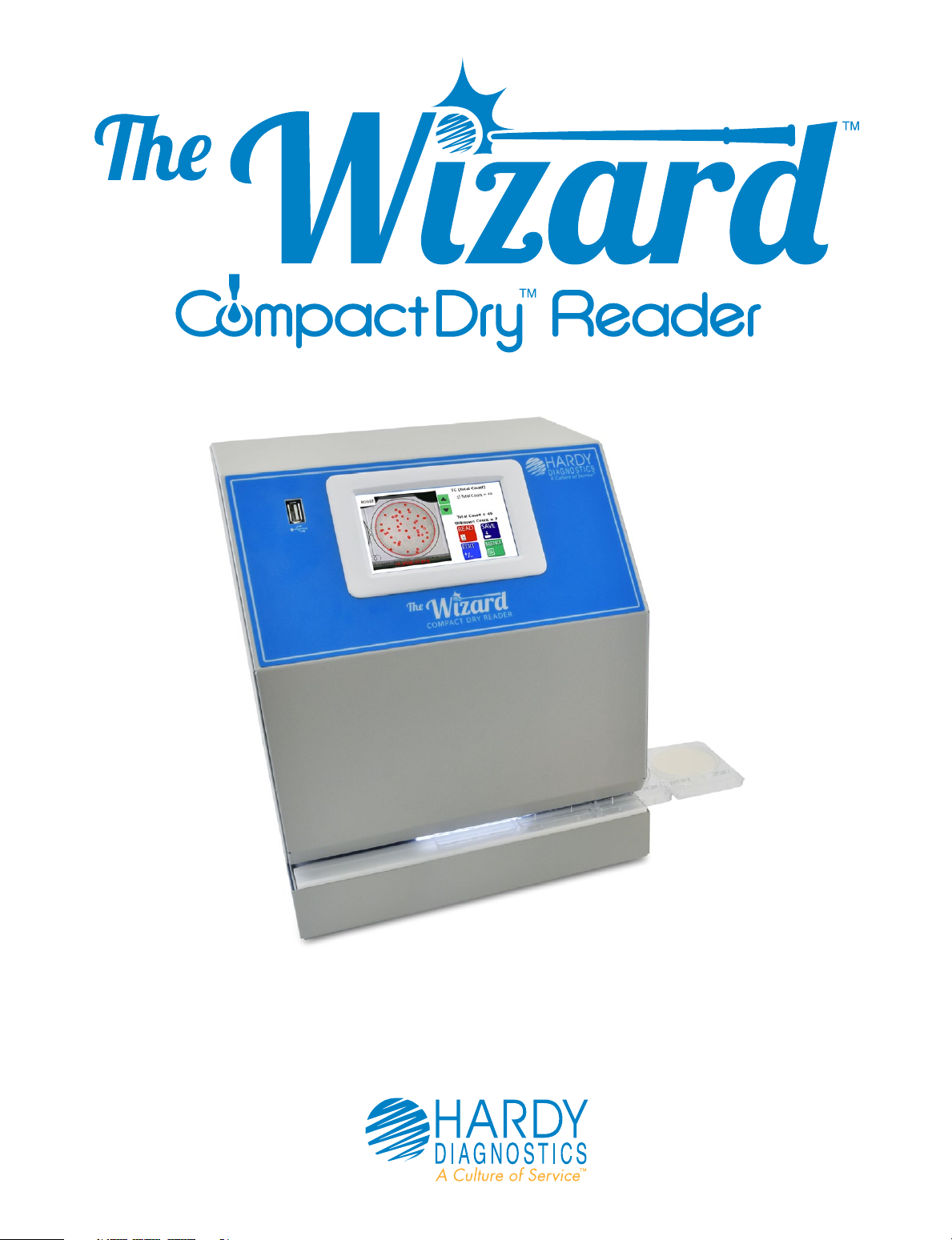
Operating Instructions
Page 2

Table of Contents
General Information and Warnings ............ 1
How to Get the most from your
CompactDry™ plates and The Wizard™
CompactDry™ Reader .................................... 2
Getting Started ................................................. 3
Equipment Overview .................................. 4-5
General Operation ........................................... 6
User Interface ...............................................7-14
Advanced Configuration
and Passcode ............................................15-20
USB Removal and Power Down ......... 21-22
How to connect to the Hardy Data
Receiver Program ................................... 23-24
Connecting USB Thermal Printer ............25
Accessories.......................................................26
Limitations ........................................................ 27
Specifications ..................................................28
Warranty and Service ................................... 29
Our Advantage .............................................. 30
1430 West McCoy Lane
Santa Maria, CA 93455
800.266.2222
HardyDiagnostics.com
Page 3

General Information and Warnings
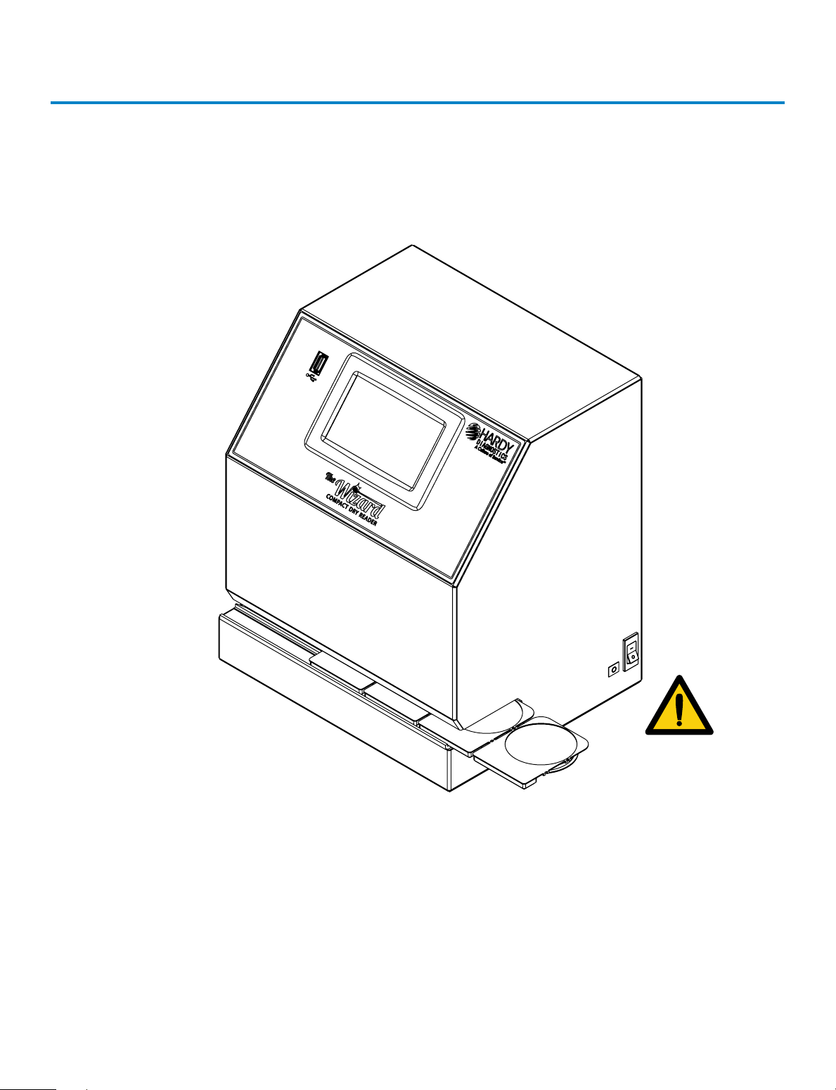
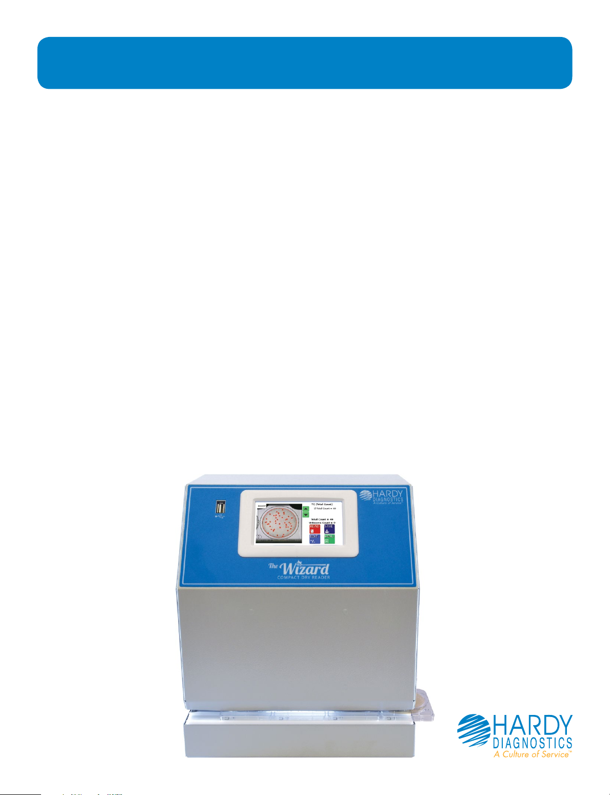
The Wizard™ CompactDry™ Reader is designed to read and document CompactDry™
culture media plate colony counts with a color interpretation. The Wizard™ CompactDry™ Reader has selectable modes in the configuration menu designed to read the
various types of CompactDry™ plates.
Notable Symbols and Precautions:
Caution: Read these operating instructions fully before use and pay
attention to sections containing this symbol.
Always observe the safety precautions as specified by the
operating instructions.
• If liquid is spilled inside the unit, immediately disconnect it from the
power supply and contact Technical Support.
• Clean the unit only with a damp cloth; do not use chemical or abrasive
cleaning agents.
• Before moving, disconnect at the power supply socket.
• Connect only to a power supply with voltage corresponding to that on
the serial number label.
• Ensure that the main switch and power supply connector are easily
accessible during use.
• After transport or storage in humid conditions, dry out the unit before
connecting it to the supply voltage.
Technical Support: 800-266-2222, option 2
1
Page 4

How to Get the most from your CompactDry™
plates and The Wizard™ CompactDry™ Reader
Whether your lab is an established CompactDry™ user or in the process of validating its
use, it is important that the proper use of the CompactDry™ plate products will greatly
enhance the performance of The Wizard CompactDry™ Reader. Please note these important points and refer to the IFU (Instructions For Use) for each of the CompactDry™
plates:
• Carefully read through each section of this manual and the IFU for each CompactDry™ plate, conveniently located within the Hardy website, HardyDiagnostics.com
• Validate sample matrices and adjust settings as needed according to this manual
before use.
• It is highly recommended to use a stomacher bag and filter the homogenized sample prior to inoculation to eliminate carry over of tiny particles onto the surface of
the CompactDry™ medium. Small particles may interfere with photo optic detection
mechanism.
• During and after incubation, keep the lid tight on the plates to avoid any possible
dehydration.
• An additional dilution may be needed when the sample has a dark color, which is
can be indicative of a high bioburden. Individual colonies may not be distinguishable
on trays if concentrations are above 100 CFU/ml. In general, additional 1:10 dilutions
will allow colonies to be visualized. The Wizard™ CompactDry™ Reader has a maximum detection limit of 150 CFU; however the sample should be diluted to a concentration of less than 100 CFU/ml for best results. Refer to the procedure section and
general dilution guidelines in the IFU for each plate type.
2
Page 5
Getting Started
Unpacking
Remove the packing materials carefully, and keep for future shipment or storage
of the unit.
The Wizard™ CompactDry™ Reader includes:
• Reader....................................................................................................1 piece
• Power Supply and international adapters ...............................1 piece
• USB Flash Drive with Hardy Data Receiver Program ..........1 piece
• Warranty Card ....................................................................................1 copy
• Operating Instructions ....................................................................1 copy
• Quick Start Guide for setup ..........................................................1 copy
Instrument Placement
1. Place The Wizard™ CompactDry™ Reader on a solid, level surface so that there
is at least 10cm of clearance from adjacent walls. Ensure that the power switch,
USB ports, and the ventilation slots on the side of the unit are free from
obstruction.
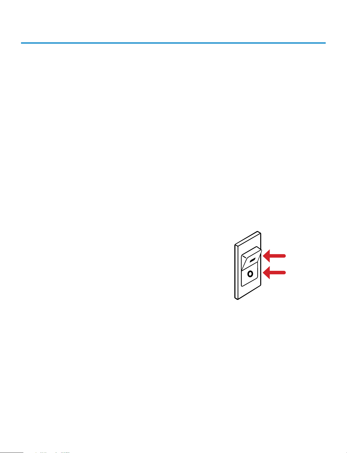
2. Ensure the power switch is set to the OFF position
before connecting to the power source.
3. Connect The Wizard™ CompactDry™ Reader to the power supply. Plug power
supply into an appropriate electrical outlet.
4. Switch the unit to the ON position utilizing the power ON/OFF switch located
on the right side of the instrument.
ON
OFF
System Accessories
Accessories are available for purchase to suit your laboratory work-flow. See
page 26.
Technical Support: 800-266-2222, option 2
3
Page 6
Equipment Overview
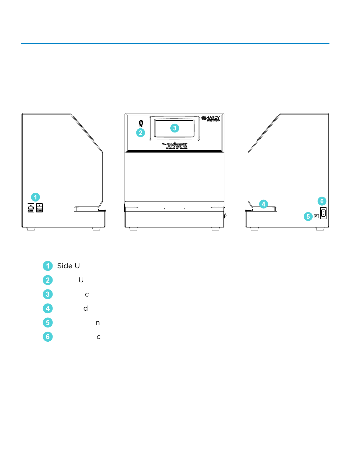
Main System Components
1
Side USB Connection (2x)
1
Front USB Connection (1x)
2
Touch Screen Interface
3
2
3
4
6
5
Plate Indexing Tray
4
Power Connection Port
5
Power Switch
6
4
Page 7
Equipment Overview (continued)
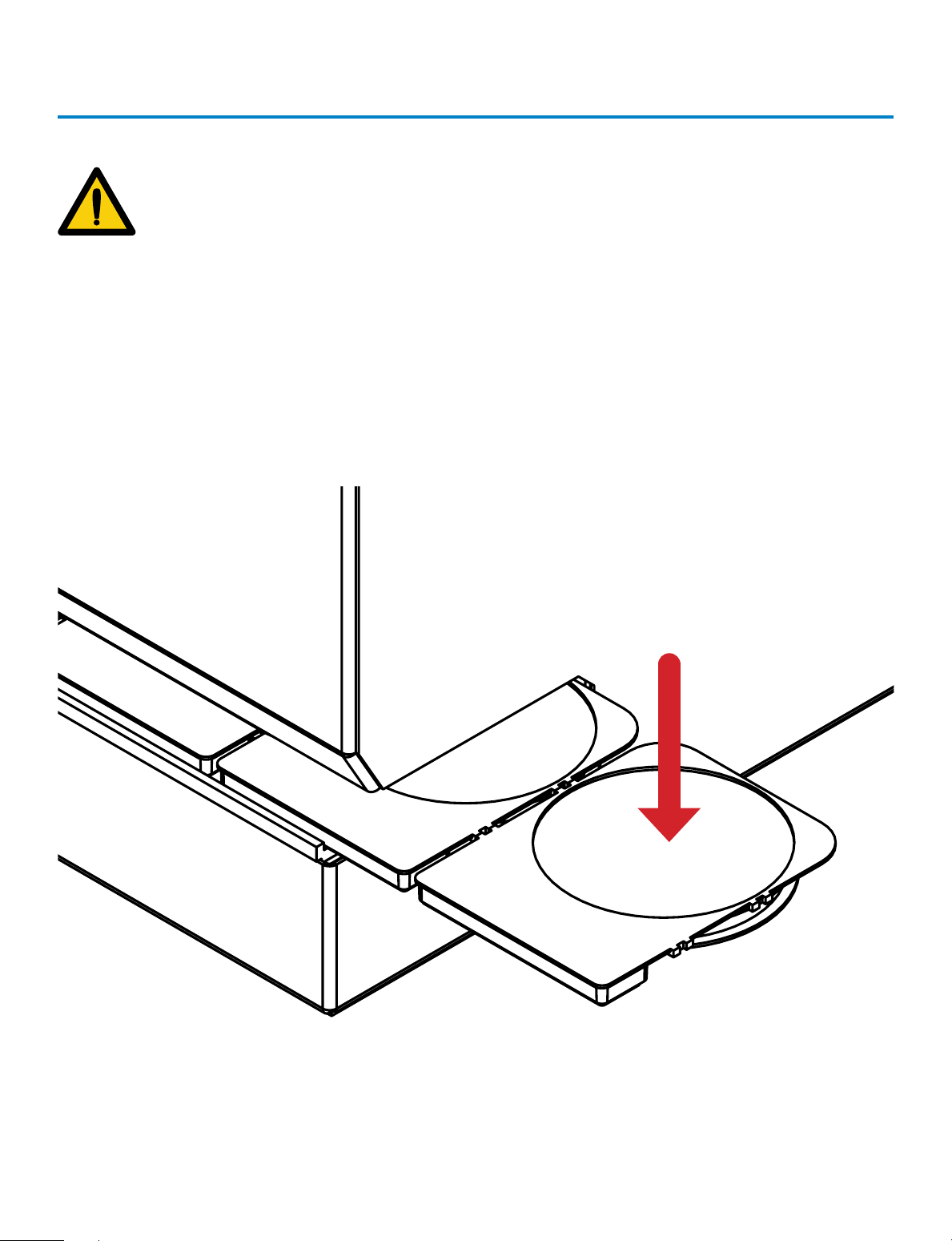
PLATES MUST BE INSERTED WITH THE LIDS
AFFIXED TO THE BASE AND
FACING DOWNWARD. FAILURE TO INSERT
PLATES PROPERLY MAY CAUSE INCORRECT
PLATE COUNTS, SYSTEM ERRORS, DAMAGE,
OR CONTAMINATION.
Technical Support: 800-266-2222, option 2
5
Page 8
General Operation
The system has been designed to accept and index only CompactDry™ plates.
CompactDry™ plates must be inserted face down with the lids on.
Plates face down
with lids on
1. Make sure the outside of the plates are dry and free of debris and the plate lids
are securely fitted.
2. Plates can be inserted in connected sets or one at a time.
3. Turn plate(s) so lid is facing down.
4. Hold the CompactDry™ plates by the raised rectangular tab.
5. Slide the plates into the unit from either the right or left hand side.
6. The first plate will “click” into place when positioned correctly for imaging.
6
Page 9
User Interface
Home Screen Operation
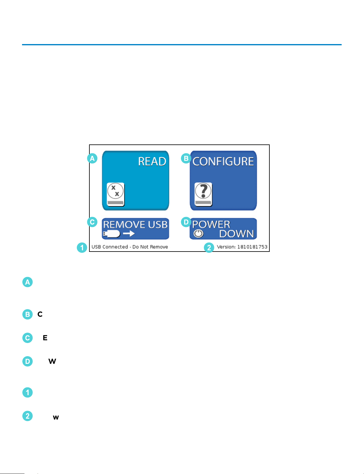
The Home Screen is the first screen displayed after the unit is done initializing upon
powering on. From the Home Screen, the operator can navigate to the Read Screen
where CompactDry™ plates are imaged and analyzed. The operator can also configure
the system and change the sensitivity via the Configure Screen. The Home Screen is
also used to safely remove a USB flash drive.
🇦
🇨
1
READ – Accesses the Read Screen. From the Read Screen, CompactDry™ plates
🇦
are imaged, colonies are counted, analyzed, and the data is saved
(complete guide pg. 8).
CONFIGURE – Used to adjust settings and change the unit data saving settings
🇧
(complete guide pg. 13).
🇧
🇩
2
REMOVE USB – Used to safely remove a USB Flash Drive. Errors can occur if the
🇨
USB Flash Drive is removed incorrectly (complete guide pg. 21)
POWER DOWN – Used to properly shut down the unit. Press the power down
🇩
button before turning o the main power switch to ensure proper
shutdown (complete guide pg. 22).
1
USB Flash Drive Status – This portion of the screen displays USB Flash Drive
connection status.
2
Software Version Information – This area of the screen displays information on the
system software version.
Technical Support: 800-266-2222, option 2
7
Page 10
Read Screen Operation
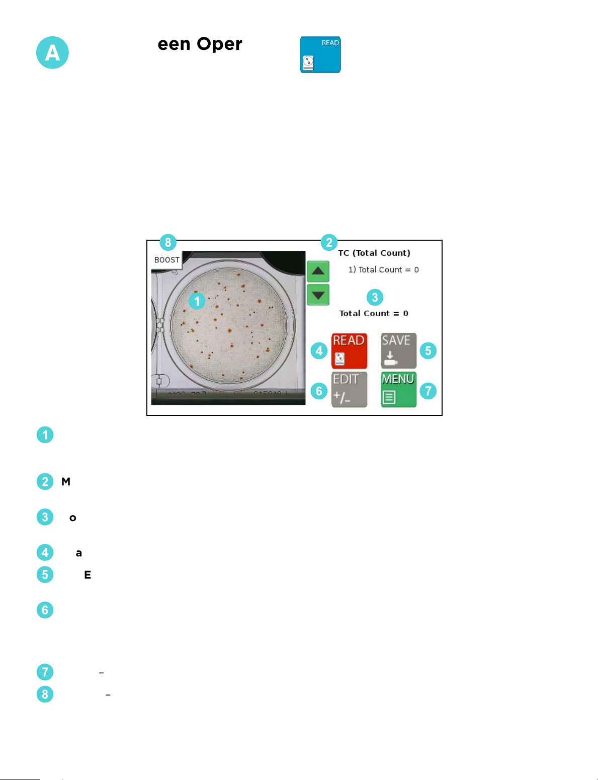
The Read Screen includes features that allow the user to count the number of colonies
on a CompactDry™ plate, access the Edit functions, and access the Save Screen. Within
the Read Screen are the following functions:
• Read Screen
• Edit Screen
• Save Screen
Be sure The Wizard™ CompactDry™ Reader is set to the proper CompactDry™ plate that is
being read before using the READ function. Reference the MODE name at the top of the
screen to ensure the unit is set to the proper plate type.
8
1
4
2
3
5
6 7
Video/Image Feed Window – The initial video feed of the plate is displayed in this win-
1
dow. Once the image is analyzed, the colonies will be highlighted and counted. To clear
the highlighted colonies, touch anywhere on the image and the marks will be cleared.
Mode Name – The text in the top right-hand side of the display shows the current plate
2
mode. Make sure the mode matches the type of plates being imaged.
Count Output – The middle section of the right-hand side of the display contains the
3
colony count data. This data can then be saved and/or printed.
Read Button – Read the image in the Video/Image Feed Window.
4
SAV E – Save the data to a USB Flash Drive and/or print the data to a USB thermal printer.
5
The Save Button will be inactive (gray in color) until the plate is read.
EDIT – In some cases, overlapping colonies may aect The Wizard™ CompactDry™
6
Reader’s ability to obtain a proper plate count. The Edit Button allows the user to correct
the reading before the data is saved to a USB flash drive, or printed with the USB thermal
printer. The Edit Button will not be active (gray in color) until the plate is read.
MENU – Returns the operator to the home screen.
7
BOOST – Raises the camera sensitivity to colony size and chromogenic reaction during
8
analysis, and can be used when lighter or smaller colonies are dicult to detect.
8
Page 11
READ SCREEN (Post Reading)
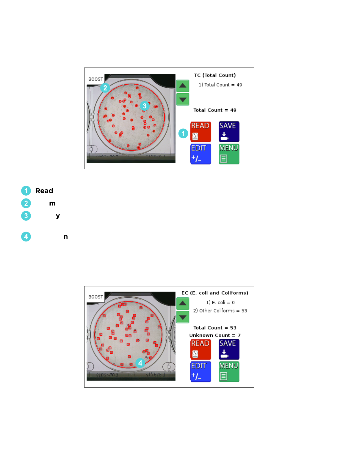
After the image has been read, The Wizard™ CompactDry™ Reader will automatically
direct you to the Post Read Screen.
2
3
1
Read Initiated – Can be used to re-read the plate if edits are applied.
1
Perimeter Marks – The perimeter of the plate is detected and marked in red.
2
Colony Marks – Colonies are circled in a specific color. The color and design of the
3
marker can be changed in the Markers Screen (see pg. 13).
Unknown Colony Marks – The Unknown Colonies are marked with an “x” by
4
default and counted separately. The color and design of the marker can be
changed in the Markers Screen. Unknown count is recorded for any debris or
particulate that is on the plate. This function is turned o by default.
4
Technical Support: 800-266-2222, option 2
9
Page 12
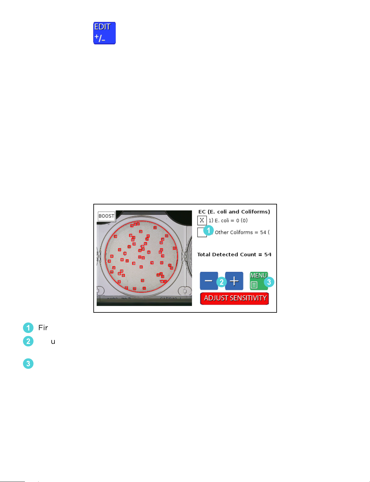
Edit Screen
This feature is for manually adjusting colony counts. For QC and validation purposes,
please use the Advanced Configuration feature (see pg. 15). This feature will not change
how a colony is categorized, it will only change if it is recognized. A more in depth
method is required if the colony is not categorized correctly.
Within the Edit Screen are the following functions:
• Plate designation/colony type check
• Colony count adjustment
• Adjust screen sensitivity
• Boost function
If The Wizard™ CompactDry™ Reader is not detecting all colonies due to overlap or
obscurity, users have three options to adjust their plate count.
1
32
First, select the type of colonies that require a count adjustment.
1
Adjust the count with the -/+ buttons. The image will not change but will add or
2
remove colonies numerically to the selected colony type.
Exit back to the read screen with the MENU button. The updated count can now
3
be saved to the USB or printed with the thermal printer.
10
Page 13
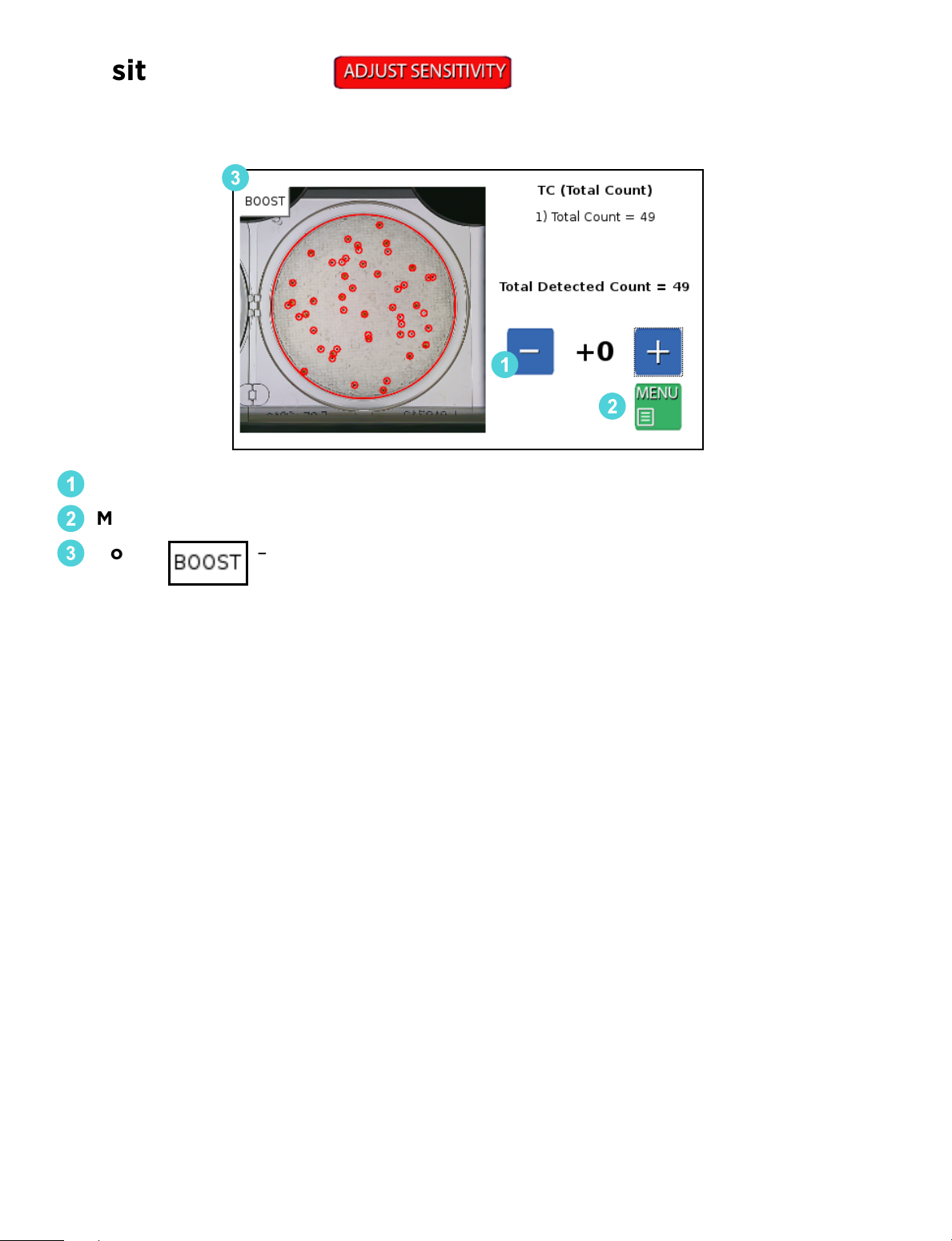
Sensitivity Screen
Allows user to manually raise or lower camera sensitivity preferences.
3
1
2
- / + Buttons - Adjust the sensitivity up/down to all the colonies.
1
Menu – Press the Menu button to exit to Sensitivity Screen.
2
Boost – Can be calibrated through
3
Advanced Configuration (see pg. 15).
Technical Support: 800-266-2222, option 2
11
Page 14
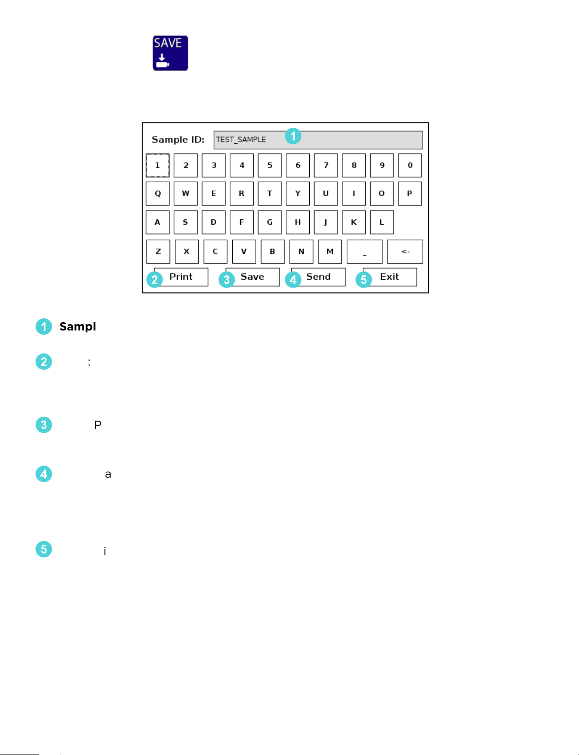
Save Screen
Users have the ability to save their data in dierent ways:
1
3 4 52
Sample ID: Enter the name of the sample or identification number. Optional
1
Barcode Scanner or USB Keyboard can also be used to input this data.
Print: The Print Button will send the data to the USB thermal printer. Sample ID,
2
colony count data and images of the plate will be printed in black and white.
Based on the configurations setting, the camera will print the raw image and/or the
image with the markers.
Save: Plate count data will be saved to a USB drive as a CSV file listed by the
3
Sample ID. The image of the plate with or without the markers can also be saved to
the USB.
Send: Data can be sent to PC, LIMS, or the Hardy Data Receiver Program (HDRP,
4
see pg. 23) by use of the USB to Ethernet adapter. For established LIMS
(Laboratory Information Management System) integration, users will need to work
with their LIMS provider to integrate the The Wizard™ CompactDry™ Reader into
their software.
5
Exit: This enables the user to exit the keyboard function and return to the
previous screen.
12
Page 15
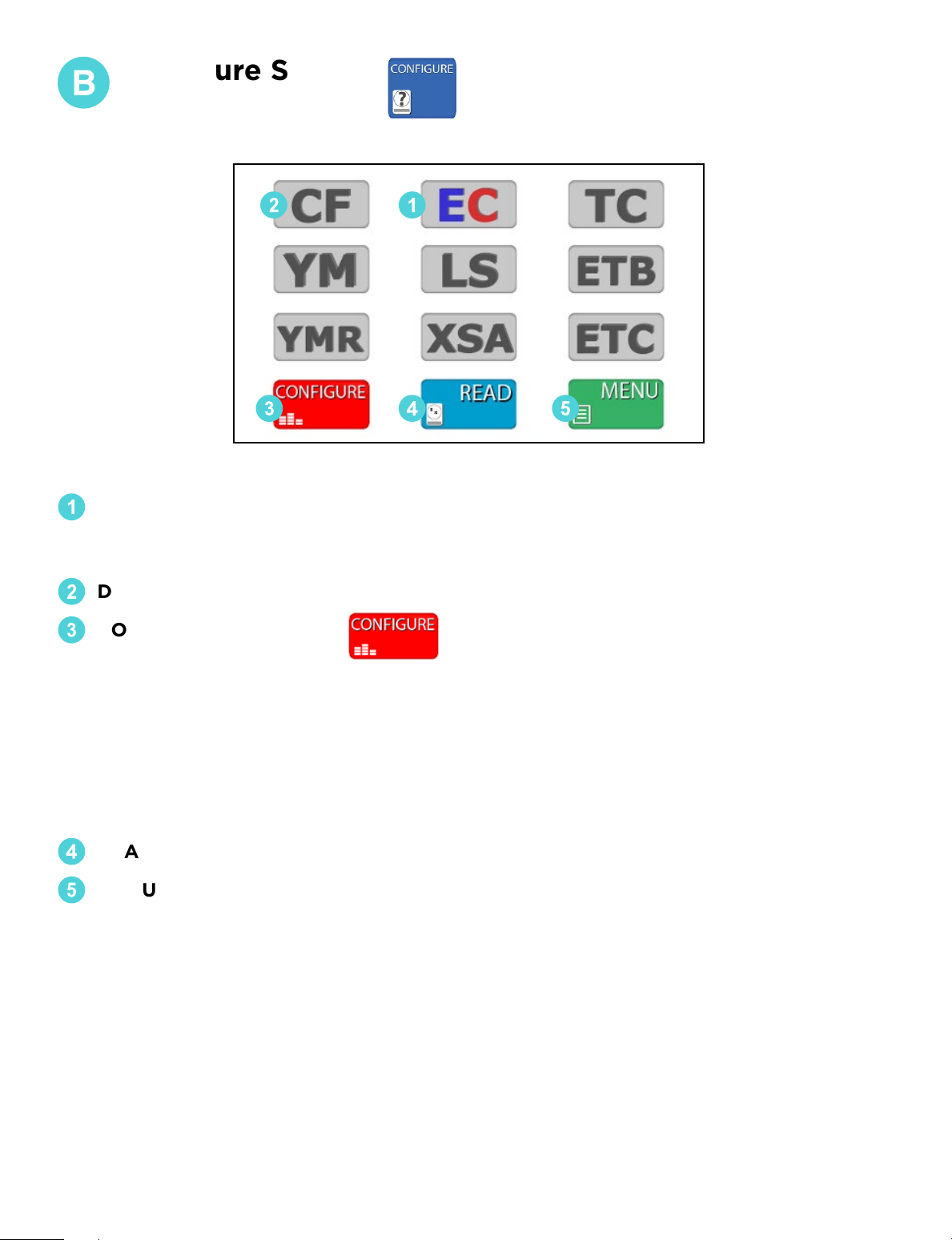
Configure Screen
2 1
3 4 5
SELECTED PLATE – Will appear in color.
1
Make sure this mode matches the type of CompactDry™ plate the operator is
reading.
DESELECTED PLATES – The deselected mode buttons will appear in gray.
2
CONFIGURE SETTINGS –
3
From the Configure Screen, users can access the following options (see pg. 14):
• Adjust markers
• Save image
• Save markers
• Review plates stored on USB
• Live Imaging
• Advanced Configuration
READ - Returns the operator to the Read Screen.
4
MENU – Returns the operator to the Home Screen.
5
Technical Support: 800-266-2222, option 2
13
Page 16
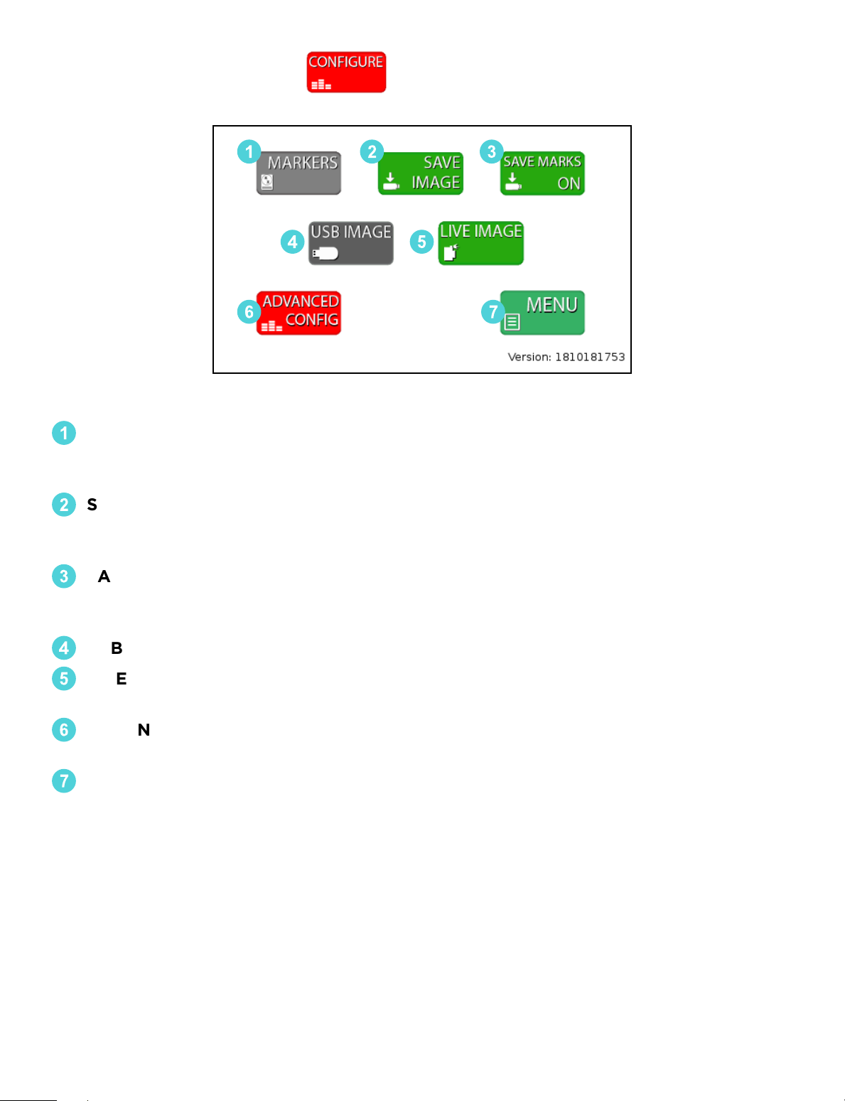
Configure Settings
2 31
4 5
6 7
MARKERS: Colony count markers can be customized to plate type. Users have the
1
option to change the color, shape, weight, and size of the markers for dierent
plate modes.
SAVE IMAGE/SAVE DATA ONLY: When this option is highlighted green, saved files
2
will include an image of the plate with the corresponding plate read data. When
option is in gray, saved files will include only the raw data from the plate read.
SAVE MARKERS ON/OFF: When this option highlighted green for ON, saved files
3
will include two images, one with colony markers and the original raw image of the
plate. When option is gray, saved file will only include raw image of plate.
USB IMAGE: Allows users to review and read plates stored on a USB drive.
4
LIVE IMAGE: The default setting for the Wizard reader allows users to read
5
CompactDry™ plates in real time.
ADVANCED CONFIGURATION: This option will be used when calibrating and
6
validating The Wizard™ CompactDry™ Reader for your sample matrix.
MENU: Takes users back to plate mode configuration screen.
7
14
Page 17
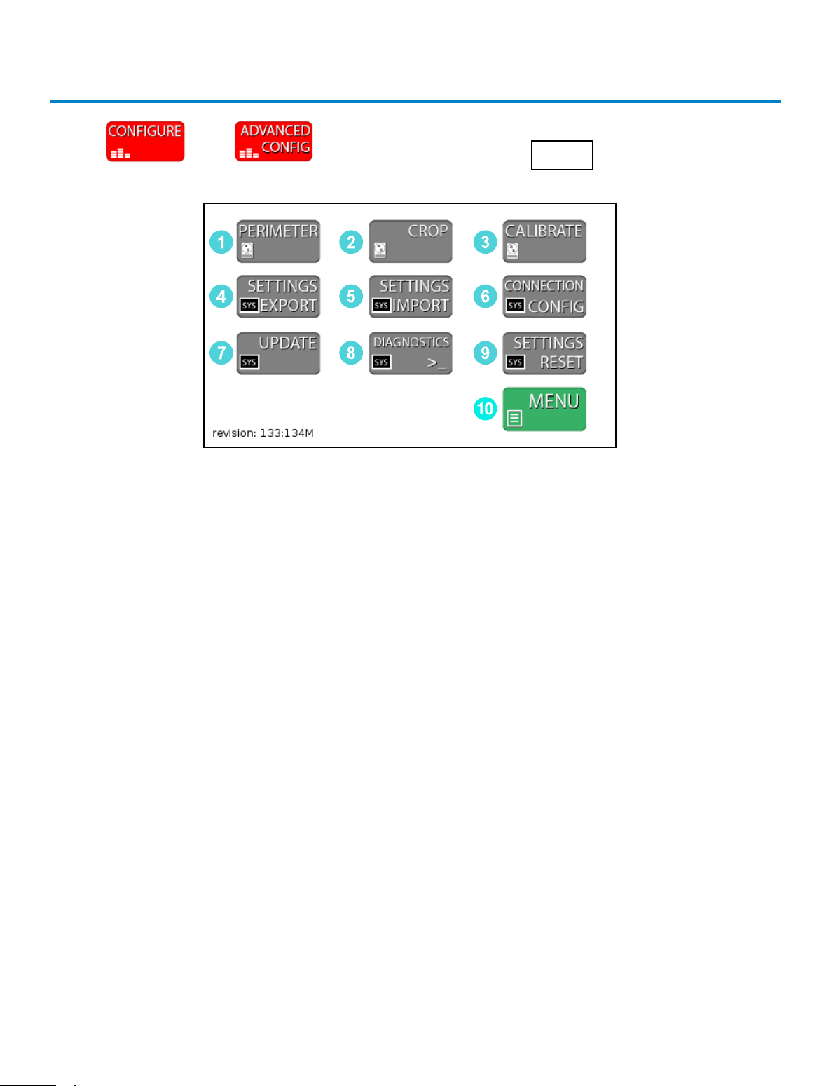
Advanced Configuration
Press then and then enter the code 0855 to enter the
Advanced Configuration screen.
1
4
7
1. PERIMETER - Used to adjust the settings for perimeter detection. This is set during
the factory calibration and should not require adjustment.
2. CROP - Used to adjust the settings for cropping the image. This is set during the
factory calibration and should not require adjustment.
3. CALIBRATE - Enters the CALIBRATE Screen. The CALIBRATE Screen is where the
operator can calibrate the colony detection settings.
4. SETTINGS EXPORT Button – Used to save the Calibration data and system settings
to a USB drive. This can then be used to calibrate an additional unit with the
SETTINGS IMPORT Button.
2
5
8
3
6
9
10
5. SETTINGS IMPORT Button – Used to save new Calibration data and system settings
to the unit from a USB drive. Settings can be updated easily with the SETTINGS
IMPORT Button
6. CONNECTION CONFIG Button – Used to connect the Thermal Printer and HDRP
or LIMS systems. Once these devices are connected, use this menu to detect and
update the communication settings.
7. UPDATE Button – If the system requires a Firmware Update via USB drive, this
button is used to load the new firmware onto the unit.
8. DIAGNOSTICS Button - For factory use only.
9. SETTINGS RESET Button– Resets to the original factory settings.
10. MENU Button- Returns user to CONFIGURE screen.
Technical Support: 800-266-2222, option 2
15
Page 18

Unit Calibration – Calibrating the Unit
If the system is not detecting colonies it will require calibration. The Wizard detects
colonies based on the contrast between the background color and the colonies. It
then determines if the colony is to be counted by checking it against a color and size
profile. The color is made up of Blue, Green and Red values. There are two methods
to calibrate the unit eectively.
1. Quick Sensitivity Adjustment – If a unit is not detecting colonies, the Sensitivity
can be quickly adjusted in the EDIT screen from the Sensitivity Button. However, it is
recommended to perform a complete calibration as listed in the next steps below.
This method is designed to be a quick work around for “on the fly” sensitivity
adjustments which are normally accomplished with a complete calibration. This
method will not change how a colony is categorized, it will only change if it is
recognized so a more in-depth method is required if the colony is not categorized
correctly. Press to proceed with the adjustment.
2. Configuration Menu Method – The Configuration Menu Method breaks the calibration into two parts. This is the recommended method for configuring the unit for
quality control prior to use.
a. Sensitivity Screen – Determines what is a colony or detected object based on
contrast sensitivity and size. A boost function is added for enhanced detection of
pinpoint colonies and may be calibrated separately in the same screen.
b. Colony Type Screen – The Colony Type looks at all detected objects and deter-
mines if the object is the colony of interest based on color and size. For modes that
detect multiple types of organisms (YM and EC), multiple Colony Type Screens are
used. A boost function is added for enhanced detection of pinpoint colonies and
may be calibrated separately in the same screen(s).
Summary – If a colony is not detected, the Sensitivity requires adjustment. If a colony
is detected but it is classified incorrectly then the Colony Type Screen will be used to
calibrate the unit. Both adjustments are required to complete a full calibration for
quality control. An added boost function for enhanced sensitivity may be calibrated
during normal calibrations.
16
Page 19
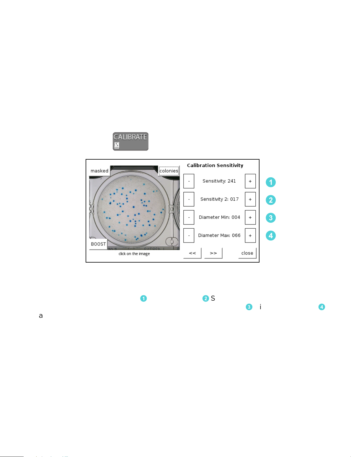
CALIBRATION SENSITIVITY Screen
The calibration screen can be accessed from the Configuration Menus. The first
calibration screen detects all objects on the plate. A second and sometimes third
filter will determine the type of colony detected. Make sure the unit is in the
correct mode before calibrating. The unit will take a still image of the plate during
calibration to limit distortion of the sample. The unit will not operate as quickly as
in the READ Screen because it is updating and performing calculations. All - / +
buttons in the Calibration screens are dual action. They can be pressed once for
fine adjustment or held down for large adjustments. Every time the calibration
values are changed the unit will update the detection algorithms.
CALIBRATION BUTTON:
1
2
3
4
1. The first step of calibrating the unit is to determine the best settings for picking
up all the objects on the plate. 1 Sensitivity and 2 Sensitivity 2 adjustments
determine how sensitive the unit is to detecting objects. The 3 Diameter Min and 4
Diameter Max adjustments are used to filter out items too small or too big,
respectively.
2. The second step of the calibration is calibrating the unit to count the correct
colonies.
3. The third step (if necessary) is calibrating the unit to count a second type of
colony like the YM (Yeast and Mold Mode) or EC (E. coli and Other Coliform Mode).
4. Steps 1-3 may be repeated to calibrate the Boost function which allows for
enhanced sensitivity.
Technical Support: 800-266-2222, option 2
17
Page 20
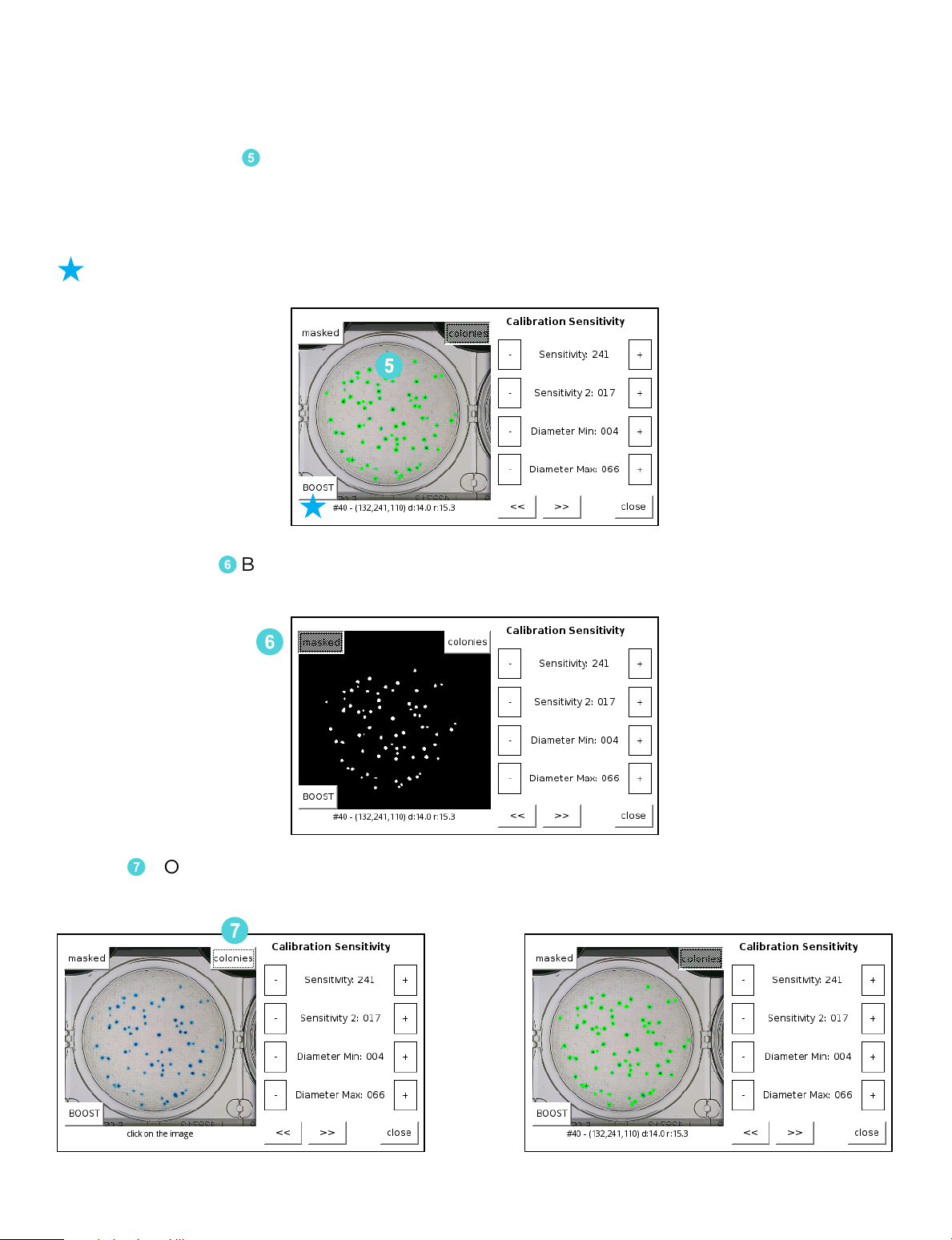
Visualization Tools for the Calibration Sensitivity Screen
There are three tools in this screen that assist in the Sensitivity calibration.
1. A picture of the 5 plate being used for calibration is displayed on the screen. This
screen can also be touched to display the Detail on the colony. Until a colony is
selected, the display will read “click on the image.” After selecting a colony, the
details can be used to adjust the settings. Colony Detail Format:
#Colony Number (Value, Saturation, Hue) Diameter Roundness
5
2. The MASKED 6 Button toggles the view to a black and white image showing the
objects detected in white. This is very helpful for determining the sensitivity setting.
6
3. The 7 COLONIES VIEW Button (7) is on by default and it highlights the Colonies in
bright green. This is useful in both SENSITIVITY and COLONY TYPE detection.
7
18
Page 21
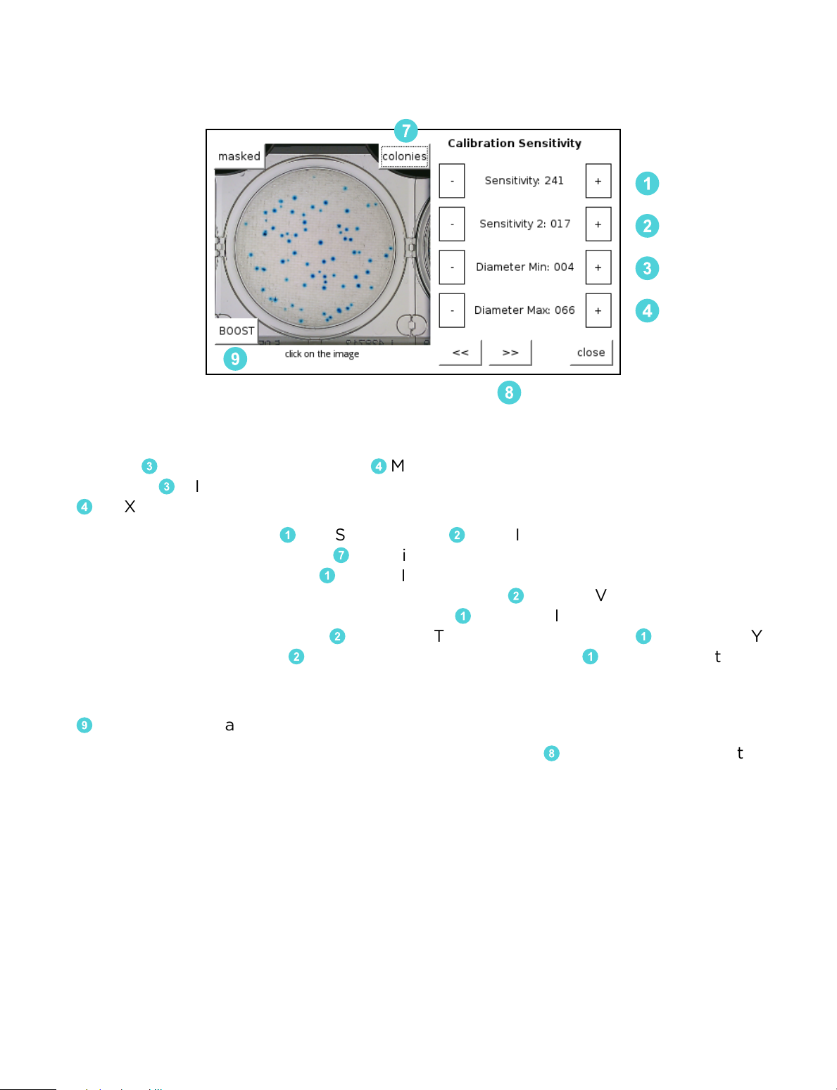
Procedure: Adjust the SENSITIVITY and the Diameter until all colonies are
detected and highlighted in the COLONIES VIEW.
7
1
2
3
4
9
8
STEPS FOR SENSITIVITY CALIBRATION
1. Set the 3 MIN DIAMETER to 2 and 4 MAX DIAMETER to 50 to start the process.
Raise the 3 MIN DIAMETER to exclude smaller objects if desired. Likewise, lower
4
MAX DIAMETER to exclude larger objects as needed.
2. Increase / Decrease the 1 SENSITIVITY and 2 SENSITIVITY 2 until all the colonies
are highlighted. Make sure the 7 Colonies button is active, otherwise the colonies
will not become highlighted. 1 SENSITIVITY is the primary function for controlling
sensitivity and the threshold of the algorithm while 2 SENSITIVITY 2 may be considered fine tuning of sensitivity. The higher the 1 SENSITIVITY the more objects the
unit will detect. The lower the 2 SENSITIVITY 2 the more sensitive 1 SENSITIVITY
becomes. The higher the 2 SENSITIVITY 2 the less sensitive 1 SENSITIVITY tuning
becomes.
3. To calibrate enhanced sensitivity for smaller pinpoint and fainter colonies, press the
9
BOOST button and repeat steps 1 and 2 as needed.
4. When all of the objects of interest are detected use the 8 FORWARD ARROW to
move to the next calibration screen. At any time the operator can exit the menu. The
updated settings can be saved or discarded when you close the menu.
Technical Support: 800-266-2222, option 2
19
Page 22
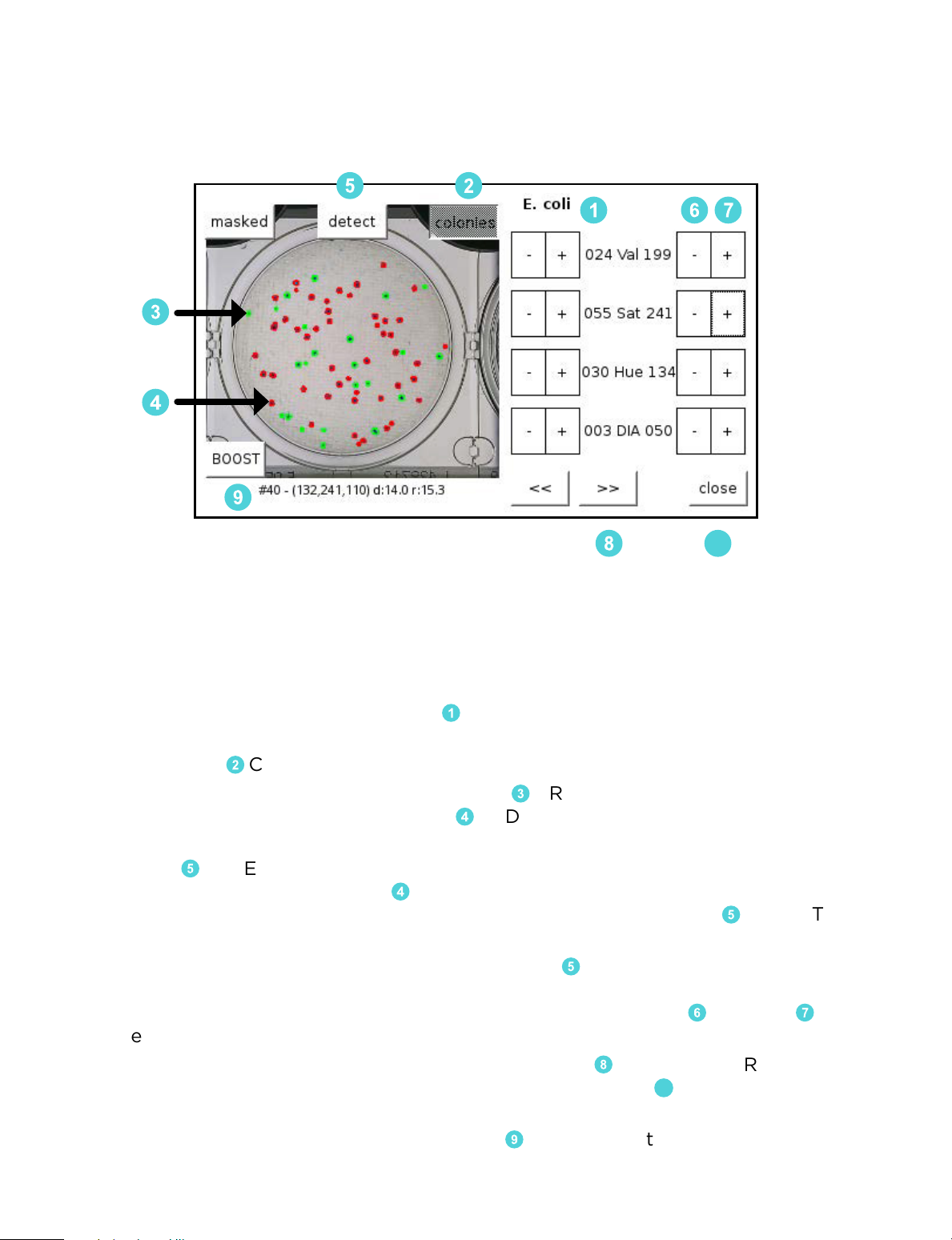
COLONY TYPE Screen
The second and sometimes third step of the calibration process is configuring the
unit to count the correct colonies based on their color and size.
5
2
1
76
3
4
9
Overview
The second and third steps of the calibration configure the unit to count the correct
colonies based on their Values, Saturation, Hue and Diameter.
8
10
STEPS FOR COLONY TYPE CALIBRATION
1. Make sure you are calibrating for the 1 correct mode. The example above is for an
E. coli plate.
2. Make sure the 2 COLONIES VISUALIZATION is on.
3. Colonies that are counted are highlighted in 3 GREEN, colonies that are detected
but are not counted are highlighted in 4 RED. If colonies are not detected at all
then return to the Calibration Sensitivity Screen to update the Sensitivity Settings.
4. Press the 5 DETECT Button. Now touch a colony that should be counted that is
not counted, this colony will be 4 RED. This will adjust the settings to include the
touched colony. You can continue to touch RED colonies with the 5 DETECT mode
enabled until all required colonies are counted.
5. If you cannot obtain the correct settings with the 5 DETECT Function, turn the
function o and touch the colony that is not being detected. Review the Values,
Saturation, Hue and Diameter values of this colony. Adjust the 6 MIN and 7 MAX
ranges of the values to include the colony values.
6. When all the objects of interest are detected use the 8 FORWARD ARROW if there
is another colony type and repeat the process or touch the CLOSE Button.
Confirm the changes if the unit is reading correctly.
10
7. Repeat steps 1-6 as needed to calibrate the
20
9
BOOST function.
Page 23
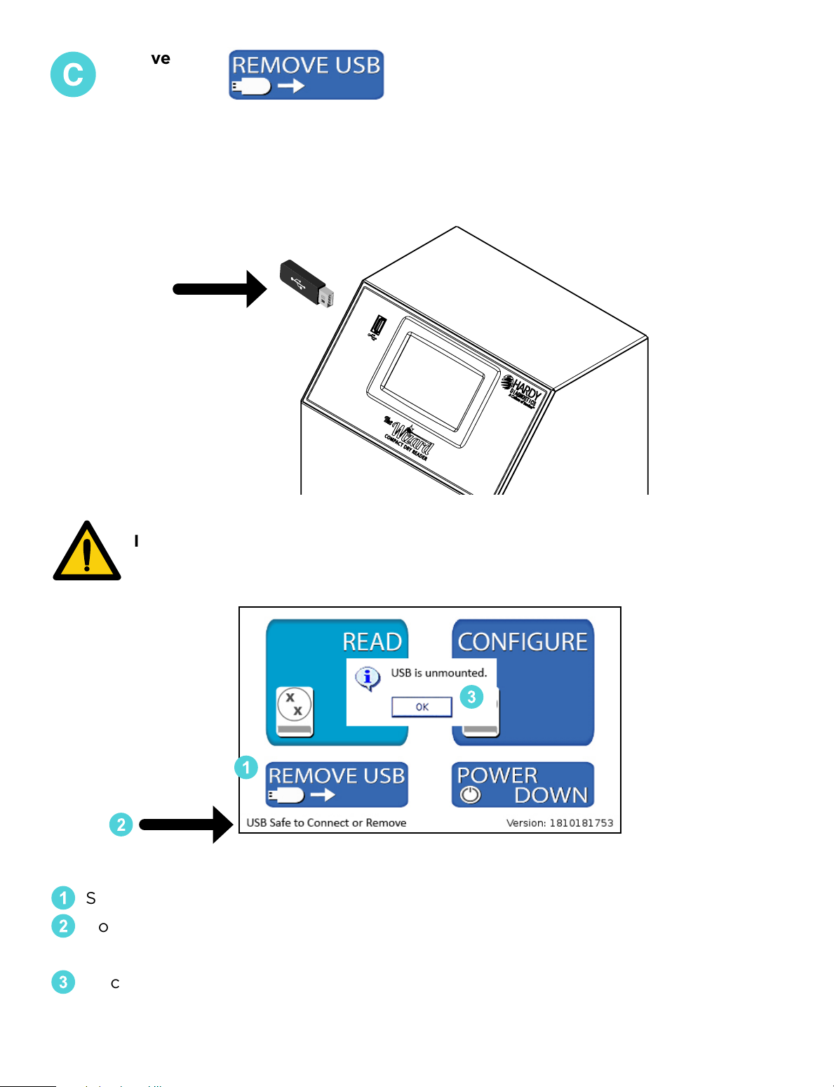
Remove USB
The Wizard™ CompactDry™ Reader does not store data directly on the unit. Data
will need to be stored using a USB thumb drive, or direct to a PC or LIMS option.
There are three USB ports available. The USB port located on the front of the machine is recommended for ease of access.
In order to prevent errors in data, please use the “Remove USB” function
located on the home screen to safely remove your USB device.
3
1
2
Select “Remove USB” from the Home Screen.
1
Confirm it is safe to remove the USB flash drive by checking the USB status in the
2
bottom left hand corner of the Home Screen.
Once status reads “USB is unmounted,” it is safe to remove your USB device.
3
Technical Support: 800-266-2222, option 2
21
Page 24
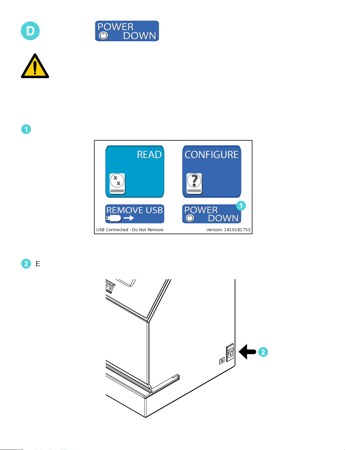
Power Down
Use the POWER DOWN button located on the Home Screen to safely
shut down the Control System.
Power down the Control System, using the POWER DOWN button.
1
1
Ensure all plates are removed and click power switch to the OFF position.
2
2
22
Page 25
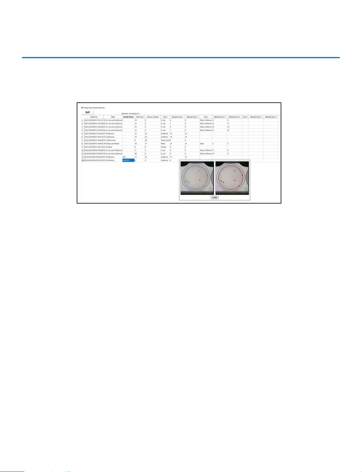
How to connect to the Hardy Data
Receiver Program
Users have the option of uploading the Hardy Data Receiver Program that comes on a
USB flash drive with The Wizard™ CompactDry™ Reader. This program will organize the
images and data collected by the The Wizard™ CompactDry™ Reader.
For instructions on using the Hardy Data Receiver Program, follow the directions
below:
What you’ll need to get started with the Hardy Data Receiver Program:
• Windows PC with wired Ethernet capability
• USB drive with “Hardy Data Receiver” file
• Ethernet switch
• USB to Ethernet adapter
• Ethernet Cables (x2)
Machine Requirements:
• PC running windows 8.1 or newer version
• Firmware setting to allow a database connection
How to upload the Hardy Data Receiver software:
• Connect your windows PC to the Ethernet switch using an Ethernet cable.
• Upload and save the “Data Receiver” file onto your PC from the provided
USB drive.
• Extract the content of the “data receiver” file to your PC.
• Open the unzipped “data receiver” file and double click the file named
“Hardy Data Receiver.” This will launch the program.
Technical Support: 800-266-2222, option 2
23
Page 26
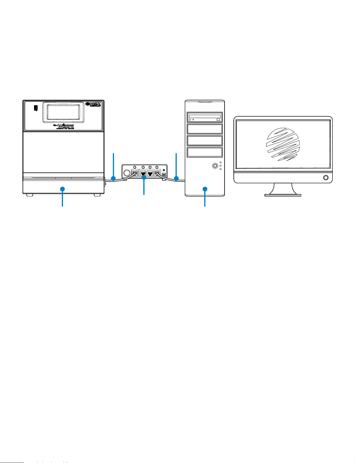
How to connect your The Wizard™ CompactDry™ Reader:
• Make sure your Wizard Reader is powered down.
• Connect the USB to Ethernet adapter to an available USB port on The Wizard™
CompactDry™ Reader.
• Insert Ethernet cable into the USB to Ethernet adapter.
• Plug the opposite end of the Ethernet cable into the Ethernet switch.
The Wizard™
CompactDry™ Reader.
Ethernet
Cable #1
Ethernet Switch
Ethernet
Cable #2
PC
24
Page 27
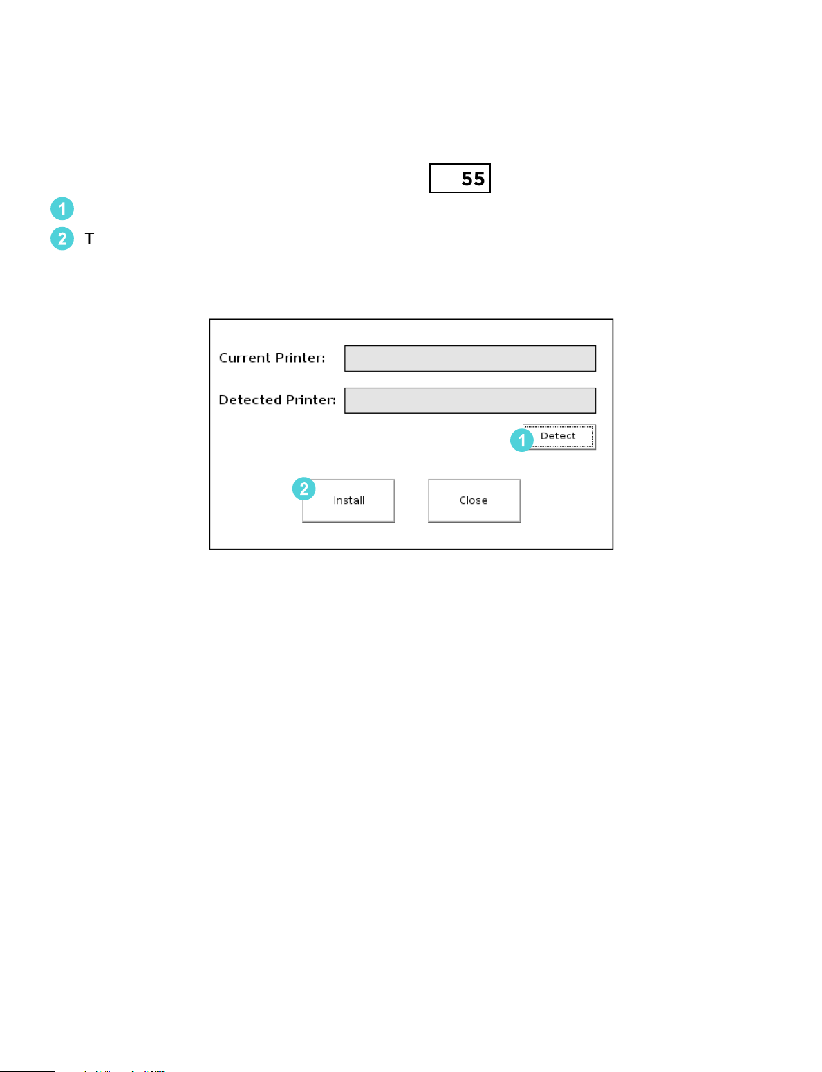
Connecting the USB Thermal Printer
• Connect the power cord and the USB cord to the printer.
• Connect the USB cord to
• Navigate to the CONNECTION CONFIGURATION from the Advanced Configure
Screen to configure the printer. Passcode
Touch DETECT to detect the printer.
1
Touch INSTALL to update the settings and connect to the printer. The printer will
2
now print the readout and images depending on the settings.
The Wizard™ CompactDry™ Reader and power on the unit.
0855
1
2
Technical Support: 800-266-2222, option 2
25
Page 28
Accessories
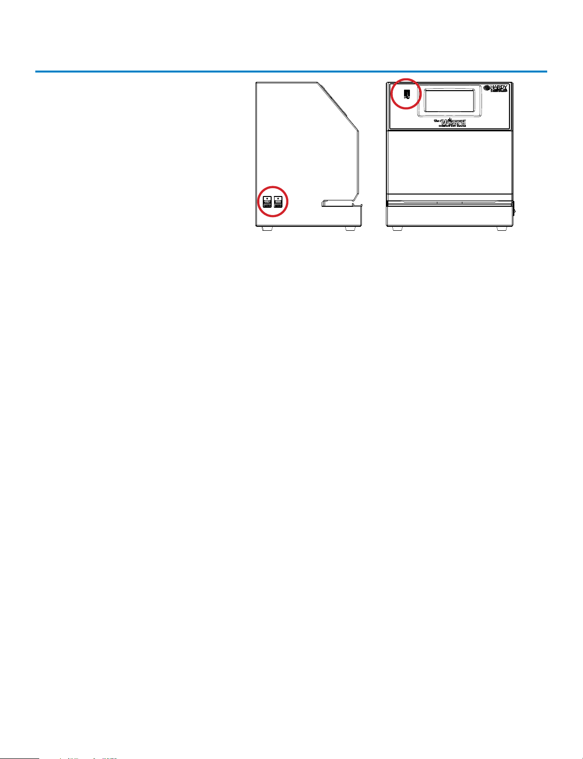
Accessories – The (3) USB ports
on the The Wizard™ CompactDry™
Reader can be used with the following devices:
A) USB Flash Drive (included) – The USB flash drive is used to save sample count
data and sample images.
B) USB Wireless Keyboard (sold separately) – The USB Wireless Keyboard is
used for quickly inputting sample (Cat. no. 120103).
C) USB Barcode Scanner (sold separately) – Barcoded samples can be scanned
with the barcode scanner to input the sample identification information. To
use the Barcode Scanner, scan the sample barcode when the unit prompts for
the sample name (Cat. no. 120102).
D) USB Thermal Printer (sold separately) – The USB Thermal Printer prints
sample count data and an image of the CompactDry™ plate (Cat. no. 120101).
26
Page 29

Limitations
The Wizard™ CompactDry™ Reader can be configured to identify pinpoint colonies;
however, debris may interfere with the identification of colonies of equal size, so sample filtration using a filter bag is highly recommended prior to plating.
The Wizard™ CompactDry™ Reader has been configured and validated with several hundred food samples and ATCC organisms. It is expected to detect most sample
types by its default settings. However, due to the high variability of sample types, labs
are strongly recommended to perform a validation of their samples and make settings
adjustments as directed in the manual to ensure that the unit performs optimally. Users
should be aware that the following limitations may aect the unit’s ability to accurately
read colonies:
• Debris
• Colony density, visibility, and size
• Background artifacts
• Incubation times
It is imperative that ground or blended samples are properly filtered to remove debris
that can mimic or mask the appearance of a colony. This can be easily accomplished by
using a membrane filter bag. In particular, pinpoint sized colonies can be configured in
the “BOOST” function to be accurately detected provided competing debris of equal
size and color aren’t present on the plate. It is recommended to use a stomacher and
filter homogenized sample afterwards, which will both help to eliminate carry-over of
tiny particles of sample onto the surface of the medium.
Sample plates should be diluted to achieve no more than 150CFU, which is the The
Wizard™ CompactDry™ Reader ’s limit of detection, and it is further recommended to
dilute to 100 CFU or less for optimal performance. Please refer to the Procedure
section of the IFU associated with the plate type that is being read on The Wizard™
CompactDry™ Reader.
Please refer to the Interpretation of results and the limitations sections of the IFU
associated with the plate type that is being read on The Wizard™ CompactDry™ Reader
to ensure colonies are properly detected. Plates should be read immediately after
recommended incubation times and allowed to incubate for the full recommended
times to ensure adequate colony size and color development. Excessive incubation
times may lead to the development of plate artifacts due to drying or color changes
that could lead to poor detection.
Technical Support: 800-266-2222, option 2
27
Page 30
Specifications
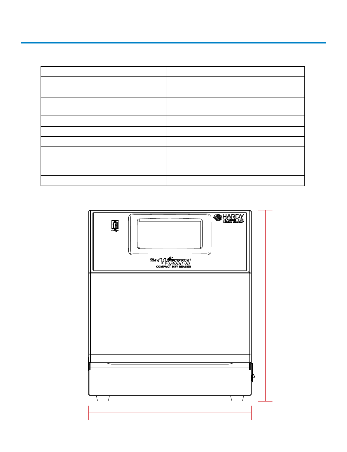
The Wizard™ CompactDry™ Reader Specifications
Part Code/Model # CDR1
Dimensions W x D x H 10” x 8” x 12”
Dimensions W x D x H 25.4cm x 20cm x 30cm
Reading Speed
Connections USB Type A x 3
Operation Temperature Range 10 °C to 30 °C
Power 12 Volts DC x 4 Amps
Electrical Approval 12 Volts DC x 4 Amps
Weight 25 lbs./ 11.34 kg
Approximately 5-6 seconds, dependent on the amount of colonies
Power Pack is UL, CSA,
CE approved
28
12”
10”
Page 31

Warranty and Service
Warranty
When used in laboratory conditions and according to these operating instruc-
tions, Hardy Diagnostics warrants this product to be free from defects due to
materials or workmanship for two (2) years from date of shipment. This warranty
will be void if product has been modified or disassembled. Warranty is limited to
repair or replacement, as deemed necessary by seller of product, including cost
of freight to and from seller’s repair location. Seller is not obligated to supply
product on loan to buyer or its customers under the warranty. The liability of
Hardy Diagnostics for any defective equipment during the warranty period shall
be limited to the repair of defective equipment or replacement thereof without
charge for shipping, parts, or labor.
Maintenance and Cleaning
The Wizard™ CompactDry™ Reader is designed to require minimal maintenance.
If the unit requires cleaning of the exterior, unplug the unit and use a lightly
dampened cloth to clean the metal areas. Use a nonabrasive cloth to clean the
touch screen area. DO NOT USE HARSH CLEANING AGENTS, such as bleach or
alcohol to clean any area of the equipment.
The best method to keep the interior area of the unit clean is to ensure that
CompactDry™ plates are dry and free of debris before placing them into the
unit. If the interior plate reading area of the unit requires cleaning, use a lint free
cloth and a tongue depressor. Wrap the lint free cloth around the stick and slide
through the unit. Do not force the item into the unit as it could damage the
plate indexing system. The cleaning stick and cloth should slide freely through
the plate bay. If this does not clean the plate reading area, dampen the cloth
with water and repeat the process.
Service
For all service needs contact:
Hardy Diagnostics Technical Services at
800-266-2222, option 2
or [email protected]
Technical Support: 800-266-2222, option 2
29
Page 32
Our Advantage
ardy Diagnostics manufactures over 2,700 prepared culture media products and
provides a complete selection of over 13,000 microbiology supply items. Founded
H
laboratories within the United States and throughout the world.
• Quality Control Program
All of the products manufactured by Hardy Diagnostics are tested to the highest standards
for quality and performance.
• ISO Certified
The Quality management system of the Hardy Diagnostics’ California and Ohio
manufacturing facilities has been certified to ISO 13485, a quality standard specifically
for medical device manufacturers.
• Custom Product Manufacturing
Hardy Diagnostics is willing and able to manufacture products specific to your needs.
Special container and formula requests are welcome. Simply contact your area Sales
Representative.
in 1980, Hardy Diagnostics has grown to service over 10,000 microbiology
• Two Manufacturing Plants
Hardy Diagnostics is the only culture media company with bi-coastal manufacturing
plants that provide our customers with the additional security of product availability. In
addition, nine distribution centers are strategically located throughout the United States.
061319jy
 Loading...