

Page 1
HI HLPS SERIES
LOAD POINT ASSEMBLIES
OPERATION AND INSTALLATION
MANUAL
Corporate Headquarters
9440 Carroll Park Drive, Suite 150
San Diego, CA 92121
Phone: (858) 278-2900
FAX: (858) 278-6700
Web-Site: http://www.hardysolutions.com
Hardy Process Solutions Document Number: 0596-0237-01 Rev G
Copyright 1999-2013 Hardy Process Solutions All Rights Reserved. Printed in the U.S.A. (941028)
Page 2

Local Field Service
Hardy has over 200 field technicians in the U.S., and more positioned throughout the
world to assist you in your support needs. We also have factory engineers who will
travel to your facility anywhere in the world to help you solve challenging applica
tions. We're ready to support you with:
• Installation and start-up
• Routine maintenance and certification
• Plant audits and performance measurement
• Emergency troubleshooting and repair
To request Emergency Service and Troubleshooting, Start-up, Installation, Calibration, Verification or to discuss a Maintenance Agreement please call 800-821-5831
Option 4 or Emergency Service after hours (Standard Hours 6:00 AM to 5:30 PM
Pacific Standard Time) and weekends 800-821-5831 Option 4.
-
Outside the U.S
Hardy Process Solutions has built a network of support throughout the globe. For specific field service options available in your area please contact your local sales agent
or our U.S. factory at +1 858-292-2710, Option 4.
Page 3

CAUTION: UNPACK WITH CARE
WHEN UNPACKING, DO NOT DISCARD THE PACKING CASE OR ANY PACKING MATERIAL, UNTIL THE
CONTENTS OF THE PACKING CASE ARE
INSPECTED AND CAREFULLY COMPARED WITH
THE SHIPPING DOCUMENTS.
IF ANYTHING IS UNSATISFACTORY, PLEASE
NOTIFY HARDY INSTRUMENTS IMMEDIATELY BY
CALLING, FAXING OR E-MAILING TO:
Customer Support Department
HARDYPROCESS SOLUTIONS
9440 Carroll Park Drive, Suite 150
San Diego, California 92121
Phone: (800) 821-5831
(858) 278-2900
FAX: (858) 278-6700
E-mail: hardysupport@hardysolutions.com
Web Address: www.hardysolutions.com
A RETURN AUTHORIZATION NUMBER IS REQUIRED
BEFORE RETURNING ANY DAMAGED PRODUCT.
CALL THE CUSTOMER SUPPORT DEPARTMENT TO
GET THE NUMBER. YOUR COMPANY NAME,
ADDRESS, TELEPHONE NUMBER, SERIAL NUMBER
OF THE UNIT AND A BRIEF DESCRIPTION OF THE
PROBLEM SHOULD BE READY WHEN CALLING.
IN CASE OF DAMAGE DUE TO SHIPPING, NOTIFY
THE DELIVERING CARRIER IMMEDIATELY FOR AN
INSPECTION.
Page 4

Page 5

Table of Contents
Table of Contents
General Information - - - - - - - - - - - - - - - - - - - - - - - - 1
Three Load Point Types - - - - - - - - - - - - - - - - - - - - - - 2
Unpacking - - - - - - - - - - - - - - - - - - - - - - - - - - - - - 3
Installation of the Ground Strap - - - - - - - - - - - - - - - - - - - 3
Site Preparation - - - - - - - - - - - - - - - - - - - - - - - - - - 5
Precautions - - - - - - - - - - - - - - - - - - - - - - - - - - - - 5
Basic Engineering Principles for Positioning Load Point Assemblies - 5
Principle #1 - - - - - - - - - - - - - - - - - - - - - - - - - - 5
Principle #2 - - - - - - - - - - - - - - - - - - - - - - - - - - 5
Principle #3 - - - - - - - - - - - - - - - - - - - - - - - - - - 5
Principle #4 - - - - - - - - - - - - - - - - - - - - - - - - - - 6
Typical Mounting Arrangements - - - - - - - - - - - - - - - - - - 6
Round Vessel with 3 Load Point Assemblies 7
Round Vessel with 3 Load Point Assemblies - Angle Config. #1 - 7
Round Vessel with 3 Load Point Assemblies - Angle Config. #2 - 8
Square Hopper with 3 Load Point Assemblies - Even
Load Distribution - - - - - - - - - - - - - - - - - - - - - - - 8
Square Hopper with 3 Load Point Assemblies - Uneven
Load Distribution - - - - - - - - - - - - - - - - - - - - - - - 9
Round Vessel with 4 Load Point Assemblies - - - - - - - - - - 9
Typical 4 - Load Point Assembly Installation - - - - - - - - - - 10
Typical 6 - Load Point Assembly Installation - - - - - - - - - - 11
Level Requirements - - - - - - - - - - - - - - - - - - - - - - - - 11
Stiffness - - - - - - - - - - - - - - - - - - - - - - - - - - - - - - 11
Installation Procedures - - - - - - - - - - - - - - - - - - - - - - - 12
Pre-Installation Procedures - - - - - - - - - - - - - - - - - - - 12
Installing Load Point Assemblies with Anchor Bolts - - - - - - - 13
Installing the Base Plate - - - - - - - - - - - - - - - - 13
Installing the Top Plate to the Load Surface - - - - - - 18
Adjusting the Anti-Lift Off Device - - - - - - - - - - - - - - - - - 21
Replacing the Load Sensor - - - - - - - - - - - - - - - - - - - - - 21
Troubleshooting - - - - - - - - - - - - - - - - - - - - - - - - - - 25
Physical Checks - - - - - - - - - - - - - - - - - - - - - - - - 25
Electrical Tests for Load Point Assembly Problems - - - - - - - 25
Zero Balance Test - - - - - - - - - - - - - - - - - - - 25
Bridge Resistance Test - - - - - - - - - - - - - - - - 26
Resistance to Ground Test - - - - - - - - - - - - - - - 26
Electrical Termination Cable Color Codes - - - - - - - - - - - - - - 27
Model Numbers - - - - - - - - - - - - - - - - - - - - - - - - - - 28
Three Leg Systems - - - - - - - - - - - - - - - - - - - - - - 28
Four Leg Systems - - - - - - - - - - - - - - - - - - - - - - - 29
Specifications - - - - - - - - - - - - - - - - - - - - - - - - - - - 29
i
Page 6

HI HLPS SERIES LOAD POINT ASSEMBLY
ii
Page 7

OPERATION AND INSTALLATION MANUAL
Congratulations, on your purchase of the Hardy Process Solutions
Load Point Assembly. This product, is engineered to set a new standard in load point assemblies. Hardy combined new innovations with
previously extra cost features and just plain common sense features
and provided you with optimum performance unequaled anywhere.
General Information The Hardy HI HLPS Hermetic Load Point System
provides accurate output in the most demanding
applications. The load sensor performance exceeds
IP68 and NEMA 6 Standards for Wash Down Resis
tance.
Use the HI HLPS Free Sliding Load Point System for
medium capacity vessels. The pre-assembled Free
Sliding Load Point System consists of three low pro
file mount types (See Figs. 1,2,3) that are designed to
eliminate the effects of unwanted forces and resulting
in exceptional load measuring accuracy.
Each load point consists of a stainless steel load sensor which is hermetically sealed (gauge area and cable
entry), Enhanced C2
tion, matched mV/V and mV/V/Ohm and a 1/4 inch
conduit adapter. The load points are pre-assembled at
our factory, eliminating any assembly in th e field.
Each load point is fitted with a grounding strap and
anti-lift-off protection. The load points mounting
hardware is available in either stainless or galvanized
steel.
®
Second Generation Calibra-
-
-
Page 1
Page 8
HI HLPS SERIES LOAD POINT ASSEMBLY
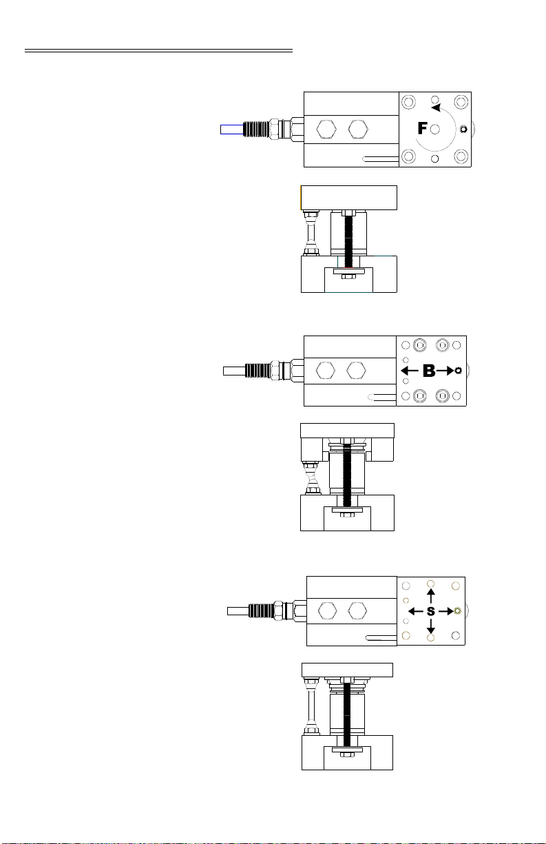
Three Load Point Types
FIG. 1: FIXED PIN LOAD POINT
Page 2
FIG. 2: BUMPER PIN LOAD POINT
FIG. 3: FREE SLIDING PIN LOAD POINT
Page 9

OPERATION AND INSTALLATION MANUAL
Unpacking • Do not remove the load point assembly from it’s
packaging until just before installation. Although
the load sensor is designed for harsh environ
ments, it is a precision instrument and should be
treated as such.
• Inspect the box, packing and the load point
assembly for any signs of damage that might
occur during shipment. Since almost all of the
load point assemblies are shipped F.O.B. our fac
tory, such damage is normally the responsibility
of the carrier and should be reported to them.
• LOAD SENSOR CERTIFICATION SHEETS
ARE AVAILABLE 24 HOURS A DA Y IN
THE SUPPORT SECTION OF OUR WEB
SITE: http://www.hardysolutions.com
• Write down the serial number(s) on the inside of
the back cover for reference when talking to
Hardy Customer Service. Store this information
in a secure dry location for future reference.
-
-
-
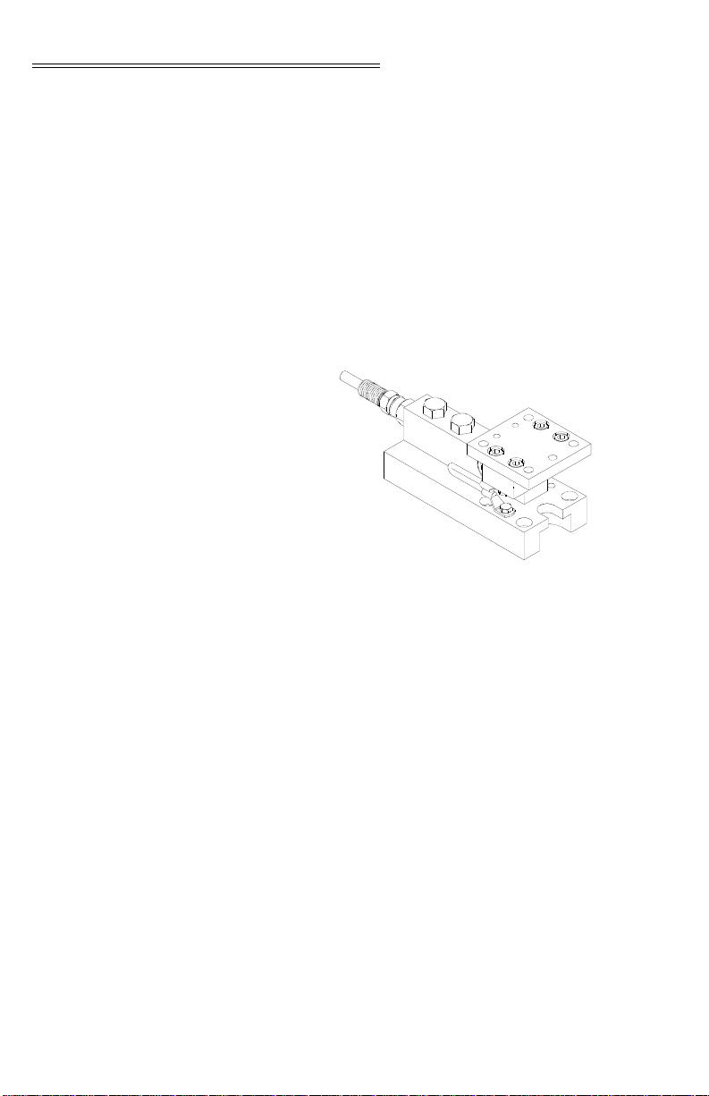
Installation of the Ground Strap
Step 1. Cut the plastic strap that fastens the
ground strap to the Load Point Assembly.
Step 2. Use a box-end wrench to remove the two
shipping brackets from the load point. (See
Fig. 4)
FIG. 4: REMOVING SHIPPING BRACKETS
Step 3. Remove the shipping brackets, which are
intended only for use during shipment
from the factory. They offer no protection
Page 3
Page 10
HI HLPS SERIES LOAD POINT ASSEMBLY
if you are shipping the vessel fully
assembled on the load points.
Step 4. Save the two shortest machine screws (the
hex bolts that fasten the shipping brackets
to the base plate). You will use them to
install the ground strap. (See Fig. 1-4)
Step 5. Place one of the ground strap connectors
over the threaded hole in the base plate.
These are the ones that fastened the ship
ping bracket to the base. (See Fig. 5)
-
FIG. 5: GROUND STRAP INSTALLED
Step 6. Install a hex bolt. Tighten with a box-end
wrench.
Step 7. Place the other ground strap connector
over the threaded hole in the top plate.
Step 8. Install the other hex bolt. Tighten with a
box-end wrench.
Step 9. Fig. 5 shows the ground strap installed on
the left side when facing the front of the
load point assembly. However, you can
install the strap on either side if necessary.
NOTE: Do not connect the ground strap to the base plate on
the right side and to the top plate on the left side or
vice versa. Crossing over will interfere with the load
cell performance.
Page 4
Page 11

OPERATION AND INSTALLATION MANUAL
Site Preparation • All mounting surfaces for the base and loading
plate must be level. The distance between the
mounting surface of the loading plate and base
must be within 1/32” of the nominal height, “H”.
The Load Point Assemblies in a system must be
level to within +/- 0.5
• When mounting the base plate on concrete, use
grout to level the plate.
• Do any welding before installing the load points.
• Provide proper drainage to prevent the load point
assembly from standing in water.
Precautions • Always treat the Load Sensor as a precision
instrument. Leave the load point assembly in its
packaging until it is time for installation.
• NEVER CARRY OR SWING THE LOAD SENSORS BY THEIR CABLES.
• Never allow moisture to get into any int erconnections.
• HARDY SOLUTIONS RECOMMENDS THAT
YOU DO NOT CUT YOUR ADVANTAGE
OR ADVANTAGE LITE® LOAD SEN
o
.
®
SOR CABLE. BECAUSE YOUR C2®
ACCURACY WILL BE AFFECTED AND
THE WARRANTY VOIDED.
Basic Engineering Principles for Positioning Load Point Assemblies
Principle #1 • Position the Load Points Assemblies so that the
load (weight) is distributed as evenly as possible
between each load point assembly in the scale.
• When the installation does not allow even distribution of the load, select higher capacity load
point assemblies.
NOTE: All load point assemblies must have the same capacity
when used in one scale.
Page 5
Page 12

HI HLPS SERIES LOAD POINT ASSEMBLY
Principle #2 • All scales should include one fixed pin-load
mount (F), one bumper pin-load mount (B). All
other load point assemblies in a scale must be the
free-sliding mount (S).
Principle #3 • Place the fixed pin-load mount and the bumper
pin load mount as far as possible from each other .
• The fixed pin load mount and the bumper pin
load mount must be mounted in the same longitu
dinal axis.
• In applications that use three load points it is
sometimes difficult to mount the fixed-pin and
bumper load mounts in-line. Therefore the fixed
pin and bumper load mounts can be positioned at
o
a 45
angle from each other and 45o from the
free-pin load mount. See the mounting diagrams
below for more information.
Principle #4 • If possible, the fixed-pin load mount should be
installed so that the load mount is oriented in the
direction of travel (e.g. when under a conveyor,
the load mount must be in the same longitudinal
axis with the direction of the travel of the con
veyor). The load mount must be oriented in the
direction of any prevalent side force.
-
-
Typical Mounting Arrangements
NOTE: You can orient the load point assemblies to meet your
system installation requirements. All load point
o
assemblies can be rotated 360
in 90o increments. The
examples above are recommendations only. The only
requir ed orientation is that the bumper load cell must
point either towards or directly away from the fixed
load point.
Use the load cell cable for the pointer to ensure that
the vessel cannot rotate and allow the cells to slide off
their mounts.
Page 6
Page 13

Round Vessel with 3
F
S
B
<45
o
Load Point
Assemblies
Round Vessel with 3 Load Point Assemblies - Angle Config. #1
OPERATION AND INSTALLATION MANUAL
FIG. 6: THREE LOAD CELLS IN ROUND
CONFIGURATION
FIG. 7: ANGLE FOR FIXED AND BUMPER LOAD
CELLS IN ROUND CONFIGURATION
Page 7
Page 14

HI HLPS SERIES LOAD POINT ASSEMBLY
F
S
B
O
Round Vessel with 3 Load Point Assemblies - Angle Config. #2
FIG. 8: ANGLE FOR ALL LOAD CELLS IN ROUND
CONFIGURATION
NOTE: Load Cells can be oriented with cables pointed either
in or out. For three load point systems, the mounting
locations should be spaced120 degrees apart. For
four load point systems the mounting locations should
be spaced 90 degrees apart.
Square Hopper with 3 Load Point Assemblies - Even Load Distribution
Page 8
FIG. 9: ANGLE FOR FIXED AND BUMPER LOAD
CELLS IN SQUARE CONFIGURATION
Page 15

OPERATION AND INSTALLATION MANUAL
F
S
B
Square Hopper with 3 Load Point Assemblies - Uneven Load Distribution
FIG. 10: ANGLE FOR THREE LOAD CELLS IN
SQUARE CONFIGURATION
NOTE: This configuration is an exception to the even load
distribution principle. Use this configuration in cir
cumstances where you arrange several hopperin close
proximity to each other.
-
Round Vessel with 4 Load Point Assemblies
FIG. 11: FOUR LOAD CELLS IN ROUND
CONFIGURATION
Page 9
Page 16

HI HLPS SERIES LOAD POINT ASSEMBLY
FIG. 12: FOUR LOAD CELLS FACING
INWARD IN ROUND CONFIGURATION
Typical 4 - Load Point Assembly Installation
Page 10
FIG. 13: FOUR LOAD CELLS POSITIONED IN
A RECTANGULAR CONFIGURATION
Page 17

OPERATION AND INSTALLATION MANUAL
Typical 6 - Load Point Assembly Installation
FIG. 14: SIX LOAD CELLS POSITIONED IN A
RECTANGULAR CONFIGURATION
NOTE: In case there is doubt concerning load point assembly
installation, contact your local Hardy Process Solu
tions dealer , Application Engineering Department, or
Customer Support Department for assistance.
You can orient the load point assemblies to meet your
system installation requirements. All load point
assemblies can be rotated 360
o
in 90o increments. The
examples above are recommendations only.
Level Requirements For scales that must meet NIST Class 3 (OIML Class
3) specifications:
1. The base plate support surfaces must be
within 0.2 degrees (0.4mm/100mm)
2. The top plate support surfaces in the load
carrier must be within 0.5 degrees (0.9mm/
100mm)
For scales with accuracy requirements => 0.1%
1. The base plate support surfaces must be
within 0.4 degrees (0.08mm/100 mm)
2. T op plate support surfaces in the load carrier
must be within 1 degree (1.8mm/100mm)
Stiffness Load variations and external forces can cause support
surface level variations.
Page 11
Page 18

HI HLPS SERIES LOAD POINT ASSEMBLY
For scales that must meet NIST Class 3 (OIML Class
3) specifications:
1. Maximum base plate angle variation: 0.2
degrees.
2. Maximum top plate angle variation 0.5
degrees.
For scales that must meet accuracy specifications =>
0.1%
1. Maximum base plate angle variation 0.2
degrees
2. Maximum top plate angle variation 1 degree.
Installation Procedures
Pre-Installation Procedures
Step 1. Position the base plates with load cells on
the support surfaces and line them up in
accordance with the basic principles for
positioning. (See Principle #2, pg. 6)
Step 2. We recommend scribing or marking a cen-
terline on the top plate. (See Fig. 15)
FIG. 15: MARKING TOP PLATE FOR
INSTALLATION
Page 12
Page 19

OPERATION AND INSTALLATION MANUAL
Installing Load Point Assemblies with Anchor Bolts
Installing the Base Plate
The outline drawing located on the
www.hardysolutions.com Web Site provide the Base
Plate and Top Plate dimensions for the Load Point
Assembly. They include the thru hole diameters and
center distances.
Step 1. Make sure that the concrete foundation is
level.
Step 2. To assist in the installation of the anchor
bolts we recommend creating a template
using the thru hole diameters of the top
plate mounting dimensions. For drilling
dimensions, see the drawings accessed
from the Products page on the Hardy
Process Solutions web site. Note that the
holes for top and bottom are in direct
alignment, but the thickness of the top and
bottom plates differ.
Fig. 16 and Table 1 provide side dimensions and hole
diameters only.
Page 13
Page 20

HI HLPS SERIES LOAD POINT ASSEMBLY
Page 14
FIG. 16: BASE AND TOP PLATE DRAWINGS
TABLE 1: BASE & TOP PLATE DIMENSIONS
Page 21

OPERATION AND INSTALLATION MANUAL
FIG. 17: ANCHOR BOLTS TEMPLATE
Step 3. Use wood or metal to create the templates.
The size of the template depends on the
size of the anchor bolts.
Step 4. Mark a point on on each template. Then,
using the I/I diagram, make another mark
on the template measuring from the thru
hole center points on the base plate.
Step 5. Drill the thru holes the same size as the
base plate thru holes at each of the marks
you made on the templates.
Step 6. On the vessel or structural support that
will rest on the load point assemblies,
measure from the point where you want to
position the center of the fixed-pin load
point assembly’s top plate to where you
want the centers of the top plates of the
other load point assemblies used in the
weighing system. As you mark each cen
ter point location, check the typical mounting arrangements for load point systems
above.
Step 7. Place the center of the Anchor Bolt pattern
at the exact centers as measured in Step 6.
You can use the templates to assist in
locating these center points.
Page 15
-
Page 22

HI HLPS SERIES LOAD POINT ASSEMBLY
Step 8. When you place the anchor bolts into the
concrete foundation, slip the templates
over the anchor bolts so that the bolt center
distances will be the same as the base plate
thru holes of the load cell. You can leave
the templates there until after the concrete
drys or remove them when you think the
concrete has set to the point where the
anchor bolts won’t move.
Step 9. Allow room to install the jacking nuts and
washers. Yo u are going to make the level
adjustments with the jacking nuts. (See
Fig. 18)
Page 16
FIG. 18: INSTALLING THE FOUR ANCHOR
BOLTS FOR THE BASE PLATE
Step 10. Install the jacking nuts onto the anchor
bolts so there is about 1/2 inch between the
concrete foundation and the jacking nuts.
Don’t worry about level at this point, you
will level everything after the Load Point
Assembly/base plate is installed.
Step 11. Install four flat washers on each anchor
bolt above the jacking nuts. (See Fig. 17)
Step 12. Slide the load point assembly/base plate
onto the anchor bolts. You can install the
load point assemblies in one of four orien
tations. (See Fig. 19)
-
Page 23

OPERATION AND INSTALLATION MANUAL
FIG. 19: LOAD POINT ASSEMBLIES ORIEN-
TATION
This illustration uses the fixed load point
assembly, but you can do the same with
any of the load point assembly types.
Step 13. Use a bubble level to level the load point
assembly from side to side and corner to
corner. Use a box end wrench to adjust
each of the jacking nuts until each load
point assembly in the system is level.
Step 14. Install the base plate nuts finger tight. You
may need to adjust the jacking nuts later as
you install the rest of the load point assem
blies for the weighing system.
Step 15. If you replaced a loading pin or load cell,
make sure you grease the sliding and
fixed pins and the fixed pin housings in the
top plate and the load cell. Clean the stain
less plate on the under side of the top plate
and verify that the stainless plate is free of
scratches or other damage. Replace the
Stainless plate if scratched or damaged.
Step 16. Install the rest of the load point assemblies
according to the Positioning Principles.
(See Principles, pgs. 6 & 7)
-
-
NOTE: Load variations and external forces can cause sup-
port surface level variations.
Page 17
Page 24

HI HLPS SERIES LOAD POINT ASSEMBLY
Step 17. Level all the installed load point assem-
blies and adjust them according to the following base plate level requirements:
Installing the
Top Plate to
the Load
Surface
WARNING UNDER NO CIRCUMSTANCES MUST WELD-
Step 1. Disconnect the power to the controller to
which the load cells are connected.
Step 2. Disconnect all wires to the Summing Junc-
tion Box.
Step 3. You should have scribed or marked a cen-
terline on the top surface of the top plate to
locate the center. (See Fig. 6)
Step 4. Mark the point you want the center of the
top plate to be located on the support
bracket. Place the top plate center over the
support bracket mark and:
ING CURRENT BE ALLOWED TO PASS
THROUGH THE LOAD SENSOR. TO DO SO
WILL DESTROY THE LOAD SENSOR AND
COULD POSSIBLY CAUSE PERSONAL
INJURY AND/OR PROPERTY DAMAGE.
• Be sure to shield the entire load cell and
cable from any slag that might drop.
• Tack weld the top plate to the support
bracket.
• If you want to fasten the top plate to the
support bracket, use a marker or scribe
and trace the thru hole pattern of the top
plate on the support bracket. Drill four
thru holes or drill and tap four holes for
the fasteners. Install the top plate to the
support bracket using the four fasteners.
Page 18
Step 5. With the top plates installed, put the vessel
support bracket with the top plate onto the
pins of the load cells. The sliding load cell
pins must be riding on the stainless plate.
Make sure that the fixed pin is centered in
the top plate housing. The horizontal posi
tion is not critical, but the vertical position
-
Page 25

OPERATION AND INSTALLATION MANUAL
is. Use the C dimensions to determine the
proper height between the support surface
and the top of the top plate. (See Fig. 20)
Step 6. Level all the installed load point assem-
blies and make adjustments according to
the following top plate level requirements:
FIG. 20: HEIGHT DIMENSION C
MODEL # HEIGHT C
HI HLPS 1125, 2.25K,4.5K 3.54
HI HLPS 11.25K 4.72
HI HLPS 22.5K 6.69
(90)
(120)
(170)
TABLE 2: HEIGHT DIMENSION C
Step 7. To adjust the level of the top plate, use
shim stock between the top plate and the
support bracket. (See Fig. 21)
Page 19
Page 26

HI HLPS SERIES LOAD POINT ASSEMBLY
FIG . 21: ADJUSTING FOR LEVEL WITH SHIM
Step 8. If you tack welded the top plate to the sup-
port bracket, lift the vessel off the load cell
pins if you can) and finish welding the top
plate to the support bracket. If you cannot,
be sure to shield the entire load cell and
cable from any slag that might drop.
Lower the vessel back onto the sliding
loading pins.
STOCK
WARNING UNDER NO CIRCUMSTANCES MUST WELD-
ING CURRENT BE ALLOWED TO PASS
THROUGH THE LOAD SENSOR. TO DO SO
WILL DESTROY THE LOAD SENSOR AND
COULD POSSIBLY CAUSE PERSONAL
INJURY AND/OR PROPERTY DAMAGE.
Step 9. Pour grout up to the bottom surface of the
base plate and let dry.
CAUTION: DO NOT ALLOW GROUT TO COME IN CON-
TACT WITH THE ANTI-LIFT OFF DEVICE.
(SEE FIG. 13)
Page 20
Page 27

OPERATION AND INSTALLATION MANUAL
Adjusting the Anti-Lift Off Device
Replacing the Load Sensor
Step 1. Use a box end wrench to loosen the adjust-
ment hex nut that fastens the anti-lift-off
device to the top plate. (See Fig. 22)
FIG. 22: ANTI-LIFT OFF DEVICE
ADJUSTMENT
Step 2. Use a box-end wrench or your fingers to
adjust the hex screw until the gap between
the base plate and the washer are
between.0785” (2mm) and.1570” (4mm).
Step 3. Use a box-end wrench and tighten the
adjustment hex nut.
Step 1. Use a box-end wrench to loosen the nut
that fastens the anti-lift-off device to the
top plate. Remove the anti-lift-off device.
(See Fig. 14)
Step 2. Use a box-end wrench to remove the two
hex bolts that fasten the ground strap.
Remove the ground strap from the top
plate and the base plate.
Step 3. Jack up the vessel support leg and lift off
the top plate.
Step 4. Use a box-end or crescent wrench to
remove the two load sensor bolts that fas
ten the Load Sensor to the base plate. (See
Figs. 23 and 24)
Page 21
-
Page 28

HI HLPS SERIES LOAD POINT ASSEMBLY
FIG. 23: EXPLODED ISO VIEW OF FREE
SLIDING LOAD POINT ASSEMBLY
Page 22
FIG. 24: EXPLODED ISO VIEW OF BUMPER
LOAD POINT ASSEMBLY
Step 5. Remove the old load sensor.
Step 6. Align the load cell bolt thru holes with the
threaded base plate bolt holes.
Page 29

OPERATION AND INSTALLATION MANUAL
Step 7. Screw the two load cell bolts into the base
plate until they are finger tight only.
Step 8. The height (B) dimension is the minimum
required service area above the load cell
baseplate to remove the load cell bolts.
(See Fig. 24 & Table 3)
FIG. 25: B DIMENSION
MODEL # HEIGHT B
HI HLPS 1125, 2.25K,4.5K 2.91
(74.0)
HI HLPS 11.25K 4.02
(102)
HI HLPS 22.5K 5.83
(148)
TABLE 3: B DIMENSIONS
Step 9. Use a torque wrench and tighten the bolt
farthest from the cable end first. Then
tighten the bolt nearest the cable end.
Step 10. Again refer to the B dimensions. Use the
following torque values:
Page 23
Page 30

HI HLPS SERIES LOAD POINT ASSEMBLY
MODEL #
HI HLPS1125-43B
HI HLPS1125-43F
HI HLPS1125-43S
HI HLPS2.25K-43B
HI HLPS2.25K-43F
HI HLPS2.25K-43S
HI HLPS4.5K-43B
HI HLPS4.5K-43F
HI HLPS4.5K-43S
HI HLPS11.25K-43B
HI HLPS11.25K-43F
HI HLPS11.25K-43S
HI HLPS22.5K-43B
HI HLPS22.2K-43F
HI HLPS22.5K-43S
TABLE 4: LOAD CELL BOLT TORQUE
Foot pounds
(NewtonMeters
or Joules)
65 (88.5)
295 (400)
515 (700)
VALUES
Page 24
Step 11. Inspect the Stainless Plate for scratches or
damage. If there are scratches or damage:
• Use a box-end wrench to remove the
two hex machine screws that fasten the
stainless plate to the top plate. (See Fig.
24)
• Discard the old stainless plate.
• Place the new stainless plate so that the
thru holes are aligned with the threaded
holes in the top plate.
• Replace the two hex machine screws.
• Lower the vessel down onto the load
points.
• Reinstall the ground strap and anti-liftoff device. (See Figs. 23 & 24)
Page 31

OPERATION AND INSTALLATION MANUAL
Troubleshooting
Physical Checks Before doing any electrical tests do the following:
Step 1. Visually inspect each load point assembly
for physical damage. Look for distortions
or cracks in all metal parts.
Step 2. Check all welds to be sure they are not
cracked of have deep pot marks.
Step 3. Check all cables for cracks, cuts or crimp-
ing. Check for any abrasions on the cables.
Step 4. Look for structural changes in the scale or
supporting structures.
Step 5. Look for binding of any kind on the load
point assembly.
Step 6. Chapter 8, Page 8-2 of the Hardy Control-
ler Manual explains how to troubleshoot
using Integrated Technician. See: http://
www.hardysolutions.com for the support
page or contact your local Hardy Repre
sentative for information as to where to get
manuals for Hardy products.
-
Electrical Tests for Load Point Assembly Problems
Zero Balance Test
Step 7. Get the Load Sensor certification sheets
for referencing while troubleshooting. The
certifications are available to you 24 hours
a day on the support section of our Web
Site: http://www.hardysolutions.com.
If you find any of the problems stated above, replace
the part that is damaged.
Problem: Changes in the Zero Balance.
Cause: Load Cell has been overloaded.
Remedy:
Step 1. Use a millivolt meter or Integrated Techni-
cian feature (See Physical Checks, Step 6)
Page 25
Page 32

HI HLPS SERIES LOAD POINT ASSEMBLY
and measure the LPS output under “no
load” conditions. The reading should be
less than 1% of the full scale output.
NOTE: Sensors can shift up to about 10% of their full scale
and still function correctly.
Step 2. If the output has shifted more than 1%,
replace the sensor.
Assumption: A 5VDC excitation on a sensor with a
3mV/V output sensitivity, a 1% shift in zero balance
will yield a 0.1 mV/V change from the specification.
Bridge Resistance Test
Resistance to Ground Test
Problem: Changes in Bridge Resistance
Cause: Failure of a compensating element, or by a
broken or burned bridge wire. Often cause by an elec
trical transient such as lightning.
Remedy:
Step 1. Use an Ohmmeter and measure the resis-
tance between the EXC + and EXC- leads.
The value for the EXC leads should be
1106 ohms + - 5 ohms.
Step 2. Use an Ohmmeter and measure the resis-
tance between the SIG + and SIG - leads
The value for the SIG leads should be
1,000 ohms + - 1 ohm.
Step 3. Readings that exceed the ranges indicated
suggest damage and the load cell should
be throroughly inspected or replaced.
Problem: Electrical leakage is creating an unstable
output from the instrument.
Cause: W ater contamination in the load sensors or
cables.
Remedy:
-
Step 1. Tie together the load sensor excitation (2),
signal (2) and ground (1) wires.
NOTE: Be careful NOT to include the two C2 wires.
Page 26
Page 33

OPERATION AND INSTALLATION MANUAL
Step 2. Use a megohmmeter and measure the
resistance between all five wires tied
together and the load cell metal body.
• The measured value should be 5,000
megohms or more.
WARNING WHEN USING A MEGGER DO NOT EXCEED
50 VOLT RANGE.
• If the sensor fails this test remove the
ground wire and test with only the four
live leads.
• If the sensor passes the test an insulation
problem in the cable is most likely.
Step 3. Replace the load cell if the cell fails both
tests.
Electrical Termination Cable Color Codes
The cable is 6 conductor, shielded (floating) and 20
feet in length.
EXC+ Red
EXC - Black
SHIELD Yellow
C2+ Gray
C2- Violet
SIG + Green
SIG - White
Model Numbers
NOTE: The -43F/B/S indicates a stainless steel load sensor
with stainless steel mounting hardware. For galva
-
nized mounting hardware use -45 F/B/S
Capacity Model # Model # Model #
LBS Kn Fixed Assembly Bumper Assembly Slider Assembly
1,125 5 HI HLPS1125-43F HI HLPS1125-43B HI HLPS1125-43S
2.25K 10 HI HLPS2.25K-43B HI HLPS2.25K-43B HI HLPS2.25K-43S
TABLE 5: MODEL NUMBERS & CAPACITIES
Page 27
Page 34

HI HLPS SERIES LOAD POINT ASSEMBLY
Capacity Model # Model # Model #
LBS Kn Fixed Assembly Bumper Assembly Slider Assembly
4.5K 20 HI HL PS4.5K-43F HI HLPS4. 5K-43B HI HLPS4.5K-43S
11.25K 50 HI HLPS11.25K-43F HI HLPS11.25K-43B HI HLPS11.25K-43S
22.5K 100 HI HLPS22.5K-43F HI HLPS22.5K-43B HI HLPS22.5K-43S
TABLE 5: MODEL NUMBERS & CAPACITIES
Model #
Spare Load Sensor
HI SBH04-1125
HI SBH04-2.25K
HI SBH04-4.5K
HI SBH04-11.25K
HI SBH04-22.5K
Three Leg Systems
Page 28
TABLE 6: SPARE LOAD SENSORS
To tal Capacity
Model # Pounds Kn.
HI 3S3375-43 3.375k 15
HI 3S6.75K-43 6.75k 30
HI 3S13.5K-43 13.5k 60
HI 3S37.5K-43 33.75k 150
HI 3S67.5K-43 67.5k 300
TABLE 7: THREE LEG SYSTEMS
Page 35

OPERATION AND INSTALLATION MANUAL
Four Leg Systems
To tal Capacity
Model # Pounds Kn.
HI 4S4.5K-43 4.5k 20
HI 4S9K-43 9k 40
HI 4S18K-43 18k 80
HI 4S45K-43 45k 200
HI 4S90K-43 90k 400
TABLE 8: FOUR LEG SYSTEMS
Specifications
Operating Specifications
Rated Output (F.S.) - - - - - - - - - - - - - - - - - - - - - - - - - - - - - 2+-0.002mV
Non-Linearity- - - - - - - - - - - - - - - - - - - - - - - - - - - - - - - - - +-0.018% R.O.
Hysteresis - - - - - - - - - - - - - - - - - - - - - - - - - - - - - - - - - - - <-0.025% R.O.
Zero Balance - - - - - - - - - - - - - - - - - - - - - - - - - - - - - - - - - <+-1.0% R.O.
Creep @ 5 Min. - - - - - - - - - - - - - - - - - - - - - - - - - - - - - - - <+-0.02% R.O.
Temp Effect Output- - - - - - - - - - - - - - - - - - - - - - - - - - - - - <+-0.0012% R.O./C
Temp Effect Sensitivity - - - - - - - - - - - - - - - - - - - - - - - - - - <+-0.0010% R.O./C
Input Resistance - - - - - - - - - - - - - - - - - - - - - - - - - - - - - - - 1050 to 1200 ohms
Output Resistance - - - - - - - - - - - - - - - - - - - - - - - - - - - - - - 1000 +- 1 ohm
Insulation Resistance- - - - - - - - - - - - - - - - - - - - - - - - - - - - >5000 meg ohms
Excitation - - - - - - - - - - - - - - - - - - - - - - - - - - - - - - - - - - - 5-15VDC
Safe Load Limit - - - - - - - - - - - - - - - - - - - - - - - - - - - - - - - 200% Emax
Ultimate Load - - - - - - - - - - - - - - - - - - - - - - - - - - - - - - - - 300% Emax
Safe Side Load - - - - - - - - - - - - - - - - - - - - - - - - - - - - - - - - 100% Emax
Environmental Specifications
Operating Temperature - - - - - - - - - Minus 40o F to Plus176o F (-40o C to +80o C)
Compensated Temperature - - - - - - - 14o F to 104o F (Minus 10o C to Plus 40o C)
Load Sensor Material - - - - - - - - - - 17-4PH Martensitic (Magnetic) Stainless Steel
Load Sensor Fittings - - - - - - - - - - - Coated Tool Steel
Top Plate & Base Plate Material - - - 316 Stainless Steel or Galvanized Steel
Conduit Adapter - - - - - - - - - - - - - - .250-18 NPT
Page 29
Page 36

HI HLPS SERIES LOAD POINT ASSEMBLY
Hermetic Sealing
Gauging Area - - - - - - - - - - - Welded Cylindrical Sleeve
Cable Entry- - - - - - - - - - - - - Glass to Metal Header
Page 30
Page 37

OPERATION AND INSTALLATION MANUAL
Print the unit serial number and model number for reference when ordering
parts for the HI HLPS Load Point Assembly
The serial number can be found on the side of the load sensor, or by entering the
SelfTest Mode.
Scale Name/Location:
Model Number:
Serial Number 1:
Serial Number 2:
Serial Number 3:
Serial Number 4:
Serial Number 5:
Serial Number 6:
Serial Number 7:
Serial Number 8:
Page 31
Page 38

HI HLPS SERIES LOAD POINT ASSEMBLY
Page 32
 Loading...