

Page 1
HI HLPT SERIES
LOAD POINT ASSEMBLIES
OPERATION AND INSTALLATION
MANUAL
Corporate Headquarters
9440 Carroll Park Drive, Ste. 150
San Diego, CA 92121
Phone: (858) 278-2900
FAX: (858) 278-6700
Web-Site: http://www.hardysolutions.com
Hardy Process Solutions Document Number: 0596-0239-01 Rev F
Copyright 2012 Hardy Process Solutions, Inc. All Rights Reserved. Printed in the U.S.A. (941028)
Page 2
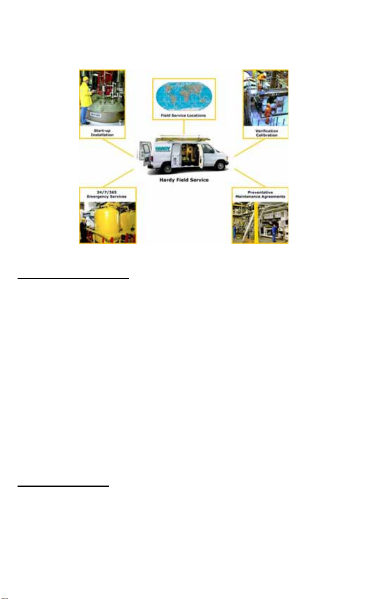
Local Field Service
Hardy has over 200 field technicians in the U.S., and more positioned throughout the
world to assist you in your support needs. We also have factory engineers who will
travel to your facility anywhere in the world to help you solve challenging applications. We're ready to support you with:
• Installation and
• Routine maintenance and certification
• Plant audits and performance
• Emergency tr
To request Emergency Service and Troubleshooting, Start-up, Installation, Calibration, Verification or to discuss a Maintenance
Option 3 or Emergency Service after hours (Standard Hours 6:00 AM to 6:00 PM
Pacific Standard Time) and weekends
start-up
measurement
oubleshooting and repair
Agreement please call 800-821-5831
Ext. 1111.
Outside the U.S
Hardy Instruments has built a network of support throughout the globe. For specific
field service options available in your area please contact your local sales agent or our
U.S. factory at +1 858-292-2710.
1-2
Page 3

Page 4

Table of Contents
Table of Contents - - - - - - - - - - - - - - - - - - - - i
General Information - - - - - - - - - - - - - - - - - - - - - -1
Unpacking - - - - - - - - - - - - - - - - - - - - - - - - - - -1
Site Preparation - - - - - - - - - - - - - - - - - - - - - - - -2
Precautions - - - - - - - - - - - - - - - - - - - - - - - - - -2
Basic Engineering Principles for Positioning Load Poin t
Assemblies - - - - - - - - - - - - - - - - - - - - - - - - -2
Typical Mounting Arrangements - - - - - - - - - - - - - - - -3
Load Sensor Orientation - - - - - - - - - - - - - - - - - -3
Round Vessel with 1 Load Point - - - - - - - - - - - - - -3
Round Vessel with 3 Load Poin
Safety Rods - - - - - - - - - - - - - - - - - - - - - - - -4
Round Vessel with 4 Load Poin
Replacing the Load Sensor - - - - - - - - - - - - - - - - - - -5
Removing the Load Sensor - - - - - - - - - - - - - - - -6
Installing a New Load Sensor - - - - - - - - - - - - - - -6
Troubleshooting - - - - - - - - - - - - - - - - - - - - - - - -7
Physical Checks - - - - - - - - - - - - - - - - - - - - - -7
Electrical Tests for Load Point Assembly Problems - - - - -8
Zero Balance Test - - - - - - - - - - - - - - - - - - -8
Bridge Resistance Test - - - - - - - - - - - - - - - -9
Resistance to Ground Test - - - - - - - - - - - - - - -9
Electrical Termination Cable Color Codes - - - - - - - - - - - -10
Model Numbers - - - - - - - - - - - - - - - - - - - - - - - -11
Three Leg Systems - - - - - - - - - - - - - - - - - - - -11
Four Leg Systems - - - - - - - - - - - - - - - - - - - - -12
Specifications - - - - - - - - - - - - - - - - - - - - - - - - -12
t Assemblies - - - - - - - -4
t Assemblies - - - - - - - -5
i
Page 5

1-ii
Page 6

CAUTION: UNPACK WITH CARE
WHEN UNPACKING, DO NOT DISCARD THE PACKING CASE OR ANY PACKING MATERIAL, UNTIL THE
CONTENT
INSPECTED AND CAREFULLY COMPARED WITH
THE SHIPPING DOCUMENTS.
S OF THE PACKING CASE ARE
IF ANYTHING IS UNSATISFACTORY
NOTIFY HARDY IMMEDIATELY BY CALLING, FAXING OR E-MAILING TO:
Customer Support Department
HARDY PROCESS SOLU
9440 Carroll Park Drive, Ste. 150
San Diego, California 92121
Phone: (800) 821-5831
(858) 278-2900
FAX: (858) 278-6700
E-mail: support@hardysolutions.com
Web Address: www.hardysolutions.com
A RETURN AUTHORIZATION NUMBER IS REQUIRED
BEFORE
CALL THE CUSTOMER SUPPORT DEPARTMENT TO
GET THE NUMBER. YOUR COMPANY NAME,
ADDRESS, TELEPHONE NUMBER, SERIAL NUMBER
OF THE UNIT AND A BRIEF DESCRIPTION OF THE
PROBLEM SHOULD BE READY WHEN CALLING.
RETURNING ANY DAMAGED PRODUCT.
TIONS, INC.
, PLEASE
IN CASE OF DAMAGE DUE TO SHIPPING, NOTIFY
DELIVERING CARRIER IMMEDIATELY FOR AN
THE
INSPECTION.
Page 7

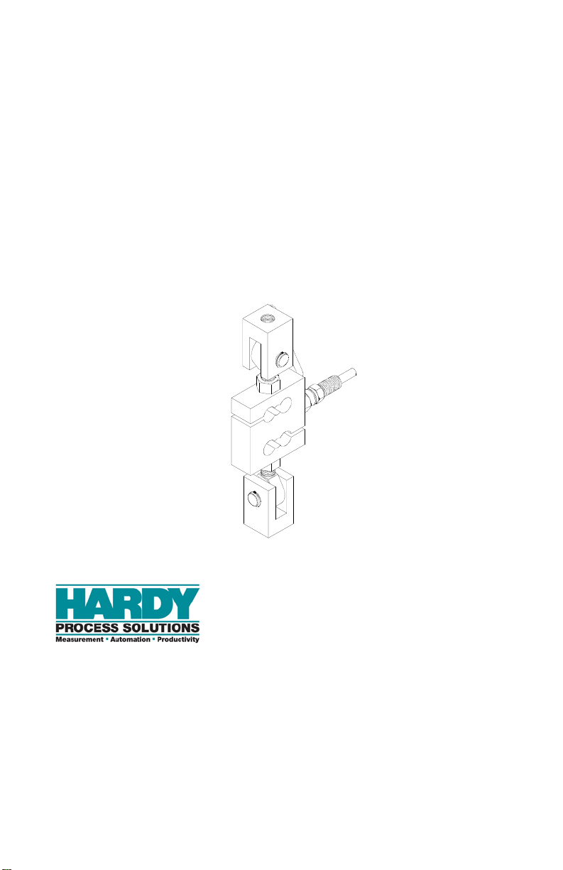
OPERATION AND INSTALLATION MANUAL
Congratulations, on your purchase of the Hardy Advantage Load
Point Assembly. This product, is engineered to set a new standard in
load point assemblies. Hardy combined new innovations with previously extra cost features and just plain common sense features and
provided you with optimum performance unequaled anywhere.
General Information The Hardy HI HLPT Hermetic Load Point System is
designed to provide accurate output in the most
demanding applications. The load sensor performance
exceeds IP68 and NEMA 6 Standards for Wash Down
Resistance.
The HI HLPT Advantage, Tension Load Point Systems are designed for use on low to medium capacity
vessels. The pre assembled Tension Load Point System is specifically designed to eliminate the effects of
unwanted forces resulting in exceptional load measuring accuracy.
Each load point consists of a stainless steel load sensor which is truly hermetically sealed (gauge area and
cable entry), Enhanced C2® Second Generation Calibration, matched mV/V and mV/V/Ohm and a 1/4
inch conduit adapter. The load points are pre assembled at our factory eliminating any assembly in the
field. Each load point is fitted with a grounding strap.
The load points mounting hardware is available in
either stainless or galvanized steel and consist of two
(2) clevises, two (2) Clevis Pins with four (4) external
retaining rings and two (2) rod end assemblies.
Unpacking • Do not remove the load point assembly from it’s
packaging until just before installation. Although
the load sensor is designed for harsh environments, it is a precision instrument and should be
treated as such.
• Inspect the box, packing and the load point
assembly for any signs of damage that might
occur during shipment. Since almost all of the
load point assemblies are shipped F.O.B. our fac-
Page 1
Page 8

HI HLPT SERIES LOAD POINT ASSEMBLY
tory, such damage is normally the responsibility
of the carrier and should be reported to them.
• LOAD SENSOR CERTIFICATION SHEETS
ARE AVAILABLE 24 HOURS A DAY AT
OUR WEBSITE: http://www.hardysolutions.com
• Write down the serial number(s) on the inside of
the back cover for reference when talking to
Hardy Customer Service. Store this information
in a secure dry location for future reference.
Site Preparation • All mounting surfaces for the base and loading
plate must be level. The Load Point Assemblies
in a system must be level to within +/- 0.5o.
• Any welding should be done prior to installation
of the load points.
Precautions • Always treat the Load Sensor as a precision
instrument. Leave the load point assembly in its
packaging until it is time for installation.
• NEVER CARRY OR SWING THE LOAD SENSORS BY THEIR CABLE.
• Never allow moisture to get into any interconnections.
Basic Engineering Principles for Positioning Load Point Assemblies
Page 2
• Load Points Assemblies should be positioned
such that the load (weight) is distributed as
evenly as possible between each load point
assembly in the scale.
• When the installation does not allow even distribution of the load, select higher capacity load
point assemblies. This does not effect the weighing accuracy of the scale.
• All load point assemblies must have the same
capacity when used in one scale.
Page 9

Typical Mounting Arrangements
Load Sensor Orientation
Round Vessel with 1 Load Point
OPERATION AND INSTALLATION MANUAL
FIG. 1: LOAD SENSOR ORIENTATION
FIG. 2: ROUND VESSEL WITH 1 LOAD POINT
ASSEMBLY
Page 3
Page 10

HI HLPT SERIES LOAD POINT ASSEMBLY
Round Vessel with 3 Load Point Assemblies
FIG. 3: VERTICAL TANK - 3 LOAD CELLS
Safety Rods
FIG. 4: SPACE REQUIRED FOR SAFETY
RODS
CAUTION: THE ORIENTATION OF THE TOP AND BOT-
TOM CLEVIS ASSEMBLY MUST BE AT 90° AS
SHOWN IN FIG. 4. IMPROPER ORIENTATION CAUSES THE CLEVISES TO MISALIGN.
THIS CAN LEAD TO BINDING WHICH CAN
Page 4
Page 11

Round Vessel with 4 Load Point Assemblies
OPERATION AND INSTALLATION MANUAL
CAUSE THE EYE END OF THE EYE BOLTS
TO SHEAR AND/OR PRODUCE AN INACCURATE WEIGHT READING.
FIG. 5: 4 LOAD POINT ASSEMBLY
NOTE: In case there is some doubt concerning load point
assembly installation, contact your local Hardy Representative, Hardy Process Solutions, Application
Engineering or Customer Support Department for
assistance.
Replacing the Load Sensor
NOTE: Make sure that the rod ends are threading into the
threaded holes smoothly and easily before final
assembly.
Page 5
Page 12

HI HLPT SERIES LOAD POINT ASSEMBLY
The type of installation will govern the method of
locating, attaching and assembling the parts of a load
point. The following is a typical installation:
Removing the Load Sensor
Installing a New Load Sensor
Step 1. Check to be sure you have all the parts.
Step 2. Take the load off the load cell.
Step 3. Use a flat screw driver and push the retain-
ing rings off the clevis pin on both clevis
mounts. (See Fig. 6)
Step 4. Pull the two clevis pins out of the clevises
and ball joints. (See Fig. 6)
Step 5. Slide the load sensor with the rod ends out
of the clevis mounts.
Step 6. Use a box end or crescent wrench and
loosen the lock nuts on both rod ends that
are fastened to the load sensor. (See Fig. 6)
Step 7. Use a small piece of masking tape or chalk
to mark the location of the lock nuts for re-
assembly.
Step 8. Use channel locks to loosen the rod ends.
Step 9. Remove both rod ends from the load cell.
Step 1. Get a new load sensor.
Step 2. Replace the rod ends and tighten with
channel locks to the mark made by the
masking tape or the chalk.
Step 3. Remove the masking tape or wipe off the
chalk.
Step 4. Tighten the lock nut.
Step 5. Insert the ball joint of one of the rod ends
between the jaws of the clevis mounting
block. (See Fig. 6)
Step 6. Align the holes in the ball joint with the
holes in the clevis.
Step 7. Slide the clevis pin through the clevis and
the ball joint holes.
Step 8. Insert the retaining rings in the grooves on
both sides of the clevis pin until the ring
snaps onto the pin.
Step 9. Repeat Step 5 through Step 8 for the other
clevis mounting block.
Step 10. Put the load back on the load point assem-
bly.
Page 6
Page 13

OPERATION AND INSTALLATION MANUAL
FIG. 6: ISO ASSEMBLY DRAWING
Troubleshooting
Physical Checks Before doing any electrical tests do the following:
Step 1. Visually inspect each load point assembly
for physical damage. Look for distortions
or cracks in all metal parts.
Step 2. Check all welds to be sure they are not
cracked of have deep pot marks.
Page 7
Page 14

HI HLPT SERIES LOAD POINT ASSEMBLY
Step 3. Check all cables for cracks, cuts or crimp-
ing. Check for any abrasions on the cables.
Step 4. Look for structural changes in the scale or
supporting structures.
Step 5. Look for binding of any kind on the load
point assembly.
Step 6. Refer to your Hardy Manual for informa-
tion on how to troubleshoot using Inte-
grated Technician. For your convenience
this manual is available on the Hardy Web
site at: http://www.hardyinst.com on the
support page. If you do not have access to
the internet, contact your local Hardy Rep-
resentative for information as to where to
get this and other manuals for Hardy prod-
ucts.
Step 7. Get the Load Sensor certification sheets
for referencing while troubleshooting. The
certifications are available to you 24 hours
a day at our Web Site: http://www.hardy-
inst.com
If you find any of the problems stated above, replace
the part that is damaged.
Electrical Tests for Load Point Assembly Problems
Zero Balance Test
NOTE: Sensors can shift up to about 10% of their full scale
Page 8
Problem: Changes in the Zero Balance.
Cause: Load Cell has been overloaded.
Remedy:
Step 1. Use a millivolt meter or the Integrated
Technician feature of the HI 2151/30WC
(See Physical Checks, Step 6) and measure
the LPS output under “no load” condi-
tions. The reading should be less than 1%
of the full scale output.
and still function correctly.
Page 15

OPERATION AND INSTALLATION MANUAL
Step 2. If the output has shifted more than 10%,
replace the sensor.
Assumption: A 5VDC excitation on a sensor with a
3mV/V output sensitivity, a 1% shift in zero balance
will yield a.1mV/V change from the specification.
Bridge Resistance Test
Resistance to Ground Test
Problem: Changes in Bridge Resistance
Cause: Failure of a compensating element, or by a
broken or burned bridge wire. Often cause by an electrical transient such as lightning.
Remedy:
Step 1. Use an Ohmmeter and measure the resis-
tance between the EXC + and EXC- leads.
• The value for the EXC leads
should be 1106 ohms + - 5
ohms.
Step 2. Use an Ohmmeter and measure the resis-
tance between the SIG + and SIG - leads.
• The value for the SIG leads
should be 1,000 ohms + - 1
ohm.
Step 3. Readings that exceed the ranges indicated
suggest damage and the load cell should
be throroughly inspected or replaced.
Problem:Electrical leakage is creating an
unstable output from the instrument.
Cause: Water contamination in the load
sensors or cables.
Remedy:
Step 1. Tie together the load sensor excitation (2),
signal (2) and ground (1) wires.
NOTE: Be careful NOT to include the two C2 wires.
Page 9
Page 16

HI HLPT SERIES LOAD POINT ASSEMBLY
Step 2. Use a megohmmeter and measure the
resistance between all five wires tied
together and the load cell metal body.
• The measured value should be
5,000 megohms or more.
WARNING WHEN USING A MEGGER DO NOT EXCEED
50 VOLT RANGE.
• If the sensor fails this test
remove the ground wire and
test with only the four live
leads.
• If the sensor passes the test an
insulation problem in the cable
is most likely.
Step 3. Replace the load cell if the cell fails both
tests.
Electrical Termination Cable Color Codes
WARNING LOAD CELL CABLE LENGTH HAS BEEN
Page 10
The cable is 6 conductor, shielded (floating) and 20
feet in length.
EXC+ Red
EXC - Black
SIG + Green
SIG - White
C2+ Gray
C2- Violet
SHIELD Yellow
CALCULATED INTO C2 CALIBRATION
DATA. HARDY PROCESS SOLUTIONS RECOMMENDS THAT YOU DO NOT CUT YOUR
ADVANTAGE OR ADVANTAGE LITE LOAD
SENSOR CABLE, AS YOUR C2 ACCURACY
WILL BE AFFECTED AND THE WARRANTY
WILL BE VOIDED.
Page 17

OPERATION AND INSTALLATION MANUAL
Model Numbers
NOTE: The -43C indicates a stainless steel load sensor with
stainless steel mounting hardware. For galvanized
mounting hardware use -45 C
Capacity Model # Model #
LBS Kn Fixed Assembly Spare Load Sensor
225 1 HI HLPT225-43C HI STH06-225
450 2 HI HLPT450-43C HI STH06-450
1,125 5 HI HLPT1125-43C HI STH06-112K
2.25K 10 HI HLPT2.25K-43C HI STH01-2.25K
4.5K 20 HI HLPT4.5K-43C HI STH01-4.5K
11.25 50 HI HLPT11.25K-45C HI STH01-11.25K
TABLE 1: MODEL NUMBERS & CAPACITIES
Three Leg Systems
Total Capacity
Model # Pounds Kn
HI 3T675-43 675 3
HI 3T1.35K-43 1.35K 6
HI 3T3375-43 3.375K 15
HI 3T6.75K-43 6.75KK 30
HI 3T13.3K-43 13.5K 60
HI 3T33.75K-45 33.75K 150
TABLE 2: THREE LEG SYSTEMS
Page 11
Page 18

HI HLPT SERIES LOAD POINT ASSEMBLY
Four Leg Systems
Total Capacity
Model # Pounds Kn
HI 4T900-43 900 4
HI 4T1.8K-43 1.8K 8
HI 4T4.5K-43 4.5K 20
HI 4T9K-43 9K 40
HI 4T18K-43 18K 80
HI 4T45K-45 45K 200
TABLE 3: FOUR LEG SYSTEMS
Specifications
Operating Specifications
Rated Output (F.S.) - - - - - - - - - - - - - - - - - - - - - - - - - - - - - 2+-0.002mV
Non-Linearity- - - - - - - - - - - - - - - - - - - - - - - - - - - - - - - - - +-0.018% R.O.
Hysteresis - - - - - - - - - - - - - - - - - - - - - - - - - - - - - - - - - - - <+-0.025% R.O.
Zero Balance - - - - - - - - - - - - - - - - - - - - - - - - - - - - - - - - - <+-1.0% R.O.
Creep @ 5 Min. - - - - - - - - - - - - - - - - - - - - - - - - - - - - - - - <+-0.01% R.O.
Temp Effect Output- - - - - - - - - - - - - - - - - - - - - - - - - - - - - <+-0.0014% R.O./C
Temp Effect Sensitivity - - - - - - - - - - - - - - - - - - - - - - - - - - <+-0.0007% R.O./C
Input Resistance - - - - - - - - - - - - - - - - - - - - - - - - - - - - - - - 1050 to 1200 Ohms
Output Resistance - - - - - - - - - - - - - - - - - - - - - - - - - - - - - - 1000 +- 1 ohm
Insulation Resistance - - - - - - - - - - - - - - - - - - - - - - - - - - - - >5000 megohms
Excitation - - - - - - - - - - - - - - - - - - - - - - - - - - - - - - - - - - - 5-15VDC
Safe Load Limit - - - - - - - - - - - - - - - - - - - - - - - - - - - - - - - 200% Emax
Ultimate Load - - - - - - - - - - - - - - - - - - - - - - - - - - - - - - - - 300% Emax
Safe Side Load - - - - - - - - - - - - - - - - - - - - - - - - - - - - - - - - 100% Emax
Page 12
Page 19

Environmental Specifications
OPERATION AND INSTALLATION MANUAL
Operating Temperature - - - - - - - - - Minus 40
Compensated Temperature - - - - - - - 14
o
F to Plus176o F (-40o C to +80o C)
o
F to 104o F (Minus 10o C to Plus 40o C)
Load Sensor Material - - - - - - - - - - 17-4PH Martensitic (Magnetic) Stainless Steel
Load Sensor Fittings - - - - - - - - - - - Coated Tool Steel
Top Plate & Base Plate Material - - - 316 Stainless Steel or Galvanized Steel
Conduit Adapter - - - - - - - - - - - - - - .250-18 NPT
Hermetic Sealing
Gauging Area - - - - - - - - - - - Welded Cylindrical Sleeve
Cable Entry - - - - - - - - - - - - Glass to Metal Header
Page 13
Page 20

HI HLPT SERIES LOAD POINT ASSEMBLY
Please print the unit serial number and model number for reference
when ordering parts for the HI HLPT Load Point Assembly
The serial number can be found on the side of the load sensor, or by
entering the SelfTest Mode of the HI 2151/30WC.
Scale Name/Location:
Model Number:
Serial Number 1:
Serial Number 2:
Serial Number 3:
Serial Number 4:
Serial Number 5:
Serial Number 6:
Page 14
 Loading...