

Page 1
Weight Processor
HI 6300 Series
User’s Guide
Hardy Process Solutions Document Number: 0596-0328-01 REV B
Page 2
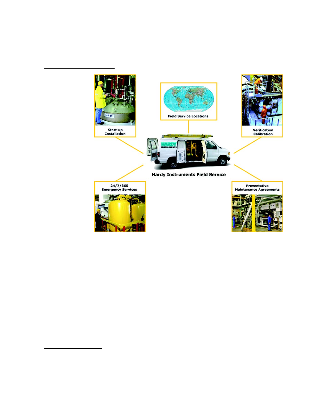
Local Field Service
Hardy has over 200 field technicians in the U.S., and more positioned throughout the world to
assist you in your support needs. We also have factory engineers who will travel to your facility
anywhere in the world to help you solve challenging applications. We're ready to support you with:
• Installation and start-up
• Routine maintenance and certification
• Plant audits and performance measurement
• Emergency troubleshooting and repair
To request Emergency Service and Troubleshooting, Start-up, Installation, Calibration, Verification
or to discuss a Maintenance Agreement please call 800-821-5831 or Emergency Service after hours
(Standard Hours 6:30 AM to 5:30 PM Pacific Standard Time) and weekends.
Outside the U.S
Hardy Process Solutions has built a network of support throughout the globe. For specific field service options available in your area please contact your local sales agent or our U.S. factory at
+1 858-292-2710.
Page 3

• • • • • •
Contents
Chapter 1 Overview- - - - - - - - - - - - - - - - - - - - - - - - - - - - - - - - - - 1
General Introduction to the HI 6300 Series Weight Processor - - - - - - - - - - 1
HI 6300 Series Weight Processor Description- - - - - - - - - - - - - - - - - - 1
Typical Applications - - - - - - - - - - - - - - - - - - - - - - - - - - - 2
Features and Capabilities - - - - - - - - - - - - - - - - - - - - - - - - - - - 2
Hardy Process Toolbox- - - - - - - - - - - - - - - - - - - - - - - - - - 2
C2® and eCal™ Calibration - - - - - - - - - - - - - - - - - - - - - - - 2
WAVERSAVER®- - - - - - - - - - - - - - - - - - - - - - - - - - - - 2
INTEGRATED TECHNICIAN® - - - - - - - - - - - - - - - - - - - - - 3
Weighing System Tests- - - - - - - - - - - - - - - - - - - - - - - - - - 3
Chapter 2 Specifications- - - - - - - - - - - - - - - - - - - - - - - - - - - - - - - - 5
Basic Specifications - - - - - - - - - - - - - - - - - - - - - - - - - - - - - - 5
General - - - - - - - - - - - - - - - - - - - - - - - - - - - - - - - - - 5
Number of Channels - - - - - - - - - - - - - - - - - - - - - - - 5
Update Rate - - - - - - - - - - - - - - - - - - - - - - - - - - - 5
Resolution - - - - - - - - - - - - - - - - - - - - - - - - - - - - 5
WAVERSAVER - - - - - - - - - - - - - - - - - - - - - - - - - 5
Averages - - - - - - - - - - - - - - - - - - - - - - - - - - - - 5
Input - - - - - - - - - - - - - - - - - - - - - - - - - - - - - - 5
Non-linearity - - - - - - - - - - - - - - - - - - - - - - - - - - 5
Common Mode Rejection - - - - - - - - - - - - - - - - - - - - 5
Common Mode Voltage Range - - - - - - - - - - - - - - - - - - 5
Front Panel (optional) - - - - - - - - - - - - - - - - - - - - - - 6
Load Cell Excitation - - - - - - - - - - - - - - - - - - - - - - - 6
C2 Calibration Input - - - - - - - - - - - - - - - - - - - - - - - 6
Cable Lengths - - - - - - - - - - - - - - - - - - - - - - - - - - 6
Network Connectivity - - - - - - - - - - - - - - - - - - - - - - - - - - 6
Environmental Requirements - - - - - - - - - - - - - - - - - - - - - - - 6
Operating Temperature Range - - - - - - - - - - - - - - - - - - 6
Temperature Coefficient - - - - - - - - - - - - - - - - - - - - - 6
Storage Temperature Range - - - - - - - - - - - - - - - - - - - 6
-40 to 85º C (-40º to 185º F) - - - - - - - - - - - - - - - - - - - 6
Humidity Range - - - - - - - - - - - - - - - - - - - - - - - - - 6
Maximum Altitude for Installation - - - - - - - - - - - - - - - - 6
Pending Approvals - - - - - - - - - - - - - - - - - - - - - - - - - - - - 6
Contents
i
•
•
•
•
•
•
Page 4

Chapter 3 HI 6300 Installation - - - - - - - - - - - - - - - - - - - - - - - - - - - - 7
Unpacking - - - - - - - - - - - - - - - - - - - - - - - - - - - - - - - - - - 7
Spare Parts List - - - - - - - - - - - - - - - - - - - - - - - - - - - - - - - - 8
Tool List - - - - - - - - - - - - - - - - - - - - - - - - - - - - - - - - - - - 8
Installing the HI 6300 Series Instrument - - - - - - - - - - - - - - - - - - - - 8
Installation options for the HI 6300 series instrument - - - - - - - - - - - 9
Mounting the Front Panel Display- - - - - - - - - - - - - - - - - 9
Panel Mount Option 1 - - - - - - - - - - - - - - - - - - - - - - - - - - 11
Panel Mount Option 2 - - - - - - - - - - - - - - - - - - - - - - - - - - 12
Making Longer Display Interface Cables - - - - - - - - - - - - - - - - - 13
DIN Rail Mount - - - - - - - - - - - - - - - - - - - - - - - - - - - - - 15
Wall Mount - - - - - - - - - - - - - - - - - - - - - - - - - - - - - - - 16
Remote Display Mount - - - - - - - - - - - - - - - - - - - - - - - - - - 18
Blind Unit (No display) - - - - - - - - - - - - - - - - - - - - - - - - - 19
Disassembly and Reassembly Notes and Cautions - - - - - - - - - - - - - 21
Load Cell Wiring Diagrams - - - - - - - - - - - - - - - - - - - - - - - - - - 22
Connecting to the Hardy HI 215IT or HI 6010/6020IT Summing Box - - - - 23
Chapter 4 Network Configuration- - - - - - - - - - - - - - - - - - - - - - - - - - - 25
Ethernet TCP/IP Network Configuration - - - - - - - - - - - - - - - - - - - - 25
LAN Connection - - - - - - - - - - - - - - - - - - - - - - - - - - - - - - - 26
DHCP Configuration Using the Front Panel - - - - - - - - - - - - 26
Direct Connect Hardware - - - - - - - - - - - - - - - - - - - - - 28
Windows PC Configuration- - - - - - - - - - - - - - - - - - - - 28
Windows 2000 - - - - - - - - - - - - - - - - - - - - - - - - - - 28
Windows XP- - - - - - - - - - - - - - - - - - - - - - - - - - - 29
Windows 7 - - - - - - - - - - - - - - - - - - - - - - - - - - - 29
Direct Connect Configuration - HI 6300 Series Instrument - - - - - - - - - 30
Ethernet-UDP - - - - - - - - - - - - - - - - - - - - - - - - - - - - - - 30
Modbus-RTU (over RS-485) - - - - - - - - - - - - - - - - - - - - - - - 31
Wiring Pinout - - - - - - - - - - - - - - - - - - - - - - - - - - 31
Modbus Setup - - - - - - - - - - - - - - - - - - - - - - - - - - 31
Modbus Functions - - - - - - - - - - - - - - - - - - - - - - - - 32
Modbus Registers - - - - - - - - - - - - - - - - - - - - - - - - 32
Network Command Interface - - - - - - - - - - - - - - - - - - - 32
Communications Parameters for the HI 6310 Only - - - - - - - - - - - - - - - 35
Printer (over RS-232) - - - - - - - - - - - - - - - - - - - - - - - - - - 35
USB Memory Stick - - - - - - - - - - - - - - - - - - - - - - - - - - - 36
Analog 4-20mA - - - - - - - - - - - - - - - - - - - - - - - - - - - - - 36
•
•
•
ii
Contents
•
•
•
Chapter 5 Instrument Configuration - - - - - - - - - - - - - - - - - - - - - - - - - 39
Using the Home Page to set Parameters - - - - - - - - - - - - - - - - - - - - 39
Page 5

Using the Front Panel Display Menus to Set Parameters - - - - - - - - - - - - - 40
Front Panel Display - - - - - - - - - - - - - - - - - - - - - - - - - - - 40
The Five Button Command Cluster - - - - - - - - - - - - - - - - - - - - 40
Using the Mode, Zero, and Tare buttons - - - - - - - - - - - - - - - - - - 41
Entering Numeric and Alphanumeric Values - - - - - - - - - - - 42
Commands and Parameters - - - - - - - - - - - - - - - - - - - - - - - - 44
Calibration Menu - - - - - - - - - - - - - - - - - - - - - - - - - - - - 45
C2 (eCal) Commands and Parameters - - - - - - - - - - - - - - - 45
Ref Weight Parameter - - - - - - - - - - - - - - - - - - - - - - 47
Sensitivity Parameter - - - - - - - - - - - - - - - - - - - - - - - 47
Hard Cal Commands and Parameters - - - - - - - - - - - - - - - - - - - 48
Cal Lo Weight Parameter - - - - - - - - - - - - - - - - - - - - 48
Cal Tolerance Parameter - - - - - - - - - - - - - - - - - - - - - 49
Span Weight Parameter- - - - - - - - - - - - - - - - - - - - - - 50
Cal Date Parameter- - - - - - - - - - - - - - - - - - - - - - - - 51
Communication Menu - - - - - - - - - - - - - - - - - - - - - - - - - - 51
HI 6310 Only - - - - - - - - - - - - - - - - - - - - - - - - - - 52
Ethernet TCP/IP Commands and Parameters- - - - - - - - - - - - 52
Enable DHCP Parameter - - - - - - - - - - - - - - - - - - - - - 52
Fixed IP Parameter - - - - - - - - - - - - - - - - - - - - - - - - 53
Mask Address Parameter - - - - - - - - - - - - - - - - - - - - - 54
Gateway Address Parameter - - - - - - - - - - - - - - - - - - - 54
DNS Server Parameter - - - - - - - - - - - - - - - - - - - - - - 54
Ethernet UDP Parameters- - - - - - - - - - - - - - - - - - - - - 54
Hardy Port Parameter - - - - - - - - - - - - - - - - - - - - - - 54
Modbus-RTU Commands and Parameters - - - - - - - - - - - - - - - - - 55
Slave Address Parameter - - - - - - - - - - - - - - - - - - - - - 55
Printer Command Parameters - - - - - - - - - - - - - - - - - - - - - - - 57
USB Memory Stick Parameters - - - - - - - - - - - - - - - - - - - - - - 58
4-20 mA Communications Commands and Parameters - - - - - - - - - - - 60
Weight Source Parameter - - - - - - - - - - - - - - - - - - - - - 60
Diagnostics Parameter Menu - - - - - - - - - - - - - - - - - - - - - - - - - 61
See the Chapter 9 for further information on Diagnostics. - - - - - - - - - 62
Display Parameter Menu - - - - - - - - - - - - - - - - - - - - - - - - - - - 62
Backlight Parameter - - - - - - - - - - - - - - - - - - - - - - - 62
Power Saving Parameters - - - - - - - - - - - - - - - - - - - - - 62
Auto Enable Parameter - - - - - - - - - - - - - - - - - - - - - - 62
Wait Time Parameter- - - - - - - - - - - - - - - - - - - - - - - 63
Set Background Parameter - - - - - - - - - - - - - - - - - - - - 63
Set Foreground Parameter - - - - - - - - - - - - - - - - - - - - 63
Split Screen Parameters and Commands- - - - - - - - - - - - - - - - - - 64
Filter Parameter Menu - - - - - - - - - - - - - - - - - - - - - - - - - - 66
NumAverages Parameter - - - - - - - - - - - - - - - - - - - - - 66
WAVERSAVER® Parameter- - - - - - - - - - - - - - - - - - - 67
Contents
•
•
•
iii
•
•
•
Page 6

Information Page- - - - - - - - - - - - - - - - - - - - - - - - - - - - - 68
Language Parameter Menu - - - - - - - - - - - - - - - - - - - - - - - - 68
Operations Parameter Menu - - - - - - - - - - - - - - - - - - - - - - - - - - 69
Tare Operations Commands and Parameters - - - - - - - - - - - - - - - - 69
Tare Amount Parameter - - - - - - - - - - - - - - - - - - - - - 69
Tare Offset Parameter - - - - - - - - - - - - - - - - - - - - - - 70
Tare Command - - - - - - - - - - - - - - - - - - - - - - - - - 71
Zero Operations Commands and Parameters- - - - - - - - - - - - - - - - 71
Zero Tolerance Parameter - - - - - - - - - - - - - - - - - - - - 71
Zero Amount Parameter - - - - - - - - - - - - - - - - - - - - - 71
Zero Command - - - - - - - - - - - - - - - - - - - - - - - - - 72
Auto Mode - - - - - - - - - - - - - - - - - - - - - - - - - - - - - - - 72
Count Operations Parameters and Commands - - - - - - - - - - - - - - - 72
Security Parameter Menu - - - - - - - - - - - - - - - - - - - - - - - - - - - 74
The Calibration Lock Parameters - - - - - - - - - - - - - - - - - - - - - 75
Calibration Lock Parameter - - - - - - - - - - - - - - - - - - - - 75
Calibration Password Parameter - - - - - - - - - - - - - - - - - 75
The Configuration Lock Parameters- - - - - - - - - - - - - - - - - - - - 76
Configuration Lock Parameter - - - - - - - - - - - - - - - - - - 76
Configuration Password Parameter - - - - - - - - - - - - - - - - 76
The Display Lock Parameters- - - - - - - - - - - - - - - - - - - - - - - 76
Display Lock Parameter - - - - - - - - - - - - - - - - - - - - - 76
Display Password Parameter - - - - - - - - - - - - - - - - - - - 77
The Keypad Lock Parameters- - - - - - - - - - - - - - - - - - - - - - - 77
Keypad Lock Parameter - - - - - - - - - - - - - - - - - - - - - 77
Keypad Password Parameter - - - - - - - - - - - - - - - - - - - 78
The Read Only Lock Parameters - - - - - - - - - - - - - - - - - - - - - 78
Read Only Lock Parameter - - - - - - - - - - - - - - - - - - - - 78
Read Only Password Parameter - - - - - - - - - - - - - - - - - - 78
Setup Parameter Menu - - - - - - - - - - - - - - - - - - - - - - - - - - - - 79
Capacity Parameter- - - - - - - - - - - - - - - - - - - - - - - - 79
Decimal Point Parameter - - - - - - - - - - - - - - - - - - - - - 79
Graduation Size Parameter - - - - - - - - - - - - - - - - - - - - 80
Instrument ID Parameter - - - - - - - - - - - - - - - - - - - - - 81
Motion Tolerance Parameter - - - - - - - - - - - - - - - - - - - 81
Operator ID Parameter - - - - - - - - - - - - - - - - - - - - - - 82
Unit (of Measure) Parameter - - - - - - - - - - - - - - - - - - - 82
•
•
•
iv
Contents
•
•
•
Chapter 6 Calibration- - - - - - - - - - - - - - - - - - - - - - - - - - - - - - - - - 85
Pre-Calibration Procedures - - - - - - - - - - - - - - - - - - - - - - - - - - 85
Electrical Check Procedures - - - - - - - - - - - - - - - - - - - - - - - - - - 86
Load Cell/Point Input/Output Measurements - - - - - - - - - - - - - - - 86
Load Check - - - - - - - - - - - - - - - - - - - - - - - - - - - - - - - 87
Page 7

C2 & eCAL Electronic Calibration- - - - - - - - - - - - - - - - - - - - - - - 87
Gravitation Correction - - - - - - - - - - - - - - - - - - - - - - - - - - 87
C2 and eCAL Calibration from the Web Page - - - - - - - - - - - - - - - 89
C2 Calibration from the Front Panel- - - - - - - - - - - - - - - - - - - - 90
Hard Calibration - - - - - - - - - - - - - - - - - - - - - - - - - - - - - - - 91
Hard Calibration from the Web page - - - - - - - - - - - - - - - - - - - 91
Hard Calibration from the Front Panel- - - - - - - - - - - - - - - - - - - 92
Chapter 7 Operation - - - - - - - - - - - - - - - - - - - - - - - - - - - - - - - - - 95
Getting Started - - - - - - - - - - - - - - - - - - - - - - - - - - - - - - - - 95
Mode Button- - - - - - - - - - - - - - - - - - - - - - - - - - - - - - - 95
Zero Operation- - - - - - - - - - - - - - - - - - - - - - - - - - - - - - 95
Tare Operation - - - - - - - - - - - - - - - - - - - - - - - - - - - - - 97
Auto Mode Tracking – Disabled (Default) - - - - - - - - - - - - - - - - 98
Auto Mode Tracking – Enabled - - - - - - - - - - - - - - - - - - - - - 98
Split Screen Mode - - - - - - - - - - - - - - - - - - - - - - - - - - - - 101
Making Longer Display Interface Cables - - - - - - - - - - - - - - - - - 101
Chapter 8 Security - - - - - - - - - - - - - - - - - - - - - - - - - - - - - - - - - - 105
Display Security Options - - - - - - - - - - - - - - - - - - - - - - - - - - - 105
The Display Lock - - - - - - - - - - - - - - - - - - - - - - - - - - - - - - - 106
The Keypad Lock - - - - - - - - - - - - - - - - - - - - - - - - - - - - - - - 108
The Configuration Lock - - - - - - - - - - - - - - - - - - - - - - - - - - - - 110
The Read Only, Security & Calibration Locks - - - - - - - - - - - - - - - - - 111
Modifying the Security Parameters- - - - - - - - - - - - - - - - - - - - - - - 112
Modifying the Calibration Parameters - - - - - - - - - - - - - - - - - - - - - 112
Modifying the Read Only Parameters - - - - - - - - - - - - - - - - - - - - - 113
Chapter 9 Troubleshooting - - - - - - - - - - - - - - - - - - - - - - - - - - - - - - - - - - - 115
Error Messages - - - - - - - - - - - - - - - - - - - - - - - - - - - - - - - - 116
Trouble Shooting Using Integrated Technician (IT®) - - - - - - - - - - - - - - 117
Stability Test ALL - - - - - - - - - - - - - - - - - - - - - - - - - - - - 117
PASS/FAIL and Stability Test - - - - - - - - - - - - - - - - - - - - - - 118
WAVERSAVER TEST - - - - - - - - - - - - - - - - - - - - - 118
Weight and Voltage ALL - - - - - - - - - - - - - - - - - - - - - - - - - - - 118
Weight - - - - - - - - - - - - - - - - - - - - - - - - - - - - - 118
RTZ (Return to Zero) Test - - - - - - - - - - - - - - - - - - - - - - - - 119
IT Test - - - - - - - - - - - - - - - - - - - - - - - - - - - - - - - - - 119
Sensor Number - - - - - - - - - - - - - - - - - - - - - - - - - 119
General Troubleshooting Flow Chart Index- - - - - - - - - - - - - - - - - - - 121
Contents
v
•
•
•
•
•
•
Page 8

A - Guideline Instability: Electrical and Mechanical review.- - - - - - - - - - - 122
A1. Checking for Unstable Components in a Weighing System - - - - - - - - - 123
B. Guidelines for Electrical, Mechanical or Configuration Issues - - - - - - - - 124
B1 - Guidelines to Verify Electrical Installation- - - - - - - - - - - - - - - - - 125
B2 - Guidelines to Verify Mechanical Installation - - - - - - - - - - - - - - - 126
B3 - Guidelines to Verify Configuration/Filter Settings to Improve Stability - - - 127
C - Integrated Technician and Stability Test Overview - - - - - - - - - - - - - 128
E Testing for Non-Return to Zero (System with IT Summing Card.) - - - - - - - 129
F. Verify Individual Load Sensor Millivolt Output readings - - - - - - - - - - - 130
G- Calibration Errors When Performing the Calibration - - - - - - - - - - - - - 131
H. Mechanical Installation - - - - - - - - - - - - - - - - - - - - - - - - - - - 132
J- Electrical Inspection - - - - - - - - - - - - - - - - - - - - - - - - - - - - 133
K - Installation Check Points - - - - - - - - - - - - - - - - - - - - - - - - - 134
M. Weight Processor’s Front Display is Blank or Locked - - - - - - - - - - - - 135
N. Analog Out (HI 6310 Only)- - - - - - - - - - - - - - - - - - - - - - - - - 136
Tests and Diagnostics - - - - - - - - - - - - - - - - - - - - - - - - - - - - - 137
Parameters- - - - - - - - - - - - - - - - - - - - - - - - - - - - - - - - 138
System and Load Cell Tests - - - - - - - - - - - - - - - - - - - - - - - - - - 139
Overview of Typical Load Cell System - - - - - - - - - - - - - - - - - - 139
INTEGRATED TECHNICIAN - - - - - - - - - - - - - - - - - - - - - - 140
Stability Test- - - - - - - - - - - - - - - - - - - - - - - - - - - 140
Weight and Voltage Tests - - - - - - - - - - - - - - - - - - - - 142
•
•
•
vi
Contents
•
•
•
Page 9

Chapter 1
• • • • • •
Overview
General Introduction to the HI 6300 Series Weight Processor
This Manual describes installation, setup and troubleshooting procedures for the HI 6300
Series Weight Processor. Be sure to read and understand all cautions, warnings, and safety
procedures in this manual to ensure safe operation and repair of this instrument.
Hardy Process Solutions sincerely appreciates your business. We encourage input about the
performance and operation of our products from our customers. Should you not understand
any information in this manual or experience any problems with this product, please contact
our Technical Support Department at:
Phone:
(858) 278-2900
Toll Free:
F AX:
1-800-821-5831
(858) 278-6700
E-Mail:
Or visit our web site at:
http://www.hardysolutions.com
Our web site provides information about our products and process weighing applications.
You can also update the HI 6300 User Guide. The latest revised manuals are available
FREE in the product selection pull down menu on our Web Site. Other pages on the site
provide answers to questions about weighing instruments, PLC plug in modules, load
points, summing boxes, process weighing or other Hardy Process Solutions products. Be
sure to sign up for the Hardy Newsletter to get the latest information on all Hardy products
and services. For answers to technical issues and service problems, check the Hardy
WebTech on our Hardy Web Site. Most problems can be resolved by the Hardy WebTech,
365 days a year, 24 hours a day 7 days a week. You can still contact a technician by phone
during our normal operating hours (6:30 AM to 5:30 PM Pacific Time) if necessary.
hardysupport@hardysolutions.com or hardyinfo@hardysolutions.com
HI 6300 Series Weight Processor Description
The HI 6300 series of single-channel weight processing instruments is suitable for
PLC-based or stand-alone weighing applications. The primary function of the
HI 6300 series is to provide stable gross or net weight in a variety of units such as oz,
lb, ton, gm, kg and mt.
Overview
•
•
1
•
•
•
•
Page 10

The HI 6300 series can be used with or without a display. The display is a bright 4.3”
high-contrast LCD capable of high-resolution graphics and discrete messaging. The
unit can be panel mounted, DIN mounted, and remote display mounted. The thin
enclosure and ultra-low power consumption allows for high density control cabinet
design.
Typical Applications
The HI 6300 series serves a variety of industrial weighing applications found in batching,
blending, filling, dispensing, inventory management, level by weight and check by weight
verification.
Features and Capabilities
Hardy Process Toolbox
The Hardy Process Toolbox is a set of productivity tools that support process weighing
functions. Each tool in the Hardy Process Toobox saves time, increases accuracy, improves
efficiency or reduces risk in process weighing applications. The HI 6300 includes the
following Toolbox functions.
C2® and eCal™ Calibration
Traditional calibration uses certified test weights. C2® (or eCAL
Electronic Calibration allows a scale to be calibrated without the need for test weights. A
C2 or eCAL weighing system consists of up to four load cell sensors per channel, a junction
box, interconnect cable, and an instrument with C2 capabilities (e.g., the HI 6300 series
instrument). Each Hardy Process Solutions C2-certified load sensor outputs digital
information used for calculating the calibration. When the HI 6300 series instrument reads
the signals from the load sensors, it calibrates the scale based on the load sensor’s output
plus a user-supplied reference point value (from 0 to any known weight on the scale).
™ as it is called in China)
•
•
•
2
Chapter 1
•
•
•
WAVERSAVER
When measuring small weight changes, the effects of mechanical vibration and noise from
feeders and other plant environmental conditions can introduce substantial interference.
WAVERSAVER factors out vibration, noise, and other interference-related signals from the
load cell so the rate controller can better decipher the actual weight data.
While WAVERSAVER can factor out noise with frequencies as low as 1.00 Hz, three cutoff frequencies can be selected, with higher frequencies providing a faster response time.
The default factory setting is 1.00 Hz vibration frequency immunity.
®
Page 11

NOTE
INTEGRATED TECHNICIAN
In conjunction with an IT junction box, the HI 6300 features INTEGRATED
TECHNICIAN
®
(IT), a system diagnostics program that makes it possible to diagnose
®
weighing system problems from the instrument’s front panel or over the available
networks. IT reads individual load sensor voltages and weights and isolates individual
system components for quick and easy troubleshooting
If you do not have a Hardy IT Junction Box connected to the HI 6300, the weight reading
is the total for all load cells on the system.
Weighing System Tests
These tests are used to diagnose drifting or unstable weight reading problems. It requires a
Hardy IT Junction Box for full utilization, for example the HI 215IT or the HI 6010IT. The
ability to read the weight seen by the individual load sensors allows you to use this test for
making cornering, leveling and load sharing adjustments to the weighing system.
INTEGRATED TECHNICIAN provides the following problem detection support:
1.
Integrated Technician Weight and Voltage Test
sensor in the system to see if the load sensor might be causing the problem.
2.
Integrated Technician Stability Test
: Disconnects the load sensors and engages
an internal (in the junction box) reference signal to see if the Junction box, the cable
between the instrument and the Junction Box, or the instrument is causing the
problem.
3.
Integrated Technician Return to Zero Test
each Hardy load cell during a C2 calibration when zero is used as the reference.
Later when the test is run it measures and compares the voltage with zero weight out
from each load cell to the stored value and indicates either a pass or fail. This test
insures the integrity of the weighing system.
: Reads the weight of each load
: Measures and stores the mV out of
NOTE
W AVER SAVER, C 2, and INTEGRATED TECHNICIAN ar e r egistered trademarks of Har dy
Process Solutions.
Overview
3
•
•
•
•
•
•
Page 12

•
•
•
4
Chapter 1
•
•
•
Page 13

Chapter 2
• • • • • •
Specifications
Chapter 2 provides specifications for HI 6300 series instruments. The specifications
listed are designed to assist in the installation, operation and troubleshooting of your
instrument. All service personnel should be familiar with this section before installing
or repairing the instrument.
Basic Specifications
General
Number of Channels
•
1 Channel
Update Rate
•
55 Updates per Second
Resolution
•
Internal 1:262,144
WAVERSAVER
•
User Selectable
OFF
7.50 Hz
3.50 Hz
1.00 Hz (default)
Averages
•
1 to 250 User-selectable in Single Increments
Power
•
12-27 VDC
Input
•
Up to four 350-ohm full Wheatstone bridge, strain gauge load sensor/cells (5 volt
excitation) can be connected to the weigh scale input
Non-linearity
•
0.0015% of full scale
Common Mode Rejection
•
110dB at or below 60 Hz
Common Mode Voltage Range
•
2.5 VDC maximum (with respect to earth ground)
Specifications
•
•
•
5
•
•
•
Page 14

Fr ont Panel (optional)
•
Monochrome 480 x 272 LCD display with backlight
•
Five tactile keys for menu item selection
Load Cell Excitation
•
5 VDC +/- 1.15 VDC maximum
•
Isolation from digital section 1000 VDC minimum
C2 Calibration Input
•
Isolation from digital section 1000 VDC minimum
Cable Lengths
•
250 feet maximum of C2 authorized cable (Maximum of 4 load sensors) with IT
Junction box
Network Connectivity
Ethernet TCP/IP
Ethernet UDP
Modbus-RTU over RS485
HI 6310 Only
Analog 4-20 mA
Printer port
USB port
Environmental Requirements
Operating Temperature Range
•
0 to 60º C (32º to 140º F)
Temperature Coefficient
•
Less than 0.005% of full scale per degree C for Cal-LO and Cal-HI reference points
•
•
•
6
Chapter 2
•
•
•
Storage Temperature Range
-40 to 85º C (-40º to 185º F)
Humidity Range
•
0-90% (non-condensing)
Maximum Altitude for Installation
•
2000 Meters (6,562 Feet)
Pending Approvals
•
UL, CUL and CE
•
Hazardous Class I, Division 2, Groups A,B,C,D, T4A and Class I, II, III, Division 2,
Groups F, G, T4A
Page 15

Chapter 3
• • • • • •
HI 6300 Installation
Chapter 3 covers unpacking, cabling, interconnecting, configuring, and installing the HI
6300 series of instruments. User and service personnel should read this chapter before
installing or operating the weighing functions of the instrument.
WARNING - EXPLOSION HAZARD - SUBSTITUTION OF COMPONENTS MAY
IMPAIR SUITABILITY FOR DIVISION 2.
AVERTISSEMENT – Risque d’explosion – La substitution de composants peut
diminuer la conformité pour la Division 2
WARNING - EXPLOSION HAZARD - DO NOT DISCONNECT EQUIPMENT
UNLESS POWER HAS BEEN SWITCHED OFF OR THE AREA IS KNOWN TO BE
NON-HAZARDOUS
Unpacking
AVERTISSEMENT –
moins que l’alimentation soit coupée ou que la zone ne présente pas de risques
Step 1. Before signing the packing slip, inspect the packing for damage, and report
damage of any kind to the carrier company.
Step 2. Check to see that everything in the package matches the bill of lading.
Step 3. If items are missing or you have any questions, contact Customer Service at:
Step 4. Record the model number and serial number of the HI 6300 series instrument.
Store them in a convenient, secure location for reference when contacting Hardy
Customer Service Department or to buy parts or firmware upgrades
Risque d’explosion – Ne pas débrancher l’équipement à
Hardy Process Solutions
9440 Carroll Park Drive
San Diego, CA 92121
Phone: (800) 821-5831
International:
FAX
: (858) 278-6700
Web Site:
E-Mail:
(858) 292-2710
http//www.hardysolutions.com
hardysupport@hardysolutions.com
Installation
•
•
•
7
•
•
•
Page 16
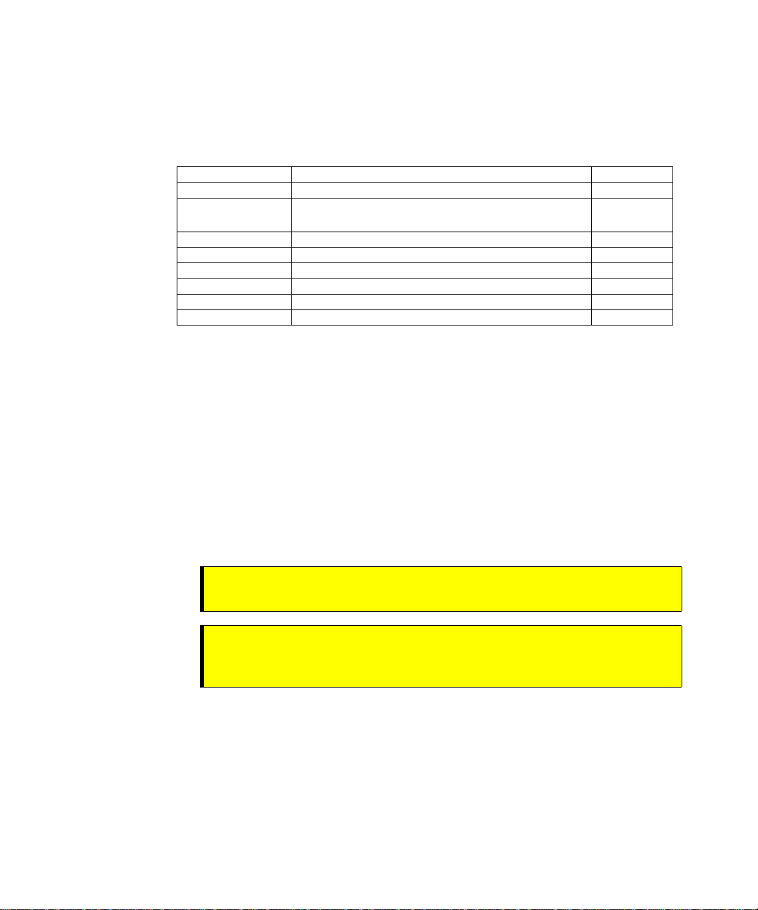
Spare Parts List
Part Reference Description Quantity
HI 6110 HI 6300 Series Instrument Display (Optional) 1
0551-0653-01-0 HI 6300 Series Alt. Panel and Wall Mount Kit
0578-0072-01 Paper Mounting Template 1
0524-0034-01-0 Mounting Gasket 1
2140-0092-0 J1, 3-pin Power Connector 1
2140-0139-09-0 J2, 9-pin Load Cell Connector 1
2140-0139-06-0 J3, 6-pin Serial Port Connector 1
2140-0139-03-0 J4, 3-pin 4-20mA Connector 1
Tool List
Step 5. Be sure to complete the warranty registration on the Hardy Process Solutions web
site.
1
(optional)
To install the HI 6300 series the following tools will be required.
•
Drill with 5mm drill bit
•
Jewelers screw driver (if cable assemble needs to be modified)
•
4mm nut driver with a maximum outside dimension of 8mm
•
10-50 mm Unibit (for optional display installation)
•
•
•
8
Chapter 3
•
•
•
Installing the HI 6300 Series Instrument
Before getting started, take the following precautions:
WARNING -
the module. DO NOT TOUCH THE CONNECTOR PINS.
WARNING AVERTISSEMENT –
endommager les composants semi-conducteurs dans le module. NE TOUCHEZ
PAS les broches du connecteur.
•
Wear an approved wrist-strap grounding device when handling the module.
•
Touch a grounded object or surface to rid yourself of any electrostatic discharged prior
to handling the module.
•
Handle the module from the bezel in front away from the connector. Do not touch the
connector pins.
•
Do not install the module right next to an AC or high voltage DC module.
•
Route all the low voltage cables away from high voltage cables.
Electrostatic discharge may damage semiconductor components in
Les décharges électrostatiques peuvent
Page 17
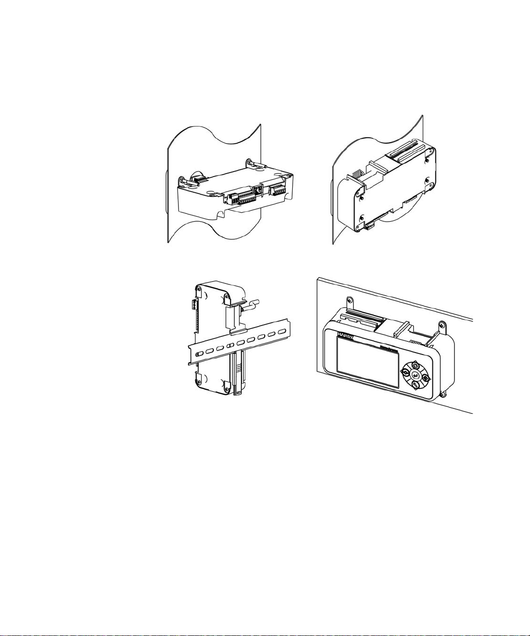
Installation options for the HI 6300 series instrument
The HI 6300 series instrument can be mounted in four different configurations. There are
two panel mount options, one DIN rail mount option, and a wall mount option.
Panel Mount Option 1 with mounting kit Panel Mount Option 2
DIN Rail Mount Wall Mount with mounting kit
Panel Mount Option 1 and Wall Mounts require additional hardware, which is
available in the Panel Mount Option 1 and Wa ll Mount kit sold separately (Part#
0551-0653-01-0).
The following sections provide details on how to mount the front panel display on a
panel door or cover and how to install and connect the front panel to the HI 6300 series
instrument for each of these four configurations.
Mounting the Front Panel Display
Step 1. Make sure that all Electrostatic Discharge (ESD) precautions are taken before and
during installation.
Installation
•
•
•
9
•
•
•
Page 18
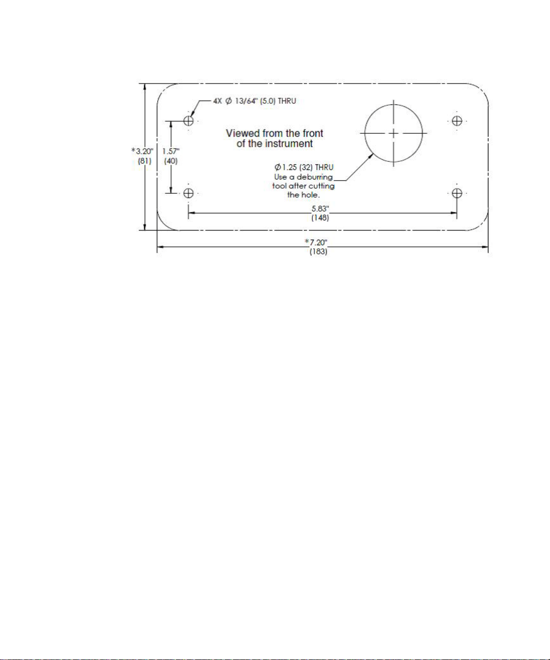
Step 2. A thin plastic template comes with the product. Make the hole pattern in the panel
door or cover using the dimensions provided on the diagrams below.
Panel Hole Dimensions (not displayed to scale)
A printable template is available on the Hardy website. Printers and copy machines can
distort or reduce the template measurements shown above. If you are not using the plastic
template included with the product, verify the dimensional accuracy of any paper template
before use.
CAUTION: We recommend installing the HI 6300 in a NEMA 4, 4X or IP 55 rated enclosure or better.
•
•
•
10
Chapter 3
•
•
•
ATTENTION
Nous vous recommandons d'installer le HI 6300 dans un boîtier NEMA 4, 4X ou IP 55
ou mieux.
Page 19
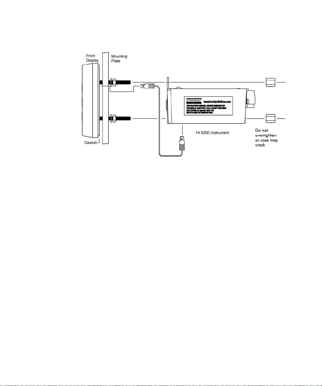
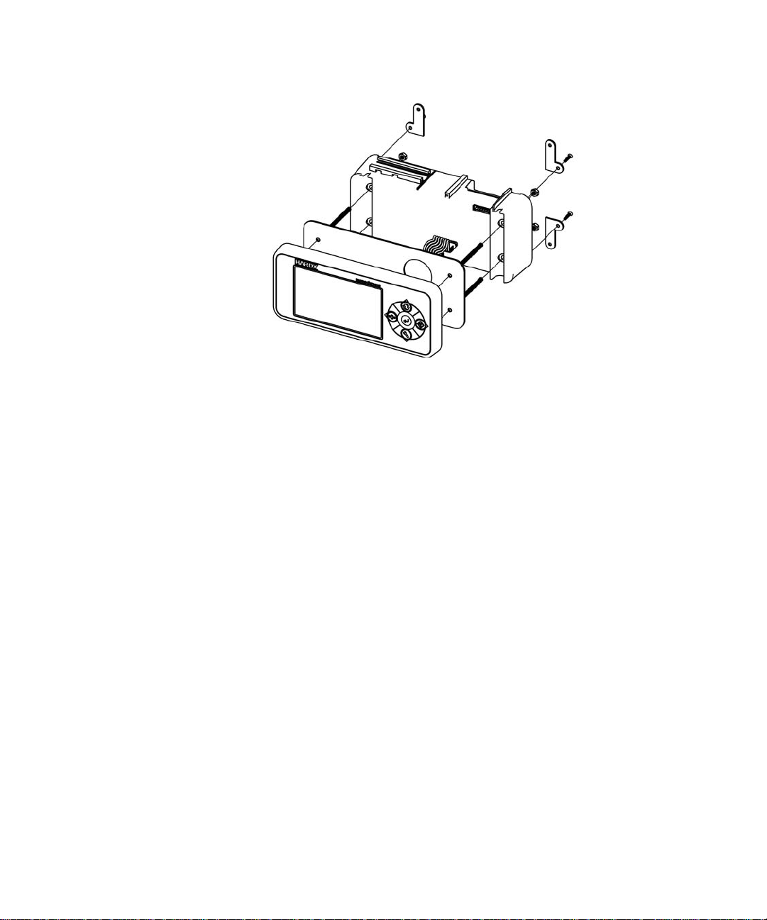
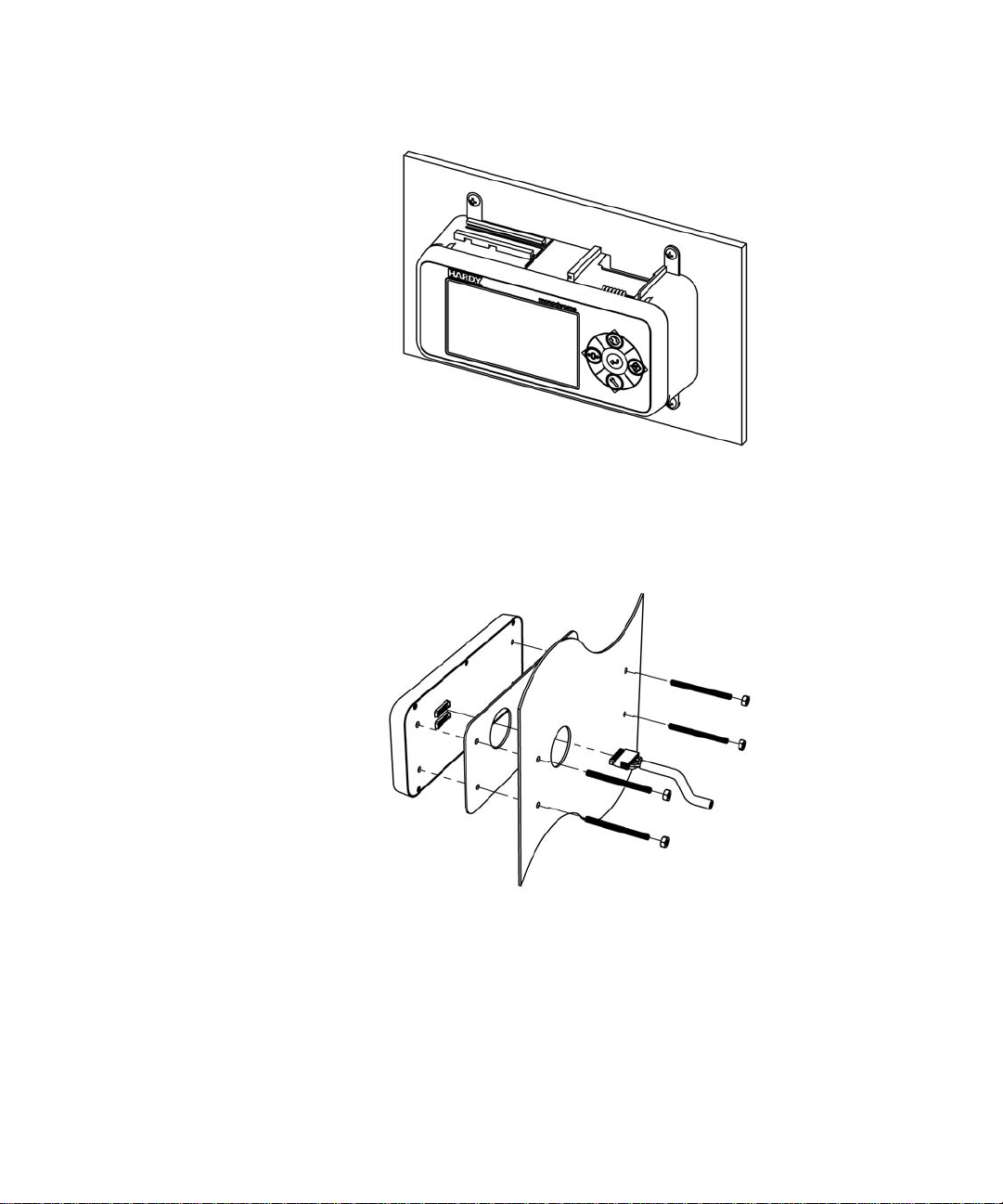
Panel Mount Option 1
FIG. 1 Exploded View of the Panel Mount Assembly – Option 1 with optional
mounting kit
Step 1. Screw the Panel Mounting Brackets to the top of the enclosure
Step 2. Connect and hand tighten the four screw rods into the front panel display
Step 3. Push the screw rods and cable assembly though the holes in the panel.
Step 4. Connect the front panel display cable assembly
Step 5. Tighten the four 4mm nuts enough to completely compress the gasket for IP65
Step 6. Position the enclosure with the connectors at the back
Step 7. Align the screw rods with the holes in the brackets and the enclosure
Step 8. Connect the cable assembly
Step 9. Slide the enclosure onto the screw rods until flush with the panel
Step 10. Install and tighten keeper nuts.
CAUTION: Do not over tighten the bracket screws or the mounting nuts as this may damage the
enclosure.
ATTENTION
Ne pas trop serrer les écrous de montage car cela pourrait endommager l'enceinte.
Installation
•
•
•
11
•
•
•
Page 20
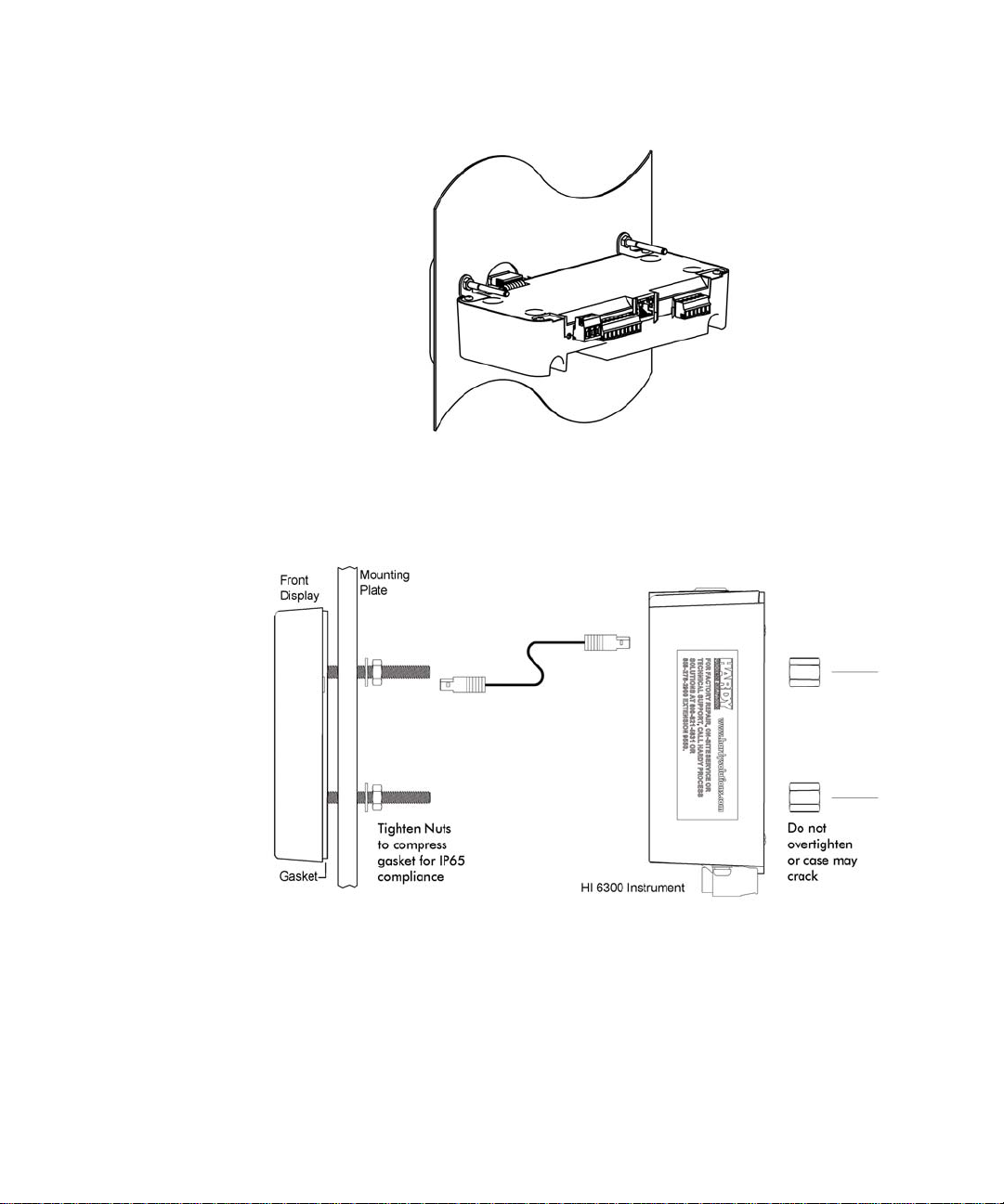
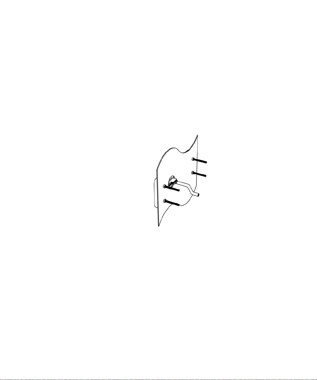
NOTE
Finished Panel Mount Assembly – Option 1
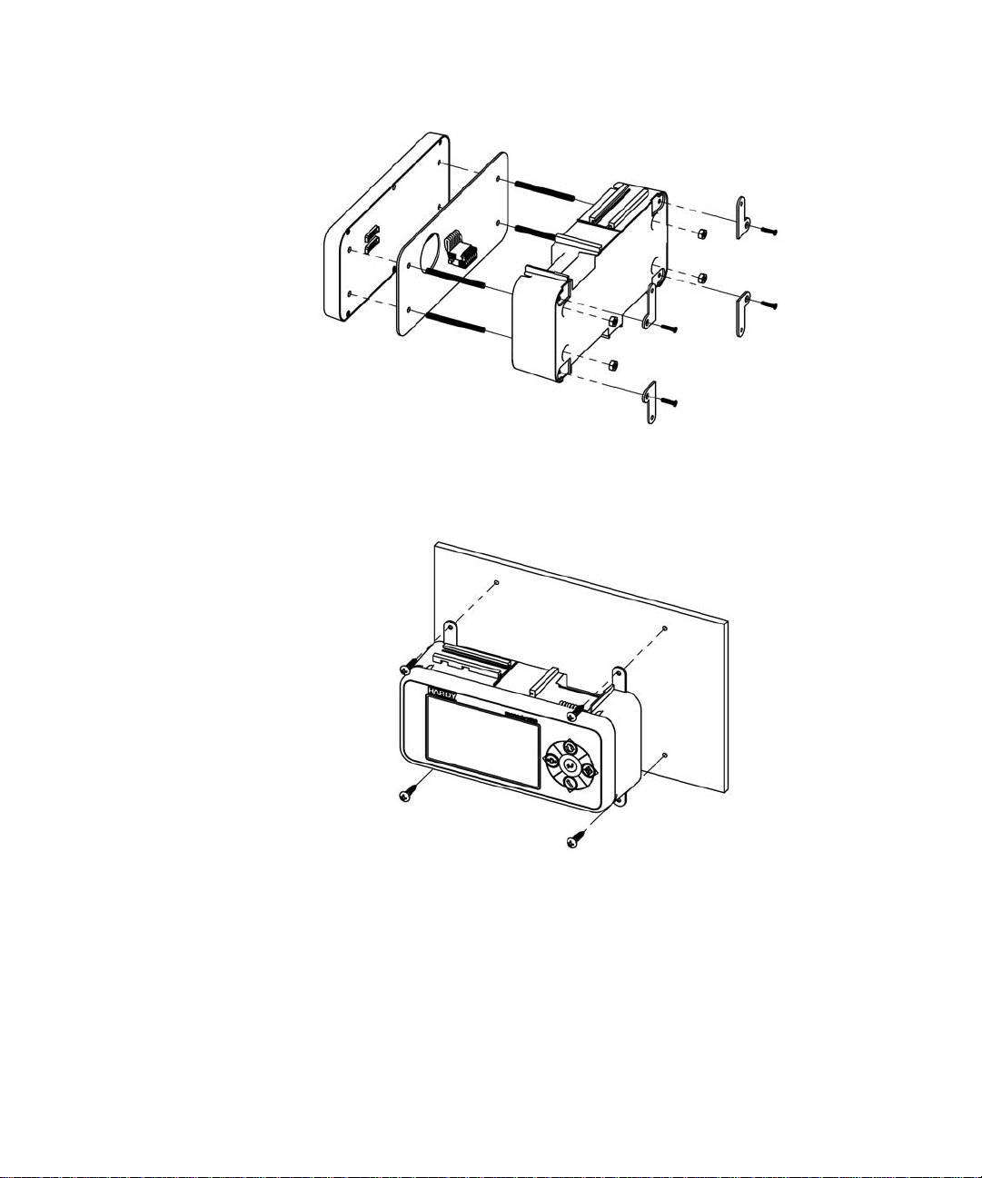
Panel Mount Option 2
Exploded View of the Panel Mount Assembly – Option 2
No brackets are needed for this installation.
•
•
•
12
Chapter 3
•
•
•
Step 1.
Connect and hand tighten the four screw rods into the front panel display
Step 2. Connect the front panel display cable assembly
Step 3. Push the screw rods and cable assembly though the holes in the panel.
Page 21
Step 4. Secure display to panel using four 4mm nuts and washers on the screw rods.
Step 5. Tighten the four 4mm nuts enough to completely compress the gasket for IP65
compliance.
Step 6. Position the enclosure with the connectors pointing downwards
Step 7. Align the screw rods with the holes in the enclosure
Step 8. Connect the cable assembly
Step 9. Slide the enclosure onto the screw rods until flush with the panel
Step 10.
Using the 4 mm x 12 mm keeper nuts supplied, secure the enclosure screw rods
CAUTION: Do not over tighten the bracket screws or the mounting nuts as this may damage the
enclosure.
ATTENTION
Ne pas trop serrer les écrous de montage car cela pourrait endommager l'enceinte.
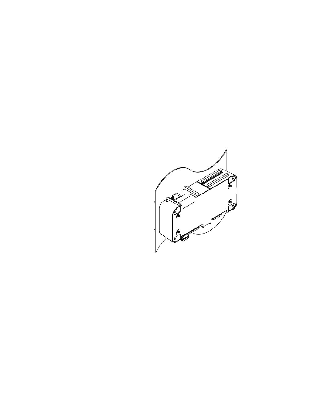
Finished Panel Mount Assembly – Option 2
Making Longer Display Interface Cables
If you need to install the front panel further away from the HI 6300 series than is possible
with the supplied cable then, you will need to make a display cable between the panel and
the instrument.
Wiring Specifications
•
Wire size: 20 AVG maximum / 26 AWG minimum
•
Maximum cable length: 100 ft. (30.48 meters)
•
Use three twisted pairs with a drain wires
•
Pair wires +12 and GND, D1 and D2, D3, and D4
Installation
•
•
•
13
•
•
•
Page 22
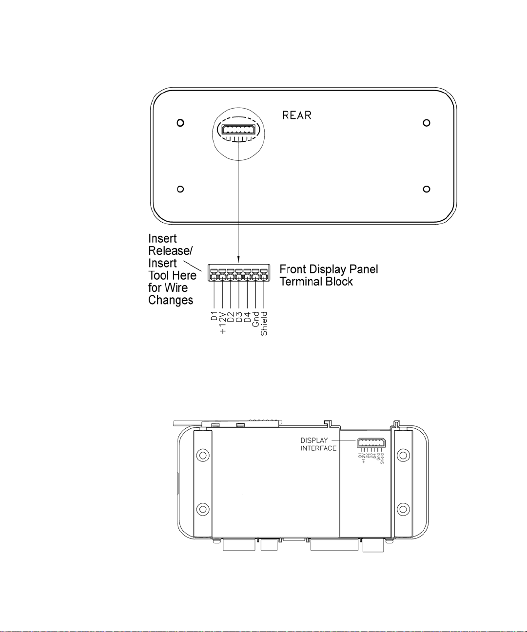
View from the rear of the front display panel
The terminal type is a spring cage type contact. There is a slot provided to use an
insert/release tool. The tool is a 2.0 mm x 0.4 mm wide flat blade screw driver. Inserting
the tool opens the cage contact and allows one or two bare wires to be inserted. Removing
the insertion tool with bare conductor inserted will lock the connection.
•
•
•
14
Chapter 3
•
•
•
View from the front of the instrument showing the display connector.
Page 23
NOTE
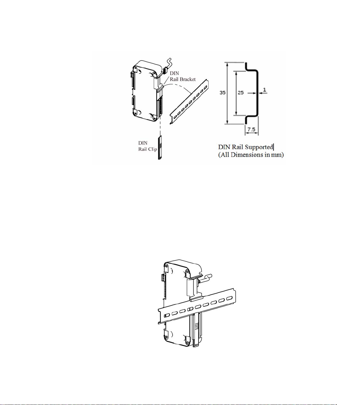
DIN Rail Mount
Exploded View of the DIN Rail Mount Assembly
The DIN Rail mount can be used with a remote display or operated as a Blind unit
Step 1. Pull down the DIN rail clip to expose the DIN Rail bracket. Do not fully remove the
clip from the housing.
Step 2. Hook DIN rail bracket onto the DIN rail using the groove at the top of the bracket
Step 3. Push the DIN rail clip up until it locks in place.
Step 4. While holding the HI 6300 series instrument, gently pull the bottom of the HI 6300
away from the DIN rail to verify that it is mounted correctly.
Completed DIN Rail Mount Assembly
Installation
•
•
•
15
•
•
•
Page 24
Wall Mount
Wall Mount Assembly exploded from the front with optional mounting kit
To wall mount the HI 6300 series instrument, the display and weight processor need to be
assembled; then the assembled instrument can be mounted onto the wall.
Step 1. Connect and hand tighten the four screw rods into the front panel display
Step 2. Connect the front panel display cable assembly
Step 3. Push the screw rods and cable assembly though the holes in the gasket.
Step 4. Position the enclosure with the connectors pointing downwards
•
•
•
16
Chapter 3
•
•
•
Step 5. Align the screw rods with the holes in the enclosure
Step 6. Connect the cable assembly
Step 7. Slide the enclosure onto the screw rods until flush with the gasket
Step 8. Using the washers and nuts supplied, tightened the nuts onto the screw rods
Page 25
Step 1. Attach the mounting brackets using the supplied brackets and screws
Exploded View of the Wall Mount Assembly – Rear View
Step 2. Place the assembled wall mounted unit against the wall
Step 3. Mark the centers of the wall mounting brackets
Step 4. Drill and insert the required wall plugs if attaching to brick, concrete, or plaster board.
If attaching to wood use a pilot drill to ensure alignment.
Step 5. Position the assembled wall unit over the holes and using the appropriate screw fasten
to the wall.
Installation
•
•
•
17
•
•
•
Page 26
Completed Wall Mount Assembly
Remote Display Mount
Exploded View of the Remote Display Mount Assembly
The display for the HI 6300 series instrument can be mounted in a remote location and
the supplied cable can be modified to support the desired length of cable (not supplied).
Step 1. Connect and hand tighten the four screw rods into the front panel display
•
•
•
18
Chapter 3
•
•
•
Page 27
Step 2. Disable the cable assembly provided, and replace the original cable with the desired
cable length (not provided--up to 100 ft (30.48 meters)). Build the cable assembly
using the instructions above for
13
.
Making Longer Display Interface Cables
on page
Step 3. Connect the front panel to the newly assembled display cable
Step 4. Push the screw rods and cable assembly though the holes in the gasket.
Step 5. Slide the screw rods through the panel until flush with the surface
Step 6. Using the washers and nuts supplied, tightened the nuts onto the screw rods. Tighten
the nuts enough to completely compress the gasket for IP65 compliance
Step 7. Connect the cable assembly to the HI 6300 series instrument
Finished Remote Display Mount Assembly
Blind Unit (No display)
The front display is not necessary for the HI 6300 series instrument to operate as a scale
controller. Blind units can be fully configured using the Web browser communication.
Installation
•
•
•
19
•
•
•
Page 28
DC Power Input
WARNING - Do not operate with incorrect line voltage. To do so will result in
property damage and/or personal injury. Make sure that the power source does
not exceed 24 VDC.
AVERTISSEMENT –
Assurez-vous que la source d’alimentation ne dépasse pas
240 V. L’utilisation d’un mauvaise voltage peut résulter en dégâts matériels
et/ou des risques de blessures.
WARNING - Be careful not to reverse the ground and hot wires, which can
result in damage to the equipment.
AVERTISSEMENT –
Attention à ne pas inverser le sol et fils chauds, ce qui peut
entraîner des dommages à l'équipement.
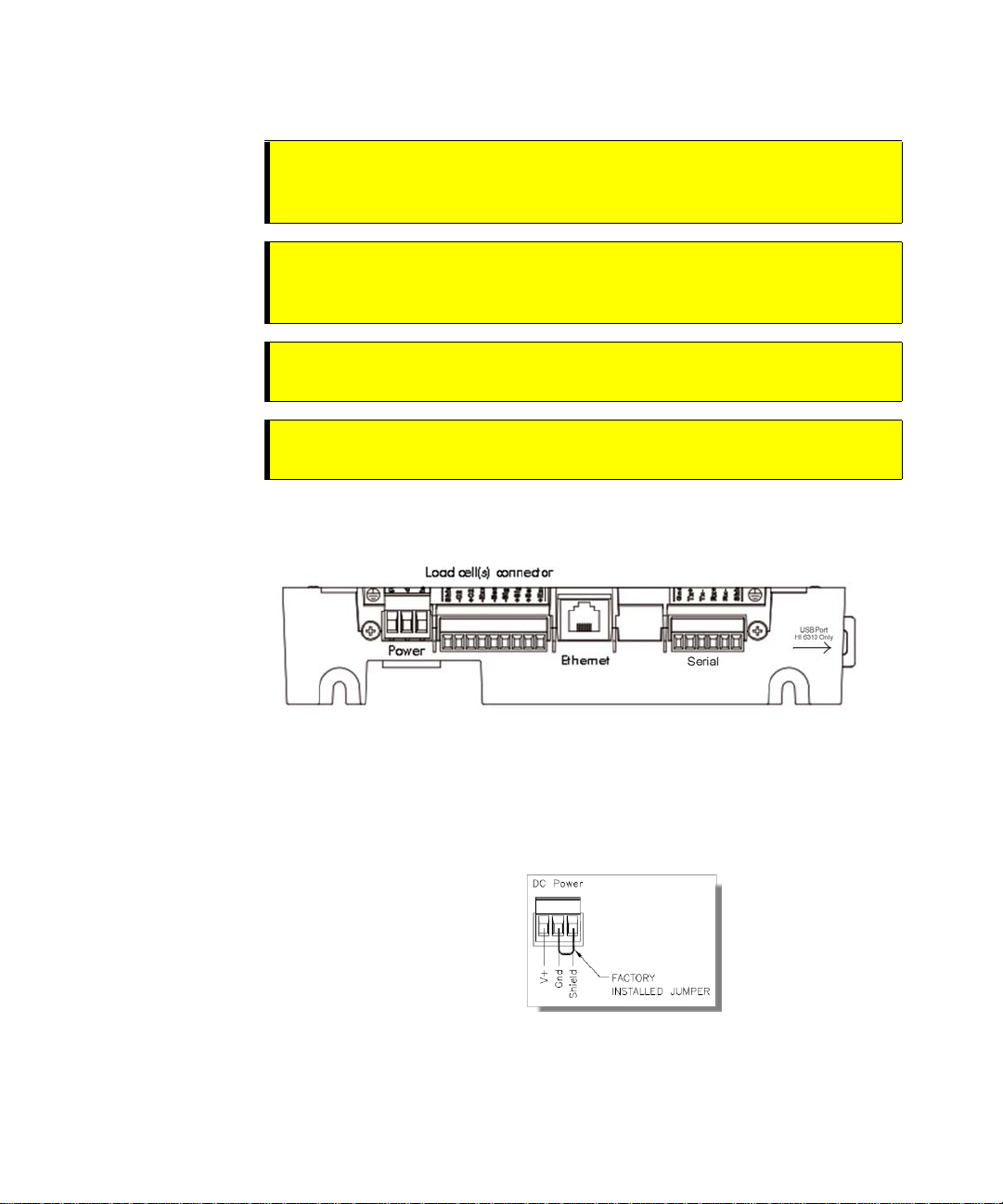
The illustration below shows the connections on the HI 6300 unit.
You must use a power-limited DC power supply (Class 2) on the DC input wiring. DC
power should be supplied by a clean primary line, directly from the DC power source.
Step 1. Make sure the VDC power is shut off before installing the wires to the connector.
Step 2. Connect the 24 VDC voltage wire, ground wire and shield wire to the connector that
plugs into the DC voltage header at the rear panel.
•
•
•
20
Chapter 3
•
•
•
Step 3. Plug the connector into the header at the rear panel.
Step 4. Apply VDC power to the unit.
Page 29

Disassembly and Reassembly Notes and Cautions
•
Installation of this equipment must comply with International, National and Local
Electrical and Mechanical codes.
•
Make sure that any disassembly is done in a clean, well ventilated, properly controlled
static-free environment.
•
Always make sure that the assemblies and sub-assemblies are well supported and
insulated when working on the instrument.
•
Place small fasteners, connectors and electrical parts in closed containers so as not to
lose parts during reassembly.
•
Read the disassembly instructions before disassembly. If you find the instructions for
disassembly unclear, contact the Hardy Process Solutions Technical Support
Department for additional information and assistance.
•
Do not disconnect any electrical plug, connector or terminal unless an identification tag
is present or one is attached. Always note where the connector or plug was attached to
the electrical component or wiring harness.
•
Install complete hardware groups (screws, washers, lock washers, spacers, etc.) back to
the original point of removal.
•
Replace broken or damaged hardware immediately!
•
Verify that no loose parts are sitting on printed circuit boards or electrical connectors or
wires when disassembling or reassembling.
•
Always protect printed circuit boards from electrostatic discharge (ESD). Always use
approved ESD wrist straps and anti-static pads.
Installation
•
•
•
21
•
•
•
Page 30
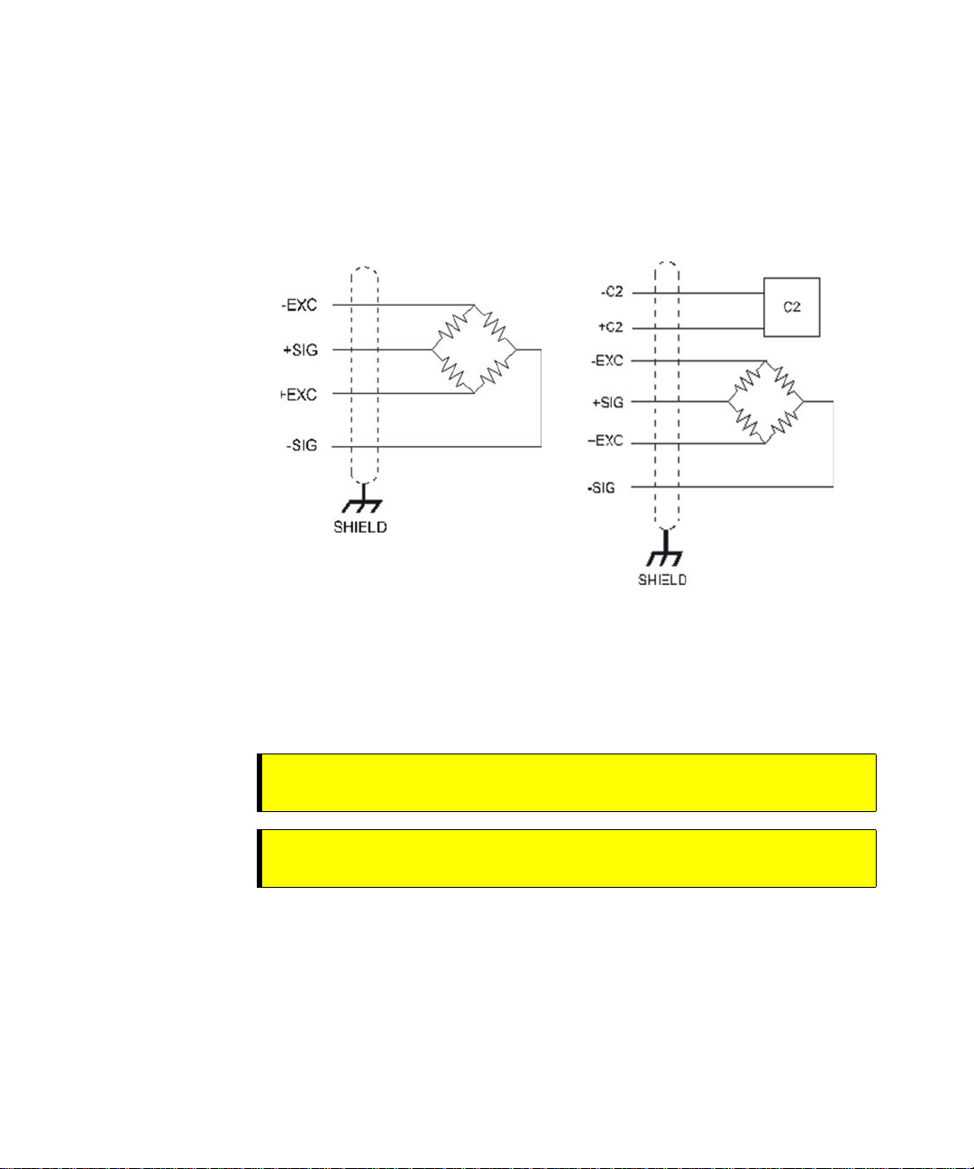
Load Cell Wiring Diagrams
The diagrams below show how Hardy Load Sensor with C2 wiring differs from
standard Load Cell wiring. C2 wiring is required when using a Integrated Technician
summing junction box. The C2 wires are used for communicating IT and C2
commands.
Industry standard load cells wiring Hardy load sensor C2 wiring
•
•
•
22
Chapter 3
•
•
•
The simple wiring diagram above shows how to connect a single load cell to the HI
6300 series instrument. Note: when connecting the HI 6300 series instrument to a
junction box, the sense lines would be connected between the +Sen and –Sen
Connections for the junction box and the instrument.
WARNING - Instrument power should be routed away from all other signal
cables to avoid electrical interference.
AVERTISSEMENT –
Tension de l'appareil doivent être acheminés à l'écart de
tous les autres câbles de signaux pour éviter toute interférence électrique.
Page 31

Connecting to the Hardy HI 215IT or HI 6010/6020IT Summing Box
HI 215 Junction Box Wiring Diagram
Installation
•
•
•
23
•
•
•
Page 32

NOTE
HI 6010 Summing Box Diagram
When connecting a Hardy Summing Box to the HI 6300, you must remove the two
factory installed jumpers on pins 1 & 2 and on pins 5 & 6 on the module and install
C2 and sense wires. C2 wires carry the commands for Integrated Technician and the
C2 calibration information.
•
•
•
24
Chapter 3
•
•
•
Page 33

Chapter 4
• • • • • •
Network Configuration
Chapter Four contains step-by-step instructions for configuring Hardy HI 6300 series
instruments and related communication networks. We recommend reading these
procedures because having a correct configuration is necessary to ensure trouble-free
operation.
This chapter explains how to either configure the HI 6300 series instrument from its
own front panel or with a PC-based Web interface connected to the HI 6300 series
instrument over a standard Ethernet network. The features of the HI 6300 series
instrument operate the same way in either case. You must use the Web interface to
configure units that do not have a display.
Before operating the HI 6300Weight Processor, make sure that:
•
Power and load point cables are properly installed and in working order.
•
Communication cables are properly installed and in working order.
Ethernet TCP/IP
NOTE
Do not confuse the on-board Ethernet TCP/IP communication with EtherNet/IP®.
Ethernet/IP is an industrial protocol that does not transmit Web traffic.
An embedded Web server in the HI 6300 series instrument allows you to easily configure
every parameter of the instrument via a standard Web browser. A standard Ethernet
network is required to provide the connectivity between the HI 6300 series instrument and
your desktop / laptop computer.
The HI 6300 series instrument is designed with a standard 10/100 BASE-T Ethernet
connection for linking to any Windows PC. Once connected, you can monitor, download
Hardy software from the Internet, or configure the HI 6300 series instrument from that PC.
A Help function can assist you in setup or trouble-shooting. The browser also links to the
Hardy Web Site where the user can find additional services and support.
There are two primary ways to connect the HI 6300 series instrument to your computer:
LAN Connection: Connect the HI 6300 series instrument to an existing Ethernet-
Network Configuration
based Local Area Network (LAN) that has connectivity to your
desktop or laptop computer. See the LAN Connection section
below.
Network Configuration
•
•
•
25
•
•
•
Page 34

Direct Connection:
LAN Connection
To connect the HI 6300 series instrument to a LAN, you simply connect a standard Ethernet
cable between the instrument and the common network hub. You will then need to
determine which scheme is used on the network to assign IP addresses. Every node on the
network must have a unique IP address or conflicts will result.
Contact your Network Administrator for the IP address to use for the instrument.
The IP address can be set manually (Fixed IP), or it can be set automatically by a network
service called DHCP.
A direct point-to-point connection between the HI-6300 and your
desktop or laptop computer using any standard Ethernet cable. See
the
Direct Connection
section below.
NOTE
NOTE
If the DHCP service fails, the instrument will default to the Fixed IP address after a power cycle. If the DHCP service is repaired, the instrument will revert back to using the DHCP IP address.
If you are required to use Fixed IP addresses, refer to the section
Using the Front Panel
Fixed IP Configuration
below. For automatic IP assignment (DHCP), use the following
steps:
DHCP Configuration Using the Front Panel
DHCP works only if a DHCP server is installed on your network.
Step 1. From the Configuration menu, Use the UP or DOWN button to select the
communication menu, then select the Ethernet TCP/IP menu item.
Step 2. Select the DHCP menu item and use the ENTER key to enable/disable this
feature.
Step 3. Select the DHCP IP address menu item and verify that a correct IP address has
been assigned to the instrument by the network server. If an incorrect IP address
has been assigned contact your system administrator; or use a Fixed IP address.
Step 4. This is the IP address to use in your web browser to access the Web Interface.
From here you can jump to the section
You cannot change the values of the DHCP IP address. The LEFT button returns the
operator to the Ethernet TCP/IP Menu.
•
•
•
26
Chapter 4
•
•
•
Page 35

Fixed IP Configuration Using the Front Panel
The HI 6300 series instrument can be configured to use any Fixed IP address. The
Fixed IP addresses must be carefully selected to avoid accidentally configuring two
devices to the same address with unpredictable results. Since ‘guessing’ a value could
lead to personal or property damage and/or interrupted network services, your network
administrator should provide this address.
Read-only screens can display a limited number of characters per line. To see the complete
IP address in DHCP, you need to do the following:
Step 1. Press the CONFIG button to enter the Configuration menu; and use the UP or
DOWN buttons to select the Communication menu, then use the UP or DOWN
buttons to select the Ethernet TCP/IP menu item and press the RIGHT or ENTER
button to access the Ethernet TCP/IP menu.
Step 2. Select the Fixed IP menu item.
Step 3. Starting at the right-most digit, enter the IP number using the standard format. Use
the
UP or DOWN buttons to select each number, and press the LEFT or
RIGHT button to move between numbers.
Step 4.
Press the ENTER button to save the entry.
Step 5. Use the LEFT button to exit the menu structure.
Step 6. The IP address is now saved and the instrument’s embedded Web browser is now
availa
ble at the entered IP address. From here you can jump to the Network
Options Configuration section.
Step 7. Cycle power to establish the fixed IP address as the current operating address.
This method of interconnect between an HI 6300 series instrument and a standard Windows
PC allows you to configure the instrument using the embedded web browser, even if an
Ethernet network is not part of the normal installation. A desktop or laptop may be used on
location as necessary.
Step 1.
Both sides of the link require configuration of their IP addresses to establish
a working connection. The following steps will walk you through the process
of connecting the hardware and configuring the HI 6300 series instrument and
PC with compatible IP addresses.
From the Summary display, press Enter to
activate the Configuration menu. Use the down arrow to select Communications
and press Enter.
Step 2. Use the down arrow again to select Ethernet, and select IP to display the IP screen.
Network Configuration
•
•
•
27
•
•
•
Page 36

Step 3. Starting at the right-most digit, enter
the IP number using the standard
format. Use the up/down arrows to
select each character, and press the
left arrow to move to the next digit.
Step 4. Press Enter to save the entry.
Step 5. Press the Exit key four times to exit the IP, Ethernet,
configuration
menus.
communications and
The IP address is now saved and the instrument’s embedded Web browser is now available
at the entered IP address. From here you can jump to the
Network Options Configuration
section.
Both sides of the link require configuration of their IP addresses to establish a working
connection. The following steps will walk you through the process of connecting the
hardware and configuring the HI-6300 and PC with compatible IP addresses.
Direct Connect Hardware
Any standard Ethernet cable with RJ-45 connectors at each end can be used to connect
the HI 6300 series instrument to your PC. A ‘crossover’ cable is not required. Simply
plug the cable into each instrument.
Windows PC Configuration
Windows 2000
Step 1. After starting your computer, click the Start button.
Step 2. Click on Settings > Control Panel to display the Windows Control Panel.
Step 3. Click the Network icon to display the Network dialog.
Step 4. Click on TCP/IP; then click the Properties button to open the TCP/IP Properties
dialog. Click the IP Address tab.
Step 5. If the ‘Use the Following IP Address’ box is already checked, write down the
displayed IP Address and jump to the
Direct Connect Configuration – HI 6300
section below.
Step 6. Click the ‘Specify an IP Address’ check box; then enter the following into the
TCP/IP Properties dialog.
IP Address =
192.168.0.100
Subnet Mask = 255.255.255.000
Step 7. Select OK on the TCP/IP Properties dialog. The computer is now fully
configured.
Step 8. To return the PC to the original network settings, return to the ‘Internet Properties
(TCP/IP) dialog, select ‘Obtain an IP address automatically,’ and click OK.
•
•
•
28
Chapter 4
•
•
•
Page 37

Windows XP
Step 1. After starting your computer, click Start.and then Control Panel.
Step 2. Click on Settings > Network Connections.
Step 3. Right click on ‘Local Area Connection’ and select Properties.
Step 4. Click on Internet Protocol (TCP/IP) and click on the Properties button to open the
Internet Properties (TCP/IP) Properties dialog.
Step 5. If the ‘Use the Following IP Address’ box is already checked, write down the
displayed IP Address and jump to the
Direct Connect Configuration – HI 6300
section below.
Step 6. Click the ‘Use the Following IP Address’ check box; then enter the following into
the TCP/IP Properties dialog.
IP Address = 192.168.0.100
Subnet Mask = 255.255.255.000
Step 7. Select OK on the TCP/IP Properties dialog box. The computer is now fully
configured.
Step 8. To return the computer to the original network settings, return to the ‘Internet
Properties (TCP/IP) dialog, select ‘Obtain an IP address automatically,’ and click
OK.
Windows 7
Step 1. After starting your computer, click the Start button.
Step 2. Click on Control Panel to display the Windows Control Panel.
Step 3. Click on Network; then click Internet
Step 4. Click on Network Sharing Center.
Step 5. Click on Change Adapter Settings in the left-hand column.
Step 6. Right click on Local Area Connection and select Properties.
Step 7. Click on Internet Protocol Version 4 (TCP/IPV4)
Step 8. Click the Properties button to open the Internet Properties (TCP/IP) Properties
dialog.
Step 9. If the ‘Use the Following IP Address’ box is already checked, then write down the
displayed IP Address and jump to the
Direct Connect Configuration – HI 6300
section below.
Step 10. Click in the ‘Use the Following IP Address’ checkbox; then enter the following
into the TCP/IP Properties dialog.
IP Address = 192.168.0.100
Subnet Mask = 255.255.255.000
Network Configuration
•
•
•
29
•
•
•
Page 38

Step 11. Select OK in the TCP/IP Properties dialog box. The computer is now fully
configured.
Step 12. To return the computer to the original network settings, return to the Internet
Properties (TCP/IP) dialog , select ‘Obtain an IP address automatically,’ and click
OK.
Direct Connect Configuration - HI 6300 Series Instrument
The HI 6300 must now be assigned a unique IP address that will connect to the Windows
PC. There are two simple rules for the IP Address:
•
It must have the same network identifier
as the computer
•
It must have a different node identifier
than the computer.
If your Windows PC already had an IP address assigned, simply increment by one the Node
Identifier field of the IP Address you wrote down in the Windows PC configuration steps
above. If your Windows PC was originally set to automatically obtain an IP address
(DHCP), use 192.168.100.50 for the HI 6300 IP address.
Ethernet-UDP
HardyPort
UDP or TCP/IP. You send commands to the instrument to read or set parameters. The
commands are text strings of the form
is the Ethernet port number that one can use to connect to this instrument via
PARAMETERNUMBER
or
•
•
•
30
Chapter 4
•
•
•
PARAMETERNUMBER=PARAMETERVALUE
For example, send the command 00000090 to read the gross weight value. The response
will be something like:
Gross = 10.3
To set a parameter, send a command like 0000000D = 0.5 - this command sets the Motion
Tolerance parameter to 0.5
See the Operation/Diagnostics/Parameters web page for a list of parameter numbers.
The HI 6300 series instrument has only 1 TCP/IP socket available for this command
interface, so only 1 master can connect, say using HYPERTERMINAL Telnet. There
is no such limit with UDP – any number of masters can send UDP commands.
Page 39

Modbus-RTU (over RS-485
Step 1. Setup a slave address assigned to the HI 6300 series instrument from the
communications menu and the Modbus-RTU submenu.. Use a unique address
between 1 and 247
Step 2. Set the Baud Rate to the same as the master device, typically 9600 or 19,200
Step 3. Set the Parity Bit parameter to match that of the Modbus-RTU master (EVEN,
ODD, or OFF)
Wiring Pinout
)
The RS 485 serial port pinout is:
Pin 1 Pin 2 Pin 3 Pin 4 Pin 5 Pin 6
Ground TX+ TX- RX+ RX- Shield
Modbus Setup
•
Slave Address
•
Set
Baud Rate
•
Set
Parity
may be set to any number in the range of 1-247.
parameter to match the settings of the Modbus master
to match the settings of the Modbus master
Network Configuration
•
•
•
31
•
•
•
Page 40

Modbus Functions
The Modbus functions allowed in the HI 6300 are:
Function 3: Modbus Read Holding Registers
Function 4: Modbus Read Input Registers
Function 6: Modbus Write Single Register
Function 16 (0x10): Modbus Write Multiple Registers.
Modbus Registers
This instrument has 64 16-bit MODBUS input registers and 64 16-bit output registers. The
data in these registers is in "big endian" format, meaning that the most significant byte
comes first.
•
The first 6 registers (0 – 5) are used for the “command interface” in the unit.
•
Registers 6 & 7 will contain the Net weight in 32 bit floating point format.
•
Registers 8 & 9 will contain the Gross weight in 32 bit floating point format.
•
Registers 10 and 11 will contain the statusword
•
Registers 12 and 13 (HI 6310 only) are for the count function.
Network Command Interface
The "network command interface" uses 6 registers (0 – 5) in and 6 registers out.
•
Register 0: command (shown below)
•
Register 1: status
•
Registers 2, 3: Parameter number. See the diagnostics/parameters web page for a list of
parameter numbers.
•
Registers 4, 5: parameter value
The Modbus master sends a 'command' by writing a value to register 0.
return value is an error.
Any non-zero
•
•
•
32
Chapter 4
•
•
•
Here is a list of Hardy command numbers:
•
0: READ PARAM CMD
(register #0), and write the parameter number in the parameter ID number in registers 2
and 3, most significant word first. The parameter value may then be read from registers
4 and 5, again most significant word first. This value may be in integer or floating point
format, depending on the parameter. The status register in the reply will contain the
lower 16 bits of the system status word.
•
Status word bit 0: A/D error.
•
Status word bit 6 (0x40): Motion status.
•
Status word bit 15 (0x8000): Not Found - the requested parameter number does
not exist
•
1: ZERO CMD
status register will read 0 if this command succeeds.
•
•
. Write a #1 to the command register to ZERO the gross weight. The
Status Error code 1 (motion)
Status Error code 2 (A/D error)
. To read a parameter, write a #0 to the command register
Page 41

•
Status Error code 3 (out of tolerance)
•
2: T ARE CMD
register will read 0 if this command succeeds:
•
•
•
4: WRITE NONVOL CMD
non-volatile memory.
•
•
0x64 (100 decimal): CAL LOW CMD
perform the low step of a traditional calibration. The status register will read 0 if this
command succeeds:
•
•
•
•
0x65 (101decimal): CAL HIGH CMD
perform the high step of a traditional calibration.
•
•
•
•
. Write a #2 to the command register to ZERO the net weight. The status
Status Error code 1 (motion)
Status Error code 2 (A/D error)
. Write a #4 to the command register to save parameters in
No Error Codes
Calibration_Fail 1
Calibration_Fail_Motion 3
Calibration_Fail_Adc_Error 4
Calibration_Fail 1
Calibration_Fail_Motion 3
Calibration_Fail_Adc_Error 4
HardcalFailCounts 8: not enough counts between hard cal hi and hard cal lo
. Write a 0x64 hex to the command register to
. Write a 0x65 hex to the command register to
•
0x66 (102 decimal): C2 CAL CMD
perform a C2 calibration.
•
Calibration_Fail 1
•
Calibration_Fail_Motion 3
•
Calibration_Fail_Adc_Error 4
•
Calibration_Fail_Noc2 5
•
Calibration_Fail_C2capeq 6
•
Calibration_Fail_C2clones 7
•
0x1000 (4096 decimal): WRITE INTEGER CMD
parameter. Write 0x1000 in the command register 0, the parameter ID number in
registers 2, 3 and the desired value in registers 4, 5.
•
No Error Codes
•
0x1001 (4097 decimal): WRITE FLOAT CMD
parameter. Write 0x1001 in the command register 0, the parameter ID number in
registers 2, 3 and the desired float value in registers 4, 5.
•
Failure 1
. Write a 0x66 hex to the command register to
. Set the value of an integer
. Set the value of a floating point
Network Configuration
•
•
•
33
•
•
•
Page 42

•
TooHigh -1 : value is above legal limit
•
TooLow -2 : value is below legal limit
•
ErrorNotFound 0x8000 : parameter id not found
All communications will be controlled by the Modbus functions. The Modbus
protocol will determine the function, address, size, and offset register for the
message. The command interface data will be within the data portion of the
message and will define the command to our unit.
Example 1: If you wish to read the span weight value you would:
1. Enter the Span parameter ID into registers 2 & 3. The Span ID is 0x0000 0201.
a. Place 0x0000 into data register #2.
b. Place 0x0201 into data register #3.
2. Enter the command #0 into data register #0.
3. Run the Modbus Function code #16 (write multiple registers).
4. Run the Modbus Function code #4 (read multiple registers).
5. Read the value for the span parameter in data registers #4 & 5. This value will be
in floating point format.
•
•
•
34
Chapter 4
•
•
•
Example 2: If you wish to write a new span value of 100.55:
1. Enter the Span parameter ID into data registers 2 & 3. The Span ID is
0x0000 0201.
a. Place 0x0000 into data register #2.
b. Place 0x0201 into data register #3.
2. Enter the new value into data registers 4 & 5. The float value 100.55 in hex is
0x42C9 1999.
a. Place 0x42C9 into data register #4.
b. Place 0x1999 into data register #5.
3. Enter the write float command into data register #0. The write float command is
0x1001.
a. Place 0x1001 into data register #0.
Page 43

4. Run the Modbus Function code #16 (write multiple registers).
5. Run the Modbus Function code #4 (read multiple registers). This will allow the
user to read the status of the command in data register #1.
If you wish to then read back the value you have written:
6. Enter the command #0 into data register #0.
7. Run the Modbus Function code #16 (write multiple registers), or Function code
#6 (write single register) insuring the correct data location is being set.
8. Run the Modbus Function code #4 (read multiple registers).
Read the value for the span parameter in data registers #4 & 5. This value will be in
floating point format.
Communications Parameters for the HI 6310 Only
Printer (over RS-232)
Available on the HI 6310 only.
The HI 6310 can transmit Gross, Net, Count, Tare values to a serial printer over RS-232.
The printer Baud rate is user selectable at 600, 1200, 2400, 4800, 9600, or 19200 (default
is 9600).
A sample wiring connection from the HI 6310 to the printer port is shown above. The
printer parameters can be configured through the web interface or the display panel.
Step 1. Set the baud rate for the RS232 printer, default is 9600.
Step 2. Set the parity bit, default is EVEN
Step 3. Select what values to transmit over the serial interface to the printer using the
printer mode, default is disabled.
Network Configuration
•
•
•
35
•
•
•
Page 44

a. Gross Weight
b. Net Weight
c. Tare Weight
d. Unit Count
e. All – Gross, Net, Tare, and Count (if Count enabled) values
f. OFF, Printer disabled.
USB Memory Stick
Available on the HI 6310 only.
The HI 6310 provides an interface to an external USB memory stick that allows HI 6310
parameters to be saved, restored. or copied to another instrument.
The USB memory stick commands can be activated through the web interface or the
display panel.
To access the USB Menu, from the front keypad, select Configuration > Enter,
Communications > Enter, USB >Enter, UP or DOWN arrow to Save or Restore > Enter.
On the
Web page
: Configuration; communications; USB; save/restore.
•
•
•
36
Chapter 4
•
•
•
Step 1. Insert the USB stick into the HI6310
Step 2. Using the web interface or display panel, save or restore system parameters.
Analog 4-20mA
Available on the HI6310 only
The analog 4-20mA output is directly proportional to the programmed gross, net, or count
range; by setting the low value equal to 4mA and the high value equal to 20mA. These
values can be set from either the front panel or the web interface.
Page 45

The 4-20mA parameters can be configured through the web interface or the display panel.
From the front display: select the configuration menu then UP or DOWN to
communications, enter; UP or DOWN to 4-20mA, enter; UP or DOWN to setting you
want for Source; enter the value for 4mA; enter the value for 20mA or mA output (read
only). Press enter to select and UP or DOWN arrows to enter value.From the Website,
select the Communications Menu and then
Step 1. Select the source for the 4 to 20mA output, default is gross
a. Gross.
b. Net
c. Count
d. Manual
Step 2. Set the 4mA value
Step 3. Set he 20mA value
Step 4. Save Parameters
NOTE
Setting the weigh source to manual allows the mA output setting to be set to a fixed
output. This is used to test the circuit level to the host.
Network Configuration
•
•
•
37
•
•
•
Page 46

•
•
•
38
Chapter 4
•
•
•
Page 47

Chapter 5
• • • • • •
Instrument Configuration
Using the Home Page to set Parameters
Enter your HI 6300 series home page by typing the IP Address you used to set up the
instrument (see Chapter 4 for information on setting the IP Address) accessing the
instrument via a direct connection on a PC.
From the Home Page, click Configuration to open the Configuration page. Select
Instrument Setup to open the Instrument Setup page.
The HI 6300 series instrument Configuration process sets up the instrument to operate
as a scale. This includes configuring, units of measure, WAVERSAVER®, motion
tolerance and other instrument parameters required for your process.
Instrument Configuration
•
•
•
39
•
•
•
Page 48

Using the Front Panel Display Menus to Set Parameters
Front Panel Display
The Front Panel Display is a 480 x 272 LCD graphical display. The Summary screen
displays the current weight in the selected mode (Gross, Net or Count (HI 6310 only))
and the selected engineering units (oz, lb, t (ton), g, kg, mt (Metric Ton)).
The Five Button Command Cluster
•
•
•
40
Chapter 5
•
•
•
TARE Command Button
When the TARE button is pressed the NET weight value is set to zero.
Page 49

ZERO Command Button
When the ZERO button is pressed the GROSS weight value is set to zero.
MODE Command Button
The MODE button toggles the weight displayed between GROSS and NET.
•
HI6310 only. Count is included if this mode is enabled
CONFIG (Configuration) Command Button
The CONFIG button minimizes the displayed weight value and provides a submenu
structure on the screen which is navigated by the button cluster.
Press
ENTER
button to display the Menus and Sub-Menus or to enter the configured
values or selected items form a pick list into non-volatile memory.
•
HI6310 only. The ENTER button acts as a PRINT key, when the print mode is enabled.
The second level menu functions are selected when the CONFIG button is pressed. While
the unit is in the second level menu the function for each button is changed to UP, DOWN,
LEFT, or RIGHT to allow the user to navigate, select, and/or enter values for different
parameters to configure the instrument.
To move UP or DOWN a list of submenu items the UP or DOWN buttons are used. To
select the submenu item either the ENTER or RIGHT button can be used. When the
ENTER or RIGHT button is pressed the menu structure transitions to a lower level in
the menu hierarchy. This lower level may have an additional submenu list to select
from or it may require the user to enter a value.
Using the Mode, Zero, and Tare buttons
The HI6300 series instrument Weight Controller display shows the weight in Gross or
Net mode. Use the MODE button to change from displaying Gross weights to
displaying Net weights.
To Tare the Scale, press the
“Tare OK.” If the Tare is unsuccessful, you will get a message “Tare Failed.” Check the
Motion Tolerance parameter. Chapter 4 provides configuration instructions for the Motion
Tolerance Parameter.
To Zero the Scale, press the ZERO button. If the Zero is successful you will get a message:
“Zero OK.” If the Zero is unsuccessful, you will get a “Zero Failed” message. Check the
Zero Tolerance parameter. Instructions for setting the Zero Tolerance parameter value is
provided in Chapter 4.
TARE
button. If the Tare is successful, you will get a message:
Instrument Configuration
•
•
•
41
•
•
•
Page 50

The CONFIG Menu Structure
To configure and setup the HI 6300 series instrument press the CONFIG button. To enable
the user to continue to monitor the process the display the weight, mode, and zero symbol
are reduced and placed in the top right hand corner.
A submenu list is provided on the left hand side, with the item that would be selected
by highlighted and identified by the ♦ symbol.
•
•
•
42
Chapter 5
•
•
•
The numeric or alphanumeric value for the selected item is display in the area shown as
--- Value -----
in the above illustration, along with help text for the item selected.
--
If more than five item are in the submenu list, use the UP/DOWN button to scroll through
the submenu list. To select the item from the submenu list press the RIGHT or ENTER key.
Entering Numeric and Alphanumeric Values
At the lowest level of the menu hierarchy the user may need to enter a numeric or which
could represent a tolerance or an Ethernet IP address or an alphanumeric value for entering
a user ID or security password.
When a parameter value is selected, either the current value is displayed or a 0. In either
case a flashing underscore is generated under the least significant digital or character.
The LEFT and RIGHT buttons move the cursor left and right within the numeric value
or character set. In the following three number examples the cursor starts under the 300
value, the LEFT button moves the cursor under the 2000 value in example 2, and in
example 3 the RIGHT button moves the cursor under the 40 value.
Example 1: 12345.01
Example 2: 12
Example 3: 1234
345.01
5.01
Page 51

The UP and DOWN arrows are used to change the displayed digit.
0→1→2→3→4→5→6→7→8→9→.→ →0
The UP button increments from 0 through 9, then the decimal point, space, and back to 0,
while the DOWN button decrements from 9 through 0, then the space, decimal point and
back to 9.
Example 4: 12345.01
Example 5: 0
Example 6:
2345.01
2345.01
In example 4, the LEFT button is used to select the 10000 value, in example 5 the DOWN
button is used to decrement the value to 0, and in example 6 the value is removed to change
the original value from 12345.10 to the new value of 2345.01
Once the correct value has been entered, the ENTER button is pressed to accept the value
and the left button will return the user to the next higher level in the menu hierarchy.
When a menu item, such as user ID or password enables the use of alphanumeric characters,
the process is similar to entering a numeric value with additional characters available when
you use the UP/DOWN buttons as shown below.
0→1→…….→9→a→b→…….→z→0
In this example a 4 character security code is entered, and in place of the value being
display, four entry boxes are displayed as in example 7.
Example 7: □ □ □ □
Example 8: a 0 z 9
As in the numeric example, the UP button increments from 0 through 9, then the alphabet
letters a through z, then back to 0, while the DOWN button decrements from 9 through 0,
then the alphabet letters z through a, and back to 9.
Once the last alphanumeric digit has been entered as shown in example 8, pressing the
ENTER button will unlock the keypad if the code entered matches the code in memory.
Instrument Configuration
•
•
•
43
•
•
•
Page 52

Commands and Parameters
The instrument commands and parameters are grouped into 10 categories:
•
Calibration = Cal
•
Communication = Comm
•
Diagnostics = Diag
•
Display (only active for units with a front panel display) = Display
•
Filter = Filter
•
Information = Info
•
Language = Language
•
Operations = Op
•
Security = Security
•
Setup = Setup
These 10 categories are further broken down into sets of commands and parameters as
shown in the following figure.
•
•
•
44
Chapter 5
•
•
•
Page 53

Calibration Menu
•
C2 eCAL
o Sensitivity
oGravity
oRef Wt
o Do C2 Calibration
oCal Tol
oNum Dev
•
Hard Cal
oCal Tol
o Sensitivity
oCal Lo Wt
oDo Cal Lo
oSpan Wt
oDo Cal Hi
•
Cal Date
C2 (eCal) Commands and Parameters
Cal Tolerance Parameter
The value you enter for Calibration Tolerance sets the amount of deviation to allow during
the calibration process. This value must be greater than or equal to the base motion value
and/or the Graduation Sizes.
The base motion value can be calculated by using the following formula:
Base Motion value = (Total Load Cell Capacity x 0.0003)
We recommend three graduation sizes.
RANGE: .000001 - 999999 (default 10)
On the Web page, enter the value in the text box provided.
Instrument Configuration
•
•
•
45
•
•
•
Page 54

NOTE
On the
HI 6300 series instrument display
, select the calibration menu and use the UP or
DOWN button to select the C2 (eCAL) submenu, then select the Cal Tolerance (Calibration
Tolerance) menu item. The current value will be displayed, press the ENTER or the RIGHT
button if this value needs to be modified.
Do C2 (eCAL) Command
When this command is selected the C2 eCAL calibration process is run using the Cal
Tolerance, Gravity Correction, Ref Weight, and Sensitivity parameter settings.
Ensure the Sensitivity, Gravity and Reference weight are all set prior to running C2 cal
command.
On the
HI 6300 series instrument display
DOWN button to select the C2 (eCAL) submenu, then select C2 Cal. The instrument will
perform the calculation.
On the Web page, left click on the Do C2 eCAL button
, select the calibration menu and use the UP or
•
•
•
46
Chapter 5
•
•
•
Gravity Parameter
Gravity Correction compensates for an object weighing less at the equator than at the North
or South Pole.
Before modifying this value, please read the C2 calibration procedure described in Chapter
6.
On the
Web page
, select the calibration menu and left click inside the Gravity text field and
enter the desired Gravity value (see table in Chapter 6).
On the
HI 6300 series instrument display
, select the calibration menu and use the UP or
DOWN button to select the DO C2 eCAL submenu, then select the Gravity menu item. The
current value will be displayed, press the ENTER or the RIGHT button if this value needs
to be modified.
Page 55

NumDevices Parameter
The NumDevices is a read only parameter that indicates the number of C2 eCAL load cells
that are connected to the HI 6300. This value is automatically calculated when Hardy C2
eCAL load cell(s) are detected during a C2 eCAL Calibration.
On the
Web page
, select the calibration menu and the number of C2 eCAL load cells
detected will be shown in the NumDevices text field.
On the
HI 6300 series instrument display
, select the calibration menu and use the UP or
DOWN button to select the C2 eCAL submenu, use the IP or DOWN button the select the
NumDevices menu item and the number of C2 eCAL load cells detected will be shown on
the display.
Ref Weight Parameter
Reference Weight is the total live load that is currently on the scale. The calibration process
uses a reference weight, which is normally zero (no weight on the scale), but can be any
known weight on the scale. With nothing on the scale, the Reference Weight is 0.00. With
5 lbs on the scale, the Reference Weight is 5.00 lbs.
On the
Web page
, select the calibration menu and left click inside the Ref Weight text field
and enter the desired reference weight value.
On the
HI 6300 series instrument display
, select the calibration menu and use the UP or
DOWN button to select the C2 eCAL submenu, then select the Ref Weight menu item. The
current value will be displayed, press the ENTER or the RIGHT button if this value needs
to be modified.
Sensitivity Parameter
The load cell sensitivity, defined in mV/V, sets the expected change in analog signal over
the full scale range of an analog strain gage load cell. For example if a 5 Volt excitation is
applied to a load cell with a sensitivity of 2 mV/V then the full scale signal will be 10mV.
To ensure that the HI 6300 optimizes the processing of the analog signal from the load cell,
the load sensitivity parameter should be set to match that of the load cell.
On the
Web page
, select the calibration menu and using the Sensitivity drop down list
select the required sensitivity value.
Instrument Configuration
•
•
•
47
•
•
•
Page 56

On the
HI 6300 series instrument display
, select the calibration menu and use the UP or
DOWN button to select the C2 eCAL submenu, then select the Sensitivity menu item. The
list of sensitivity values supported will be displayed and the current value will be
highlighted, if the sensitivity needs to be modified use the UP and DOWN buttons to select
a new value and press the ENTER button.
Hard Cal Commands and Parameters
These commands and parameters are used when doing a Hard Cal or traditional calibration
of the instrument.
Cal Lo Weight Parameter
The value you enter for Cal Lo Weight sets the lower weight value to be used when
calibrating the system. The Cal Lo weight value, is normally zero (no weight on the scale),
but can be set to any known weight on the scale. With nothing (zero) on the scale, the Cal
Lo Weight is 0.00. With 5 lbs on the scale, the Cal Lo Weight is 5.00 lbs.
On the
Web page
, enter the value in the text box provided.
•
•
•
48
Chapter 5
•
•
•
On the
HI 6300 series instrument display
, select the calibration menu and use the UP or
DOWN button to select the Hard Cal submenu, then select the Cal Lo Weight menu item.
The current value will be displayed, press the ENTER or the RIGHT button if this value
needs to be modified.
Page 57

Cal Tolerance Parameter
The value you enter for Calibration Tolerance sets the amount of deviation the instrument
will allow during the calibration process. This value must be greater than or equal to the
base motion value and/or the Graduation Sizes.
The base motion value can be calculated by using the following formula:
Base Motion value = (Total Load Cell Capacity x 0.0003)
We recommend three graduation sizes.
RANGE: 000001 - 999999 (default 10)
On the configuration
On the
HI 6300 series instrument display
Web page
, enter the value in the text box provided.
, select the calibration menu and use the UP or
DOWN button to select the Hard Cal submenu, then select the Cal Tolerance (Calibration
Tolerance) menu item. The current value will be displayed, press the ENTER or the RIGHT
button if this value needs to be modified.
Do Cal Lo Command
Before executing this Do Cal Lo command verify that the Cal Lo Weight value is
correct.
After setting/verifying the Cal Lo Weight value executing this command will run the
Hard Calibration process using the Cal Lo Weight, Cal Tolerance and Sensitivity
parameter settings.
On the
Web page
, left click on the Do Cal Lo button
Instrument Configuration
•
•
•
49
•
•
•
Page 58

On the HI 6300 series instrument display, select the calibration menu and use the
UP or DOWN button to select the Hard Cal submenu, then select the Do Cal Lo menu
item then press the ENTER button.
Do Cal Hi Command
Before executing this Do Cal Hi command verify that the Span Weight value is
correct. After setting/verifying the Span Weight value executing this command will
run the Hard Calibration process using the Cal Tolerance, Span Weight, and
Sensitivity parameter settings.
On the Web page, left click on the Do Cal High button as shown.
On the HI 6300 series instrument display, select the calibration menu and use the
UP or DOWN button to select the Hard Cal submenu, then select the Do Cal Hi menu
item then press the ENTER button.
•
•
•
50
Chapter 5
•
•
•
Span Weight Parameter
The Span Weight value is the weight of the object that is being placed on the scale to
set the “High” calibration point with respect to the “Low” calibration point set using
the Cal Lo Weight parameter.
On the Web page, select the calibration menu and left click inside the Span Weight
text field and enter the load cell sensitivity value.
Page 59

On the
HI 6300 series instrument display
, select the calibration menu and use the UP or
DOWN button to select the Hard Cal submenu, then select the Span weight menu item. The
current Span Weight value will be displayed, press the ENTER or the RIGHT button if this
value needs to be modified.
Cal Date Parameter
The Cal Date parameter is used to record the date when the last calibration was completed
on the HI 6300 series instrument. The format is
mm/dd/yyyy
On the
Web page
, select the calibration menu and left click inside the Cal Date text field
and enter the date the calibration was completed.
On the
HI 6300 series instrument display
, select the calibration menu and use the UP or
DOWN button to select the Cal Date submenu. The last Cal Date value will be displayed,
press the ENTER or the RIGHT button if this date needs to be modified.
Communication Menu
The following parameters are used to setup instrument communication
•
Ethernet TCP/IP
o DHCP
oFixed IP
o Dynamic IP
o Mask Address
o Gateway Address
o DNS Server
•
Ethernet UDP
oHardy Port
•
Modbus-RTU
Instrument Configuration
•
•
•
51
•
•
•
Page 60

o Slave Address
o Baud Rate
o Parity
HI 6310 Only
•
Printer
o Printer Mode
o Baud Rate
o Parity
•
USB
oRestore
oSave
•
Analog 4-20mA
o Weight Source
o Value 4mA
o Value 20mA
o mA Output
Ethernet TCP/IP Commands and Parameters
Enable DHCP Parameter
The
Enable DHCP
parameter enables the network to automatically assign an IP address
when DHCP is enabled in the HI 6300. When DHCP is disabled or the network is unable
to assign an IP address the Fixed IP address is used. Please note that DHCP works only if
there is a DHCP server installed on your network.
On the
Web page
, select the communication menu. Then select Ethernet TCP/IP, UDP and
select either Enable or Disable from the list next to the DHCP parameter.
•
•
•
52
Chapter 5
•
•
•
On the
HI 6300 series instrument display
, select the communication menu and use the UP
or DOWN button to select the Ethernet TCP/IP submenu, then select the DHCP menu item.
The current state of the DHCP value will be displayed, press the ENTER if this value needs
to be modified. When modifying this parameter, the ENTER button toggles the parameter
between two states Enabled and Disabled, and pressing the LEFT button sets the state for
the Enable DHCP parameter.
Page 61

Fixed IP Parameter
The HI 6300 can be configured to use any fixed IP address. The Fixed IP addresses must
be carefully selected to avoid accidentally configuring two devices to the same address with
unpredictable results. Since 'guessing' a value could lead to personal injury, property
damage and/or interrupted network services, your network administrator should provide
this address.
On the
Web page
, select the communication menu and the Ethernet TCP/IP submenu and
left click inside the Fixed IP text field and enter the IP address.
On the
HI 6300 series instrument
display, select the communication menu and use the
UP or DOWN button to select the Ethernet TCP/IP submenu, then select the Fixed IP menu
item. The current IP address for the Fixed IP value will be displayed, press the ENTER or
the RIGHT button if this value needs to be modified.
Instrument Configuration
•
•
•
53
•
•
•
Page 62

Mask Address Parameter
The Mask Address parameter, or subnet address, is used by the TCP/IP network to
determine if the host is on a local subnet or on a remote network.
On the
Web page
, select the communication menu and the Ethernet TCP/IP submenu, and
left click inside the Mask Address text field and enter the mask address.
On the
HI 6300 series instrument display
, select the communication menu and use the UP
or DOWN button to select the Ethernet TCP/IP submenu, then select the Mask Address
menu item. The current Mask Address value will be displayed, press the ENTER or the
RIGHT button if the Mask Address needs to be modified.
Gateway Address Parameter
The Gateway Address parameter, is required when the HI 6300 series instrument needs to
communicate to a remote host.
On the
Web page
, select the communication menu and the Ethernet TCP/IP submenu, and
left click inside the Gateway Address text field and enter the Gateway address.
On the
HI 6300 series instrument display
, select the communication menu and use the UP
or DOWN button to select the Ethernet TCP/IP submenu, then select the Gateway Address
menu item. The current Gateway Address value will be displayed, press the ENTER or the
RIGHT button if the Gateway Address needs to be modified.
DNS Server Parameter
•
•
•
54
Chapter 5
•
•
•
The DNS Server parameter provides the host name when the HI 6300 series instrument is
communicating with a remote host.
On the
Web page
, select the communication menu and the Ethernet TCP/IP submenu, and
left click inside the DNS Server text field and enter the domain name of the DNS Server.
On the
HI 6300 series instrument display,
select the communication menu and use the UP
or DOWN button to select the Ethernet TCP/IP submenu, then select the DNS Server menu
item. The current DNS server domain name will be displayed, press the ENTER or the
RIGHT button if the DNS Server domain name needs to be modified.
Ethernet UDP Parameters
Ethernet UDP enables the HI 6300 series instrument to send messages, datagrams, to other
hosts on the IP network.
Hardy Port Parameter
The Hardy Port parameter provides the service port which is combined with the IP address
to provide a unique application socket.
The Hardy Port value can be any 16-bit value between 0 and 65,535.
Page 63

On the
Web page
, select the communication menu and the Ethernet TCP/IP submenu, and
left click inside the Hardy Port text field and enter the Hardy Port value.
On the
HI 6300 series instrument display
, select the communication menu and use the UP
or DOWN button to select the Ethernet UDP submenu, then select the Hardy Port menu
item. The current Hardy Port value will be displayed, press the ENTER or the RIGHT
button if the value needs to be modified.
Modbus-RTU Commands and Parameters
Slave Address Parameter
The Slave Address parameter is a unique network address between 1 and 247
assigned to the HI 6300 series instrument.
On the Web page, select the communication menu and then select the Modbus RTU
submenu, and left click inside the Slave Address text field and enter the Slave
Address assigned to the HI 6300 series instrument.
On the HI 6300 series instrument display, select the communication menu and use
the UP or DOWN button to select the Modbus-RTU submenu, then select the Slave
Address menu item. The current Slave Address value will be displayed, press the
ENTER or the RIGHT button if the Slave Address needs to be modified.
Baud Rate Parameter
No specific baud rate is specified for Modbus-RTU, the Baud Rate parameter is used
to match the baud rate set by the master device, typically 9,600 or 19,200.
On the Web page, select the communication menu and then select the Modbus RTU
submenu and left click inside the Baud Rate text field and enter the Baud Rate.
Instrument Configuration
•
•
•
55
•
•
•
Page 64

On the HI 6300 series instrument display, select the communication menu and use
the UP or DOWN button to select the Modbus-RTU submenu, then select the Baud
Rate menu item. The current Baud Rate value will be displayed, press the ENTER or
the RIGHT button if the value needs to be modified.
Parity Parameter
The Parity parameter has three options, EVEN, ODD, or OFF.
On the Web page, select the communication menu and then select the Modbus RTU
submenu, and left click inside the Parity field and select even, odd or off using the
drop down menu.
•
•
•
56
Chapter 5
•
•
•
On the HI 6300 series instrument display, select the communication menu and use
the UP or DOWN button to select the Modbus-RTU submenu, then select the Slave
Address menu item. The current Parity value will be displayed, press the ENTER or
the RIGHT button if the Parity needs to be modified.
Page 65

NOTE
Printer Command Parameters
Available on the HI6310 only
RS-232 printer configuration.
The Printer Mode selects what will be transmitted to the serial printer over the RS-232
interface
•
Gross Weight (default)
•
Net Weight
•
Tare Weight
•
Unit Count
•
All – Gross, Net, Tare, and Count
•
(if Count enabled) values
•
OFF, Printer disabled.
If the Count Mode is not enabled, the option to select count is disabled, and if the “All”
option is selected, the Unit Count value is not printed.
Selecting the “OFF”, Printer Mode option disables the print function.
If any other option is selected when the display is at the summary page level, pressing the
ENTER key is sending the selected weight values over the serial interface to the printer.
When in the split screen mode (HI 6310 only), to initiate a print the user needs to:
1. Use the left/right, up/down arrows to select the unit to print from.
2. Press Enter to go to the units summary page level.
3. Press the configuration key to select
a. Exit to go back to split screen display
b. Configuration to enter the configuration menu
c. Print to send the data to the printer.
On the Web page
select the required weight value(s) to send to the printer.
On the HI6310 series instrument display
or DOWN button to select the Printer submenu, then select the Printer Mode menu item.
The list of options available will be displayed and the current printer Mode will be
highlighted, if the printer Mode needs to be modified use the UP and DOWN buttons to
select a new option and press the ENTER button.
, select the communication menu and using the Printer Mode down list
, select the communication menu and use the UP
Baud Rate Parameter
No specific baud rate is specified for printer, the Baud Rate parameter is used to set the baud
rate for the printer connected to the HI6310, typically 9,600 or 19,200.
On the Web page
field and enter the Baud Rate.
, select the communication menu, and left click inside the Baud Rate text
Instrument Configuration
•
•
•
57
•
•
•
Page 66

On the HI6310 series instrument display
, select the communication menu and use the UP
or DOWN button to select the Printer submenu, then select the Baud Rate menu item. The
current Baud Rate value will be displayed, press the ENTER or the RIGHT button if the
value needs to be modified.
Parity Bit Parameter
The Parity Bit parameter has three options, EVEN, ODD, or OFF.
On the Web page
, select the communication menu, and then select the Printer submenu,
and left click inside the Parity field and select between EVEN, ODD, or OFF using the drop
down menu..
On the HI6310 series instrument display, select the communication menu and use
the UP or DOWN button to select the Printer submenu, then select the Parity menu
item. The current Parity value will be displayed, press the ENTER or the RIGHT
button if the Parity needs to be modified.
USB Memory Stick Parameters
Available on the HI6310 only
The HI6310 provides an interface to an external USB memory stick that allows HI 6310
parameters to be saved, restored or transfered to another instrument.
Restore Command
This command replaces the existing HI6310 parameters by the parameters stored on a USB
memory stick.
•
•
•
58
Chapter 5
•
•
•
On the Web page
On the HI6310 series instrument display
, go the communication menu and left click on the Restore button.
, select the Communication menu and use the
UP or DOWN button to select the USB submenu, then select the Restore menu item then
press the ENTER button.
Save Command
This command saves the current HI6310 parameters to a USB memory stick.
On the Web page
, go the communication menu and left click on the Save button.
Page 67

On the HI6310 series instrument display, select the Communication menu and use
the UP or DOWN button to select the USB submenu, then select the Save menu item
then press the ENTER button.
4-20 mA Communications Commands and Parameters
Available on the HI6310 only
The analog 4-20mA output is directly proportional to the programmed gross, net, or count
range; by setting the low value equal to 4mA and the high value equal to 20mA. These
values can be set from either the front panel or the web interface.
Weight Source Parameter
The weight source allows the 4-20mA output to be proportional to the gross weight, the net
weight, a count, or can be set to a known mA value
On the Web page
, select the communication menu and using the weight source down list
select the required source for the 4 to 20mA output.
On the HI 6310 series instrument display
, select the communication menu and use the
UP or DOWN button to select the 4-20mA submenu, then select the weight source menu
item. The list of sources available will be displayed and the current value will be
highlighted, if the source needs to be modified use the UP and DOWN buttons to select a
new value and press the ENTER button.
Value 4mA Parameter
Sets the minimum value that will produce a 4mA output value
On the Web page
, select the communication menu and left click inside the Value 4mA text
field and enter the value.
On the HI 6310 series instrument display
, select the communication menu and use the
UP or DOWN button to select the 4-20mA submenu, then select the Value 4mA menu item.
The current value will be displayed, press the ENTER or the RIGHT button if this value
needs to be modified.
Instrument Configuration
•
•
•
59
•
•
•
Page 68

Value 20mA Parameter
Sets the high value that will produce a 20mA output.
NOTE
On the Web page
text field and enter the value.
On the HI 6310 series instrument display
UP or DOWN button to select the 4-20mA submenu, then select the Value 20mA menu
item. The current value will be displayed, press the ENTER or the RIGHT button if this
value needs to be modified.
, select the communication menu and left click inside the Value 20mA
, select the communication menu and use the
mA Output Parameter
Sets a fixed mA output
source other than manual is selected, this is a read only value showing what the current
output level is in real time for the weight source selected.
On the Web page
field and enter the desired mA value.
On the HI6310 series instrument display
or DOWN button to select the 4-20mA submenu, then select the Value 20mA menu item.
The current value will be displayed, press the ENTER or the RIGHT button if this value
needs to be modified.
The analog output is not isolated. A 4-20mA isolator may be required for stable readings
depending on ground conditions
WARNING -
DO NOT CONNECT THE 4 TO 20mA OUTPUT TO ANOTHER INTERNAL
OR EXTERNAL ANALOG SOURCE. TO DO SO MAY RESULT IN
PROPERTY DAMAGE AND/OR PERSONAL INJURY.
THE HI 6310 ANALOG 4 TO 20mA IS AN OUTPUT SOURCE.
level when the weight source selected is manual. If any weight
, select the communication menu and left click inside the mA Output text
, select the communication menu and use the UP
.
•
•
•
60
Chapter 5
•
•
•
AVERTISSEMENT – Le HI 6310 analogiques 4 à 20 mA est une source de sortie.
Ne pas brancher la sortie 4 à 20 mA à l'autre Source analogique interne ou
externe. Pour ce faire peut entraîner des dommages matériels et / ou corporels.
Diagnostics Parameter Menu
Diagnostics is covered extensively in Troubleshooting (Chapter 9).
The available parameters on the Web page are:
•
Parameters (which shows all parameters on the instrument)
•
Integrated Technician (when connected to an IT Junction Box)
•
C2
•
Stability test
Page 69

The available parameters on the device are:
•
Stability test
•
Weight and Voltage
See the Chapter 9 for further information on Diagnostics.
Display Parameter Menu
The following sets of parameters are only active from the display panel when the display
panel is attached to the instrument. They are not enabled on the Web Page.
•
Backlight
•
Power Saving
•
Set Background
•
Set Foreground
•
Split Screen (HI 6310 only)
o Display Mode
o Discover (Command)
oNum Display
o Display Order
Backlight Parameter
The Backlight parameter sets the display panel brightness level in 16 equal steps shown as
a progress bar on the instrument.
On the
HI 6300 series instrument display
DOWN button to select the Backlight submenu. The current Backlight level will be
displayed, press the ENTER button if the value needs to be modified, and use the LEFT or
RIGHT buttons to set the required backlight level. Press the ENTER button to set and save
the backlight value.
, select the display menu and use the UP or
Power Saving Parameters
To conserve power the display can be automatically dimmed towards a blank screen. While
the weight value is not in motion for the programmed Wait Time, the text is dimmed in 2
steps towards the blank level for the display. If the weight value is in motion, or the ENTER
button is pressed on the display, the value returns immediately to the preset background and
foreground levels.
Auto Enable Parameter
The Auto Enable parameter is used to turn ON or OFF the power saving mode.
Instrument Configuration
•
•
•
61
•
•
•
Page 70

On the
HI 6300 series instrument display
, select the display menu and use the UP or
DOWN button to select the Power Saving submenu, then select the Auto Enable menu item.
The current state, ON or OFF, will be displayed. Press the ENTER button if the state needs
to be modified. When modifying this parameter, ENTER toggles the parameter between the
two states ON and OFF, and pressing the ENTER button sets the state for the Auto Enable
parameter.
Wait Time Parameter
The Wait Time parameter is the amount of time the instrument waits before entering power
saving mode. The time unit for the Wait Time parameter is in integer multiples of minutes.
The Wait Time can be set between 0 and 480 minutes (8 hours).
On the
HI 6300 series instrument display
, select the communication menu and use the UP
or DOWN button to select the Power Saving submenu, then select the Wait Time submenu.
The current Wait Time value will be displayed, press the ENTER or the RIGHT button if
the value needs to be modified.
•
•
•
62
Chapter 5
•
•
•
Set Background Parameter
The Set Background parameter sets the monochrome level of the display background, the
non-text areas of the display, in 32 equal steps, shown as a progress bar.
The Set Background value can be any value between 0 (Black) and 31 (White) as shown in
the parameter dump.
On the
HI 6300 series instrument display,
select the display menu and use the UP or
DOWN button to select the Set Background submenu. The current background level will
be displayed, press the ENTERbutton if the level needs to be modified, and use the LEFTor
RIGHT buttons to set the required background level. Press the ENTER button to set and
save the background value.
Set Foreground Parameter
The Set Foreground parameter sets the monochrome level of the display foreground, in
other words the text areas of the display, in 32 equal steps shown as a progress bar.
Page 71

The Set Foreground value can be any value between 0 (Black) and 31 (White) as shown in
the parameter dump.
On the
HI 6300 series instrument display
, select the display menu and use the UP or
DOWN button to select the Set Foreground submenu. The current foreground value will be
displayed, press the ENTER button if the value needs to be modified, and use the LEFT or
RIGHT buttons to set the required foreground level. Press the ENTER button to set and
save the foreground value.
Split Screen Parameters and Commands
Available on the HI 6310 Only
The HI 6310 supports a split screen summary page mode in addition to the single screen
summary page mode available on the HI 6300.
The split screen modes provides up to four summary pages on the display at the same time.
When the split screen mode is enabled the HI 6310 automatically detects up to four HI 6310
instruments connected to the same display. To avoid confusion the instrument 15 character
instrument ID is display in each screen segment, and the sequence the instruments are
displayed can be modified under user control.
Display Order Parameter
The display order provides the user the ability to set the sequence the instruments are
displayed on the screen.
Instrument A Instrument B
Instrument C Instrument D
Instrument Configuration
•
•
•
63
•
•
•
Page 72

On the Web page
On the HI 6310 instrument display
, this option not configurable via the web interface
, select the display menu and use the UP or DOWN
button to select the Split Screen submenu, then select the Display Order menu item. The
current instrument sequence is displayed:
Instrument A
Instrument B
Instrument C
Instrument D
Use the UP or DOWN buttons to select the instrument to change and press ENTER to “pick
up” the instrument, then use the UP or DOWN buttons to move the instrument UP or
DOWN in the sequence list. Once the instrument is in the correct position in the instrument
sequence then press ENTER to “set down” the instrument and establish the new instrument
sequence. This process can be repeated until the instruments are in the required order.
Instrument ID Parameter
The Instrument ID parameter provides unique identification for the HI 6310 instrument.
RANGE: 19 Characters (default BLINST)
On the Web page
We used “HI BLI.” In this example.
, enter a name to identify the instrument in the Instrument ID text field.
•
•
•
64
Chapter 5
•
•
•
On the HI 6310 instrument display
, select the Setup menu and use the UP or DOWN
button to select the Instrument ID menu item. The current Instrument ID will be displayed,
press the ENTER or the RIGHT button if this identifier needs to be modified and use the
UP, DOWN, LEFT, and RIGHT buttons to input a new identifier, then press the ENTER
button to save and exit this menu.
Mode Parameter
The mode parameter selects between the single unit mode and multiple unit mode. If you
have multiple units hooked up to the display and disable split screen mode, you will get data
from only one of the units.
On the Web page
On the HI 6310 instrument display
button to select the Split Screen submenu, then select the Mode menu. The current mode
will be displayed, press the ENTER or the RIGHT button if the mode needs to be modified.
, this parameter is not configurable via the web interface.
, select the display menu and use the UP or DOWN
Page 73

Num Display Parameter
The Num Display parameter sets the number of displays to be shown in the split screen
mode. If a number less than four is selected, any display segments above the Num Display
value will be blanked (set to the background color)
On the Web page
On the HI 6310 instrument display
, this parameter is not configurable via the web interface.
, select the display menu and use the UP or DOWN
button to select the Split Screen submenu, then select the Num Display menu item. The
current Num Display value will be displayed, press the ENTER or the RIGHT button if this
value needs to be modified.
Discover Command
This command starts the automatic HI 6310 network discovery of up to four instruments.
Once discovered, the instruments would be available for display in the split screen mode.
On the Web page
, this parameter is not configurable via the web interface.
On the HI 6310 instrument display, select the Display menu and use the UP or
DOWN button to select the Split Screen submenu, then select the Discover menu item
then press the ENTER button.
Filter Parameter Menu
There are two parameters in the Filter menu
•
NumAverages (Number of Averages)
•
WAV E RS AV E R
NumAverages Parameter
The value you enter for NumAverages (the Number of Averages) sets the number of weight
readings used to compute a sliding average of displayed weight. This helps reduce the
effects of material impact and/or vibration if material does not enter or exit the scale evenly.
This setting helps the instrument ignore the effects of material impact and/or vibration.
Applications requiring very quick weight readings should reduce this setting to its
minimum. If the weight is unstable, increase the averages. The HI 6300 series instrument
does 55 updates per second, which translates to an update approximately every 18
milliseconds. If you average enough weight readings, the weight loss or gain remains
smooth. If you average the weight too much you can cause over filling.
Also see
WAVERSAVER for information on filtering unstable weight readings.
RANGE:1-250 (default 10)
On the
Web page
, select the Filter menu selection and enter the value for the number of
readings to factor into the average. Our example (for illustration only) has set 10 for
Number of Averages. Yours will vary depending on your application.
Instrument Configuration
•
•
•
65
•
•
•
Page 74

On the
HI 6300 series instrument display
, select the Filter menu and use the UP or
DOWN button to select the NumAverages menu item. The current value will be displayed,
press the ENTER or the RIGHT button if this value needs to be modified.
WAVERSAVER® Parameter
Typically, mechanical noise (from other machinery in a plant environment) is present in
forces larger than the weight variations you want to detect. WAVERSAVER® reduces the
effects of the vibratory forces that exist in all industrial weight control and measurement
applications so the device can better calculate the actual weight. WAVERSAVER enables
the Weight Controller to distinguish between actual weight data and mechanical noise, both
of which are typically conveyed in the load cell signal. WAVERSAVER can be configured
to ignore noise with frequencies as low as 1.0 Hz. One of three higher additional cut off
frequencies may be selected to provide a faster instrument response time. The function is
user selectable and can be turned off.
RANGE: 1.0 Hz, 3.50 Hz, 7.50 Hz, OFF (default 1.0 Hz)
Chapter 1 describes the benefits of using the WAVERSAVER feature.
On the
Web page
, from the pull-down list, select the FILTER menu and then select the
value for WAVERSAVER.
•
•
•
66
Chapter 5
•
•
•
On the
HI 6300 series instrument display
, select the FILTER menu and use the UP or
DOWN button to select WaverSaver menu item. The current value will be displayed. If the
WaverSaver selection needs to be modified, press the ENTER key, then use the UP and
DOWN buttons to select a new value and press the ENTER button to set and save the new
WaverSaver setting.
Page 75

Information Page
The information page merely displays the firmware versions and description of the HI 6300
series instrument.
On the
web page:
On the
HI 6300 series instrument display,
the information displays on
two screens.From
the first page, pressing the right arrow progresses to the second screen and pressing the
left arrow will exit.
Language Parameter Menu
There are 2 possible language selections. The factory default is English:
•
Chinese
•
English (default)
The Language selected for the front panel
independent of the language setting for the
HI 6300 series instrument display
Web Page.
menu is
NOTE
To change the Language on the
Web Page
, select English or Chinese from the Drop Down
Menu and click on Save Parameter.
From the
HI 6300 series instrument display,
select the Language menu, press Enter and
use the UP or DOWN arrow to select your language of choice and press Enter. This will
change the language used on the front panel display
If you have multiple HI 6310 units attached to the display , it will change the language for
all the units connected to the display, and not just the one you made the change on.
Instrument Configuration
•
•
•
67
•
•
•
Page 76

Operations Parameter Menu
The following parameters are used to setup the instrument operations:
•
Tare Operations
o Tare Amount
o Tare Offset
oTare
•
Zero Operations
o Zero Tolerance
o Zero Amount
o Zero
•
Auto Mode
o Auto Mode Enabled
o Auto Mode Disabled
•
Count Operations (HI 6310 only)
o Count Enable
o Unit Weight
o Enable
o Weigh Sample
Tare Operations Commands and Parameters
Tare Amount Parameter
•
•
•
68
Chapter 5
•
•
•
The Tare Amount parameter displays the total amount that has been "Tared" from the scale
minus the Tare Offset.
This value is reset to zero when net and gross are the same weight, and totalizes the
differences each time the Tare command is run. This value excludes the initial Tare Offset
value, which is a constant value subtracted from the Net weight value without the operator
running the Tare command.
Note that on the
Operations.
Web page
, the value will appear on the Operations web page under Tare
Page 77

On the
HI 6300 series instrument display
, select the Operations menu and use the UP or
DOWN button to select the Tare Operations submenu, then select the Tare Amount menu
item. The current value will be displayed, press the ENTER or the RIGHT button if this
value needs to be modified.
Tare Offset Parameter
The value you enter for Tare Offset allows the user to avoid pushing the Tare button each
time he/she places an empty container on the scale.
RANGE: .000001 - 999999. (default 0.0)
On the
Web page
, under the Operation menu enter the value in the editable text box
provided next to Tare Offset.
On the
HI 6300 series instrument display
, select the Operations menu and use the UP or
DOWN button to select the Tare Operations submenu, then select the Tare Offset menu
item. The current value will be displayed, press the ENTER or the RIGHT button if this
value needs to be modified.
Instrument Configuration
•
•
•
69
•
•
•
Page 78

NOTE
NOTE
Tare Command
When the Tare command is selected the Net weight value is set equal to 0 (zero), and the
displayed weight goes to 0.00 if the Net weight is being displayed. If the Gross weight is
being displayed the displayed value does not change.
On the
Web page
, left click on the Tare button located in the Operations page.
The Tare operation will fail if the scale is in motion.
On the
HI 6300 series instrument display
, select the calibration menu and use the UP or
DOWN button to select the Tare Operations submenu, then select the Tare menu item and
press the ENTER button to execute this command.
Zero Operations Commands and Parameters
Zero Tolerance Parameter
The value you enter for Zero Tolerance sets the weight unit limit from zero the instrument
will accept as gross zero during the zeroing function (when you push the Zero button).
The amount of weight zeroed off is cumulative. The zero command will fail if the current
gross weight plus any previously zeroed amount exceeds the zero tolerance.
RANGE: .000001 - 999999 . (default 10.0)
On the
Web page
Our example, for illustration only, sets the Zero Tolerance to 10.0
, select the Operations menu and enter the value in the text box provided.
•
•
•
70
Chapter 5
•
•
•
On the
HI 6300 series instrument display
, select the Operations menu and use the UP or
DOWN button to select the Zero Operations submenu, then select the Zero Tolerance menu
item. The current value will be displayed, press the ENTER or the RIGHT button if this
value needs to be modified.
Zero Amount Parameter
The Zero Amount parameter is READ ONLY and displays the amount that has been
"zeroed" from the scale.
Page 79

NOTE
On the
Web page
On the
HI 6300 series instrument display
, the value will appear on the Operations web page.
, select the Operations menu and use the UP or
DOWN button to select the Zero Operations submenu, then select the Zero Amount menu
item. The current value will be displayed.
Zero Command
When the Zero command is selected the Gross weight value is set equal to 0 (zero) if the
Gross weight is within the Zero tolerance, and the displayed weight goes to 0.00 if the
Gross weight is being displayed.
On the
Web page
On the
HI 6300 series instrument display
, select the Operations menu and left click on the Zero button
, select the Operations menu and use the UP or
DOWN button to select the Zero Operations submenu, then select the Zero menu item and
press the ENTER button to execute this command.
The Zero Command will fail if the scale is in motion
Auto Mode
Auto Mode enables one-button functionality when performing Zero and Tare operations,
automatically switching to Net mode when Tare is pressed. The default is Disabled.
On the
Web page
, select the Operations menu and left click to pull down the
Enabled/Disabled command to select Auto mode. Next select display mode Gross or Net.
Then click on the Save Parameters button.
On the
HI 6300 series instrument display
, select the Operations menu and use the UP or
DOWN button to Enable or Disable Automode. For display mode, select Gross or Net.
Press the ENTER button to execute this command.
Count Operations Parameters and Commands
A vailable on the HI 6310 Only .
as a counter. This mode allows the user to "count" the number of pieces placed on the scale.
The count mode allows the unit to be calibrated and used
Instrument Configuration
•
•
•
71
•
•
•
Page 80

On the HI 6310 instrument display
, select the Operations menu and use the UP or DOWN
button to select the Piece Count submenu. Select Count Enable to allow the option of
running the instrument in count mode.
Piece Count can be displayed on the main screen by pressing the MODE button and cycling
through to the count mode: GROSS > NET > COUNT >
•
•
•
72
Chapter 5
•
•
•
Determining Piece Count:
I
f the weight of an individual piece is known:
Select Unit Weigh by pressing ENTER and input the single unit weight value using the UP,
DOWN, RIGHT and LEFT arrows.
If the weight of an individual piece (or pieces) is unknown:
Place a sample or samples onto the scale and enter the number of pieces being used for the
"sample size".
T o weigh the items:
Place the items to be counted onto the scale and then press enter while
Weigh Sample is selected. The instrument will then count the items on the scale.
Page 81

NOTE
All the samples must be the same weight, type and size.
Be sure the scale has been Zero’d before determining piece count.
Hint: When the weight of individual pieces varies, it is better to take the Weight Sample
of a larger number of pieces when the weight of individual pieces varies.
On the
Web page
the unit weight field, or use the weigh sample field entering the correct number of pieces in
the Sample size field as shown above. Then click on the weigh sample field.
Security Parameter Menu
A detailed description of the security features is provided in Chapter 8.
•
Calibration Lock
o Calibration Lock
o Calibration Password
•
Configuration Lock
o Configuration Lock
oPassword
•
Display Lock
o Display Lock
o Display Password
•
Keypad Lock
o Keypad Lock
o Keypad Password
•
Read Only Lock
o Read Only Lock
o Read Only Password
NOTE
The security parameters can be accessed via the front panel display by entering a
preset password, or directly through the network connection. There is no way to
bypass the security password. We recommend you keep your passwords in a secure
location.
: first select Count Enabled, and then either enter the weight of a unit in
The security menu allows the user to lock out different levels of the menu hierarchy.
The user-configurable security settings only limit access through the front panel to
ensure the consistency of the instrument setup and weighing process. Parameter
configuration through the network is unaffected by these security settings.
The factory default for the security menu is to disable all lock modes and to preset each of
the security passwords to 1234. Below is another example where each password in the
security menu is different.
Instrument Configuration
•
•
•
73
•
•
•
Page 82

The Calibration Lock Parameters
Calibration Lock Parameter
When the Calibration Lock is enabled, the ability to run calibration through the front panel
is disabled unless the correct calibration password is entered by the operator. If the
Calibration lock is disabled, then calibration through the front panel is enabled.
On the
Web page
the password or leave it at the default password and then select either Enable or Disable
from the drop down list.
On the
HI 6300 series instrument display
DOWN button to select the Calibration Lock submenu, select the Calibration Lock
submenu, press enter. You will be prompted for the current password. Enter the correct
password to access the menu. Select the Lock menu selection, then select the Calibration
Lock parameter. The current state, Enabled or Disabled, will be displayed. To change the
state of this parameter, press the ENTER button.
Calibration Password Parameter
The Calibration Password is a four digit alphanumeric character sequence. If the sequence
is not entered correctly through the front panel display the menu leaves the Calibration
Lock submenu unchanged.
On the
Web page
the security web page.To change the Calibration Password, left click inside the text field
and enter a new 4 character alphanumeric password or leave it at the default password. The
current state, Enabled or Disabled, will be displayed. To change the state of this parameter,
change the value on the drop down menu.
On the
HI 6300 series instrument display,
DOWN button to select the Calibration Lock submenu.
arrow down to the password menu item and press enter. Now using the arrow keys to
enter the new password. Press enter to accept. Press left arrow key to exit the menu.
, on the security web page, select the Calibration Lock parameter, change
, select the security menu and use the UP or
, select the security menu. The Calibration Password will be displayed on
select the Security menu and use the UP or
To change the current password,
To
•
•
•
74
Chapter 5
•
•
•
Page 83

change the current password press the ENTER or RIGHT button and enter the current
password, then simply enter the new password and press the ENTER button to save and exit
this submenu; and return to the top level security menu.
The Configuration Lock Parameters
Configuration Lock Parameter
When the Configuration Lock is enabled, the ability to enter the configuration menu
structure is disabled. If the Configuration Lock is disabled, all parameters except the
security parameters can be read through the front panel. The ability to modify these
parameters however is controlled by the calibration, read only, and keypad lock
parameters.This will stop the use of the keypad, but will not stop the ability to change a
parameter if the correct password is used.
On the
Web page,
select either Enable or Disable from the drop down list.
On the
HI 6300 series instrument display
DOWN button to select the Configuration Lock submenu enter the 4 character
alphanumeric configuration password, then select the Configuration Lock parameter. To
ENABLE the Configuration Lock parameter, press the ENTER button.
Configuration Password Parameter
The Configuration Password is a four alphanumeric character sequence. If the password
sequence is not entered correctly through the front panel display the menu leaves the
Configuration Lock submenu.
On the
Web pag
on the security web page. To change the Configuration Password, left click inside the text
field and enter the new 4 character alphanumeric password.
On the
HI 6300 series instrument display
DOWN button to select the Configuration Lock submenu. Enter the current password to
enter the submenu. To change the current password, arrow to "password" menu selection,
enter and use the arrow keys to enter a new password, To change the current password press
the ENTER or RIGHT button and enter the current password, then simply use the arrow
keys to enter the new password and press the ENTER button to save and exit this submenu;
and return to the top level security menu.
on the security web page, select the Configuration Lock parameter, then
, select the security menu and use the UP or
e, select the security menu, the Configuration Password will be displayed
, select the Security menu and use the UP or
The Display Lock Parameters
Display Lock Parameter
The Display Lock disables and blanks the front panel display and disables the keypad. If
the ENTER button is pressed, a password dialog box is shown on the screen. If the correct
password is entered the display is unlocked and operator can view the weight data and use
the MODE button to change the weight between Gross and Net. If the ENTER button is
pressed again the Display Lock parameter is reset to ENABLED and the display blanked.
Instrument Configuration
•
•
•
75
•
•
•
Page 84

NOTE
If the keypad is locked, then the tare, zero, mode, and configuration buttons are
disabled
On the
Web page
, on the security web page, select the Display Lock parameter, then select
either Enable or Disable from the drop down list.
On the HI 6300 series instrument display
, select the security menu and use the UP or
DOWN button to select the Display Lock submenu, enter the password and then select the
Display Lock parameter. To ENABLE the Display Lock parameter, press the ENTER
button.
Display Password Parameter
The Display Password is a four alphanumeric character sequence. If the sequence is not
entered correctly through the front panel display the menu leaves the Display Lock
submenu.
On the
Web page
, select the security menu, the Display Password will be shown on the
security web page. To change the Display Password, left click inside the text field and enter
the new four character alphanumeric password.
On the
HI 6300 series instrument display
, select the Security menu and use the UP or
DOWN button to select the Display Lock submenu. To change the current password press
the ENTER or RIGHT button and enter the current password, then simply enter the new
password and press the ENTER button. Press the ENTER button to save and exit this
submenu and return to the top level security menu.
The Keypad Lock Parameters
Keypad Lock Parameter
The Keypad Lock disables the front panel keypad. If the ENTER button is pressed, a
password dialog box is shown on the screen. If the correct password is entered the Keypad
is unlocked. If the ENTER button is pressed again the Keypad Lock parameter is reset to
its original locked state.
•
•
•
76
Chapter 5
•
•
•
On the
Web page
, on the security web page, select the Keypad Lock parameter, then select
either Enable or Disable from the drop down list.
On the
HI 6300 series instrument display
, select the security menu and use the UP or
DOWN button to select the keypad lock submenu. Enter the password and then press the
ENTER button. Select ENABLE and press the ENTER button to save and exit this
submenu.
Page 85

Keypad Password Parameter
The Keypad Password is a four alphanumeric character sequence. If the sequence is not
entered correctly the menu leaves the Keypad Lock submenu.
On the
Web page
, select the security menu, the Keypad Password will be displayed on the
security web page, to change the Keypad Password left click inside the text field and enter
a new 4 character alphanumeric password and press enter.
On the
HI 6300 series instrument display
, select the security menu and use the UP or
DOWN button to select the keypad Password submenu. Enter the password and then press
the ENTER button. Select ENABLE and press the ENTER button to save and exit this
submenu.
The Read Only Lock Parameters
Read Only Lock Parameter
The Read Only Lock enables the operator to view all the parameters but not modify their
values or state. There are two exceptions to this;
1 It is possible to enter the calibration submenu, but the operator must enter the
Calibration Password if the Calibration Lock is ENABLED.
2 The security parameters can only be changed if the operator knows the
required security password.
On the
Web page
select either Enable or Disable from the drop down list.
, on the security web page, select the Read Only Lock parameter, then
On the
HI 6300 series instrument display
, select the security menu and use the UP or
DOWN button to select the read only submenu. Select Read Only and then press the
ENTER button. Select ENABLE and press the ENTER button to save and exit this
submenu.
To change the state of this parameter, press the ENTER button. Pressing the ENTER button
selects the new state for the Read Only Lock parameter.
Read Only Password Parameter
The Read Only Password is a four alphanumeric character sequence. If the sequence is not
entered correctly the menu leaves the Read Only Lock submenu.
On the
Web page
, select the security menu, the Read Only Password will be displayed on
the security web page, to change the Read Only Password left click inside the text field and
enter the new 4 character alphanumeric password.
Instrument Configuration
•
•
•
77
•
•
•
Page 86

On the
HI 6300 series instrument display
DOWN button to select the Read Only submenu. Enter the password and then change the
current password press the UP or DOWN button and enter the current password
to "password" and enter and use the arrow keys to enter new password
ENTER button to save and exit this submenu; and return to the top level security menu.
Setup Parameter Menu
The Setup Menu consists of the following parameters:
•
Capacity
•
Decimal Point
•
Grads
•
Instrument ID
•
Motion Tolerance
•
Operator ID
•
Units
Capacity Parameter
Scale Capacity is the scale's nominal operating capacity (the total weight capacity of the
scale system). If this value is exceeded by six graduations, dashes appear on the front
display. Communications to and from optional devices are not affected.
If a Capacity value is entered which conflicts with either the decimal point value or the
graduation value, the decimal point and/or graduation values are automatically modified to
match the programmed capacity. It is therefore recommended that the Capacity parameter
is entered first before setting the Decimal Point and Grad parameters.
RANGE: .000001 - 999999 (Default 999999).
, select the Security menu and use the UP or
then arrow
and press the
•
•
•
78
Chapter 5
•
•
•
On the
Web page
On the
HI 6300 series instrument display
DOWN button to select the Capacity item. The current value will be displayed, press the
ENTER or the RIGHT button if this value needs to be modified.
Decimal Point Parameter
Use the Decimal Point Parameter to set the resolution you want for the instrument. Here
you set the location of the decimal point for the weight resolution. The higher the number,
the farther to the left the decimal point moves and the higher the resolution of the scale.
Note that setting more decimal points does affect the overall accuracy of the instrument.
, enter the capacity in the text box provided
, select the Setup menu and use the UP or
Page 87

RANGE: 0-5 (default 2) Not to exceed 1 part in 100,000
On the W
eb page
, from the Decimal Point pull-down list, select the decimal position for
this instrument.
On the
HI 6300 series instrument display
, select the Setup menu and use the UP or
DOWN button to select the Decimal Point menu item. The list of decimal point values
supported will be displayed and the current value will be highlighted, if the decimal point
needs to be modified use the UP and DOWN buttons to select a new value and press the
ENTER button.
Graduation Size Parameter
The Graduation Size is the Minimum increment displayed by the instrument. The Base
Graduation Number can be calculated by dividing the Total Load Cell Capacity by 10,000.
For example, with two decimal points selected, a graduation size of 10 will display
increments of .10 units and the graduation size .50 will display increments of.50 units. For
a scale with 10,000 capacity, graduation size = 1
RANGE: 1, 2, 5,10, 20, 50, 10, 200, 500, 1000 (default 1)
On the
Web page
, from the Grads pull-down menu, select a Graduation Size Parameter for
this instrument.
Instrument Configuration
•
•
•
79
•
•
•
Page 88

On the
HI 6300 series instrument display
, select the Setup menu and use the UP or
DOWN button to select the Grads menu item. The list of graduation sizes supported will be
displayed and the current value will be highlighted. If the graduation size needs to be
modified, use the UP and DOWN buttons to select a new value and then press ENTER.
Instrument ID Parameter
The Instrument ID parameter provides unique identification for the HI 6300 series
instrument.
RANGE: 19 Characters (default BLINST)
On the
Web page
, enter a name to identify the instrument in the Instrument ID text field.
We used “HI BLI.” In this example.
•
•
•
80
Chapter 5
•
•
•
On the HI 6300 series instrument display
, select the Setup menu and use the UP or
DOWN button to select the Instrument ID menu item. The current Instrument ID will be
displayed, press the ENTER or the RIGHT button if this identifier needs to be modified and
use the UP, DOWN, LEFT, and RIGHT buttons to input a new identifier, then press the
ENTER button to save and exit this menu.
Motion Tolerance Parameter
The value you enter for Motion Tolerance sets the amount of deviation to allow for your
process. This value must be greater than or equal to the Graduation Sizes. We recommend
3 times the graduation size.
Page 89

The base motion number can be calculated by using the following formula:
Base Motion Number = (Total Load Cell Capacity x 0.0003)
RANGE: .000001 - 999999 (default 10)
On the
Web page
On the
HI 6300 series instrument display
DOWN button to select the Motion Tolerance item. The current value will be displayed,
press the ENTER or the RIGHT button if this value needs to be modified.
Operator ID Parameter
The Operator ID is the ID of the user who is going to operate the Weight Controller or
service the instrument. Select three letters or numbers or any combination of letters and
numbers that adequately identifies the user.
On the
Web page
ID text field.
On the
HI 6300 series instrument display
DOWN button to select the Operator ID menu item. The current Operator ID will be
displayed, press the ENTER or the RIGHT button if this identifier needs to be modified and
use the UP, DOWN, LEFT, and RIGHT buttons to input a new identifier, then press the
ENTER button to save and exit this menu.
, enter the value in the text box provided.
, select the Setup menu and use the UP or
, type a name that identifies the operator of this instrument in Operator
, select the Setup menu and use the UP or
Unit (of Measure) Parameter
The Unit (of measure) parameter sets the scale to either English or Metric units. The
Selections are:
•
Ounces
•
Pounds
•
Ton
•
Gram
•
Kilogram
•
Metric Ton
Instrument Configuration
•
•
•
81
•
•
•
Page 90

On the
Web form
, from the Units pull-down list, select the desired weight units to use; then
click Change Unit to set the units value. Our example shows pounds (kg).
On the
HI 6300 series instrument display
, select the Setup menu and use the UP or
DOWN button to select the Units menu item. The list of weight measurement units
supported will be displayed and the current unit will be highlighted, if the unit needs to be
modified use the UP and DOWN buttons to select a new value and press the ENTER button.
•
•
•
82
Chapter 5
•
•
•
Page 91

Chapter 6
• • • • • •
Calibration
Chapter 6 describes C2, eCAL and traditional calibration procedures. For the Weight
Controller to give precise readings, it must be routinely calibrated both during operation or
when it has not used for an extended period of time. It is important that users and service
personnel be familiar with the procedures in this chapter before installing or operating the
HI 6300 series instrument.
All calibration is done in the Gross mode. Be sure to follow all the procedures completely
to insure that the weights read by the controller are accurate.
In some incidents it is better to verify a calibration than just re-do the calibration. If during
the scale verification, it is found to be out of calibration, check for damage and a
mechanical problem. When all checks OK, then recalibrate. Perform a calibration and
perform a scale verification. No calibration process ensures the load cells are functioning
or installed correctly.
A
lways verify your scale after any calibration and maintenance routine.
NOTE
Do not perform a calibration while an application is in operation.
Pre-Calibration Procedures
Verify that the load cells have been properly installed.
•
Refer to your load cell operations and installation manual for proper installation
instructions.
•
On some sensors and cells an arrow indicates the direction of the applied load. If the
arrow is pointing in the wrong direction, change the position of the load cell so that it is
mounted in the direction of the applied load.
Check for binding on the Load Cell or other parts of the weighing system.
WARNING -
vertical movement and may prevent the instrument from returning to the original zero
reference point.
AVERTISSEMENT –
permet pas la cellule de charge libre circulation verticale et peut empêcher
l'appareil de revenir au point de référence zéro d'origine.
Binding on a scale/vessel or load cell does not allow the load cell free
Lier sur une échelle / récipient ou cellule de charge ne
Calibration
•
•
•
85
•
•
•
Page 92

A load cell must be mounted so that
100% of the load (Vessel w/Contents)
passes vertically
through the load cell.
Verify that nothing is binding the load
cell. This means that nothing is draped
across the scale/vessel or the load cell,
such as a hose, electrical cord, tubes, or
other objects. Verify that nothing is in
contact with the scale/vessel other than
service wires and piping that have been
properly mounted with flexible
connections. Flexible pipes are not to be
used in any other than the horizontal
plane and are not to be used to correct
pipe alignment problems. Vertical or at
angles other than vertical will have an
affect on the scales ability to repeat and
provide accurate weight readings.
Electrical Check Procedures
Load Cell/Point Input/Output Measurements
The HI 6300 series
instrument is designed
to supply 5 VDC
excitation to as many
as four 350-Ohm load
cells/points per
channel. The expected
output from each load
cell/point will depend
on the mV/V rating of
the load cell/point and
the weight.
For example, a 2mV/V
load cell/point will
respond with a
maximum of 10 mVDC at the load sensor’s full weight capacity, which includes the weight
of the vessel and the weight of the product as measured by the load cell/point. Thus, if the
load cell/point weight capacity is rated at 1000 pounds, the load cell/point will be 10 mVDC
at 1000 pounds, 7.5 mVDC at 750 pounds, 5 mVDC at 500 pounds and so on.
•
•
•
86
Chapter 6
•
•
•
Page 93

A zero reference point will vary from system to system depending on the “Dead Load” of
the vessel. “Dead Load” is the weight of the vessel and appurtenances only, with no product
loaded. In our example we will assume the dead load to be 500 pounds.
The operating range for the scale in this example is 5-10 mVDC with a 500 pound weight
range. Note that after zeroing the instrument, the 0 reading refers to the zero reference point
and not absolute 0 mVDC or absolute 0 weight.
NOTE
Load cell/point measurements are checked with a digital voltmeter at the load cell
connector on the front of the module or by using INTEGRATED TECHNICIAN with a
Hardy IT Junction Box. The scale calibration must be completed to enable IT to
function correctly.
Load Check
Place a load (weight) on the scale or vessel, and check to see if the weight reading on the
input table changes in the proper direction.
For example, if the display reads 100 pounds and a 20-pound weight is placed on the vessel
or scale, the display should read 120 or some value over 100. With the display reading 100
pounds, if a 20-pound load is placed on the vessel or scale and the reading is 80 pounds, the
reading is going in the wrong direction and indicates some problem with the system.
If the display reads improperly or shows no change, something is wrong with the setup.
If the display changes weight in the proper direction, remove the weight and proceed
to calibrate the instrument. Refer to Chapter 9 on troubleshooting for additional help
to determine the cause of the poor weight reading.
C2 & eCAL Electronic Calibration
C2 or eCAL, Electronic Calibration, calibrates a scale system electronically without using
certified test weights. It can use up to 2 junction boxes with up to 4 load cells per junction
box, interconnect cable and an instrument with C2 capabilities, such as the HI 6300 series
instrument. Digital information within a Hardy C2 or eCAL-certified load sensor details its
unique performance characteristics. The HI 6300 series instrument reads the performance
characteristics of each load sensor and detects the number of load sensors in the system.
Before running C2 eCAL calibration, run all of the pre-calibration procedures. Make sure
you have configured the HI 6300 series instrument. This includes setting the units, decimal
point, NumAverages etc. For instructions please see the Chapter on Instrument
Configuration.
Gravitation Correction
Objects weigh about 0.5% less at the equator than they weigh at each pole because the force
of gravity is less at the equator than at the poles. For example an object weighing 100
pounds at the North Pole on a spring scale would weigh 99.65 pounds at the equator.
Calibration
•
•
•
87
•
•
•
Page 94

Depending on the latitude of your location, your scales would measure somewhere in
between. The table below shows the gravitation correction factor for a few cities around the
world.
NOTE
Ensure that the scale system is clean and ready to r eceive pr oduct. This step establishes the
gross zer o reference.
You must perform a C2 Calibration after setting the Gravity
Correction or the correction factor won’t work.
In general if your location is between the 45th parallel and the equator, gravity correction
is greater than 1.0. For example, at these latitudes, because the gravity is less, you are
adding, 1.0006 for an error that is .06%). For locations between the 45th parallel and the
North or South Pole your correction factor will be less than 1.0. For example .9994 for an
error that is -.06%.
•
•
•
88
Chapter 6
•
•
•
Page 95

C2 and eCAL Calibration from the Web Page
From the Home Page, click Configuration to display the Configuration menu; then
click Calibration to open the Calibration page.
Step 1. Check to make sure the number of load cells displayed on the webpage
corresponds correctly to the inputs on the instrument.
Step 2. In the “Ref Weight” text field, enter the reference weight for your application.
Step 3. An empty scale will use a 0.00 reference weight setting.
Step 4. (O
ptional) If you want to enter the Gravity Correction Factor, see the table
above, then enter the Correction Factor number you selected from the table in
the Gravity Correction field
Step 5.
Click the “Do C2 Calibration” button
Step 6. Wait a few seconds and the results will appear. If the Calibration was successful
a Cal completed OK appears and gross weight will read your reference value.
However, if no load points are connected to the HI 6300 series the following
message appears. Check the cable and connectors of the load point(s) and recalibrate.
Step 7. This message appears if no load points are connected to the HI 6300. Check the
cable and connectors of the load point(s) and re-calibrate.
Cal failed: A to D converter error
Calibration
•
•
•
89
•
•
•
Page 96

Step 8. This message appears if no C2 load points are connected to the HI 6300. Either
do a traditional calibration or connect C2 load sensors to the instrument.
C2 Cal Failed: no C2 sensors found
Step 9. Click Back to return to the Calibration page.
C2 Calibration from the Front Panel
The example settings below are for illustrations only. Your setting requirements may
vary significantly.
Step 1. From the Configuration menu, use the UP or DOWN button to select Calibration,
and press the ENTER button to display the Calibration menu. Select
and press the ENTER button to display the C2 Calibration Menu items.
Step 2. Use the UP or DOWN arrow to select the NumDevices menu item. The read-only
NumDevices value provides the number of C2 (or eCal) load cells on the
system detected by the HI 6300 series instrument. Verify that the displayed
number matches the actual number installed. If not, check to ensure that each
load cell/point cable connection is securely fastened and that each load
cell/point cable is not broken. Only Hardy Process Solutions load sensors are
C2 (or eCal) calibration capable
Step 3. When you finish updating the value press Enter to save the Reference Weight and
return to the C2 eCal menu. Use the UP or DOWN button to select the Reference
Weight. The current reference weight will show. Press the ENTER or RIGHT
button if modifications to this value need to be made.
C2 (eCal),
•
•
•
90
Chapter 6
•
•
•
Step 4. Select Gravity Correction to display the value and press the ENTER button if the
value needs to be modified.
Step 5. Use the UP or DOWN button to select Do C2 eCAL and press the ENTER button
to perform the C2 eCAL calibration..
Step 6. A "Cal Completed OK" briefly appears on the screen indicating the C2 calibration
was successful.
•
A "Cal Failed" message briefly appears with the error number if the C2
Calibration was not successful. Chapter 9, Troubleshooting lists corrective
actions.
Page 97

Hard Calibration
Hard Calibration is the method of calibration that uses test weights. We recommend
that the span total 80 to 100% of the scale live load capacity and the weights be
distributed uniformly on/in the scale.
Step 1. Put a load (weight) on the scale or vessel. For a full load test you can put 80% to
Step 2. Check to see if the weight reading changes on the display in the proper direction.
Step 3. If the display changes in the proper direction, remove the weight and proceed to
Hard Calibration from the Web page
Step 1. Hard Calibration requires a zero point and the physical placement of test
100% of the expected weight you will see in your process on the scale or vessel.
For example, if the display reads 100 pounds and a 20 pound load is placed
on the vessel or scale, the display should read 120 or some value over100.
If the display reads 80 pounds after a 20 pound load is placed on the vessel
or scale, the reading is going in the wrong direction and indicates some
problem with the system. (See Chapter on Troubleshooting for corrective
action)
If the display is reading improperly or shows no change there is something
wrong with the configuration wiring or the load cells.
calibrate the Weight Controller.
weights on the scale. To set the Zero Value, if all “live load” weight is
removed from the Scale, the Zero Value should be 0.00. If any product weight
is on the scale when setting this value, the reference weight must be equal to
the amount of load on the scale.
Step 2. Wait 12 seconds or more for the scale to stabilize. Turn off as much vibration and
production equipment as possible to achieve the best calibration.
Step 3. Click in the Ref Weight text field and enter the reference weight you want to use.
Calibration
•
•
•
91
•
•
•
Page 98

Step 4. Click the Do Cal Lo button to do the hard Cal Zero operation. A “Cal Completed
OK” message appears briefly if the calibration was successful. An Error number
appears if the calibration was not successful. See the Error list in the
troubleshooting chapter for help in correcting the error.
Step 5. To set the Span Weight, place certified test weights on the scale.
Step 6. In the Span Weight text field, enter the amount of test weight that was placed on
the scale.
Step 7. Click the Do Cal Hi button. A “Cal Completed OK” message appears briefly if
the calibration was successful.
Step 8. An Error message appears if the calibration was not successful. See the error list
in the Troubleshooting chapter, for help in correcting errors.
Step 9. The scale is now calibrated.
•
•
•
92
Chapter 6
•
•
•
Hard Calibration from the Front Panel
Step 1. From the Configuration menu, use the down arrow to select Calibration, and then
press Enter to display the Calibration menu. Select the Hard Cal menu item and
press the ENTER button to open the menu.
Step 2. Use the UP or DOWN button to select the Ref Weight value then press the
ENTER to set the reference weight equal to the weight on the scale. Normally,
you would remove all weight "live load" from the scale to obtain a Ref Weight of
0.0. Wait 12 seconds or more for the reading to stabilize. Press the ENTER button
to save the value and return to calibration menu.
Step 3. Use the DOWN button to select " Do Cal Lo, and press the ENTER button to set
the low calibration point. A "Cal Completed OK" message appears briefly if the
calibration was successful.
Step 4. An Error appears if the calibration was not successful. See the Troubleshooting
chapter, for help with errors.
Page 99

Step 5. Press the DOWN button to select Span Weight, the current span weight will be
displayed. Press the ENTER button to modify the Span Weight value.
Step 6. To set the Span Weight, place a certified test weight, equal to the span weight
entered in step 5, on the scale. This value is the amount of test weight that you will
apply, typically 80-100% of the expected maximum product loading on the load
cells.
Step 7. Use the DOWN button to select Do Cal Hi, then press the ENTER button to set
the Cal High point and complete the calibration sequence. A "Cal Completed OK"
message appears briefly if the calibration is successful. An Error number appears
if the calibration fails. See the Error list in the Troubleshooting chapter for help
with error correction
Calibration
•
•
•
93
•
•
•
Page 100

•
•
•
94
Chapter 6
•
•
•
 Loading...