

Page 1
QUICK INSTALLATION GUIDE
MECHANICAL INSTALLATION
Installing the HI 4050 Weight Controller in a Panel
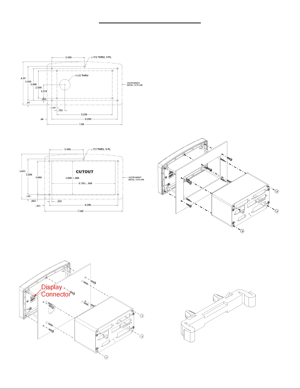
FIG. 1 PANEL HOLE DIMENSIONS
Step 3. Use a phillips head screwdriver and install the five (5) 6-32 x
1/2 inch screws that fasten the bezel to the panel. (See Fig. 3)
Use a torque screw driver and torque each screw to 10 inch/
pounds. DO NOT OVERTIGHTEN!
Step 4. Thread the four (4) threaded rods through the appropriate
holes in the panel and into the bezel. For the retrofit you don’t
have to place the rods through the holes. (See Fig. 4)
Step 5. Hand tighten each rod until you can no longer turn the rod. Do
not force the rods or use pliers of any kind.
Step 6. Put the Display cable and connector through the 1.25-inch
hole in the panel door or cover and plug the display connector
into the display header in the bezel. (See Fig. 3)
Step 7. Gently slide the electronic enclosure onto the threaded rods
while making sure the display cable glides easily into the
enclosure and does not kink. Move the electronic enclosure
toward the panel until it stops. (See Fig. 3)
Step 8. Thread the four (4) 6-32 thumb screws onto the threaded rods
until tight. Do not use pliers on the thumb screws.
FIG. 2 PANEL HOLE DIMENSIONS (RETROFIT)
Step 1. Make sure that all Electrostatic Discharge (ESD) precautions
are taken before and during installation.
Step 2. Use the provided template to make the hole pattern in the
panel door or cover. (Part # 0578-0071-01)
FIG. 4 RETROFIT PANEL MOUNT INSTALL FOR HI 2151/30 &
HI 2110
DIN Rail Installation HI 4050 Weight Controller
Step 1. Snap the DIN rail mounting feet into any of the two holes on
the front panel of the electronic enclosure. (See Figs. 5 & 6)
FIG. 5 DIN RAIL MOUNTING FOOT
FIG. 3 PANEL MOUNT INSTALLATION
Page 2

FIG. 6 VERTICAL AND HORIZONTAL ORIENTATION
Step 2. When installing firmly push the mounting feet until you hear a
snapping sound. The snap means they are mounted correctly.
Step 3. After installation give each mounting foot a little tug to make
sure they are seated correctly.
NOTE: There are several horizontal and vertical mounting
options. It is highly recommended that at least two
mounting feet be used per enclosure.
Step 4. To mount the enclosure onto a DIN rail. Place the mounting
feet on the DIN Rail and firmly press down until the mounting
feet snap onto the rail.
Step 5. To remove the mounting feet use a finger on the clip and gen-
tly pull up on the tab.
NOTE: For Remote Display installation please see Chapter 3,
Installation, of the HI 4050 User’s Guide.
FIG. 8
C2® Load Point Connection
Cable color code for C2 Load Points (left to right facing the rear panel):
• Shield Ground Wire
• C2- Violet
• C2+ Grey
• EXC- Black
• SEN- Brown
• SIG- White
• SIG+ Green
• SEN+ Blue
• EXC+ Red
Step 1. Remove the factory installed jumpers from the terminal block
if you are connecting an 8 wire cable from the junction box.
(See Fig. 8)
Step 2. Connect the cable (Recommended load cell cable: Hardy
Instruments Part # 6020-0001) wires to the Weigh Scale Inputterminal block according to the cable color chart.
Step 3. Plug the terminal block into the Weigh Scale Input connector
on the rear panel.
Step 4. For more information concerning C2 Load Point connection,
consult Chapter 3, Installation, of the HI 4050 User Guide.
Non-C2 Load Point Connection
LOAD POINT INSTALLATION
FIG. 7 REAR PANEL
NOTE: Cable Color Codes vary between vendors, check with your
supplier for the Color Code for your Non-C2 load point. Do
not connect wires to the -C2 and +C2.
Step 1. Remove the factory installed jumpers from the terminal block
if you have a 6-wire load cell cable that includes sense wires
from the load cell or junction box.
Step 2. Connect the cable (Recommended load cell cable: Hardy
Instruments Part # 6020-0001) wires to the Weigh Scale Input
terminal block according to the manufacturer’s specification.
Step 3. Plug the terminal block into the Weigh Scale Input connector
on the rear panel.
Page 3

INPUT POWER WIRING
STARTING THE HI 4050
WARNING: DO NOT PLUG THE POWER CONNECTOR INTO
THE HEADER WITH LIVE POWER. TO DO SO WILL RESULT IN
PROPERTY DAMAGE AND/OR PERSONAL INJURY.
WARNING: IF A LITHIUM BATTERY IS REPLACED WITH AN
INCORRECT TYPE IT MAY CAUSE AN EXPLOSION WHICH WILL
CAUSE PROPERTY DAMAGE OR PERSONAL INJURY.
AC Input Power Wiring (-AC)
WARNING: DO NOT OPERATE WITH INCORRECT LINE VOLT-
AGE. TO DO SO WILL RESULT IN PROPERTY DAMAGE AND/OR
PERSONAL INJURY. MAKE SURE THAT THE POWER SOURCE
DOES NOT EXCEED 240 VAC.
WARNING: IF AN AUTOMATIC DISCONNECT DEVICE IS USED
ON THE AC INPUT WIRES, THE DISCONNECT MUST ACT ON
BOTH THE LINE AND NEUTRAL WIRES IN A DOUBLE POLE, DOU-
BLE THROW ARRANGEMENT I.E. DPDT RELAY. USING OTHER
AUTOMATIC DISCONNECT ARRANGEMENTS MAY CAUSE PERSONAL INJURY AND/OR PROPERTY DAMAGE.
• The AC power should be supplied by a “clean” primary line,
directly from the power panel. This line should not supply any
other equipment, including the feeding unit, and should be
supplied with a minimum 10 amp breaker.
• AC Power Input (See Fig. 7)
Step 1. Connect the power connector (AC or DC) to the HI 4050.
Step 2. The Instrument boots up to the Summary Display. (See Fig. 9)
FIG. 9 SUMMARY DISPLAY
Step 3. Press the Enter button to go to the Configuration menus. (See
Fig. 10)
Neu (Low)
Line (HI)
Earth Ground
Step 1. The HI 4050 is configured with a universal power supply rated
from 110 to 240 VAC.
Step 2. Make sure the VAC power is shut off before installing the
wires to the connector.
Step 3. Install a 3-wire, minimum 14 AWG power line to the 3-pin ter-
minal block connector. Make sure that the shield is connected
to the local Earth Ground connection.
DC Power Input (-DC)
WARNING: DO NOT OPERATE WITH INCORRECT LINE VOLT-
AGE. TO DO SO WILL RESULT IN PROPERTY DAMAGE AND/OR
PERSONAL INJURY. MAKE SURE THAT THE POWER SOURCE
DOES NOT EXCEED 24 VDC.
CAUTION: YOU MUST USE A POWER LIMITED DC POWER
SUPPLY (CLASS 2) ON THE DC INPUT WIRING.
• The DC power should be supplied by a “clean” primary line,
directly from the DC power source.
Step 1. Make sure the VDC power is shut off before installing the
wires to the connector.
Step 2. Connect the 24 VDC Voltage wire, Ground wire and Shield
wire to the connector that plugs into the DC voltage header at
the rear panel. Make sure that the shield is connected to the
local Earth Ground connection.
Step 3. Plug the connector into the header at the rear panel. (See
Fig. 7)
FIG. 10 CONFIGURATION DISPLAY
Step 4. Use the HI 4050 Weight Controller User Guide for Configura-
tion, Operation and Troubleshooting instructions.
9440 Carroll Park Drive, San Diego, CA 92121
Telephone: 1-800-821-5831 FAX: (858) 278-6700
Web Address: http://www.hardysolutions.com
Hardy Process Solutions Document Number: 0596-0304-01 REV C
Copyright August 2011, Hardy Process Solutions, All Rights Reserved.
Printed in the U.S.A.
 Loading...