

Page 1

HI 3000 Series
Operation and Installation Manual
Hardy Process Solutions Document Number: 0596-0258-01 Rev P
Page 2

Local Field Service
Hardy has over 200 field technicians in the U.S., and more positioned throughout the world to assist you in your support needs. We also have factory engineers who will travel to your facility anywhere in the world to help you solve
challenging applications. We're ready to support you with:
• Installation and start-up
• Routine maintenance and certification
• Plant audits and performance measurement
• Emergency troubleshooting and repair
To request Emergency Service and Troubleshooting, Start-up, Installation, Calibration, Verification or to discuss a
Maintenance Agreement please call 800-821-5831 Ext. 1757 or Emergency Service after hours (Standard Hours 6:00
AM to 6:00 PM Pacific Standard Time) and weekends
Ext. 1111.
Outside the U.S
Hardy Process Solutions has built a network of support throughout the globe. For specific field service options available in your area please contact your local sales agent or our U.S. factory at +1 858-292-2710, Ext. 1757.
Page 3

i Table of Contents
Table of Contents
Table of Contents - - - - - - - - - - - - - - - - - - - - - - - - - - - - - - - - - - - - - - - i
Table of Illustrations - - - - - - - - - - - - - - - - - - - - - - - - - - - - - - - - - - - - - - - I
Communications Installation & Operation - - - - - - - - - - - - - - - - - - - - - - - - - - 1
Overview - - - - - - - - - - - - - - - - - - - - - - - - - - - - - - - - - - 1
DeviceNet™ - - - - - - - - - - - - - - - - - - - - - - - - - - - - - - - 1
Hardy Control-Link TCP/IP (Ethernet) - - - - - - - - - - - - - - - - - - 1
PRS-232 Simplex Serial Port - - - - - - - - - - - - - - - - - - - - - - 1
Communication Option Cards - - - - - - - - - - - - - - - - - - - - - - - - 1
Remote I/O - - - - - - - - - - - - - - - - - - - - - - - - - - - - - - - 1
ControlNet - - - - - - - - - - - - - - - - - - - - - - - - - - - - - - - - 2
Profibus - - - - - - - - - - - - - - - - - - - - - - - - - - - - - - - - - 2
MOD-Bus/TPC/IP - - - - - - - - - - - - - - - - - - - - - - - - - - - - 2
OPC - - - - - - - - - - - - - - - - - - - - - - - - - - - - - - - - - - 2
EtherNet/IP™ - - - - - - - - - - - - - - - - - - - - - - - - - - - - - - 3
Allen-Bradley Remote I/O - - - - - - - - - - - - - - - - - - - - - - - - 3
Allen-Bradley License - - - - - - - - - - - - - - - - - - - - - - - - 3
Common Applications - - - - - - - - - - - - - - - - - - - - - - - - 3
Monitoring Weighing Parameters - - - - - - - - - - - - - - - - - - 4
Short Glossary of Terms - - - - - - - - - - - - - - - - - - - - - - - 4
Tare Value - - - - - - - - - - - - - - - - - - - - - - - - - - - - - 4
Remote I/O Board Cable Termination Dip Switch Configuration - - - - - - 4
About Cable Termination - - - - - - - - - - - - - - - - - - - - - - 4
Dip Switch Settings - - - - - - - - - - - - - - - - - - - - - - - - - - - 4
Installing the RIO Option Board - - - - - - - - - - - - - - - - - - - - - 4
Connector Pin Out - - - - - - - - - - - - - - - - - - - - - - - - - - 5
LED Indicators - - - - - - - - - - - - - - - - - - - - - - - - - - - - - - 5
Removing the Remote I/O Option Card - - - - - - - - - - - - - - - - - - - - 5
Remote I/O Configuration Procedures from the Front Panel - - - - - - - 5
Remote I/O Configuration Procedures from the Web Page - - - - - - - - 7
Discrete Remote I/O Mapping - - - - - - - - - - - - - - - - - - - - - - 9
About Discrete Remote I/O Mapping - - - - - - - - - - - - - - - - - 9
General Information - - - - - - - - - - - - - - - - - - - - - - - - - 9
For Reads: - - - - - - - - - - - - - - - - - - - - - - - - - - - - - 9
Mapping - - - - - - - - - - - - - - - - - - - - - - - - - - - - - - - - - - - 10
Cabling Installation - - - - - - - - - - - - - - - - - - - - - - - - - - - - - - - - - 11
General Introduction to Cabling - - - - - - - - - - - - - - - - - - - - - - - 11
Unpacking - - - - - - - - - - - - - - - - - - - - - - - - - - - - - - - - - - 11
Input Power Wiring - - - - - - - - - - - - - - - - - - - - - - - - - - - - - 11
Digital Input Wiring - - - - - - - - - - - - - - - - - - - - - - - - - - - - - 11
Output Relay Wiring - - - - - - - - - - - - - - - - - - - - - - - - - - - - - 12
Load Point Connections - - - - - - - - - - - - - - - - - - - - - - - - - - - 12
-JB Option Wiring - - - - - - - - - - - - - - - - - - - - - - - - - - - - - - 13
Ethernet Cable Connection and Setup - - - - - - - - - - - - - - - - - - - - 13
DeviceNet Connection and Setup From the Front Panel - - - - - - - - - - - 16
®
C2
Load Point Connection - - - - - - - - - - - - - - - - - - - - - - - 12
Non-C2 Load Cell Connection - - - - - - - - - - - - - - - - - - - - - - 12
RS 232 Connection - - - - - - - - - - - - - - - - - - - - - - - - - - - 12
RS 232 Connection Pinout - - - - - - - - - - - - - - - - - - - - - - 13
Setting the IP Address for the Blind Remote - - - - - - - - - - - - - - - 15
Setting or Changing the IP Address using the Ethernet - - - - - - - - 15
For HI 3010 Only - - - - - - - - - - - - - - - - - - - - - - - - - - 16
For HI 3030, HI 3600, HI 3300 - - - - - - - - - - - - - - - - - - - - 17
Page 4

HI 3000 Series ii
User Guide
ControlNet Option Card Installation - - - - - - - - - - - - - - - - - - - - - - 18
Removing the ControlNet Option Card - - - - - - - - - - - - - - - - - - - - 19
ControlNet Connection and Setup - - - - - - - - - - - - - - - - - - - - - - 19
Hardware Requirements: - - - - - - - - - - - - - - - - - - - - - - - - 19
Software Requirements: - - - - - - - - - - - - - - - - - - - - - - - - - 19
Setting the ControlNet Node Address from the Front Panel - - - - - - - - 20
Activating ControlNet and Setting the ControlNet Node Address
from the Web Page - - - - - - - - - - - - - - - - - - - - - - - - - - - 20
LED Status Indicators - - - - - - - - - - - - - - - - - - - - - - - - - - 22
EtherNet/IP™ Option Card Installation - - - - - - - - - - - - - - - - - - - - 22
Removing the EtherNet/IP Option Card - - - - - - - - - - - - - - - - - - - - 23
Setting Up the EtherNet I/P Address from the Front Panel - - - - - - - - 23
Setting Up the EtherNet I/P Address from the Web Page - - - - - - - - - 24
LED Status Indicators - - - - - - - - - - - - - - - - - - - - - - - - - - 25
LED 1 - Link (Activity) - - - - - - - - - - - - - - - - - - - - - - - - 25
LED 2 - Module Status - - - - - - - - - - - - - - - - - - - - - - - - 25
LED 3 - Network Status - - - - - - - - - - - - - - - - - - - - - - - 26
LED 4 - Activity - - - - - - - - - - - - - - - - - - - - - - - - - - - 26
Profibus Option Card Installation - - - - - - - - - - - - - - - - - - - - - - - 26
Profibus Connection and Setup - - - - - - - - - - - - - - - - - - - - - - - 26
Hardware Requirements: - - - - - - - - - - - - - - - - - - - - - - - - 26
Software Requirements: - - - - - - - - - - - - - - - - - - - - - - - - - 26
Cabling Guidelines - - - - - - - - - - - - - - - - - - - - - - - - - 26
Cable Specification - - - - - - - - - - - - - - - - - - - - - - - - - 27
LED Indicators - - - - - - - - - - - - - - - - - - - - - - - - - - - - - - 28
Removing the Profibus Option Card - - - - - - - - - - - - - - - - - - - - - 28
Analog Output Option Card Installation - - - - - - - - - - - - - - - - - - - - 28
Electrical Connection - - - - - - - - - - - - - - - - - - - - - - - - - - 29
Removing the Analog Option Card - - - - - - - - - - - - - - - - - - - - - - 29
Rear Cover Installation (HI 3000-RC) - - - - - - - - - - - - - - - - - - - - - 29
Removing the NEMA 4 Plug - - - - - - - - - - - - - - - - - - - - - - - 30
Installing the NEMA 4 Plug - - - - - - - - - - - - - - - - - - - - - - - - 30
Installing the Cord Grip Assemblies - - - - - - - - - - - - - - - - - - - 30
Removing the Cord Grip Assembly - - - - - - - - - - - - - - - - - - - - 32
Installing the HI 3000-RC Rear Cover - - - - - - - - - - - - - - - - - - - - 32
Network Installation - - - - - - - - - - - - - - - - - - - - - - - - - - - - - - - - - 35
About Networks - - - - - - - - - - - - - - - - - - - - - - - - - - - - - - - 35
Simple Ethernet Network - - - - - - - - - - - - - - - - - - - - - - - - - - 35
Materials Required - - - - - - - - - - - - - - - - - - - - - - - - - - - 35
Hardy Control-Link Ethernet Network - - - - - - - - - - - - - - - - - - - - - 37
Materials Required - - - - - - - - - - - - - - - - - - - - - - - - - 37
Setting Node Addresses for HI 3000 Series Instruments from the Browser 38
Using the Ping Tool - - - - - - - - - - - - - - - - - - - - - - - - - - - - - 40
DeviceNet Network Setup - - - - - - - - - - - - - - - - - - - - - - - - - - 41
RSNetWorx Setup for HI 3000 Series Instruments - - - - - - - - - - - - 41
Slave Mode Setup - - - - - - - - - - - - - - - - - - - - - - - - - - - - - - 43
Building a Scanlist in RSNetWorx - - - - - - - - - - - - - - - - - - - - - - 45
ControlNet Network Setup - - - - - - - - - - - - - - - - - - - - - - - - - - 46
RSNetWorx Setup for HI 3000 Series Instruments with ControlNet
Option Card - - - - - - - - - - - - - - - - - - - - - - - - - - - - - - - 46
Schedule the Network Using RSNetWorx for ControlNet - - - - - - - - - 47
Verify the Network Properties - - - - - - - - - - - - - - - - - - - - 47
Survey the Network for Connected Devices - - - - - - - - - - - - - 47
Schedule the Network and Save the Configuration - - - - - - - - - - 47
Selecting the ControlNet Node Address from the Front Panel - - - - - - - 47
Selecting the ControlNet Node Address from the Web Page - - - - - - - 48
Page 5

iii Table of Contents
PROFIBUS-DP Network Setup - - - - - - - - - - - - - - - - - - - - - - - - 49
Initialization Process - - - - - - - - - - - - - - - - - - - - - - - - - - - - - 49
Profibus-DP .GSD File - - - - - - - - - - - - - - - - - - - - - - - - - - 49
Pre-Initialization Procedures - - - - - - - - - - - - - - - - - - - - - - - 49
Initialization Procedures - - - - - - - - - - - - - - - - - - - - - - - - - 50
Selecting the Profibus Node Address from the Front Panel - - - - - - - - 52
Selecting the Profibus Node Address from the Web Page - - - - - - - - 53
MODBUS - TCP/IP Over Ethernet - - - - - - - - - - - - - - - - - - - - - - 54
About MODBUS/TCP/IP Over Ethernet - - - - - - - - - - - - - - - - - 54
Installing MODBUS - - - - - - - - - - - - - - - - - - - - - - - - - - - 55
Enabling MODBUS in the HI 3000 Module - - - - - - - - - - - - - - 55
Installing Hardy Modbus-Link - - - - - - - - - - - - - - - - - - - - 56
Using MODBUS with Excel
®
- - - - - - - - - - - - - - - - - - - - - - - 60
OPC Network Setup - - - - - - - - - - - - - - - - - - - - - - - - - - - - - 60
OPC SERVER - - - - - - - - - - - - - - - - - - - - - - - - - - - 61
Configuring Omniserver to Communicate with an HI 3000 Module - - 61
Setting Up OPC Communication with a Client - - - - - - - - - - - - - - 72
About OPC Clients - - - - - - - - - - - - - - - - - - - - - - - - - 72
Setting up the Output to the OPC Server and the Client from the
HI 3000 Module - - - - - - - - - - - - - - - - - - - - - - - - - - - - - 77
Adding the HI 3000 Module to the Hardy Control-Link (TCP/IP) Network - 77
Mapping Parameters to the HardyFloat Output Table - - - - - - - - - - - 79
Configuring EtherNet/IP Using RSLogix5000
®
- - - - - - - - - - - - - - - - 83
Mapping - - - - - - - - - - - - - - - - - - - - - - - - - - - - - - - - - - - 85
E-Mail Configuration and Operation - - - - - - - - - - - - - - - - - - - - - - - - 87
Overview - - - - - - - - - - - - - - - - - - - - - - - - - - - - - - - - - - 87
Understanding IP Addresses - - - - - - - - - - - - - - - - - - - - - - - - - 87
Glossary of E-Mail Terms - - - - - - - - - - - - - - - - - - - - - - - - - - 87
Gateway - - - - - - - - - - - - - - - - - - - - - - - - - - - - - - - - 87
SMTP - - - - - - - - - - - - - - - - - - - - - - - - - - - - - - - - - - 88
DNS - - - - - - - - - - - - - - - - - - - - - - - - - - - - - - - - - - - 88
POP - - - - - - - - - - - - - - - - - - - - - - - - - - - - - - - - - - - 88
Configuring the E-Mail Server - - - - - - - - - - - - - - - - - - - - - - - - 88
Entering the Mail Server Name from the Front Panel - - - - - - - - - 89
Continuing E-Mail Configuration from the Web Page - - - - - - - - - 90
Configuring Standard E-Mail - - - - - - - - - - - - - - - - - - - - - - - 90
Configuring Custom E-Mail - - - - - - - - - - - - - - - - - - - - - - - 91
About Custom E-Mail - - - - - - - - - - - - - - - - - - - - - - - - 91
About Tokens - - - - - - - - - - - - - - - - - - - - - - - - - - - - 91
Testing E-Mail - - - - - - - - - - - - - - - - - - - - - - - - - - - - - - 94
Setting up Filters in E-mail Applications - - - - - - - - - - - - - - - - - - - 95
Security Setup - - - - - - - - - - - - - - - - - - - - - - - - - - - - - - - - - - - - 97
Overview - - - - - - - - - - - - - - - - - - - - - - - - - - - - - - - - - - 97
Security Levels - - - - - - - - - - - - - - - - - - - - - - - - - - - - - - - 97
Setting up Passwords from the Front Panel - - - - - - - - - - - - - - - - - 97
Setting up Passwords from the Browser - - - - - - - - - - - - - - - - - - - 98
Log On Procedures - - - - - - - - - - - - - - - - - - - - - - - - - - - - - 99
Logging on from the Front Panel - - - - - - - - - - - - - - - - - - - - - 99
Log On from the Browser - - - - - - - - - - - - - - - - - - - - - - - - 100
Log Off Procedures from the Front Panel - - - - - - - - - - - - - - - - - 100
HI 3001 Master Display - - - - - - - - - - - - - - - - - - - - - - - - - - - - - - - 103
Overview - - - - - - - - - - - - - - - - - - - - - - - - - - - - - - - - - - 103
Getting Started - - - - - - - - - - - - - - - - - - - - - - - - - - - - - - - 103
Help - - - - - - - - - - - - - - - - - - - - - - - - - - - - - - - - - - - - - 103
Page 6

Glossary of terms
Index
HI 3000 Series iv
User Guide
About Help - - - - - - - - - - - - - - - - - - - - - - - - - - - - - - - 103
Front Panel Display - - - - - - - - - - - - - - - - - - - - - - - - - - - 103
Button Functions - - - - - - - - - - - - - - - - - - - - - - - - - - - - 103
Start Button - - - - - - - - - - - - - - - - - - - - - - - - - - - - - 103
Stop Button - - - - - - - - - - - - - - - - - - - - - - - - - - - - - 103
Help Button - - - - - - - - - - - - - - - - - - - - - - - - - - - - - 103
Station Button - - - - - - - - - - - - - - - - - - - - - - - - - - - - 103
Buttons Button - - - - - - - - - - - - - - - - - - - - - - - - - - - - 104
Setup/3/DEF Button - - - - - - - - - - - - - - - - - - - - - - - - - 104
Test/9/WXYZ Button - - - - - - - - - - - - - - - - - - - - - - - - - 104
Setting the IP Address - - - - - - - - - - - - - - - - - - - - - - - - - - - - 104
Installing the HI 3001 - - - - - - - - - - - - - - - - - - - - - - - - - - - - 104
Selecting an Instrument on the Network - - - - - - - - - - - - - - - - - - - 104
Software Downloads for HI 3000 Series - - - - - - - - - - - - - - - - - - - 104
Page 7

I Table of Illustrations
Table of Illustrations
Communications Installation & Operation - - - - - - - - - - - - - - - - - - - - - - - - - - 1
FIG. 1 CONTROLNET ARCHITECTURE - - - - - - - - - - - - - - - - - 2
FIG. 2 ETHERNET/IP™ NETWORK - - - - - - - - - - - - - - - - - - - - 3
FIG. 3 TERMINATING SWITCH FOR TERMINATING LAST MODULE - - - 4
FIG. 4 REMOTE I/O OPTION CARD - - - - - - - - - - - - - - - - - - - 4
FIG. 5 REMOTE I/O/SLIDE INTO OPTION SLOT #0 - - - - - - - - - - - - 5
FIG. 6 REMOTE I/O OPTION CARD INSTALLED - - - - - - - - - - - - - 5
FIG. 7 CONFIGURATION MENU/SELECTING SETUP - - - - - - - - - - 5
FIG. 8 CONFIGURATION MENU/SELECTING OPTIONS - - - - - - - - - 6
FIG. 9 OPTIONS/SELECTING REMOTE I/O - - - - - - - - - - - - - - - - 6
FIG. 10 REMOTE I/O MENU/SETTING PARAMETERS - - - - - - - - - - - 6
FIG. 11 REMOTE I/O/SETTING RACK SIZE - - - - - - - - - - - - - - - - 6
FIG. 12 REMOTE I/O SELECTING STARTING QUARTER - - - - - - - - - 6
FIG. 13 INSTRUMENT HOME PAGE/SELECTING CONFIGURATION - - - 7
FIG. 14 CONFIGURATION - OPTIONS PAGE/SELECTING VIEW
REMOTE I/O CONFIGURATION - - - - - - - - - - - - - - - - - - - - - - - 7
FIG. 15 REMOTE I/O CONFIGURATION PAGE - - - - - - - - - - - - - - 7
FIG. 16 REMOTE I/O CONFIGURATION/SELECTING BAUD RATE - - - - 7
FIG. 17 REMOTE I/O CONFIGURATION/SELECTING RACK SIZE - - - - - 8
FIG. 18 REMOTE I/0 CONFIGURATION/SELECTING QUARTER - - - - - - 8
FIG. 19 REMOTE I/O CONFIGURATION/SELECTING LAST QUARTER - - 8
Cabling Installation - - - - - - - - - - - - - - - - - - - - - - - - - - - - - - - - - 11
FIG. 20 POWER WIRING DIAGRAM - - - - - - - - - - - - - - - - - - - - 11
FIG. 21 POWER SUPPLY BOARD REAR PANEL - - - - - - - - - - - - - 11
FIG. 22 DRY CONTACT WIRING DIAGRAM - - - - - - - - - - - - - - - - 12
FIG. 23 REAR PANEL/LOAD POINT CONNECTIONS - - - - - - - - - - - 12
FIG. 24 SERIAL PORT CONNECTION - - - - - - - - - - - - - - - - - - - 13
FIG. 25 -JB OPTION CONNECTIONS - - - - - - - - - - - - - - - - - - - 13
FIG. 26 REAR PANEL/ETHERNET RJ 45 CONNECTION - - - - - - - - - - 13
FIG. 27 CONFIGURATION MENU/SELECTION SETUP - - - - - - - - - - 14
FIG. 28 SETUP MENU - - - - - - - - - - - - - - - - - - - - - - - - - - - 14
FIG. 29 SETUP MENU/ETHERNET SUB-MENU - - - - - - - - - - - - - - 14
FIG. 30 ETHERNET MENU/DEFAULT IP ADDRESS - - - - - - - - - - - - 14
FIG. 31 ENTER IP ADDRESS IN BROWSER ADDRESS FIELD - - - - - - 14
FIG. 32 WEB PAGE - - - - - - - - - - - - - - - - - - - - - - - - - - - - 15
FIG. 33 INSTRUMENT WEB PAGE - - - - - - - - - - - - - - - - - - - - - 15
FIG. 34 IP SETUP MENU - - - - - - - - - - - - - - - - - - - - - - - - - 15
FIG. 35 IP SETUP/SETTING NEW ADDRESS - - - - - - - - - - - - - - - 15
FIG. 36 NEW IP ADDRESS IS RESET - - - - - - - - - - - - - - - - - - - 16
FIG. 37 REAR PANEL/DEVICENET CONNECTION - - - - - - - - - - - - 16
FIG. 38 CONFIGURATION MENU/SELECTING SETUP - - - - - - - - - - 16
FIG. 39 SETUP MENU/SELECTING DEVICENET - - - - - - - - - - - - - 16
FIG. 40 DEVICENET SUB-MENU/SETTING THE BAUD RATE - - - - - - - 16
FIG. 41 DEVICENET/SELECTING NODE ADDRESS - - - - - - - - - - - - 17
FIG. 42 CONFIGURATION MENU/SELECTING SETUP - - - - - - - - - - 17
FIG. 43 CONFIGURATION MENU - - - - - - - - - - - - - - - - - - - - - 17
FIG. 44 OPTIONS MENU/SELECTING DEVICENET I/O - - - - - - - - - - 17
FIG. 45 DEVICENET SUB-MENU/SETTING THE BAUD RATE - - - - - - - 17
FIG. 46 DEVICENET/SELECTING NODE ADDRESS - - - - - - - - - - - - 18
FIG. 47 CONTROLNET/OPTION CARD - - - - - - - - - - - - - - - - - - 18
FIG. 48 CONTROLNET/SLIDE INTO OPTION SLOT #0 - - - - - - - - - - 18
FIG. 49 CONTROLNET OPTION CARD INSTALLED - - - - - - - - - - - - 19
FIG. 50 CONTROLNET CABLE ASSEMBLIES - - - - - - - - - - - - - - - 19
FIG. 51 ROTARY SWITCHES/SETTING NODE ADDRESS TO 0, 0 - - - - - 19
Page 8

HI 3000 Series II
Operation and Installation
FIG. 52 REAR PANEL CONTROLNET CONNECTORS AND LEDS - - - - - 19
FIG. 53 CONFIGURATION MENU/SELECTING SETUP - - - - - - - - - - 20
FIG. 54 CONFIGURATION MENU/SELECTING OPTIONS - - - - - - - - - 20
FIG. 55 OPTIONS/SELECTING CONTROLNET I/O - - - - - - - - - - - - - 20
FIG. 56 CONTROLNET I/O MENU/SETTING NODE ADDRESS - - - - - - - 20
FIG. 57 HOME PAGE/SELECTING CONFIGURATION - - - - - - - - - - - 20
FIG. 58 CONFIGURATION PAGE/SELECTING OPTIONS - - - - - - - - - 21
FIG. 59 OPTIONS PAGE/SELECTING VIEW CONTROLNET
CONFIGURATION - - - - - - - - - - - - - - - - - - - - - - - - - - - - - - 21
FIG. 60 CONTROLNET PAGE/ACTIVATING CONTROLNET - - - - - - - - 21
FIG. 61 CONTROLNET CONFIGURATION PAGE/ENTERING
NODE ADDRESS - - - - - - - - - - - - - - - - - - - - - - - - - - - - - - 21
FIG. 62 CONTROLNET CONFIGURATION/ENTERING NODE
ADDRESS - - - - - - - - - - - - - - - - - - - - - - - - - - - - - - - - - - 22
FIG. 63 ETHERNET I/P/OPTION CARD - - - - - - - - - - - - - - - - - - 23
FIG. 64 ETHERNET/I/P/SLIDE INTO OPTION SLOT #0 - - - - - - - - - - - 23
FIG. 65 ETHERNET/IP OPTION CARD INSTALLED - - - - - - - - - - - - 23
FIG. 66 CONFIGURATION MENU/SELECTING OPTIONS - - - - - - - - - 24
FIG. 67 OPTIONS/SELECTING ETHERNET/IP I/O - - - - - - - - - - - - - 24
FIG. 68 ETHERNET/IP MENU/SETTING IP ADDRESS - - - - - - - - - - - 24
FIG. 69 HI 3000 HOME PAGE/SELECTING CONFIGURATION - - - - - - - 24
FIG. 70 CONFIGURATION PAGE/SELECTING OPTIONS - - - - - - - - - 25
FIG. 71 OPTIONS PAGE/SELECTING VIEW ETHERNET/IP
CONFIGURATION - - - - - - - - - - - - - - - - - - - - - - - - - - - - - - 25
FIG. 72 ETHERNET/IP PAGE/SETTING IP ADDRESS - - - - - - - - - - - 25
FIG. 73 CONNECTOR/DIP SWITCHES/LEDS - - - - - - - - - - - - - - - 25
FIG. 74 PROFIBUS DB9 SERIAL CONNECTOR WITH SLIDE
SWITCH/MALE - - - - - - - - - - - - - - - - - - - - - - - - - - - - - - - 26
FIG. 75 DB9 CONNECTOR ON THE HARDY PROFIBUS OPTION CARD - - 27
FIG. 76 ROTARY SWITCHES/SETTING NODE ADDRESS TO 0, 0 - - - - - 27
FIG. 77 LED INDICATORS - - - - - - - - - - - - - - - - - - - - - - - - - 28
FIG. 78 ANALOG OUTPUT OPTION 2AN - - - - - - - - - - - - - - - - - - 29
FIG. 79 INSTALLING THE ANALOG OPTION CARD IN A 3000 CHASSIS - 29
FIG. 80 ANALOG ELECTRICAL CONNECTIONS - - - - - - - - - - - - - - 29
FIG. 81 NEMA 4X REAR COVER - - - - - - - - - - - - - - - - - - - - - - 30
FIG. 82 INSTALLING NEMA 4 PLUG - - - - - - - - - - - - - - - - - - - - 30
FIG. 83 INSTALLING THE HEX NUT ONTO THE CORD GRIP ASSEMBLY - 30
FIG. 84 CORD GRIP INSTALLED - - - - - - - - - - - - - - - - - - - - - 31
FIG. 85 INSTALLING THE HEX NUT ONTO THE CORD GRIP ASSEMBLY - 31
FIG. 86 CORD GRIP INSTALLED - - - - - - - - - - - - - - - - - - - - - 31
FIG. 87 INSTALLING CABLES IN THE CORD GRIP ASSEMBLY - - - - - - 32
FIG. 88 ALIGNING THE REAR COVER TO THE CHASSIS - - - - - - - - - 32
FIG. 89 REAR COVER, NEMA 4 PLUGS, AND CORD GRIPS INSTALLED - 33
Network Installation - - - - - - - - - - - - - - - - - - - - - - - - - - - - - - - - - 35
FIG. 90 SIMPLE HARDY CONTROL-LINK NETWORK - - - - - - - - - - - 35
FIG. 91 IP ADDRESS CONFIGURATION - - - - - - - - - - - - - - - - - - 35
FIG. 92 CONTROL PANEL - - - - - - - - - - - - - - - - - - - - - - - - - 36
FIG. 93 NETWORK DIALOG BOX/SELECT TCP/IP - - - - - - - - - - - - - 36
FIG. 94 NETWORK DIALOG BOX/SELECT PROPERTIES - - - - - - - - - 37
FIG. 95 TCI/IP PROPERTIES/IP ADDRESS - - - - - - - - - - - - - - - - 37
FIG. 96 INTERNET PROPERTIES DIALOG BOX - - - - - - - - - - - - - - 37
FIG. 97 HARDY CONTROL-LINK ETHERNET NETWORK - - - - - - - - - 37
FIG. 98 FILLER/DISPENSER HOME PAGE/SELECTING
CONFIGURATION - - - - - - - - - - - - - - - - - - - - - - - - - - - - - - 38
FIG. 99 CONFIGURATION PAGE/SELECTING HARDY CONTROL-LINK - - 38
FIG. 100 CONFIGURATION - HARDY CONTROL-LINK PAGE - - - - - - - - 38
Page 9

III Table of Illustrations
FIG. 101 CONFIGURATION - HARDY CONTROL-LINK/INSTRUMENT
SELECTION PULL DOWN LIST - - - - - - - - - - - - - - - - - - - - - - - 39
FIG. 102 CONFIGURATION PAGE WITH INSTRUMENTS NOT
ASSIGNED A NODE ADDRESS - - - - - - - - - - - - - - - - - - - - - - - 39
FIG. 103 SELECTED INSTRUMENT WITH IP ADDRESS IN
IP ADDRESS FIELD - - - - - - - - - - - - - - - - - - - - - - - - - - - - - 39
FIG. 104 HI-3010 (IP ADDRESS 192.168.110.68) ASSIGNED TO NODE 0 - - 39
FIG. 105 SELECTED INSTRUMENT WITH IP ADDRESS IN IP ADDRESS
FIELD - - - - - - - - - - - - - - - - - - - - - - - - - - - - - - - - - - - - 39
FIG. 106 HI-3010 (IP ADDRESS 192.168.110.24) ASSIGNED TO NODE 1 - - 40
FIG. 107 INSTRUMENTS ASSIGNED TO NODE 0 THROUGH NODE 7 - - - 40
FIG. 108 SAVING THE CONFIGURATION - - - - - - - - - - - - - - - - - - 40
FIG. 109 TRANSFERRING THE NODE CONFIGURATION FROM
NODE 0 TO NODE 1 - - - - - - - - - - - - - - - - - - - - - - - - - - - - 40
FIG. 110 SELECTING EDS WIZARD - - - - - - - - - - - - - - - - - - - - 41
FIG. 111 EDS WIZARD DIALOG BOX - - - - - - - - - - - - - - - - - - - - 41
FIG. 112 SELECTING “REGISTER AN EDS FILE” - - - - - - - - - - - - - - 41
FIG. 113 SELECTING THE HARDY EDS FILE - - - - - - - - - - - - - - - - 41
FIG. 114 SELECTING THE HARDY EDS FILE - - - - - - - - - - - - - - - - 42
FIG. 115 EDS FILE INSTALLATION TEST RESULTS DIALOG BOX - - - - - 42
FIG. 116 CHANGE GRAPHIC IMAGE DIALOG BOX - - - - - - - - - - - - - 42
FIG. 117 FINAL TASK SUMMARY DIALOG BOX - - - - - - - - - - - - - - 42
FIG. 118 HARDWARE/VENDOR/HARDY INSTRUMENTS INC. INSTALLED - 43
FIG. 119 GRAPH/HARDY FILLER ICON - - - - - - - - - - - - - - - - - - - 43
FIG. 120 MODULE TAB/SELECTING SLAVE MODE - - - - - - - - - - - - - 43
FIG. 121 SLAVE MODE DIALOG BOX - - - - - - - - - - - - - - - - - - - - 43
FIG. 122 INPUT PAGE/SELECTING AUTOMAP - - - - - - - - - - - - - - - 44
FIG. 123 INPUT PAGE/INPUTS MAPPED - - - - - - - - - - - - - - - - - - 44
FIG. 124 OUTPUT PAGE/SELECTING AUTOMAP - - - - - - - - - - - - - - 44
FIG. 125 OUTPUT PAGE/OUTPUTS MAPPED - - - - - - - - - - - - - - - 44
FIG. 126 GRAPH OF NETWORKED MODULES - - - - - - - - - - - - - - - 45
FIG. 127 HARDY FILLER PROPERTIES LIST - - - - - - - - - - - - - - - - 45
FIG. 128 SCANLIST PAGE/AVAILABLE DEVICES - - - - - - - - - - - - - - 45
FIG. 129 SCANLIST PAGE/SCANLIST - - - - - - - - - - - - - - - - - - - 46
FIG. 130 INPUT PAGE/CHANGE PARAMETERS - - - - - - - - - - - - - - 46
FIG. 131 CONFIGURATION MENU/SELECTING SETUP - - - - - - - - - - 47
FIG. 132 CONFIGURATION MENU/SELECTING OPTIONS - - - - - - - - - 48
FIG. 133 OPTIONS/SELECTING REMOTE I/O - - - - - - - - - - - - - - - - 48
FIG. 134 CONTROLNET I/0 MENU/SELECTING THE NODE ADDRESS - - - 48
FIG. 135 ELECTING CONFIGURATION FROM THE HOME
PAGE OF THE HI 3000 INSTRUMENT - - - - - - - - - - - - - - - - - - - 48
FIG. 136 CONFIGURATION PAGE/SELECTING OPTIONS - - - - - - - - - 48
FIG. 137 CONFIGURATION - OPTIONS/SELECTING VIEW
CONTROLNET CONFIGURATION OPTION - - - - - - - - - - - - - - - - - 49
FIG. 138 CONTROLNET CONFIGURATION PAGE/SELECTING
THE NODE ADDRESS - - - - - - - - - - - - - - - - - - - - - - - - - - - 49
FIG. 139 PROFIBUS LOGO - - - - - - - - - - - - - - - - - - - - - - - - - 49
FIG. 140 SIMPLE PROFIBUS NETWORK WITH TRUNK AND DROP LINES - 49
FIG. 141 HARDWARE CATALOG/SELECTING ANYBUS-S PDP FOLDER - - 50
FIG. 142 ANYBUS-S PDP PARAMETERS DIALOG BOX - - - - - - - - - - - 50
FIG. 143 SELECTING THE INPUT AND OUTPUT SIZE - - - - - - - - - - - 51
FIG. 144 ANYBUS-S PDP APPEARS IN THE NETWORK - - - - - - - - - - 51
FIG. 145 DOWNLOADING HI 3000 SERIES CONFIGURATION - - - - - - - 51
FIG. 146 SELECT DESTINATION MODULE DIALOG BOX - - - - - - - - - - 52
FIG. 147 SELECT STATION ADDRESS DIALOG BOX 52
FIG. 148 DOWNLOADING CONFIGURATION PROMPT - - - - - - - - - - - 52
FIG. 149 INITIALIZATION COMPLETE - - - - - - - - - - - - - - - - - - - 52
Page 10

HI 3000 Series IV
Operation and Installation
FIG. 150 CONFIGURATION MENU/SELECTING SETUP - - - - - - - - - - 52
FIG. 151 CONFIGURATION MENU/SELECTING OPTIONS - - - - - - - - - 53
FIG. 152 OPTIONS/SELECTING PROFIBUS I/0 - - - - - - - - - - - - - - - 53
FIG. 153 PROFIBUS I/0 MENU/SELECTING THE NODE ADDRESS - - - - - 53
FIG. 154 SELECTING CONFIGURATION FROM THE HOME
PAGE OF THE HI 3000 INSTRUMENT - - - - - - - - - - - - - - - - - - - 53
FIG. 155 CONFIGURATION PAGE/SELECTING OPTIONS - - - - - - - - - 53
FIG. 156 CONFIGURATION - OPTIONS/SELECTING VIEW
PROFIBUS CONFIGURATION OPTION - - - - - - - - - - - - - - - - - - - 54
FIG. 157 PROFIBUS CONFIGURATION PAGE/SELECTING THE
NODE ADDRESS - - - - - - - - - - - - - - - - - - - - - - - - - - - - - - 54
FIG. 158 MODBUS COMMUNICATION DIAGRAM - - - - - - - - - - - - - - 55
FIG. 159 MACHINE MONITOR/SELECTING CONFIGURATION - - - - - - - 55
FIG. 160 CONFIGURATION/SELECTING OPTIONS - - - - - - - - - - - - - 55
FIG. 161 CONFIGURATION - OPTIONS/SELECTING MODBUS - - - - - - - 55
FIG. 162 MODBUS - OPTIONS PAGE - - - - - - - - - - - - - - - - - - - - 55
FIG. 163 MODBUS - OPTIONS/ENABLED] - - - - - - - - - - - - - - - - - 56
FIG. 164 HARDY MODBUS-LINK DISPLAY - - - - - - - - - - - - - - - - - 56
FIG. 165 HARDY MODBUS-LINK/SELECTING CONNECT - - - - - - - - - - 56
FIG. 166 TCP/IP CONNECTION DISPLAY - - - - - - - - - - - - - - - - - - 57
FIG. 167 TCP/IP CONNECTION DISPLAY/SELECTING TCP/IP - - - - - - - 57
FIG. 168 TCP/IP CONNECTION DISPLAY/ENTERING THE IP ADDRESS - - 57
FIG. 169 MAPPING DISPLAY/CLICKING ON DESTINATION SCRATCHPAD: HFO4 (HARDY FLOAT OUT - WORD 4) - - - - - - - - - - 57
FIG. 170 MAPPING DISPLAY/SELECTING DESTINATION SCRATCHPAD: HFO4 - - - - - - - - - - - - - - - - - - - - - - - - - - - - 57
FIG. 171 MAPPING DISPLAY/SELECTING SOURCE MFI0 (MODBUS FLOAT IN - WORD 0) - - - - - - - - - - - - - - - - - - - - 58
FIG. 172 MAPPING DISPLAY/MAPPING THE SOURCE TO THE
DESTINATION - - - - - - - - - - - - - - - - - - - - - - - - - - - - - - - 58
FIG. 173 MAPPING DISPLAY/HFO - FLOAT VARIABLES/ENTERING
A VALUE FOR WORD 0 - - - - - - - - - - - - - - - - - - - - - - - - - - - 58
FIG. 174 HARDY MODBUS-LINK DISPLAY/SELECTING DISPLAY/FLOAT
INVERSE - - - - - - - - - - - - - - - - - - - - - - - - - - - - - - - - - - 58
FIG. 175 HARDY MODBUS-LINK DISPLAY/555.0000 APPEARS - - - - - - - 59
FIG. 176 HARDY MODBUS-LINK DISPLAY/SELECTING BUTTON 23 READ/WRITE MULTIPLE REGISTERS - - - - - - - - - - - - - - - - - - - 59
FIG. 177 HARDY MODBUS-LI NK DISPLAY/WRITER MULTIPLE
REGISTERS DISPLAY - - - - - - - - - - - - - - - - - - - - - - - - - - - 59
FIG. 178 HARDY MODBUS-LINK/ENTER VALUE DISPLAY - - - - - - - - - 59
FIG. 179 HARDY MODBUS-LINK/ENTER VALUE DISPLAY/ENTERING 999 - 59
FIG. 180 HARDY MODBUS-LINK/WRITE MULTIPLE
REGISTERS/SENDING NEW VALUE - - - - - - - - - - - - - - - - - - - - 60
FIG. 181 RESPONSE OK POP UP - - - - - - - - - - - - - - - - - - - - - - 60
FIG. 182 MAPPING DISPLAY WITH VALUE “999.0000” RECEIVED
FROM THE HARDY MODBUS-LINK CLIENT - - - - - - - - - - - - - - - - 60
FIG. 183 OPC HETEROGENEOUS COMPUTING ENVIRONMENT - - - - - 61
FIG. 184 OPC CLIENT/SERVER/ITEMS - - - - - - - - - - - - - - - - - - - 61
FIG. 185 OMNISERVER CONFIGURATION DIALOG BOX - - - - - - - - - - 61
FIG. 186 OMNISERVER CONFIGURATION DIALOG BOX - - - - - - - - - - 62
FIG. 187 WINSOCK DEVICE CONFIGURATION/DEFAULT PARAMETERS - 62
FIG. 188 WINSOCK CONFIGURATION/ENTERING HI 3000 SETUP
PARAMETERS - - - - - - - - - - - - - - - - - - - - - - - - - - - - - - - 62
FIG. 189 PINGING HI 3000 MODULE/CONNECTION INDICATED - - - - - - 62
FIG. 190 HI 3000 DEVICE ICON WITH IP ADDRESS - - - - - - - - - - - - 63
FIG. 191 PROTOCOLS DIALOG BOX - - - - - - - - - - - - - - - - - - - - 63
FIG. 192 PROTOCOL DEFINITION/DOUBLE OR RIGHT CLICK ON
Page 11

V Table of Illustrations
PROTOCOL SETTINGS - - - - - - - - - - - - - - - - - - - - - - - - - - - 63
FIG. 193 PROTOCOLS DEFINITION DIALOG BOX/CREATING
PROTOCOL NAME AND DESCRIPTION - - - - - - - - - - - - - - - - - - 63
FIG. 194 PROTOCOL DEFINITION/BINARY FORMATS PAGE - - - - - - - 64
FIG. 195 PROTOCOLS DEFINITION - - - - - - - - - - - - - - - - - - - - 64
FIG. 196 PROTOCOL SETTINGS WITH NEW PROTOCOL DEFINITIONS - - 64
FIG. 197 SELECTING TOPICS ICON - - - - - - - - - - - - - - - - - - - - 64
FIG. 198 TOPICS PAGE/SELECTING A NEW TOPIC - - - - - - - - - - - - 64
FIG. 199 TOPIC DEFINITION DIALOG BOX/CREATING TOPIC DEFINITION 65
FIG. 200 TOPIC DEFINITION/VARIABLES PAGE - - - - - - - - - - - - - - 65
FIG. 201 TOPIC DEFINITION/HARDYFLOAT ICON - - - - - - - - - - - - - 65
FIG. 202 PROTOCOL PAGE/HIGHLIGHTING HARDYOPC_FLOAT - - - - - 66
FIG. 203 PROTOCOL PAGE/SELECTING NEW ITEM - - - - - - - - - - - - 66
FIG. 204 ITEM DEFINITION DIALOG BOX - - - - - - - - - - - - - - - - - - 66
FIG. 205 ITEM DEFINITION - - - - - - - - - - - - - - - - - - - - - - - - - 66
FIG. 206 ITEM DEFINITION/ENTERING FO00 - - - - - - - - - - - - - - - - 66
FIG. 207 ITEM DEFINITION - - - - - - - - - - - - - - - - - - - - - - - - - 67
FIG. 208 PROTOCOL PAGE/ITEM LIST ENTERED - - - - - - - - - - - - - 67
FIG. 209 ITEM DEFINITION/SEND DATA TRIGGER - - - - - - - - - - - - - 67
FIG. 210 ITEM DEFINITION/SEQUENCE NUMBER IN - - - - - - - - - - - - 67
FIG. 211 ITEM DEFINITION/SEQUENCE NUMBER OUT - - - - - - - - - - 68
FIG. 212 PROTOCOL PAGE/SELECTING HOST MESSAGE - - - - - - - - 68
FIG. 213 HOST MESSAGE DEFINITION - - - - - - - - - - - - - - - - - - - 68
FIG. 214 REQUEST PAGE WITH NO REQUEST MESSAGE - - - - - - - - - 69
FIG. 215 SELECTING WWW LINK - - - - - - - - - - - - - - - - - - - - - - 69
FIG. 216 HI 3000 SUPPORT SITE - - - - - - - - - - - - - - - - - - - - - - 69
FIG. 217 EPS FILES/SELECTING OPC FLOAT DPD FILE - - - - - - - - - - 69
FIG. 218 FILE DOWNLOAD DIALOG BOX - - - - - - - - - - - - - - - - - - 69
FIG. 219 SAVE AS DIALOG BOX/SELECTING PROGRAM FILES - - - - - - 70
FIG. 220 PROGRAM FILES/SELECTING DESCARTES OMNISERVER - - - 70
FIG. 221 OMNISERVER FOLDER SAVING DPD FILE - - - - - - - - - - - - 70
FIG. 222 HOST MESSAGE - - - - - - - - - - - - - - - - - - - - - - - - - 70
FIG. 223 CHAINS AND TRIGGERS PAGE - - - - - - - - - - - - - - - - - - 71
FIG. 224 PROTOCOL DEFINITION/SELECTING UNSOLICITED
MESSAGES - - - - - - - - - - - - - - - - - - - - - - - - - - - - - - - - - 71
FIG. 225 UNSOLICITED MESSAGE DEFINITION PAGE - - - - - - - - - - - 71
FIG. 226 UNSOLICITED MESSAGE DEFINITION/NAME AND
DESCRIPTION ENTERED - - - - - - - - - - - - - - - - - - - - - - - - - - 71
FIG. 227 UNSOLICITED MESSAGE DEFINITION/RECEIVED PAGE - - - - - 72
FIG. 228 UNSOLICITED MESSAGE DEFINITION/RECEIVED MESSAGE - - 72
FIG. 229 WONDERWARE/SELECTING WWCLIENT - - - - - - - - - - - - - 73
FIG. 230 WONDERWARE/CLOSE THE LOG VIEWER - - - - - - - - - - - - 73
FIG. 231 WWCLIENT/SELECTING CREATE CONNECTION - - - - - - - - - 73
FIG. 232 CREATE CONNECTION DIALOG BOX - - - - - - - - - - - - - - - 73
FIG. 233 CREATE CONNECTION DIALOG BOX - - - - - - - - - - - - - - - 73
FIG. 234 IOT CONNECTION - - - - - - - - - - - - - - - - - - - - - - - - 73
FIG. 235 ITEM DIALOG BOX - - - - - - - - - - - - - - - - - - - - - - - - 74
FIG. 236 WWCLIENT/LIST OF IOT CONNECTIONS - - - - - - - - - - - - - 74
FIG. 237 WWCLIENT/LIST OF ITEMS (FI00) - - - - - - - - - - - - - - - - 74
FIG. 238 WONDERWARE/OPENING WINDOWMAKER - - - - - - - - - - - 74
FIG. 239 WINDOWMAKER DIALOG BOX - - - - - - - - - - - - - - - - - - 74
FIG. 240 WINDOWMAKER/OPENING A NEW WINDOW - - - - - - - - - - - 74
FIG. 241 WINDOW MAKER/CREATING A NEW WINDOW - - - - - - - - - - 75
FIG. 242 MACHINE MONITOR WINDOW ENTERING ###.#### - - - - - - - 75
FIG. 243 WINDOWMAKER/SELECTING ANIMATION LINKS - - - - - - - - 75
FIG. 244 WINDOWMAKER/OBJECT TYPE DIALOG BOX - - - - - - - - - - 75
FIG. 245 WINDOWMAKER/ACCESS NAME DIALOG BOX - - - - - - - - - - 75
Page 12

HI 3000 Series VI
Operation and Installation
FIG. 246 WINDOWMAKER/ADD ACCESS NAME DIALOG BOX - - - - - - - 76
FIG. 247 WINDOWMAKER/SELECTING TAGNAME DICTIONARY - - - - - - 76
FIG. 248 WINDOWMAKER/CREATING A TAG NAME - - - - - - - - - - - - 76
FIG. 249 WINDOWMAKER/SELECT TAG DIALOG BOX/SELECTING IPS - - 76
FIG. 250 NEWLY CREATED WINDOW - - - - - - - - - - - - - - - - - - - 77
FIG. 251 WINDOWMAKER/SELECTING RUNTIME - - - - - - - - - - - - - 77
FIG. 252 WINDOWMAKER/RUNTIME VALUE - - - - - - - - - - - - - - - - 77
FIG. 253 HI 3030 MAIN WEB PAGE/SELECTING CONFIGURATION - - - - 77
FIG. 254 CONFIGURATION PAGE/SELECTING HARDY CONTROL LINK - - 77
FIG. 255 HARDY CONTROL-LINK PAGE/SELECTING LISTED
HI 3000 MODULE IP ADDRESS - - - - - - - - - - - - - - - - - - - - - - - 78
FIG. 256 HARDY CONTROL-LINK PAGE SELECTING NODE 5 - - - - - - - 78
FIG. 257 SELECTED INSTRUMENT’S IP ADDRESS APPEARS
IN THE NODE 5 TEXT FIELD - - - - - - - - - - - - - - - - - - - - - - - - 78
FIG. 258 SAVING THE NODE ADDRESS ASSIGNMENT - - - - - - - - - - 78
FIG. 259 OK MESSAGE BOX - - - - - - - - - - - - - - - - - - - - - - - - 78
FIG. 260 NODE IP ADDRESS CONFIGURED - - - - - - - - - - - - - - - - 78
FIG. 261 CONFIGURATION PAGE/SELECTING MAPPING SETUP - - - - - 79
FIG. 262 MAPPING SETUP PAGE 1 - - - - - - - - - - - - - - - - - - - - - 79
FIG. 263 MAPPING SETUP PAGE 1/SELECTING HARDY
CONTROL-LINK FLOAT OUT - - - - - - - - - - - - - - - - - - - - - - - - 79
FIG. 264 HARDY CONTROL-LINK FLOAT OUT SELECTED/WORD 0 - - - - 79
FIG. 265 HARDY CONTROL-LINK FLOAT OUT/WORD 0 (EFO0) SET
AS MAPPING DESTINATION - - - - - - - - - - - - - - - - - - - - - - - - 80
FIG. 266 MAPPING SETUP 2/SOURCE SELECTION PAGE - - - - - - - - - 80
FIG. 267 MAPPING SETUP 2/SELECTING PROCESS
DATA/GROSS WEIGHT - - - - - - - - - - - - - - - - - - - - - - - - - - - 80
FIG. 268 PROCESS DATA/GROSS WEIGHT CHANNEL 1 (HF14) - - - - - - 80
FIG. 269 GROSS WEIGHT-CHANNEL 1 ASSIGNED TO HARDY
CONTROL-LINK FLOAT OUT - - - - - - - - - - - - - - - - - - - - - - - - 80
FIG. 270 GROSS WEIGHT ASSIGNED TO HARDY CONTROL-LINK
FLOAT OUT - - - - - - - - - - - - - - - - - - - - - - - - - - - - - - - - - 80
FIG. 271 HARDY CONTROL-LINK FLOAT OUT/WORD 2 - - - - - - - - - - 80
FIG. 272 HARDY CONTROL-LINK FLOAT OUT/WORD 2 SELECTED
AS DESTINATION - - - - - - - - - - - - - - - - - - - - - - - - - - - - - - 81
FIG. 273 MAPPING PAGE 2 SELECTING NET WEIGHT - - - - - - - - - - - 81
FIG. 274 PROCESS DATA/SELECTING NET WEIGHT/CHANNEL 1 - - - - - 81
FIG. 275 CURRENT MAPPINGS/NET WEIGHT/CHANNEL 1 (HFI8)
ASSIGNED TO HARDY CONTROL-LINK FLOAT OUT (EFO2) - - - - - - - - 81
FIG. 276 NET WEIGHT ASSIGNED TO HARDY CONTROL-LINK
FLOAT OUT - - - - - - - - - - - - - - - - - - - - - - - - - - - - - - - - - 81
FIG. 277 HARDY CONTROL-LINK FLOAT OUT/WORD 4 - - - - - - - - - - 81
FIG. 278 HARDY CONTROL-LINK FLOAT OUT/WORD 4 SELECTED
AS DESTINATION - - - - - - - - - - - - - - - - - - - - - - - - - - - - - - 81
FIG. 279 MAPPING PAGE 2 SELECTING GROSS WEIGHT - - - - - - - - - 82
FIG. 280 PROCESS DATA/SELECTING GROSS WEIGHT/CHANNEL 2 - - - 82
FIG. 281 CURRENT MAPPINGS/GROSS WEIGHT/CHANNEL 2 (HFI8)
ASSIGNED TO HARDY CONTROL-LINK FLOAT
OUT/WORD 4 (EFO4) - - - - - - - - - - - - - - - - - - - - - - - - - - - - 82
FIG. 282 GROSS WEIGHT ASSIGNED TO HARDY CONTROL-LINK
FLOAT OUT - - - - - - - - - - - - - - - - - - - - - - - - - - - - - - - - - 82
FIG. 283 HARDY CONTROL-LINK FLOAT OUT/WORD 6 - - - - - - - - - - 82
FIG. 284 HARDY CONTROL-LINK FLOAT OUT/WORD 4
SELECTED AS DESTINATION - - - - - - - - - - - - - - - - - - - - - - - 82
FIG. 285 MAPPING PAGE 2 SELECTING NET WEIGHT - - - - - - - - - - - 82
FIG. 286 PROCESS DATA/SELECTING NET WEIGHT/CHANNEL 2 - - - - - 82
FIG. 287 CURRENT MAPPINGS/GROSS WEIGHT/CHANNEL 2 (HFI9)
Page 13

VII Table of Illustrations
ASSIGNED TO HARDY CONTROL-LINK FLOAT
OUT/WORD 4 (EFO4) - - - - - - - - - - - - - - - - - - - - - - - - - - - - 83
FIG. 288 GROSS WEIGHT ASSIGNED TO HARDY CONTROL-LINK
FLOAT OUT - - - - - - - - - - - - - - - - - - - - - - - - - - - - - - - - - 83
FIG. 289 SELECTING AN EXPANDED MAP - - - - - - - - - - - - - - - - - 83
FIG. 290 EXPANDED MAP DIALOG BOX - - - - - - - - - - - - - - - - - - 83
FIG. 291 I/O CONFIGURATION/ADDING A NEW MODULE - - - - - - - - - 84
FIG. 292 SELECT MODULE TYPE - - - - - - - - - - - - - - - - - - - - - 84
FIG. 293 MODULE PROPERTIES DIALOG BOX - - - - - - - - - - - - - - - 84
FIG. 294 REQUESTED PACKED INTERVAL/SELECTING 50.0
MILLISECONDS - - - - - - - - - - - - - - - - - - - - - - - - - - - - - - - 85
FIG. 295 ETHERNET-MODULE HARDY ADDED TO I/O
CONFIGURATION LIST - - - - - - - - - - - - - - - - - - - - - - - - - - - 85
E-Mail Configuration and Operation - - - - - - - - - - - - - - - - - - - - - - - - 87
FIG. 296 INSTRUMENT HOME PAGE/SELECTING CONFIGURATION - - - 88
FIG. 297 CONFIGURATION WEB PAGE/SELECTING E-MAIL - - - - - - - - 88
FIG. 298 E-MAIL CONFIGURATION WEB PAGE - - - - - - - - - - - - - - 89
FIG. 299 CONFIGURATION MENU/SELECTING SETUP - - - - - - - - - - 89
FIG. 300 SETUP MENU/SELECTING ETHERNET - - - - - - - - - - - - - - 89
FIG. 301 ETHERNET SUB-MENU - - - - - - - - - - - - - - - - - - - - - - 89
FIG. 302 ETHERNET MENU/ENTERING INSTRUMENT IP ADDRESS - - - - 90
FIG. 303 ETHERNET MENU/ENTERING DNS IP ADDRESS - - - - - - - - - 90
FIG. 304 SETTING THE STANDARD 3-MAIL/MAIL SERVER, USER ID,
RETURN MAIL ADDRESS - - - - - - - - - - - - - - - - - - - - - - - - - - 90
FIG. 305 SETTING THE STANDARD E-MAIL “MAIL TO” ADDRESSES
AND SELECTING SETPOINTS - - - - - - - - - - - - - - - - - - - - - - - 90
FIG. 306 CUSTOM E-MAIL WEB PAGE - - - - - - - - - - - - - - - - - - - 91
FIG. 307 E-MAIL TEMPLATE FOR E-MAIL #0 - - - - - - - - - - - - - - - - 91
FIG. 308 PARTS OF AN E-MAIL ADDRESS - - - - - - - - - - - - - - - - - 91
FIG. 309 LIST OF PARAMETER DESCRIPTIONS AND
HEXADECIMAL NUMBERS - - - - - - - - - - - - - - - - - - - - - - - - - 92
FIG. 310 MAP DICTIONARY - - - - - - - - - - - - - - - - - - - - - - - - - 92
FIG. 311 EXPANDED VIEW OF ENTERED TOKENS - - - - - - - - - - - - 92
FIG. 312 CONFIGURATION WEB PAGE/SELECTING MAPPING SETUP - - 93
FIG. 313 MAPPING SETUP1/SENDING CUSTOM E-MAIL - - - - - - - - - - 93
FIG. 314 MAPPING SETUP 1/SELECTING SEND EMAIL - - - - - - - - - - 93
FIG. 315 ENTERING EMAIL NUMBER - - - - - - - - - - - - - - - - - - - - 93
FIG. 316 SEND EMAIL #0 ENTERED IN THE EQUATION - - - - - - - - - - 93
FIG. 317 MAPPING SETUP 2 PAGE - - - - - - - - - - - - - - - - - - - - - 94
FIG. 318 SELECTING LOCAL INPUTS - - - - - - - - - - - - - - - - - - - 94
FIG. 319 SELECTING LOCAL INPUT #1 - - - - - - - - - - - - - - - - - - - 94
FIG. 320 EQUATION ENTERED (HO3.0=HI0.0) - - - - - - - - - - - - - - - 94
FIG. 321 E-MAIL MAPPING COMPLETE - - - - - - - - - - - - - - - - - - 94
FIG. 322 TESTING E-MAIL - - - - - - - - - - - - - - - - - - - - - - - - - 94
Security Setup - - - - - - - - - - - - - - - - - - - - - - - - - - - - - - - - - - - - 97
FIG. 323 CONFIGURATION MENU/SELECTING SECURITY - - - - - - - - 97
FIG. 324 SECURITY MENU/SETTING SECURITY MENU - - - - - - - - - - 97
FIG. 325 SET SECURITY MENU - - - - - - - - - - - - - - - - - - - - - - 97
FIG. 326 SECURITY LEVELS ASSIGNED FOR EACH MENU - - - - - - - - 98
FIG. 327 HOME PAGE/SELECTING CONFIGURATION - - - - - - - - - - - 98
FIG. 328 CONFIGURATION PAGE/SELECTING SECURITY - - - - - - - - - 98
FIG. 329 ENTER NETWORK PASSWORD DIALOG BOX - - - - - - - - - - 98
FIG. 330 PASSWORD AUTHENTICATION FAILED - - - - - - - - - - - - - 99
FIG. 331 CONFIGURATION/SECURITY PAGE - - - - - - - - - - - - - - - 99
FIG. 332 CONFIGURATION - SECURITY PAGE TYPING PASSWORDS - - - 99
Page 14

HI 3000 Series VIII
Operation and Installation
FIG. 333 CONFIGURATION - SECURITY/SELECTING SECURITY
LEVEL FOR A MENU - - - - - - - - - - - - - - - - - - - - - - - - - - - - 99
FIG. 334 CONFIGURATION - SECURITY/PARAMETERS SET FOR
SECURITY LEVELS - - - - - - - - - - - - - - - - - - - - - - - - - - - - - 99
FIG. 335 LOGGING ON/ENTERING USER NAME - - - - - - - - - - - - - - 100
FIG. 336 LOGGING ON/ENTERING PASSWORD - - - - - - - - - - - - - - 100
FIG. 337 LOGGING ON/STATUS DISPLAY - SECURITY LEVEL HI - - - - - 100
FIG. 338 LOG ON/ENTER NETWORK USER ID AND PASSWORD - - - - - 100
FIG. 339 REMOVING USER NAME - - - - - - - - - - - - - - - - - - - - - 100
FIG. 340 ENTER A “0” - - - - - - - - - - - - - - - - - - - - - - - - - - - - 101
HI 3001 Master Display - - - - - - - - - - - - - - - - - - - - - - - - - - - - - - - 103
FIG. 341 MASTER DISPLAY/FRONT PANEL - - - - - - - - - - - - - - - - 103
FIG. 342 HI 3030 BUTTON CONFIGURATION - - - - - - - - - - - - - - - - 104
FIG. 343 HI 3010 BUTTON CONFIGURATION - - - - - - - - - - - - - - - - 104
FIG. 344 MASTER CONFIGURATION DISPLAY/HARDY 3030
WEIGHT CONTROLLER AT IP ADDRESS 192.168.110.24 - - - - - - - - - 104
FIG. 345 SUMMARY DISPLAY/HI 3030 WEIGHT CONTROLLER - - - - - - 104
FIG. 346 3000 SERIES DOWNLOAD PAGE - - - - - - - - - - - - - - - - - 104
Page 15

1 Communications
Installation & Operation
COMMUNICATIONS: INSTALLATION & OPERATION
Overview
The HI 3000 Series of instruments provide the user total
monitoring and instrument control via HI 3000 instruments’
built-in and optional connectivity which includes:
• DeviceNet (For Cable Installation See
Cabling Section - For Network Configuration See Network Section)
• Hardy Link Ethernet (TCP/IP) (For Cable
Installation See Cabling Section - For Network Configuration See Network Section)
• IR Port (Wireless)
• RS-232 Simplex Serial Port
• Remote I/O (For Cable Installation See
Cabling Section)
• ControlNet (For Cable Installation See
Cabling Section - For Network Configuration See Network Section)
• Profibus I/O (For Cable Installation See
Cabling Section - For Network Configuration See Network Section)
• Ethernet/IP (For Cable Installation See
Cabling Section - For Network Configuration See Network Section)
Hardy Control-Link TCP/IP (Ethernet)
All HI Series 3000 instruments are designed with a selectable 10/100 base T Ethernet connection which links your PC
to an embedded web server in the instrument. You can connect to an HI Series 3000 instrument via the Internet,
Intranet, Extranet, or VPN (Virtual Private Network). Your
computer must have an ethernet card and cable with an RJ45
connector to connect to the HI 3000 Series instrument. Once
connected you can transfer data, configure, and control any
of the instruments from your web browser from any location
in your plant or enterprise. Help wizards are also available to
assist when performing setup or troubleshooting of an instrument. In addition the browser connects you to the Hardy web
site which connects the user to a full range of customer services and support. File downloads from your control room
are a snap. No more hauling devices to download files to the
instrument. Should you want to download a file or monitor
the instrument from your laptop at the site, simply connect a
short cable from the laptop to the Ethernet connection at the
rear panel of the instrument to transfer files, monitor or configure the instrument. No matter where you are, if you are
connected to our instrument you can operate, configure and
troubleshoot any HI 3000 Series Instrument.
Now the user can connect to any of the HI Series 3000 products from anywhere in the world, 365 days a year, 24 hours a
day, 7 days a week. Hardy’s connectivity puts you in touch
with your weigh process or vibration monitor at your convenience no matter where you are or where the instrument is
located.
DeviceNet™
DeviceNet is a low-level network designed to connect the
Hardy HI 3000 Series Instruments to higher-level controllers
such as PCs, PLCs, or embedded controllers. The DeviceNet
Network is an open, global industry-standard communication network designed to provide an interface through a single cable from a programmable controller or PC directly to
all HI 3000 Series instruments as well as smart devices such
as sensors, push buttons, motor starters, simple operator
interfaces, drives and other weigh modules. With DeviceNet
the user can monitor or control multiple applications from
one display and allows 3rd party I/O to be easily added to
any system. You no longer have to hard-wire each device to
an I/O module or I/O block. The network also provides
access to the intelligence present in the instruments for superior diagnostics and troubleshooting to help increase system
up time. The DeviceNet network lets you monitor your
plant-floor devices from a central location and reconfigure
them as your needs change or service them as required. The
DeviceNet network's capabilities help reduce integration,
and reduce installation and wiring costs.
NOTE: RSNetWorx™ is a trademark of Rockwell Auto-
mation. DeviceNet™ is a trademark of the Open
DeviceNet Vendor Association, Inc. ControlLink™ is a trademark of Hardy Instruments Inc.
PRS-232 Simplex Serial Port
NOTE: The RS-232 is a Serial Port for a Printer or
Scoreboard.
The HI 3000 Series instruments allow the user to control the
instrument using Hardy’s DeviceNet™ ControlLink™ Software or RSNetWorx™ which can be purchased from Rockwell Automation.
Communication Option Cards
Remote I/O
Under license from The Allen-Bradley Corporation, Hardy
Process Solutions has developed a Remote I/O Interface for
the HI 3000 Series products.
Hardy Instruments worked with substantial customer input
and Allen-Bradley to identify and design the remote I/O
communications network which best matched the needs of
system integrators and end users for industrial and process
applications. The interface is fast, field proven, requires minimal wiring, requires no special software drivers, and is stan-
Page 16
HI-3000 Series 2
Operation and Installation
dard on many Allen-Bradley programmable controllers.
Setting each address and baud rate in the instrument, connecting three wires, and writing some ladder logic is all that
is needed to begin communicating weighing parameters to
and from an HI 3000 Series controller.
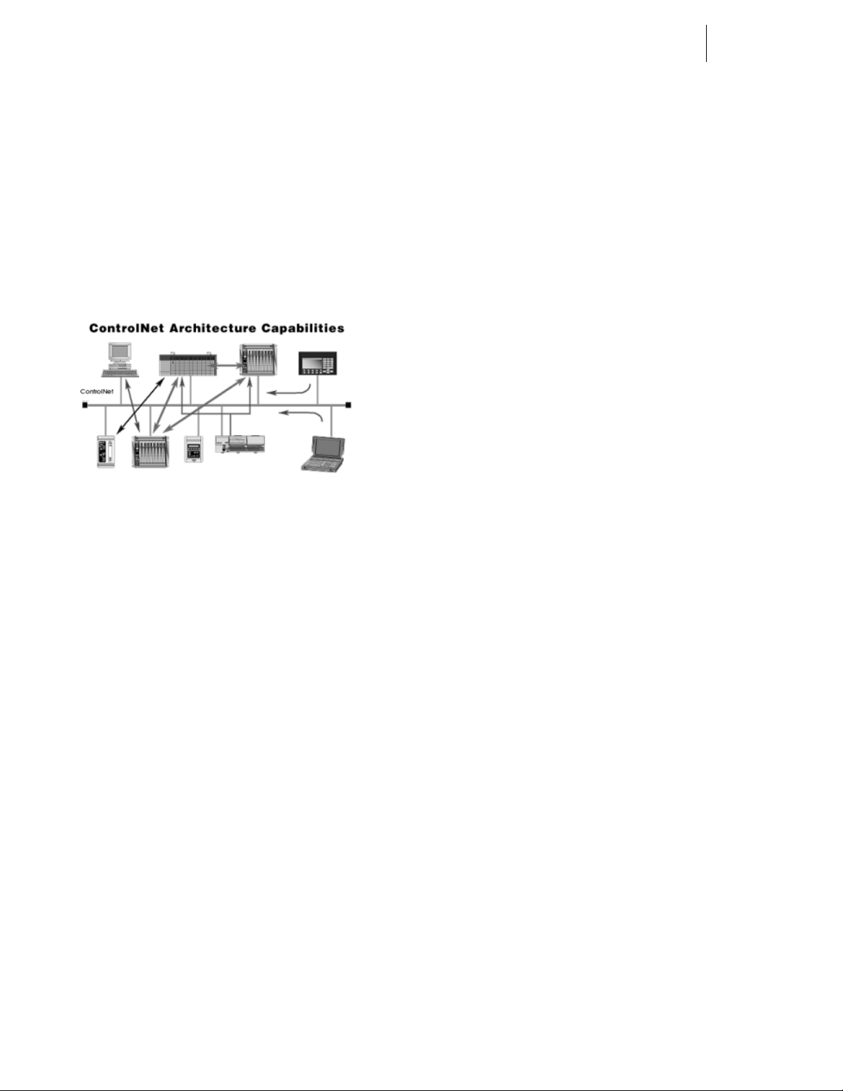
ControlNet
ControlNet enables multiple controllers to control I/O on the
same wire and permits multicast of both inputs and peer-topeer data, reducing traffic on the wire and increasing system
performance. (See Fig. 1)
FIG. 1: CONTROLNET ARCHITECTURE
ControlNet is highly deterministic and repeatable. These are
important requirements to ensure dependable, synchronized
and coordinated real-time performance. Determinism is the
ability to reliably predict when data will be delivered, and
repeatability ensures that transmit times are constant and
unaffected by devices connecting to, or leaving, the network.
These capabilities are further enhanced with user selectable
I/O and controller interlocking update times to match application requirements.
ControlNet meets the requirements of real-time, high speed
applications at the Automation and Control Layer and integrates complex control systems such as batch control systems, weigh process control systems and systems with
multiple controllers and human-machine interfaces.
*.GSD file and setting the Node Address and Input and Output Sizes is all you need to begin communicating weighing
parameters to and from an HI 3000 Series controller to a
PLC, PC or DCS system controller.
MOD-Bus/TPC/IP
TCP/IP is the common transport protocol of the Internet and
is actually a set of layered protocols, providing a reliable
data transport mechanism between machines. Ethernet has
become the de facto standard of corporate enterprise systems
and it has also become the de facto standard for factory networking. Ethernet has matured to the point that the cost of
implementing this network solution has been dropping to
where its cost is commensurate with those of today's fieldbuses. Using Ethernet TCP/IP in the factory allows true integration with the corporate Intranet and MES systems that
support your factory.
Combining a versatile, scaleable, and ubiquitous physical
network (Ethernet) with a universal networking standard
(TCP/IP) and a vendor-neutral data representation (MOD-
®
BUS
) gives a truly open, accessible network for exchange
of process data. It is also extremely simple to implement for
any device that supports TCP/IP sockets.
Simplicity: MODBUS
®
instruction set and wraps TCP/IP around it. If you
BUS
already have a MODBUS
®
TCP/IP simply takes the MOD-
®
driver and if you understand
Ethernet and TCP/IP sockets, you can in short period of
time, have a driver up and running and talking to a PC.
There are no exotic chipsets required to be purchase d from
vendors, and you can use standard PC Ethernet cards to talk
to your implemented device. As the cost of Ethernet falls,
you benefit from the price reduction of the hardware, and as
the performance improves from 10 to 100 Mbit and soon to 1
Gbit, your technology moves with it protecting your investment.
NOTE: Mod-BUS
®
is a registered trademark of Sch-
neider Automated Inc.
Profibus
The Profibus-DP Communication Profile is designed for
efficient data exchange at the field level. The central automation devices, such as PLC/PC or process control systems,
communicate through a fast serial connection with distributed field devices such as I/O, drives and valves, as well as
measuring transducers. Data exchange with the distributed
devices is mainly cyclic. The communication functions
required for this are defined by the basic DP functions in
accordance with the EN 50 170 standard. In addition to these
basic functions, DP also offers extended acyclic communication services for the parameterization, operation, monitoring
and alarm handling of intelligent field devices. Loading the
OPC
OLE for Process Control (OPC) enables an HI 3000 module
to communicate with any device that supports OLE/COM.
The architecture is designed to utilize the Microsoft distributed OLE technology (DCOM) to facilitate clients interfacing to remote servers.
Page 17
3 Communications
Installation & Operation
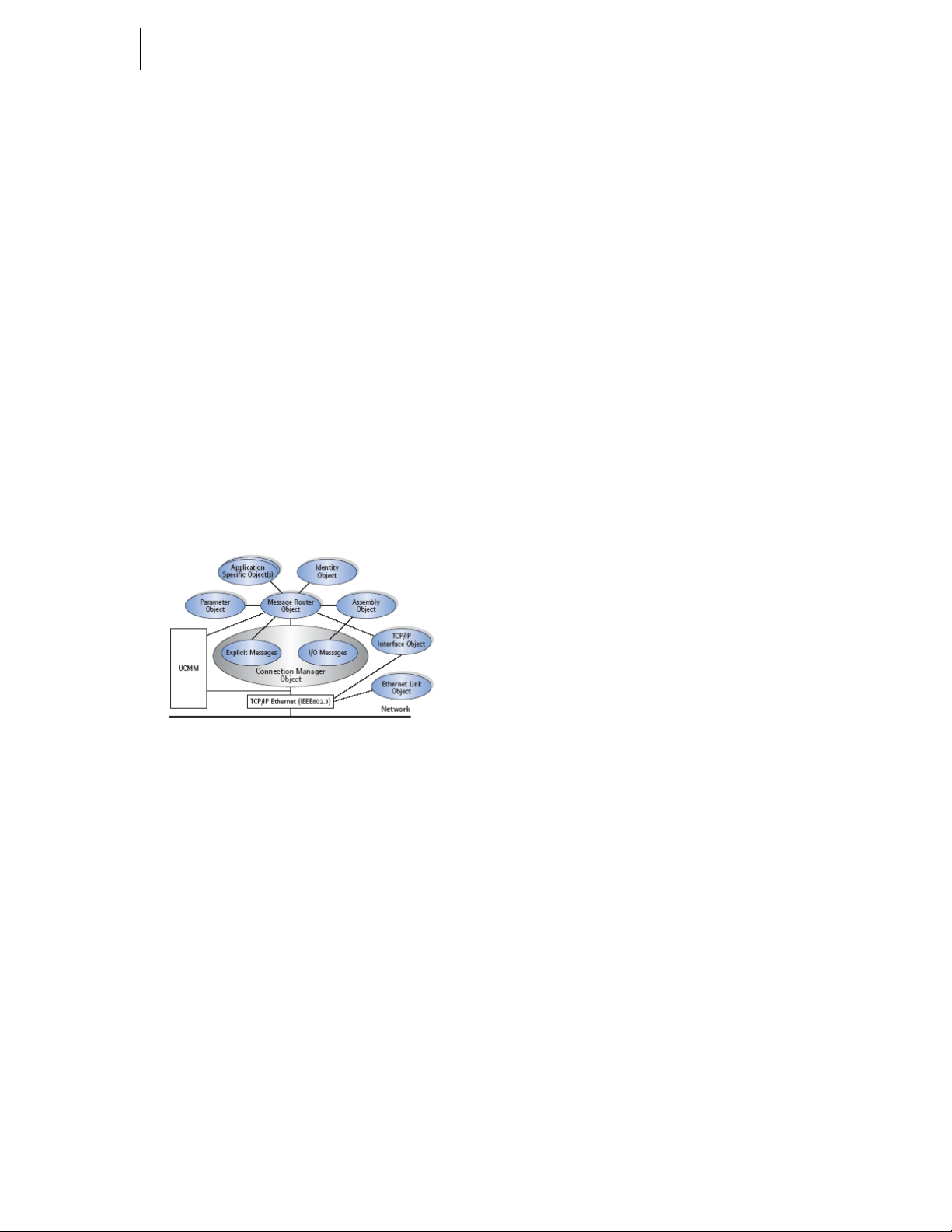
EtherNet/IP™
EtherNet/IP, short for Ethernet Industrial Protocol, is an
open industrial networking standard that takes advantage of
commercial, off-the-shelf Ethernet communication chips and
media. Ethernet technology, enables the user to access
device-level data from the Internet.The Ethernet/IP networking standard supports both implicit messaging (real-time I/O
messaging) and explicit messaging (message exchange).
EtherNet/IP is an open network that takes advantage of commercial technology that already exists.
TCP/IP is the transport and network layer protocol of the
Internet and is commonly linked with all Ethernet installations and the business world. TCP/IP provides a set of services that any two devices can use to share data. Because
Ethernet technology and standard protocol suites such as
TCP/IP have been published for public use, standardized
software tools and physical media have been mass-produced
and are readily available, offering you the benefits of known
technology and accessibility. The UDP/IP (User Datagram
Protocol) is also used in conjunction with the Ethernet network. UDP/IP provides fast, efficient data transport required
for real-time data exchange.
is needed to begin communicating weighing parameters to
and from an HI 3000 Series controller.
Each Hardy HI 3000 Series represents a quarter (1/4) rack of
discrete I/O (32 bits in the PLC Output and Input image
files) to the scanning PLC and supports both discrete and
block transfers. The PLC continually exchanges 32 bits of its
PLC Input Image Table and 32 bits of its Output Image T able
with each 1/4 rack device. In a 1771 I/O Rack, these bits
would normally be transferred from and to discrete input and
output modules. For the weight controller, the Output Image
bits are used to send commands to the weight controller and
the Input Image bits return weight data and scale status bits.
These actions are referred to as “discrete writes and “discrete
reads”. The user is also able to exchange blocks of data with
a 1/4, 1/2, 3/4, Full rack device via Block Transfer instructions in the PLC ladder logic program. These commands are
referred to as “block writes” and “block reads”.
The host programmable controller can access all configuration and weighing parameters in an HI 3000 Series Instrument, including performing scale calibration. The HI 3000
Series module can be used as a local display and keyboard
for weighing parameters, or function as a blind controller
properly digitizing the load cell signal and providing responsive setpoint control.
FIG. 2: ETHERNET/IP™ NETWORK
NOTE: EtherNet/IP™ is a trademark of Rockwell Auto-
mation Inc.
Allen-Bradley Remote I/O
Allen-Bradley License
Under license from The Allen-Bradley Corporation, Hardy
has developed a Remote I/O Interface for the HI 3000 Series
products.
Hardy Process Solutions worked with substantial customer
input and Allen-Bradley to identify and design the remote I/
O communications network which best matched the needs of
system integrators and end users for industrial and process
applications. The interface is fast, field proven, requires minimal wiring, requires no special software drivers, and is standard on many Allen-Bradley programmable controllers.
Setting each address and baud rate in the instrument, connecting three wires, and writing some ladder logic is all that
Using the Remote I/O interface shortens development time
and provides the most functional weighing interface available for your Allen-Bradley programmable controller.
Before starting system design, you should also read the
Installation and Operation manual of the HI 3000 Series.
Information contained in this manual is subject to change.
Always check the latest version of this manual at our web
site (http://www.hardysolutions.com) before beginning system design. This product incorporates technology which is
licensed by Allen-Bradley Company Inc. Allen-Bradley
does not technically approve, warrant or support this product. All warranty and support for this product is provided by
Hardy. PLC
®
, PLC-2®, PLC-3®, PLC-5®, SLC500® Series
are registered trademarks of the Allen-Bradley Company,
Inc.
Common Applications
The HI 3000 Remote I/O can be used in conjunction with
Allen-Bradley programmable controllers to tackle a variety
of process control needs. The most basic use of the interface
is to simply allow the programmable controller to read
weight data from one or more HI 3000 Series weight controllers. In addition to reading weight some other applications
are:
• Filling
• Dispensing
• Batch Weighing Control
• Monitoring Rate of Flow
Page 18
HI-3000 Series 4
Operation and Installation
• Evaluating Totalized Weight
• Check Weighing
• Weight Level Alarming
• Condition Monitoring
NOTE: The 3000 Series have 4 mappable outputs in the
HI 3010 FillerDispenser and HI 3030 Multiscale controller and up to seven (7) on some of
the other 3000 Series products.
Monitoring Weighing Parameters
The HI 3000 series weight controllers are capable of calculating five types of weight data, including the standard Gross
and Net weights. In addition to the standard Gross and Net
weights there are three options such as Peak Force, Totalized
Weight (block transfer only), and Rate-of-Change or mass
flow rate entering or leaving a vessel.
Short Glossary of Terms
1. Gross Weight - is used to describe the total weight
of the container and the contents.
2. Net Weight - is the weight of the contents of the
container only.
3. Tare Value - The action of adjusting out the known
weight of the container from the total indicated
weight, so that the indicator reads weight directly.
4. Dead Load - The weight of the vessel and other
equipment which will be ignored during zero calibration.
are connected one to another in a series. The first and last
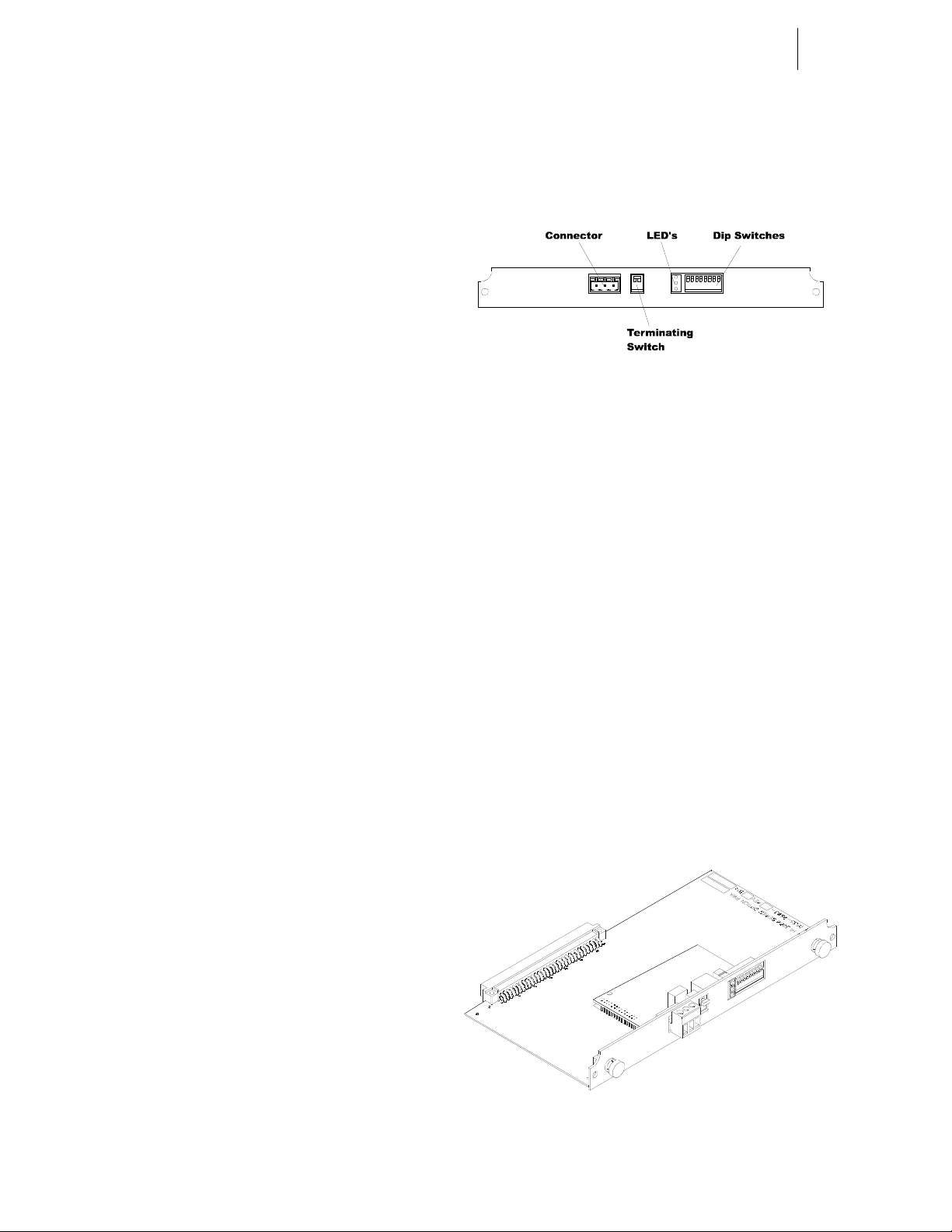
Remote I/O module must be terminated.
Step 1. The Terminating Switch is accessible from the rear
of the HI 3000 Series Module. (See Fig. 3)
FIG. 3: TERMINATING SWITCH FOR
TERMINATING LAST MODULE
Step 2. On the first module and the last module turn the ter-
minating switch to ON.
Step 3. For all other devices on the daisy chain the termi-
nating must be set to OFF.
Dip Switch Settings
Set all the Dip Switch Settings to ON. (See Fig. 3)
Installing the RIO Option Board
CAUTION: M
STRAP WHEN INSTALLING THE REMOTE I/O OPTION
C
ARD.
AKE SURE THAT YOU USE AN ANTI-STATIC
Tare Value
Current Gross Weights become the Tare value by pushing
the Tare Push Button on the front panel of the HI 3000
instrument, remote functions contact closure, discrete write
or block transfer command by the PLC, or can be entered as
a numeric value via the keypad on the front panel of the HI
3000 Series instruments This new tare value is the reference
point for Net Weight.
TV = G - N
TV = Tare Value (weight)
G = Gross Weight
N = Net Weight
Remote I/O Board Cable Termination Dip Switch Configuration
About Cable Termination
HI 3000 Series Remote I/O Modules are connected to a cable
in daisy-chain fashion and are referred to as “nodes”. A
Daisy Chain is a hardware configuration in which devices
Step 1. Position the RIO Option Card with the back plane
connector facing Option Slot #0. (See Fig. 4)
NOTE: You can only use Option Slot #0 when installing
the RIO Option Card.
FIG. 4: REMOTE I/O OPTION CARD
Step 2. Slide the RIO Option Card into Slot #0. (See Fig. 5)
Page 19
5 Communications
Installation & Operation
Connector Pin Out
Option Slot 1
Option Slot 0
FIG. 5: REMOTE I/O/SLIDE INTO OPTION SLOT #0
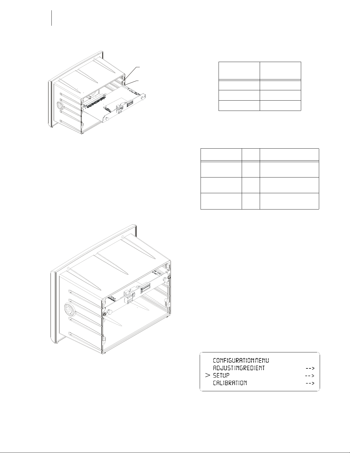
Step 3. Push the Remote I/O card up against the back plane
and gently press until the card connector seats in the
back plane connector.
Step 4. Use a phillips head screw driver and install the two
(2) screws that fasten the RIO card panel to the HI
3000 Instrument Chassis. (See Fig. 6)
Step 5. Tighten the screws until the RIO panel is snug. Do
not overtighten.
Screw Terminal
(3-pin)
1Blue
2Shield
3 Clear
Description
TABLE 1: SCREW TERMINAL (3-PIN) PIN OUT
LED Indicators
LED Color Function
Error
(Top LED)
Power
(Bottom LED)
Active
(Middle LED)
Red Off: Normal Operation
On: Bus off/error
Green Off: Power is Off
On: Power is On
Green Off: No Communication
On: Communication Active
TABLE 2: LED INDICATORS
Removing the Remote I/O Option Card
FIG. 6: REMOTE I/O OPTION CARD INSTALLED
Step 6. Connect the Remote I/O cable to the 3 pin connec-
tor on the RIO board.
Step 7. Connect the other end of the Remote I/O cable to
the PLC, SLC or PC Remote I/O Interface card.
Step 1. Disconnect the cables.
Step 2. Use a phillips head screw driver and remove the
two (2) screws that fasten the RIO Option Card
panel to the HI 3000 Chassis.
Step 3. Using the thumb and index finger on both hands,
grasp the two (2) knobs on the RIO Card panel and
pull away from the instrument.
Step 4. When the RIO Option Card clears the chassis, store
in a static free, safe location.
Remote I/O Configuration Procedures from the Front Panel
Step 1. At the front panel click on the Setup/3 button. The
Configuration Menu appears. (See Fig. 7)
FIG. 7: CONFIGURATION MENU/SELECTING
SETUP
Page 20
HI-3000 Series 6
>
Re mot e I/ O ON ->
Cont r ol N et I/ O OFF
Operation and Installation
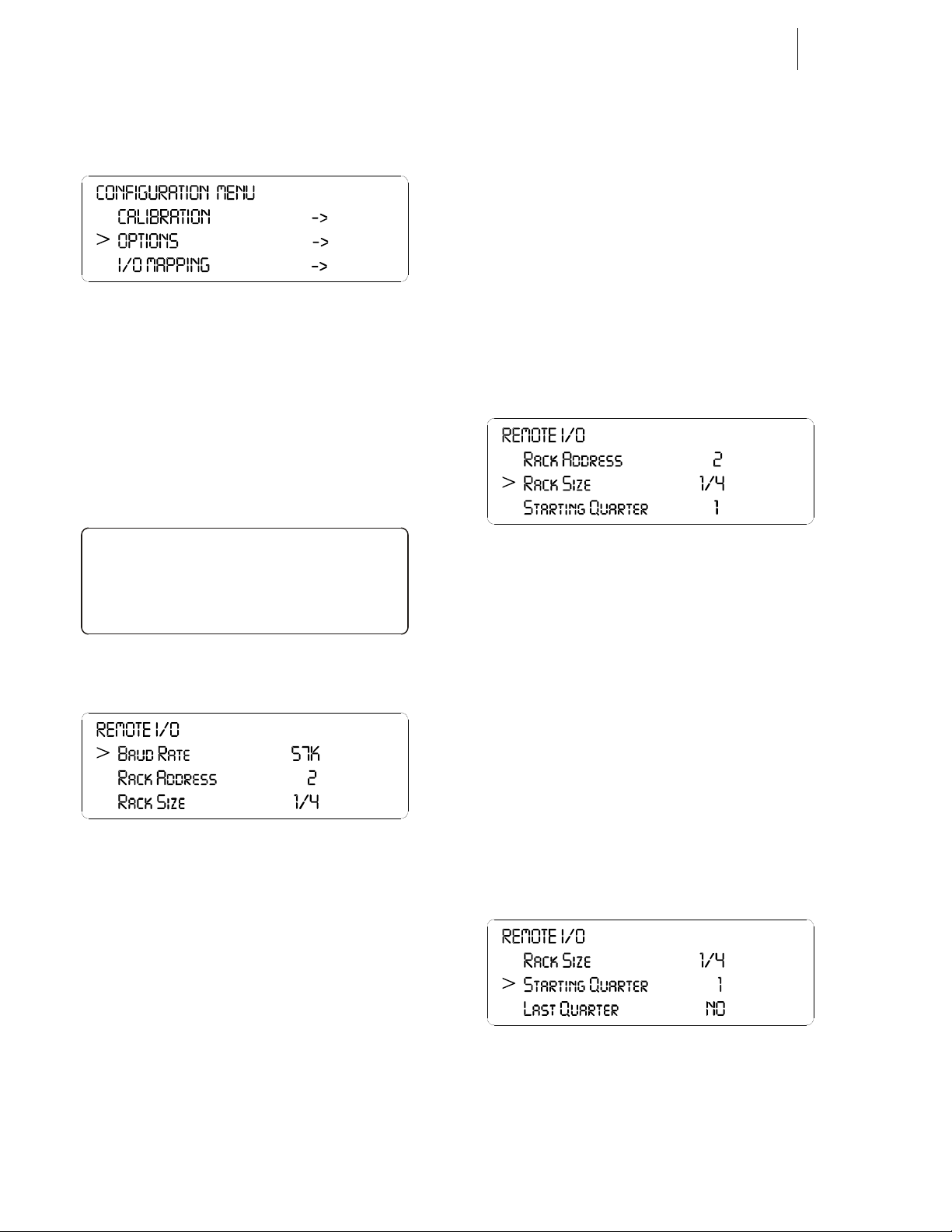
Step 2. Push the up or down arrows until the cursor is next
to “OPTIONS”. (See Fig. 8)
FIG. 8: CONFIGURATION MENU/SELECTING
OPTIONS
Step 3. Press the Enter button. The Options submenu
appears with Remote I/O selected. (See Fig. 9)
Step 4. If the cursor is not in front of Remote I/O, push the
up arrow until the cursor is aligned with Remote I/
O.
Step 5. Press the Enter button. The Remote I/O Menu
appears. (See Fig. 10)
OPTIONS
• You can set the rack address in one of two
ways.
1. Press on the clear button to clear the
existing value then use the alphanumeric keys to enter the address for this
module.
2. Press on the right or left arrow buttons
to select the address.
• Address Range - 0-59
Step 9. Press the Enter button to save the setting.
Step 10. Press the down arrow button until the cursor is in
front of Rack Size. (See Fig. 11)
FIG. 11: REMOTE I/O/SETTING RACK SIZE
FIG. 9: OPTIONS/SELECTING REMOTE I/O
FIG. 10: REMOTE I/O MENU/SETTING
PARAMETERS
Step 6. Press the right or left arrow buttons to select the
Baud Rate. Left arrow decreases the rate and the
right arrow increases the rate. Baud Rate Selections
are:
• 57 kbaud
• 115 kbaud
• 230 kbaud.
Step 7. Press the Enter button to save the setting.
Step 8. Press the down arrow button until the cursor is in
front of Rack Address.
Step 11. Press the right arrow button to select the rack size
of this module. The choices are:
• 1/4 quarter (Can start at 1,2,3,4)*
• 1/2 half (Can start at 1,2,3)*
• 3/4 three quarter (Can start at 1,2)*
• FULL (Can start at 1)*
NOTE: *The starting points are important when making
the starting quarter selection. For example you
can have a 1/4 rack start at quarter 1 and a 1/2
rack start at quarter 2.
Step 12. Press the Enter button to save the setting.
Step 13. Press the down arrow button until the cursor is in
front of Starting Quarter. (See Fig. 12)
FIG. 12: REMOTE I/O SELECTING STARTING
QUARTER
Step 14. Press the right or left arrow buttons to select the
starting quarter for this module. Keep in mind the
starting quarter requirements due to rack size.
Page 21
7 Communications
Installation & Operation
Step 15. Press the Enter button to save the setting.
Step 16. Press the down arrow button until the cursor is in
front of Last Quarter.
Step 17. Press the right or left arrow buttons to toggle
between NO and YES. If the module is in the last
quarter select YES. If the module is not in the last
quarter select NO. Make sure you make the correct
selection each time.
Remote I/O Configuration Procedures from the Web Page
Step 1. From the Home Page of the Instrument Click on
Configuration. (See Fig. 13) The Configuration
Options page appears. (See Fig. 14)
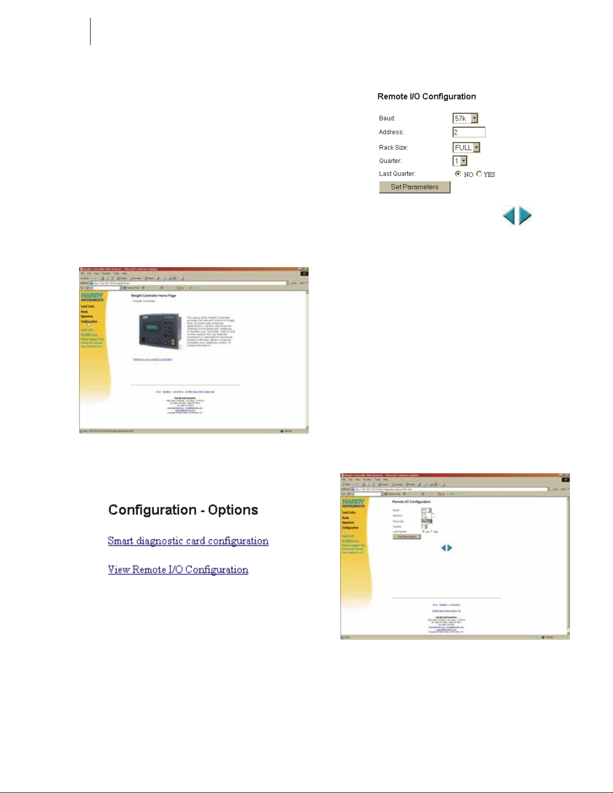
FIG. 15: REMOTE I/O CONFIGURATION PAGE
Step 3. To select the Baud rate click on the Baud: pull
down menu. (See Fig. 16)
Step 4. Click on the Baud Rate you want to select. Baud
Rate Selections are:
FIG. 13: INSTRUMENT HOME PAGE/SELECTING
CONFIGURATION
FIG. 14: CONFIGURATION - OPTIONS PAGE/
SELECTING VIEW REMOTE I/O CONFIGURATION
• 57 kbaud
• 115 kbaud
• 230 kbaud.
NOTE: If you only select one parameter (e.g. Address)
you need to click on set configuration to set the
entry. You do not need to select every category
before setting the configuration.
Step 2. Click on View Remote I/O Configuration. (See Fig.
14) The Remote I/O Configuration page appears.
(See Fig. 15)
FIG. 16: REMOTE I/O CONFIGURATION/
SELECTING BAUD RATE
Step 5. To set the Node Address double Click in the
Address Field. Type in the Node Address of this
module.
• Address Range - 0-59
Page 22
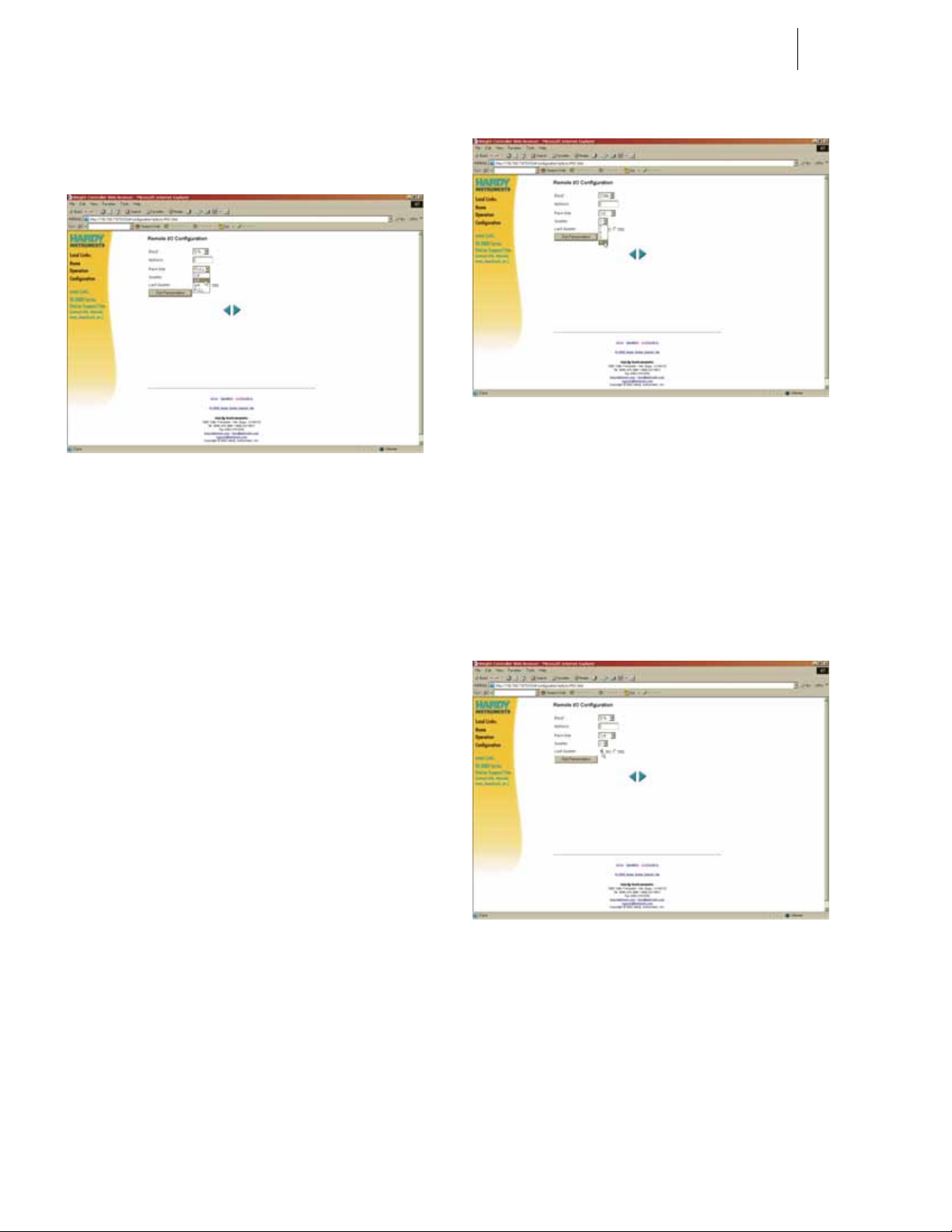
Step 6. To Select the Rack Size, click on the Rack Size pull
down menu. (See Fig. 17)
HI-3000 Series 8
Operation and Installation
FIG. 18: REMOTE I/0 CONFIGURATION/
SELECTING QUARTER
FIG. 17: REMOTE I/O CONFIGURATION/
SELECTING RACK SIZE
Step 7. Click on the Rack Size of this module.
The choices are:
• 1/4 quarter (Can start at 1,2,3,4)*
• 1/2 half (Can start at 1,2,3)*
• 3/4 three quarter (Can start at 1,2)*
• FULL (Can start at 1)*
NOTE: *The starting points are important when making
the starting quarter selection. For example you
can have a 1/4 rack start at quarter 1 and a 1/2
rack start at quarter 2.
Step 8. To select the Quarter Location, click on the Quarter
pull down menu. (See Fig. 18)
Step 9. Click on the Quarter location number of this instru-
ment.
Step 10. You need to determine if this instrument is in the
last quarter. If this instrument is not the Last Quarter click in the radio button next to NO (NO is the
default selection). If this instrument is the Last
Quarter click in the radio button next to YES. (See
Fig. 19)
FIG. 19: REMOTE I/O CONFIGURATION/
SELECTING LAST QUARTER
Step 11. Click on the Set Parameters button to set the config-
uration.
Page 23

9 Communications
Installation & Operation
Discrete Remote I/O Mapping
NOTE: The input and output tables on the HI 3010
device always start with word 0, regardless of
where the words end up in the PLC tables. In the
HI 3030 Byte 0 of Word 0 is reserved and cannot
be used.
About Discrete Remote I/O Mapping
Discrete Remote I/O Mapping is used when you want to
communicate from a 1/4 or 1/2 rack, due to the constraints
when getting information in and out of these units.
General Information
• bit: FEDCBA98 76543210
• W0: SWYYYYYY 00000000
S - command-type: 0 = normal 1 = short
W - R/W action: 0 = read 1 = write
Y - depends on W
For Reads:
W0: 10AX XNNN 0000 0000 command word (LSB unused)
W1: - - - - - - - - QQQR RRRR data word (MSB unused)
1. RSO45=HFI3 (This maps the Net Weight in lbs
into a short int at word 13, RO)
2. CMD0=RSI0 (This indicates there is a command in
the RIO in-table word 0.)
PLC puts into the Output file (assuming HI3000 is at 1
st
¼
rack 2):
SWA
0:020: 10000001 00000000
QQQRRRRR
0:021: 000000 00101101
S = 1 A short command
W = 0 A read
A = 0 No ACK
NNN = 1 Read one word
RRRRR = 13 Word Offset 13+32, (i.e. RO45)
QQQ = 1 Copy to RO1 . . .
This copies one word from word 45 of the RIO out-table to
word 1 of the RIO out-table. The data becomes available for
RIO discrete PLC reads. Anything that can be mapped can
be selected by the command, including remote data. Largerrack users can specify up to 7 words to read into the discrete
I/O area.
For Writes:
A If A=1, unit acknowledges by copying data
byte to bits RO0.8~RO0.15
XX Reserved. Set to zero.
NNN Number of words to copy out (0 thru 7)
RRRRR Index in output scratchpad table of first source
word to copy. Scratchpad starts at word 32 of
Output Table. Data will be copied, without
conversion, to word QQQ and subsequent
words
QQQ Destination word in Output table of first copied
word (note that RO1 is first usable full RIO
word)
NOTE: If command comes from RI, output will be in RO.
If input is DI, output will be in DO.
Read Example: For HI 3010
Read Net Weight into word RSO1 as 16 bit integer in 1/4
rack at address 2, first quarter:
In Mapping write the following:
W0: 11MNNNNN 00000000 Command Word (LSB
unused)
JJJJJJJJ JJJJJJJJ
W1:
J J J J J J J J J J J J J J J J J J) Second (optional) data word
(W2:
M Data Length
0 = 1 word
1 = 2 words (not usable for 1/4 rack)
NNNNN Index in input scratchpad table of word to
change. One or two data words will be
copied without conversion. Scratchpad
table begins at word 32 of Input Table.
First Data Word
NOTE: There is no command echo for writes.
Write Example 1: For HI 3030
Write 1042 to ingredient 1 Number of Fills:
In Mapping:
Page 24

HI-3000 Series 10
Operation and Installation
User sets: HSO5=RS141 Meaning - Number of Fills
= RIO Short Input word 41.
User Writes:CMD0=RSI0 Meaning - There is a com-
mand at RIO in-table word 0.
PLC puts into its Output file (assuming HI3000 is at 1
rack 2):
SWMNNNNN
O:020: 11001001 00000000
J J J J J J J J J J J J J J J J J J
0:021: 00000100 00010010
S = 1 A short command
W = 1 A Write
M = 0 Write 1 word
NNNNN=1001)
Word Offset = 9 (32+9=41)
2
JJJJJJJJ JJJJJJJJ Value to write 2
Write Example 2: For HI 3010
Write 597.1 to ingredient 1 target weight:
In Mapping:
User sets: HFO9=RFI45 Meaning - ingr1 target wt =
RIO Float Input word 45.
User Writes:CMD0=RSI0 Meaning - There is a com-
mand at RSIO in-table word 0.
PLC puts into its Output file (assuming HI3000 is at 1
rack 2) and 1/2 rack sizes:
SWMNNNNN
0:020: 11101101 00000000
J J J J J J J J J J J J J J J J J J
0:021: 01000100 00010101
J J J J J J J J J J J J J J J J J J
0:022: 01000110 01100110
S = 1 A short command
W = 1 A Write
M = 1 Write 2 word
NNNNN=(1101)
Word Offset - 13(32+13=45)
2
Mapping
Mapping is used to:
1. Configure local inputs and outputs of the 3000 Con-
st
¼
NOTE: The 3000 Controllers are Masters on DeviceNet,
Any number of Sources can be mapped to one Destination
using the Boolean Statements in the Advanced Mapping
Screen.
Step 1. Select One Destination from the pull down lists in
Step 2. Select one Source in the same manner as in step a.
st
¼
Step 3. If more than one source is desired, select one of the
Step 4. To initiate the displayed mapping equation, select
Step 5. To Unmap - or remove a mapping equation - only
Step 6. For more information about Mapping go to the
troller using Boolean or non-Boolean statements.
2. Map parameters between Controllers using an
Ethernet Network.
3. Map parameters, setpoints, or commands between
the local controller and any of the supported communication networks, including ControlNet, AllenBradley Remote I/O and DeviceNet.
meaning any parameter can be assigned
(mapped) to 3rd party I/O on the DeviceNet Network. The Rockwell Automation software package "RSNetworx" is used to assign the I/O on the
plant network. HI 3000 Controllers can also be
Slave Devices.
the Local, Network, or Control fields. Once
selected, the Destination will automatically fill in
on the left-hand side of the equation in the mapping
field.
The source can reside in the local controller as a
parameter, as a point on one of the network tables,
or as a parameter on another 3000 Controller on the
Ethernet network. Once selected, the source will
automatically fill in on the right-side of the equation in the mapping field.
Boolean Operators (And, Or, Not), and then repeat
step b to select the next source.
the 'Map' key.
the destination needs to be selected and the Unmap
key pressed.
Mapping Chapter for each individual HI 3000
Series product.
J . . = 01000100 00010101
Value to write 0x4415 = MSW of IEEE float
597.1
j . . = 01000110 01100110
Value to write 0x4666 = LSW of IEEE float
597.1
Page 25
11 Cabling
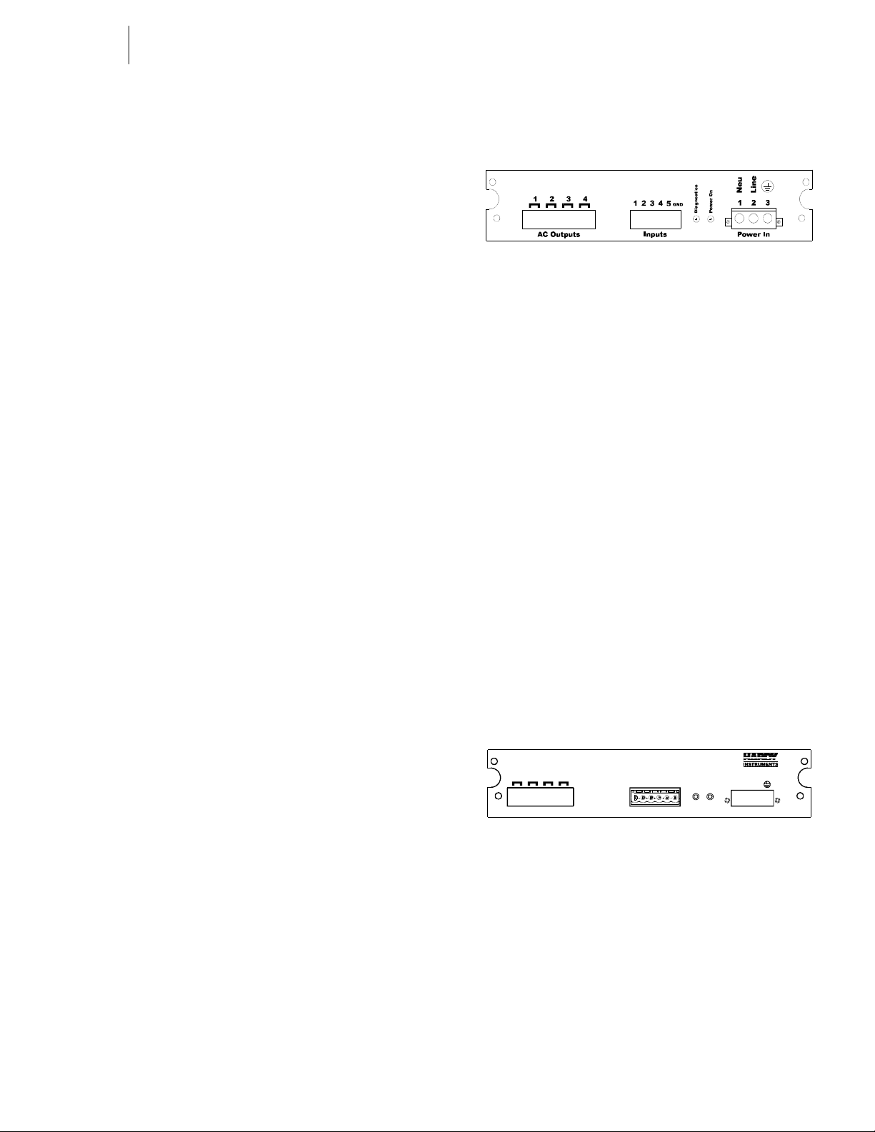
Power In
Power On
Diagnostics
Inputs
Gnd
1234
5
Neu
Line
www.hardyinst.com/3000
2341
Outputs
Installation
CABLING: INSTALLATION
General Introduction to Cabling
This section pertains to unpacking the instrument and installation of the Power, Load Cells, DeviceNet and Ethernet
Cables. For more detailed installation information please
refer to the HI 3000 Series Service Manual. For specification
information please read the HI 3000 Series Service Manual.
It is highly recommended that the user follow the installation
instructions either implied or explicitly stated in this section
to insure the instrument operates as designed.
Unpacking
Step 1. Before signing the packing slip, inspect the packing
for damage of any kind.
Step 2. Report any damage to the carrier company immedi-
ately.
Step 3. Check to see that everything in the package
matches the bill of lading.
Step 4. If any items are missing, damaged, or you have any
questions, please contact Technical Support at:
Hardy Process Solutions.
9440 Carroll park Drive
San Diego, CA 92121
Phone: (858) 278-4900
FAX: (858) 278-6700
Web Site: http://www.hardysolutions.com
E-Mail: hardysupport@hardysolutions.com
Step 5. Record the model number and serial number of the
Filler/Dispenser Controller. Store in a convenient,
secure location for reference when contacting
Hardy Technical Support Department or to buy
parts or firmware upgrades.
FIG. 20: POWER WIRING DIAGRAM
• Power Input J1
J1-1 Neu (Low)
J1-2 Line (HI)
J1-3 Ground
Step 1. The HI 3000 Series instruments are configured with
a universal power supply rated from 120 to 240
VAC. The instruments can be powered by a 120 or
240 VAC power source and requires no switching
or jumper settings.
Step 2. Install a 3-wire, minimum 14 AWG power line to
the 3-pin terminal block connector. (See Fig. 20)
Step 3. The power and relay circuit card filters and condi-
tions AC power. However, for noisy power lines,
external conditioning may be required. For more
information, consult the HI 3000 Series Installation
and Service Manual or contact Hardy Instruments
Technical Support.
Digital Input Wiring
The 5 digital inputs to the HI 3000 series instruments are
mappable inputs and are only active when connected to
ground. (See Fig. 21)
Input Power Wiring
WARNING: DO NOT OPERATE WITH INCORRECT LINE
VOLTAGE. TO DO SO WILL RESULT IN PROPERTY DAMAGE
AND/OR PERSONAL INJURY. MAKE SURE THAT THE POWER
SOURCE DOES NOT EXCEED 240 VAC.
• The AC power should be supplied by a “clean” primary
line, directly from the power panel. This line should not
supply any other equipment, including the feeding unit,
and should be supplied with a minimum 10 amp breaker.
(See Fig. 20)
FIG. 21: POWER SUPPLY BOARD REAR PANEL
WARNING: N
DRIVER. DO NOT WIRE 110 VOLTS INTO THE DIGITAL
INPUTS. TO DO SO WILL CAUSE PROPERTY DAMAGE AND/
OR PERSONAL INJURY.
O V OLTAGE EXCEPTED AS AN INPUT
Step 1. Connect the input wire to the selected input.
Step 2. Connect the input wire to some form of dry contact
switch. (See Fig. 22)
Page 26
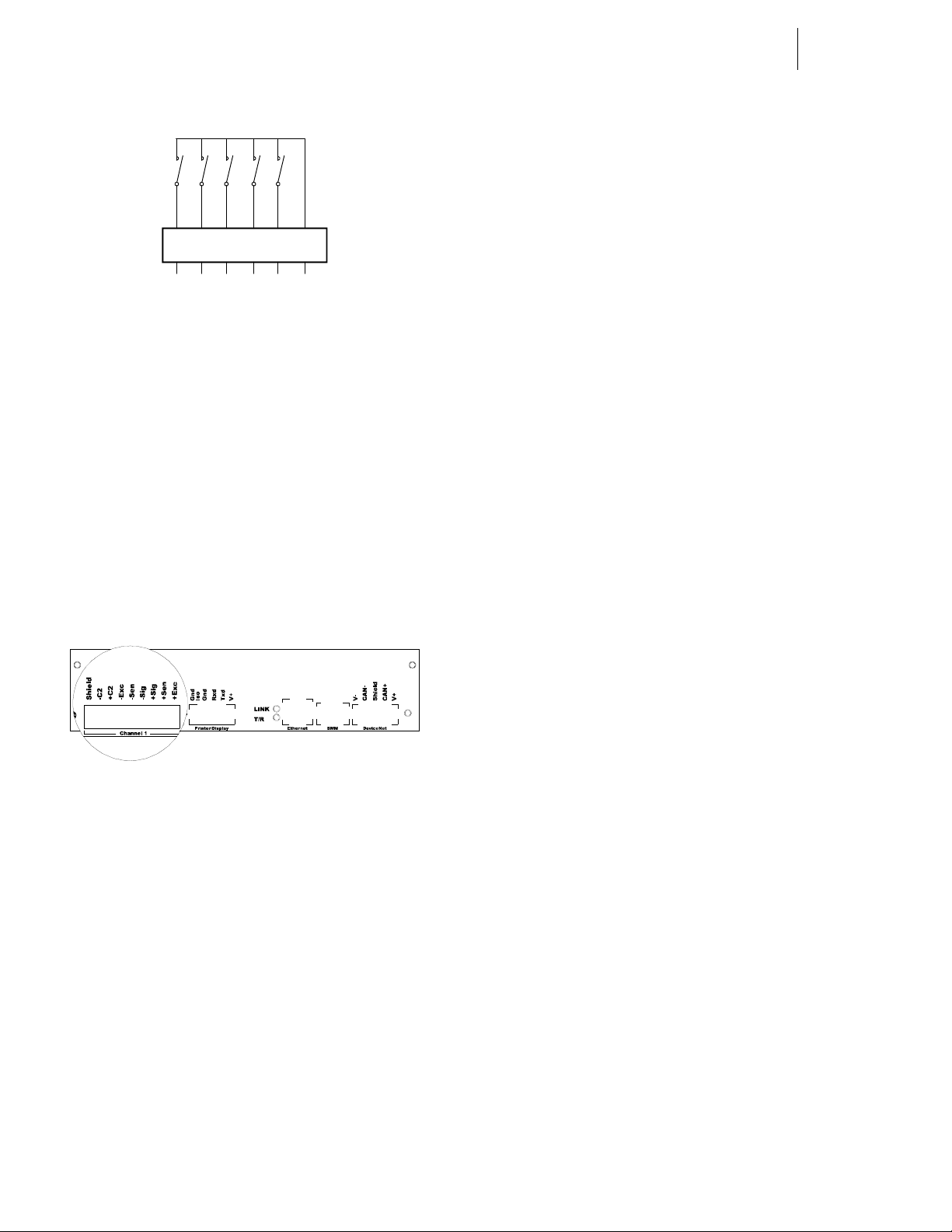
Gnd12345
FIG. 22: DRY CONTACT WIRING DIAGRAM
Step 3. Go to the product service manuals (Chapter 6) for
instructions on how to map to the digital inputs.
Output Relay Wiring
The HI 3000 Series has 4, OPTO22 solid state relays. Please
see Relays in Chapter 2 - Specifications of each product Service manual for details.
Step 1. Wire into the output relay of your choice.
Step 2. Go to the product service manuals (Chapter 6) for
instructions on how to map to the output relays.
HI-3000 Series 12
Operation and Installation
• SIG+ Green
•SEN+ BLUE
•EXC+ RED
Step 1. Remove the factory installed jumper from the ter-
minal block if you are connecting an 8 wire cable
from the junction box.
Step 2. Connect the cable (Recommended load cell cable:
Hardy Instruments Prt. # 6020-0001) wires to the
Channel 1 terminal block according to the cable
color chart.
NOTE: T o purchase Hardy Load Cell cable, contact your
local Hardy Representative or Distributor.
Step 3. Plug the terminal block into the Channel connector
on the rear panel.
Step 4. For more information concerning C2 Load Point
connections, consult the individual HI 3000 Series
Product, Installation and Service Manual.
Non-C2 Load Cell Connection
Cable color Code using Hardy cable from a junction to an
instrument - for Non-C2 load cells:
Load Point Connections
FIG. 23: REAR PANEL/LOAD POINT CONNEC-
TIONS
®
C2
Load Point Connection
WARNING: L
CULATED INTO C2 CALIBRATION DATA. HARDY PROCESS
S
OLUTIONS RECOMMENDS THAT YOU DO NOT CUT YOUR
A
DVANTAGE OR ADVANTAGE LITE LOAD SENSOR CABLE,
AS YOUR C2 ACCURACY WILL BE AFFECTED AND THE
WARRANTY WILL BE VOIDED.
Cable color Code for C2 Load Points (left to right facing the
rear panel):
OAD CELL CABLE LENGTH HAS BEEN CAL-
• Shield Ground Wire
•C2- Violet
•C2+ Grey
• EXC- Black
•SEN- Brown
•SIG- White
• Shield Ground Wire
• C2- Not Used
• C2+ Not Used
• EXC- Black
•SEN- Brown
• SIG- White
• SIG+ Green
•SEN+ Blue
•EXC+ Red
Step 1. Remove the factory installed jumper from the ter-
minal block if you have 6 wire load cell cable that
includes sense wires from the load cell or junction
box.
Step 2. Connect the cable (Recommended load cell cable:
Hardy Prt. # 6020-0001) wires to the J9 terminal
block according to the Non-C2 cable color chart.
Step 3. Plug the terminal block into the Channel 1 (J9) con-
nector on the rear panel.
Step 4. For more information concerning Non-C2 Load
Point connections, consult the HI 3000 Series
Installation and Service Manual.
RS 232 Connection
The RS 232 Connection provides for a serial port for transmission to a Printer or a Scoreboard. T o configure the Printer
or Scoreboard see Chapter 4/Serial Port Parameters in the HI
3030 Service Manual.
Page 27
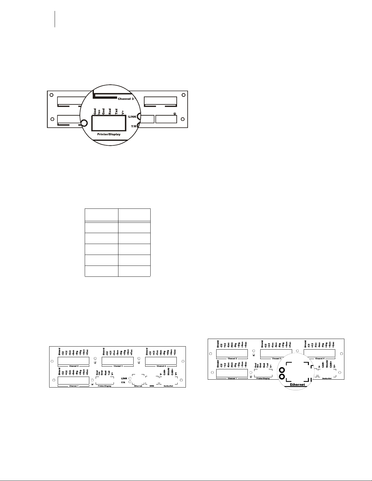
13 Cabling
Channel 2 Channel 3 Channel 4
Channel 1
Prin ter/ Disp lay Ether net SM M D evice net
Neu
Line
LINK
Installation
NOTE: The HI 3000 instrument transmits data only over
a serial connection, it does not receive data.
RS 232 Connection Pinout
Shield
-C2
+C2
-Exc
-Sen
-Sig
+Sig
+Sen-
+Exc
Shield
-C2
+C2
-Exc
-Sen
-Sig
+Sig
+Sen-
+Exc
Shield
-C2
+C2
-Exc
-Sen
-Sig
+Sig
+Sen-
+Exc
Shield
-C2
+C2
-Exc
-Sen
-Sig
+Sig
+Sen-
+Exc
Gnd
Iso
Gnd
Rxd
Txd
V+
T/R
FIG. 24: SERIAL PORT CONNECTION
Reading left to right when viewing the rear panel from the
back.
Pin Number Connection
1Iso Grnd
2Grnd
3Rxd
4Txd
5V+ (5VDC)
Table 3: Serial Port Pinout
Hardware Requirements:
Serial Cable with nine pin connector.
-JB Option Wiring
cell is connected to Channel 1, Channel 2, Channel
3, Channel 4 for future reference.
NOTE: If you have one load point you must plug it into
Channel 1. If you have more than one load point
you must make sure that you plug one of the load
points into Channel 1.
Step 7. If you only have 3 load cells, do not use Channel 4.
Step 8. For more information concerning Non-C2 Load
Cell connections, consult the HI 3000 Series Service Manual.
Ethernet Cable Connection and Setup
Hardware Requirements:
Ethernet Card - 10/100 Base T
Ethernet Cable w/RJ 45 connector.
Step 1. Plug the RJ45 connector into the Ethernet Connec-
tion at the rear panel of the instrument or the Junction Box. (See Fig. 26)
• Plugging the RJ45 connector into an instrument with an HI 3000-RC environmental rear
cap does not require removal of the cover. Use
needle nose pliers to hold the back of the connector. While holding the connector with the
pliers, pass the connector through the access
port and press the connector into the RJ45 connector at the rear of the instrument.
• When removing the connector you will need to
use a small screw driver and needle nose pliers.
While holding the back of the RJ45 connector
with the pliers, use the screw driver to push
down on the latch at the top of the connector.
This releases the connector. Pass the conne ctor
back through the access port.
FIG. 25: -JB OPTION CONNECTIONS
Step 5. Connect the load cell cable wires to the terminal
blocks in accordance with the Load Cell manufacturers color code.
Step 6. Plug the terminal blocks into Channels 1 thru 4 con-
nectors on the rear panel. Write down which load
FIG. 26: REAR PANEL/ETHERNET RJ 45
CONNECTION
Step 2. At the front panel push the Setup button. The Con-
figuration Menu appears. (See Fig. 27)
Page 28
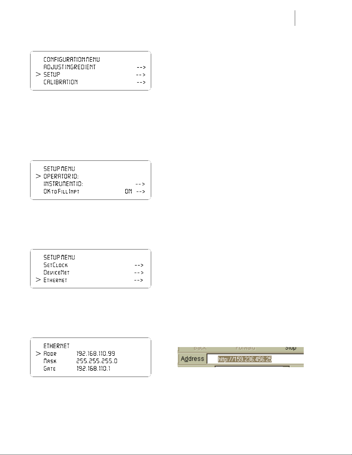
HI-3000 Series 14
Operation and Installation
• Do not repeat any IP addresses used on your
network.
• Make sure that you enter integers before the
periods between values. Do not leave any
periods out of the address.
Bad address: 153.956.124
Correct address: “159.236.456.25”.
FIG. 27: CONFIGURATION MENU/SELECTION
SETUP
Step 3. Push the up or down arrows until the cursor is next
to “SETUP”. (See Fig. 27)
Step 4. Press the Enter button. The Setup Submenu
appears. (See Fig. 28)
FIG. 28: SETUP MENU
Step 5. Press the up arrow until the cursor appears in front
of Ethernet. (See Fig. 29)
FIG. 29: SETUP MENU/ETHERNET SUB-MENU
Step 6. Press the Enter button. The Ethernet sub-menu
appears. (See Fig. 30)
NOTE: Check with your network administrator to get the
correct IP address for your instrument. IP
addresses used in this manual except for the
default IP address are for illustration purposes
only.
Step 8. Use the up or down arrows and move the cursor in
front of “Addr”. Press the clear button to clear the
current or default entry. Use the keypad and enter
the new IP address. Be sure and put the periods
between the entered values of the address.
Step 9. When you have entered the IP Address, press the
Enter button to set the IP Address in the instrument.
Step 10. DO NOT CHANGE THE MASK OR GATE VAL-
UES AT THIS TIME. For information about configuring the Mask, Gate and DNS, please check
with your network administrator or check with
Technical Support at Hardy Instruments Inc.
Step 11. Press the Exit button until you get to the Standby
display.
Step 12. Recycle power to make the IP Address change take
effect.
Step 13. Now that the instrument has a unique IP address
you can connect to it from your browser.
Step 14. Make sure that the ethernet cable is connected to
the HI 3000 Series Instrument and to the ethernet
card in your computer.
Step 15. Type in the Instruments IP address in the Address
field of your browser. For example: “http://
159.236.456.25”. (See Fig. 63) Do not enter the
quotation marks. Once the IP address is entered
press Enter on your computer keyboard. The System Web page appears and you are ready to use the
instrument via the Ethernet. (See Fig. 31)
FIG. 30: ETHERNET MENU/DEFAULT IP ADDRESS
Step 7. The IP address shown in Figure 8 is the default IP
address set at the factory. DO NOT USE THIS
ADDRESS. You must enter a new address. You
must do the following:
FIG. 31: ENTER IP ADDRESS IN BROWSER
ADDRESS FIELD
Page 29
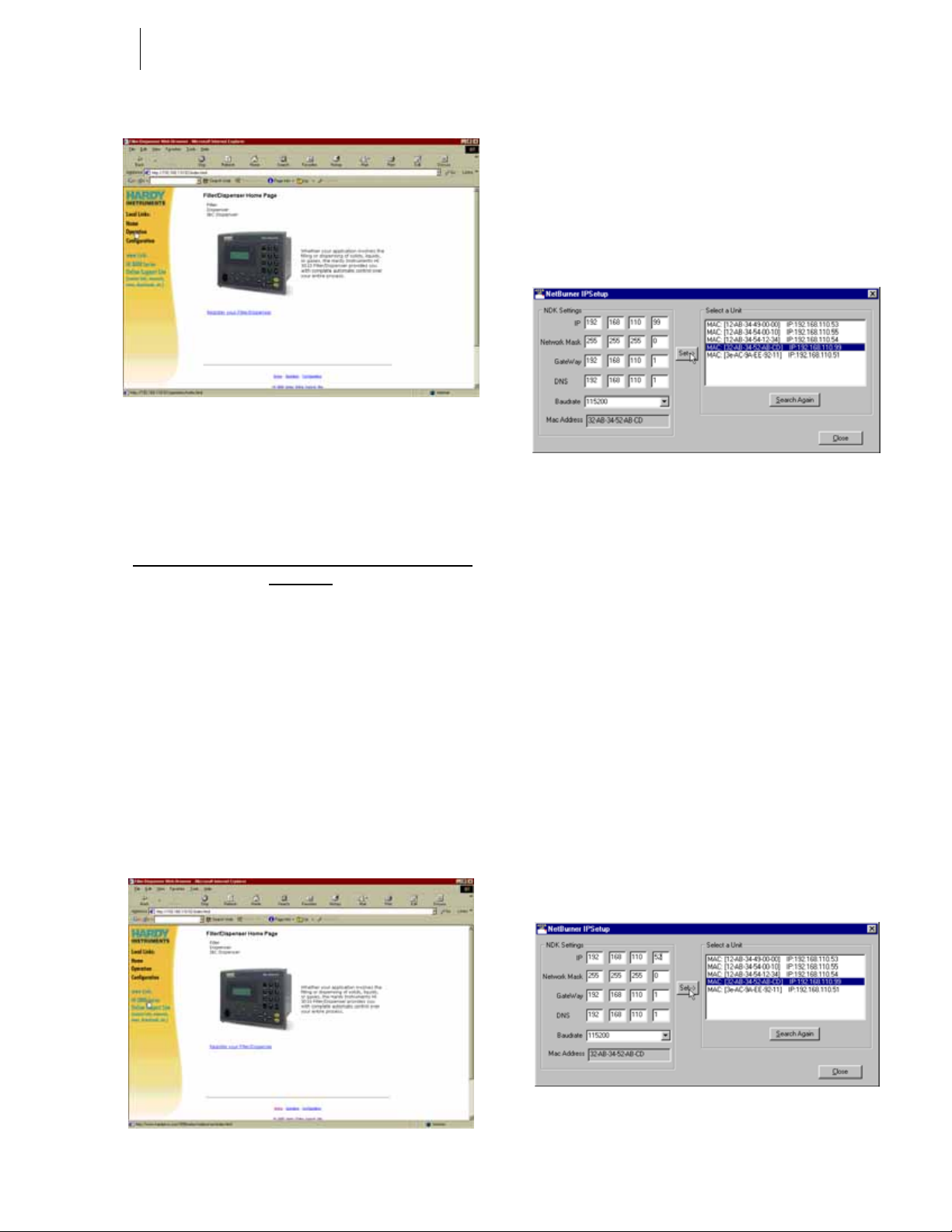
15 Cabling
Installation
FIG. 32: WEB PAGE
Setting the IP Address for the Blind Remote
Since the Blind Remote does not have a keypad you will
have to set the IP Address by via the Ethernet (TCP/IP).
Setting or Changing the IP Address using the
Ethernet
Software Requirements:
IP Setup
Step 1. Get the CD ROM that came with HI 3000 Series
Instrument and load it into to your CD Drive.
Step 2. If you don’t have the CD or can’t find it, you can
connect to the HI 3000 Instrument Web Site by
opening the Instrument Web page and clicking on
the “www.Link: HI 3000 Series Online Support
Site” link. (See Fig. 33) Click on Downloads/IP
Setup.
• On the CD is a folder called Web-Link.
• Open the Folder to get this File “IPSetup.exe”
• When saving the file from our Web Site,
save it to this folder.
• Load “IPSetup.exe” on your hard drive.
• Double click on “IPSetup.exe”. The IP
Setup Dialog box appears. (See Fig. 34)
FIG. 34: IP SETUP MENU
Step 3. IP Setup automatically searches the network for all
the HI 3000 instrument IP addresses that are on the
network. Keep in mind the computer that has the IP
Setup application must be connected to the same
network as the devices.
Step 4. In the Select a Unit field, click on the unit IP
address that you want to change. You will notice
that we clicked on a default address:
192.168.110.99. This means that there is a new HI
3000 Series instrument on the network. The highlighted address also appears in the NDK Settings/
IP.
Step 5. Contact your Network Administrator for the correct
IP Address for this unit.
Step 6. Click in each IP address field that you want to
change. REMEMBER DO NOT DUPLICA TE IP
ADDRESSES. Type in the new IP Address. In our
example we changed “192.168.110.99” to
“192.168.11 0.52”. (See Fig. 35)
FIG. 33: INSTRUMENT WEB PAGE
FIG. 35: IP SETUP/SETTING NEW ADDRESS
Page 30
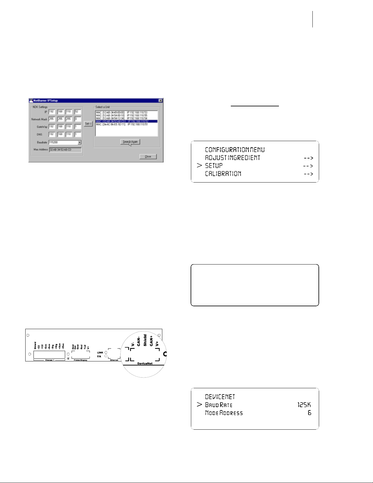
HI-3000 Series 16
>
SE TU P ME N U
Set LC D Contr ast
D evicenet O N ->
Operation and Installation
Step 7. Click on the Set button. The old address will disap-
pear.
Step 8. Reset the HI 3000 Instrument by cycling the power
off and on.
Step 9. Press the Search Again button. The new address
appears in the Select a Unit field. (See Fig. 36)
FIG. 36: NEW IP ADDRESS IS RESET
Step 10. The IP Address has been reset.
DeviceNet Connection and Setup From the Front Panel
Hardware Requirements:
DeviceNet Cable
Software Requirements:
• CAN+ White
•V+ Red
Step 1. Connect the Cable to the connector using the color
code.
Step 2. Connect the cable connector to the DeviceNet con-
nector at the rear panel. (See Fig. 37)
For HI 3010 Only
Step 1. At the front panel click on the Setup button. The
Configuration Menu appears. (See Fig. 38)
FIG. 38: CONFIGURATION MENU/SELECTING
SETUP
Step 2. Push the up or down arrows until the cursor is next
to “SETUP”. (See Fig. 38)
Step 3. Press the Enter button. The Setup submenu appears.
Step 4. Press the up or down arrows until the cursor is in
front of “Devicenet”. (See Fig. 39)
RSNetWorx™
RSLinx™
Hardy EDS File
NOTE: RSNetWorx™ and RSLinx ™ are trademarks of
Rockwell Software.
FIG. 37: REAR PANEL/DEVICENET CONNECTION
CAUTION: D
AN EXTERNAL POWER SOURCE ON THE DEVICENET BUS.
Cable color Code for DeviceNet connector:
O NOT CONNECT V- AND V+ IF YOU HAVE
• V- Black
• CAN- Blue
• Shield Ground Wire
E ther net. ON - >
FIG. 39: SETUP MENU/SELECTING DEVICENET
Step 5. To toggle Devicenet on or off press the right or left
arrow buttons. Notice when Devicenet is toggled
ON there is an arrow to the right of “ON”. The
arrow indicates another sub menu.
Step 6. Press the Enter button. The Devicenet sub-menu
appears. (See Fig. 40)
FIG. 40: DEVICENET SUB-MENU/SETTING THE
BAUD RATE
Page 31

17 Cabling
>
CO NFIGURATION M ENU
CALIBRATIO N ->
O P TIO N S - >
>
OPTIONS MENU
Re mote I / O
D evicenet I/ O ON ->
Installation
Step 7. Use the up or down arrow to move the cursor in
front of “Baud Rate”. (See Fig. 40)
Step 8. Use the left or right arrows to move through the
Baud Rate list. There are 3 baud rates to choose
from:
125 K
250K
500K
Step 9. Once you have made the Baud Rate selection press
the Enter button to set the parameter in the instrument.
Step 10. Use the down arrow to move cursor in front of
“Node Address”. (See Fig. 41)
Step 11. Use the left or right arrows to move the scroll list.
Nodes number from 0 to 64.
FIG. 41: DEVICENET/SELECTING NODE ADDRESS
Step 12. When you have selected the correct node number
for the HI 3000 instrument, press the Enter button.
Step 13. Press the Exit button until you are back to the
standby display.
I/ O MAPPING ->
FIG. 43: CONFIGURATION MENU
Cont r ol N et I/ O OFF ->
FIG. 44: OPTIONS MENU/SELECTING DEVICENET
I/O
Step 4. To toggle Devicenet on or off press the right or left
arrow buttons. Notice when Devicenet is toggled
ON there is an arrow to the right of “ON”. The
arrow indicates another sub menu.
Step 5. Press the Enter button. The Devicenet sub-menu
appears. (See Fig. 45)
For HI 3030, HI 3600, HI 3300
Step 1. At the front panel click on the Setup button. The
Configuration Menu appears. (See Fig. 42)
FIG. 42: CONFIGURATION MENU/SELECTING
SETUP
Step 2. Push the up or down arrows until the cursor is next
to “OPTION”. (See Fig. 43)
Step 3. Press the Enter button. The Options sub-menu
appears. (See Fig. 44)
FIG. 45: DEVICENET SUB-MENU/SETTING THE
BAUD RATE
Step 6. Use the up or down arrow to move the cursor in
front of “Baud Rate”. (See Fig. 45)
Step 7. Use the left or right arrows to move through the
Baud Rate list. There are 3 baud rates to choose
from:
125 K
250K
500K
Step 8. Once you have made the Baud Rate selection press
the Enter button to set the parameter in the instrument.
Step 9. Use the down arrow to move cursor in front of
“Node Address”. (See Fig. 46)
Step 10. Use the left or right arrows to move the scroll list.
Nodes number from 0 to 64.
Page 32

FIG. 46: DEVICENET/SELECTING NODE ADDRESS
Step 11. When you have selected th e correct node num ber
for the HI 3000 instrument, press the Enter button.
Step 12. Press the Exit button until you are back to the
standby display.
HI-3000 Series 18
Operation and Installation
Option Slot 1
Option Slot 0
ControlNet Option Card Installation
CAUTION: MAKE SURE THAT YOU USE AN ANTI-STATIC
STRAP WHEN INSTALLING THE CONTROLNET OPTION
C
ARD.
Step 1. Position the ControlNet Option Card with the back
plane connector facing Option Slot #0. (See Fig.
47)
NOTE: You can only use Opt ion Sl ot #0 when installing
the ControlNet card.
FIG. 48: CONTROLNET/SLIDE INTO OPTION SLOT
#0
Step 3. Push the ControlNet card up against the back plane
and gently press until the card connector seats in the
back plane connector.
Step 4. Use a phillips head screw driver and install the two
(2) screws that fasten the ControlNet card panel to
the HI 3000 Instrument Chassis. (See Fig. 49)
Step 5. Tighten the screws until the ControlNet panel is
snug. Do not overtighten.
Step 6. Connect the BNC ControlNet cables to the BNC
connectors on the ControlNet Option Card.
NOTE: When installing the ControlNet Option Card with
the HI 3000-RC (NEMA 4X rear cover) you must
use a 90° elbow connector on the ControlNet
cable to clear the rear cover.
FIG. 47: CONTROLNET/OPTION CARD
Step 2. Slide the ControlNet Option Card into Slot #0. (See
Fig. 48)
Page 33

19 Cabling
O
1
2
3
4
5
6
7
8
9
O
2
3
5
6
7
8
Installation
FIG. 49: CONTROLNET OPTION CARD INSTALLED
Removing the ControlNet Option Card
Step 1. Disconnect the BNC connectors or RS-45 connec-
tor.
Step 2. Use a phillips head screw driver and remove the
two (2) screws that fasten the ControlNet Option
Card panel to the HI 3000 Chassis.
Step 3. Using the thumb and index finger on both hands,
grasp the two (2) knobs on the card panel and pull
away from the instrument.
Step 4. When the ControlNet Option Card clears the chas-
sis, store in a static free, safe location.
Four versions of Network Taps provide flexible mounting
options: "Y", "T", straight or 90° elbow (right angled).
FIG. 50: CONTROLNET CABLE ASSEMBLIES
Step 1. For normal operation connect the Cable to either
one of the BNC Connectors on the HI 3000 ControlNet Card located at the rear panel of the HI 3000
Series module. (See Fig. 52)
NOTE: Changing the rotary switches to an address other
than 0, 0 - ControlNet will not work. (See Fig. 51)
1
9
4
ControlNet Connection and Setup
Hardware Requirements:
• Hardy ControlNet Card.
• ControlNet Cable with BNC Connectors
on both ends.
Software Requirements:
•RSNetWorx™
• RSLinx™
• Hardy EDS File (A vailable on the HI 3000
CD or current EDS file can be downloaded
from Hardy Website.)
NOTE: RSNetWorx™ and RSLinx ™ are trademarks of
Rockwell Software.
FIG. 51: ROTARY SWITCHES/SETTING NODE
ADDRESS TO 0, 0
Step 2. For redundant operation you need to connect to
both BNC connectors.
FIG. 52: REAR PANEL CONTROLNET CONNEC-
TORS AND LEDS
Page 34

Step 3. Connect the cable connector to the BNC connector
>
Re mot e I/ O OFF
Cont r ol N et I/ O ON ->
on the ControlNet Module or the BNC connector on
the ControlNet Interface card in your PC.
Setting the ControlNet Node Address from the Front Panel
Step 1. At the front panel click on the Setup/3 button. The
Configuration Menu appears. (See Fig. 53)
FIG. 53: CONFIGURATION MENU/SELECTING
SETUP
Step 2. Push the up or down arrows until the cursor is next
to “OPTIONS”. (See Fig. 54)
HI-3000 Series 20
Operation and Installation
FIG. 56: CONTROLNET I/O MENU/SETTING NODE
ADDRESS
Step 6. Press the right or left arrow buttons to select the
Node Address. Left arrow decreases the number
and the right arrow increases the number. Nodes
number from 1-99.
Step 7. Press the Enter button to save the setting.
Step 8. Press the Exit button until you are back to the Main
Menu.
Activating ControlNet and Setting the ControlNet Node Address from the Web Page
Step 1. From the Home Page click on Configuration. (See
Fig. 57) The Configuration page appears. (See Fig.
58)
FIG. 54: CONFIGURATION MENU/SELECTING
OPTIONS
Step 3. Press the Enter button. The Options submenu
appears. (See Fig. 55)
Step 4. If the cursor is not in front of “ControlNet I/O”,
push the down arrow until the cursor is aligned with
ControlNet I/O.
Step 5. Press the Enter button. The ControlNet I/O Menu
appears. (See Fig. 56)
OPTIONS
FIG. 55: OPTIONS/SELECTING CONTROLNET I/O
FIG. 57: HOME PAGE/SELECTING CONFIGURA-
TION
Page 35

21 Cabling
Installation
FIG. 58: CONFIGURATION PAGE/SELECTING
OPTIONS
Step 2. Click on Options. The Options page appears. (See
Fig. 59)
FIG. 60: CONTROLNET PAGE/ACTIVATING CON-
TROLNET
Step 4. Click on the Communication pull down menu.
Step 5. To activate communications click on YES. To deac-
tivate communications click on NO. Since you
want to activate communications, click on YES.
FIG. 59: OPTIONS PAGE/SELECTING VIEW CON-
TROLNET CONFIGURATION
Step 3. Click on View ControlNet Configuration. The Con-
trolNet Configuration page appears. (See Fig. 60)
FIG. 61: CONTROLNET CONFIGURATION PAGE/
ENTERING NODE ADDRESS
Step 6. Click in the Node text field. (See Fig. 61)
Step 7. Type in the Node address for the instrument you are
configuring. In our example we used Node Address
#2. (See Fig. 62)
Page 36

HI-3000 Series 22
Operation and Installation
Color Frequency Description
Red/Green - See Table 5
TABLE 6: LED 3 - LED CHANNEL B
Color Frequency Description
Green Steady on A connection is opened against the
ControlNet Module
Off - No connection is opened
FIG. 62: CONTROLNET CONFIGURATION/ENTER-
ING NODE ADDRESS
Step 8. Click on the Set Parameters button to save the set-
tings.
Step 9. Click on the left arrow or the word “home” at the
bottom of the page to return to the Home Page.
LED Status Indicators
The ControlNet Card is fitted with four bi-color status and
indicator LED’s. (See Fig. 88) During startup the Module
Status (LED 1) and the Module Owned (LED 4) are red for
one (1) second to indicate they are working properly. After
the one second period they are lit as specified below in the
tables. After the module is initialized, the network LED’s
will flash red/green for one (1) second, indicating a self test
of the network chip.
Color Frequency Description
Green Flashing Module is waiting for initialisation
Green Steady on Module is initialized
Red Flashing Minor fault, MacID has been changed
after initialisation, etc.
Red Steady on Major fault, module must be restarted
TABLE 4: LED 1 - MODULE STATUS
TABLE 7: LED 4 - MODULE OWNED
Channel LED’s Description
A & B, steady off Module is not initialized
A & B, steady red Faulted unit, must be restarted or
repaired
A & B, alternating red/green Selftest of bus controller
A&B, flashing red Incorrect node configuration, dupli-
cate MacID, etc.
A or B, steady off Channel is disabled, depending on
network configuration
A or B, steady green Normal operation of channel
A or B, flashing green Temporary errors (node will self cor-
rect) or node is not configured to go
online
A or B, flashing red Media fault or no other nodes on the
network
A or B, flashing red/green Incorrect network conf iguration
TABLE 8: CHANNEL LED’S
For information on setting up the module using RSLogix
5000 and RSNetworx go to the Network Section of this manual.
Color Frequency Description
Red/Green - See Table 5
TABLE 5: LED 2 - LED CHANNEL A
EtherNet/IP™ Option Card Installation
CAUTION: MAKE SURE THAT YOU USE AN ANTI-STATIC
STRAP WHEN INSTALLING THE ETHERNET/IP OPTION
C
ARD.
NOTE: The dip switches do not function. It is a good idea
to leave all of them in the OFF position. Should
you accidentally turn on a dip switch nothing will
happen. The IP address is configured by the firm-
Page 37

23 Cabling
Installation
ware which overwrites any and all dip switch settings.
Step 1. Position the EtherNet/IP Option Card with the back
plane connector facing Option Slot #0 or Option
Slot #1. (See Fig. 63)
FIG. 63: ETHERNET I/P/OPTION CARD
Step 2. Slide the EtherNet/I/P Option Card into Slot #0.
(See Fig. 64)
FIG. 65: ETHERNET/IP OPTION CARD INSTALLED
Step 5. Tighten the screws until the EtherNet I/P panel is
snug. Do not overtighten. Recommended 10 inch/
lbs torque.
Step 6. Connect an approved EtherNet/IP (shielded, double
shielded, waterproof, etc.) cable to the EtherNet I/P
RJ 45 connector on the EtherNet I/P Option Card.
FIG. 64: ETHERNET/I/P/SLIDE INTO OPTION SLOT
#0
Step 3. Push the EtherNet/I/P card up against the back
plane and gently press until the card connector seats
in the back plane connector.
Step 4. Use a phillips head screw driver and install the two
(2) screws that fasten the EtherNet/I/P card panel to
the HI 3000 Instrument Chassis. (See Fig. 65)
NOTE: Do not use standard ethernet cable that you can
buy from a local computer store.
Removing the EtherNet/IP Option Card
Step 1. Disconnect the EtherNet/IP RJ-45 connectors.
Step 2. Use a phillips head screw driver and remove the
two (2) screws that fasten the EtherNet/IP Option
Card panel to the HI 3000 Chassis.
Step 3. Using the thumb and index finger on both hands,
grasp the two (2) knobs on the card panel and pull
away from the instrument.
Step 4. When the EtherNet/IP Option Card clears the chas-
sis, store in a static free, safe location.
Setting Up the EtherNet I/P Address from the Front
Panel
Step 1. At the front panel click on the Setup/3 button. The
Configuration Menu appears.
Step 2. Push the up or down arrows until the cursor is next
to “OPTIONS”. (See Fig. 66)
Page 38

>
CO NFIGURATION M ENU
CALIBRATIO N ->
O P TIO N S - >
I/ O MAPPING ->
>
OPTIONS MENU
Pr of ibus I/ O OFF
E ther net/ IP I/ O ON - >
Smar t Diag. C tr l . - >
>
Addr . 110.110.120.53
Ma s k 255 . 2 55.255.0
G ate 110.110.120.1
FIG. 66: CONFIGURATION MENU/SELECTING
OPTIONS
Step 3. Press the Enter button. The Options submenu
appears. (See Fig. 67)
Step 4. If the cursor is not in front of Ethernet/IP I/O, push
the down arrow until the cursor is aligned with EtherNet/IP I/O.
Step 5. Press the Enter button. The EtherNet/IP I/O Menu
appears. (See Fig. 68)
HI-3000 Series 24
Operation and Installation
trator before changing the Mask address for the cor-
rect Mask Address.
Step 11. Press the Enter button to save the setting if you
changed the setting.
Step 12. Press the right or left arrow buttons until the cursor
is in front of Gate.
Step 13. Use the alphanumeric keypad to enter the EtherNet/
IP Gate address. You normally should not have to
change this address, however, the gate address
sometimes can be different than the default Gate
address. Be sure to contact your Network Adminis-
trator, before changing the Gate address, for the
correct Gate Address.
Step 14. Press the Enter button to save the setting if you
changed the setting.
Step 15. Press the Exit button until you are back to the Main
Menu.
Setting Up the EtherNet I/P Address from the Web Page
FIG. 67: OPTIONS/SELECTING ETHERNET/IP I/O
ET HERNET / IP
FIG. 68: ETHERNET/IP MENU/SETTING IP
ADDRESS
Step 6. Press the right or left arrow buttons until the cursor
is in front of Addr. (See Fig. 68)
Step 7. Use the alphanumeric keypad to enter the EtherNet/
IP Internet Protocol address.
NOTE: This address is different from the HI 3000 Series
IP address.
Step 1. Connect to the HI 3000 by using the IP address for
the instrument. (See Fig. 69)
FIG. 69: HI 3000 HOME PAGE/SELECTING CONFIG-
URATION
Step 2. Click on Configuration. The Configuration page
appears. (See Fig. 70)
Step 3. Click on Options. The Options page appears. (See
Fig. 71)
Step 8. Press the Enter button to save the setting.
Step 9. Press the right or left arrow buttons until the cursor
is in front of Mask.
Step 10. Use the alphanumeric keypad to enter the EtherNet/
IP Mask address. You normally should not have to
change this address, however, the mask address
sometimes can be different than the default Mask
address. Be sure to contact your Network Adminis-
Page 39

25 Cabling
ON
Connector
Switches
Installation
Step 6. Type in the new IP address.
Step 7. If necessary repeat steps 6 & 7 for the Network
Mask and Gateway.
Step 8. Click on the Set Parameters button to save the
parameters.
Step 9. Click on the left arrow or the word “home” at the
bottom of the page to return to the Home Page.
LED Status Indicators
FIG. 70: CONFIGURATION PAGE/SELECTING
OPTIONS
FIG. 71: OPTIONS PAGE/SELECTING VIEW ETH-
ERNET/IP CONFIGURATION
RJ 45
12345678
Dip
LED 1
LED 2
LED 4
LED 3
FIG. 73: CONNECTOR/DIP SWITCHES/LEDS
The Ethernet/IP Card is fitted with four bi-color status and
indicator LED’s. (See Fig. 115) During startu p the Module
Status (LED 2) and Network Status (LED 3) are red for one
(1) second to indicate they are working properly. After the
one second period they are lit as specified below in the
tables. The HI 3000 Series products use the default settings.
LED 1 - Link (Activity)
• LED 1 Configuration
Color State Indicates:
Green Steady On Module has a link
Step 4. Click on View EtherNet/IP config urati on. ( See F ig.
113) The EtherNet/IP page appears. (See Fig. 72)
FIG. 72: ETHERNET/IP PAGE/SETTING IP
ADDRESS
Step 5. Click in the IP Address text field. Delete the current
IP Address.
Green Steady Off Module does not sense a link
TABLE 9: LED 1 - MODULE STATUS/CONFIGURATION
LED 2 - Module Status
• LED 2 Configuration
State Summary Description
Steady Off N o Power No power applie d to the mo d ule
Steady Green Device
Operational
Flashing
Green
Flashing Red Minor Fault A minor recoverable fault has been
Standby The module has not been configured
TABLE 10: LED 2 CONFIGURATION
The module is operating properly
detected
Page 40

HI-3000 Series 26
SIEMENS
Operation and Installation
State Summary Description
Steady Red Major Fault A major internal error has been
detected
Flashing
Green/Red
Self-Test The module is performing a power on
self test
TABLE 10: LED 2 CONFIGURATION
LED 3 - Network Status
• LED 3 Configuration
State Summary Description
Steady Off No Power
Steady Green Connected The module has at least on estab-
Flashing
Green
Flashing Red Connec-
or no IP
address
No Connections
tion Timeout
The module has no power or no IP
address has been assigned
lished EtherNet/IP connection
There are no EtherNet/IP connections
established to the module
One of more of the connections in
which this module is the target has
timed out. This state is only left if all
timed out connections are re-established or if the module is reset.
Step 4. Use a phillips head screw driver and install the two
(2) screws that fasten the Profibus card panel to the
HI 3000 Instrument Chassis.
Step 5. Tighten the screws until the Profibus panel is snug.
Do not overtighten.
Profibus Connection and Setup
Hardware Requirements:
• Hardy Profibus Option Card
• Profibus Cable with DB9 Serial Connectors on both ends. It is recommended that
you use a Serial Connector with a slide
switch to terminate an instrument that is
located at the end of a Fieldbus (Profibus)
Network. (See Fig. 74)
NOTE: The Profibus-DP cable must conform to the
PROFIBUS-DP EN 50 170 Specification for
Cable.
Slide
Switch
ON OFF
Steady Red Duplicate IPThe module has detected that its IP
address is already in use
Flashing
Green/Red
Self-Test The module is performing a power on
self test
TABLE 11: LED 3 CONFIGURATION
LED 4 - Activity
• LED 4 Configuration - This LED flashes
green each time a packet is received or
transmitted.
Profibus Option Card Installation
CAUTION: MAKE SURE THAT YOU USE AN ANTI-STATIC
STRAP WHEN INSTALLING THE PROFIBUS OPTION CARD.
Step 1. Position the Profibus Option Card with the back
plane connector facing Option Slot #0.
NOTE: You can only use Opt ion Sl ot #0 when installing
the Profibus.
Step 2. Slide the Profibus Option Card into Slot #0.
Step 3. Push the Profibus card up against the back plane
and gently press until the card connector seats in the
back plane connector.
FIG. 74: PROFIBUS DB9 SERIAL CONNECTOR
WITH SLIDE SWITCH/MALE
Software Requirements:
• Siemens Step 7™, Simatic Manager or
equivalent.
• Hardy *.GSD File (Available on the HI
3000 CD or current.GSD file can be downloaded from the Hardy Website (http://
www.hardyinst.com) or the Profibus Web
Site (http://www.profibus.com/libraries.html)
Cabling Guidelines
1. The Trunk Line is the main network cable and anchors
the two ends of the network.
2. A Drop Line is the network branch cable between the
trunk line tap or junction box and the HI 3000 Series
instrument. The baud rate selection can affect and/or
restrict each of the following variables:
Page 41

27 Cabling
9
O
1
2
3
4
5
6
7
8
9
O
2
3
4
5
6
7
8
Installation
NOTE: A trade off between the longest length of Trunk
and Drop cable that can be used and the selected
data transfer speed. Baud rate selection
Pin Name Function
• The available number of network nodes.
• The total overall length of the Trunk Line.
• The type of cable used for the Trunk Line.
• The sum total length of all individual drop
lines.
Cable Specification
The specifications for Profibus standard Type A cable are
provided in Table 8. This type of cable is recommended for
transmission speeds above 500k baud, and any long distance
installations.
Impedance 35 up to 165 ohm at frequencies from 3 to 20 Mhz
Cable Capacity <30 pF per meter
Cable Diameter >0.34 mm2, corresponds to AWG 22
Cable Type Twisted pair cable, 1x2 or 2x2 or 1x4 lines.
Resistance <110 ohm per km
Signal
Attenuation
Shielding CU shielding braid or shielding braid and shield-
max 9dB over total length of line section
ing foil.
Housing Shield Connected to PE
1 Not Connected -
2 Not Connected -
3 B-Line Non-inverting RxD/TxD
4 RTS Request to send
5 GND BUS GND from RS485
6 +5 V BUS +5 V from RS485
7 Not Connected -
8 A-Line Inverting RxD/TxD
9 Not Connected -
TABLE 13: 9-PIN DSUB CONNECTOR
Step 2. Use a slotted head screw driver and configure the
Node address of the Instrument by setting the flats
of the rotary switches so that they are pointing to
zero (0,0). (See Fig. 76)
NOTE: Changing the rotary switches to an address other
than 0, 0 - Profibus will not work. (See Fig. 76)
Max Bus
Length
Step 1. Connect the Profibus cable connectors to the DB9
female serial connector on the Profibus Option
Card. (See Fig. 75)
200 m at 1500 kbit/second; up to 1.2 km at 93.75
kbit/second. Maximum length may be extended
with installation of repeater devices.
TABLE 12:
1
9
x 10 x 1
51
FIG. 76: ROTARY SWITCHES/SETTING NODE
ADDRESS TO 0, 0
6
Female Connector on the
Hardy Profibus Option Card
FIG. 75: DB9 CONNECTOR ON THE HARDY PROFI-
BUS OPTION CARD
Page 42

HI-3000 Series 28
1
4
Operation and Installation
LED Indicators
2
3
FIG. 77: LED INDICATORS
1. LED #1 - Application Communication Status LED
• Not Used/Always Off
2. LED #2 - Fieldbus On-line
• LED #2 indicates if the module is On-Line
or not. If the module is On-Line and data
exchange is possible the LED is green.
LED State Indicates
• The LED indicates certain faults on the
fieldbus side.
LED State Indicates
Off -No diagnostics Present
-No power to the module.
Flashing Red 1 Hz Bus is Off-Line. Fieldbus Config Error running
bit set in AnyBus status
Flashing Red 2 Hz Error in parameter data. Fieldbus Config Error
bit set in AnyBus status
Flashing Red 4 Hz Error in initialization of the Profibus communi-
cation ASIC. Fieldbus ASIC Error bit set in
AnyBus status
TABLE 16: LED #4 - FIELDBUS DIAGNOSTICS
Removing the Profibus Option Card
Step 1. Disconnect the DB9 Serial connector.
Step 2. Use a phillips head screw driver and remove the
two (2) screws that fasten the Profibus Option Card
panel to the HI 3000 Chassis.
Step 3. Using the thumb and index finger on both hands,
grasp the two (2) knobs on the card panel and pull
away from the instrument.
Step 4. When the Profibus Option Card clears the chassis,
store in a static free, safe location.
Off -Bus is not On-Line
-No power to the Module
Green Bus is On-Line and data exchanges is
TABLE 14: LED #2 - FIELDBUS ON-LINE
3. LED #3 - Fieldbus Off-Line
• The LED indicates that the module is Off-
LED State Indicates
Off -Bus is not Off-Line
Red Bus is Off-Line, fieldbus running bit
TABLE 15: LED #3 - FIELDBUS OFF-LINE
possible. Fieldbus
Line and is the opposite of LED #2. If the
module is Off-Line and no data exchange
is possible, this LED is red, otherwise it is
turned off.
-No power to the module
cleared in AnyBus status.
NOTE: For Configuration instructions see the Network/
Profibus I/O section of this manual. The installation for all HI 3000 Series instruments is the
same.
Analog Output Option Card Installation
CAUTION: MAKE SURE THAT YOU USE AN ANTI-STATIC
STRAP WHEN INSTALLING THE ANALOG OPTION CARD.
Step 1. Position the Analog Option Card with the back
plane connector facing Option Slot #0 or Option
Slot #1. (See Fig. 78)
4. LED #4 - Fieldbus Diagnostics
Page 43

29 Cabling
Outpu t 1 Outpu t 2
Shield
V-
V+
I-
I+
Current
Installation
Electrical Connection
Step 1. If you are using a current output (4-20 milliamp)
connect the positive and negatives wires to the -I
and +I pins. (See Fig. 80)
Volta ge
FIG. 78: ANALOG OUTPUT OPTION 2AN
NOTE: You can only use Option Slot #1 if either the RIO
Option or the ControlNet Option cards are
installed.
Step 2. Slide the Analog Option Card into Slot #0 or Slot
#1. (See Fig. 79)
V-
V+
I-
I+
Shield
2AN
FIG. 80: ANALOG ELECTRICAL CONNECTIONS
Step 2. If you are using a voltage output (0-10 Volts) con-
nect the positive and negative voltage wires to the (V and +V pins).
Step 3. Connect ground to the Shield pin.
CAUTION: D
RENT TO ONE OUTPUT CONNECTOR. IF YOU WANT VOLT-
AGE AND CURRENT OUTPUT IN THE SAME INSTRUMENT
YOU MUST WIRE THEM TO SEPARATE OUTPUT CONNEC-
TORS.
O NOT CONNECT BOTH VOLTAGE AND CUR-
Removing the Analog Option Card
FIG. 79: INSTALLING THE ANALOG OPTION CARD
Step 3. Push the Analog card up against the back plane and
Step 4. Use a phillips head screw driver and install the two
Step 5. Tighten the screws until the Analog panel is snug.
NOTE: If you want 4 Analog outputs, install 2 Analog
IN A 3000 CHASSIS
gently press until the card connector seats in the
back plane connector.
(2) screws that fasten the Analog card panel to the
HI 3000 Instrument Chassis.
Do not overtighten.
Output Option cards, one in Option Slot #0 and
one in Option Slot #1.
Step 1. Disconnect the connector from the terminal block.
Step 2. Use a phillips head screw driver and remove the
two (2) screws that fasten the Analog Option Card
panel to the HI 3000 Chassis.
Step 3. Using the thumb and index finger on both hands,
grasp the two (2) knobs on the card panel and pull
away from the instrument.
Step 4. When the Analog Option Card clears the chassis,
store in a static free, safe location.
NOTE: For Configuration and Mapping instructions see
the individual HI 3000 product Technical man uals, Configuration Section (Chapter 4). The
installation for all HI 3000 Series instruments is
the same.
Rear Cover Installation (HI 3000-RC)
Rear cap for the HI 3000 Series controllers. Upgrades the
entire assembly to a NEMA 4X rating by enclosing all the
rear panel connectors. (See Fig. 123) You will need to install
the Cable Grip Assemblies and cabling before installing the
Rear Cover.
Page 44

The HI 3000-RC comes standard with the following parts:
Plug
Cord Grip
Assembly
• (1) Rear Cover
• (1) Rear Cap Gasket
• (4) Machine Screws, Panhead, #6-32
x.38L
• (1) NEMA 4, 1” Plug
• (2) Cord Grip, PG-11 THD
• (2) Hex Nuts, PG-11 THD, 26 mm Dia.
HI-3000 Series 30
Operation and Installation
NEMA 4
NOTE: To purchase additional NEMA 4 plugs, hex nuts
and Cord Grips contact your local Hardy Representative.
NEMA 4 Plug
Cord Grips
FIG. 81: NEMA 4X REAR COVER
Removing the NEMA 4 Plug
FIG. 82: INSTALLING NEMA 4 PLUG
Installing the Cord Grip Assemblies
Step 1. If you are installing the grips into a pre-existing
hole, do the following:
• If there is a NEMA 4 plug installed,
remove it. (See “Removing NEMA 4
Plug” above for instructions)
• Slide the Cord Grip Assembly into the
hole in the rear cover. (See Fig. 83)
Hex Nut
CAUTION: D
REMOVING OR INSTALLING THE NEMA 4 PLUG. USING
SHARP OBJECTS MAY DAMAGE THE PLUG AND MAY
DESTROY THE NEMA 4X SEAL.
O NOT USE ANY SHARP OBJECTS WHEN
Step 1. From the inside of the Rear Cover, using your fin-
ger, gently push the middle of the plug toward the
rear cover until the plug releases.
Step 2. Store in a secure location or place in an empty hole
to maintain the rear cover NEMA 4 seal.
Installing the NEMA 4 Plug
Step 1. Place the plug over the hole. (See Fig. 82)
Step 2. Gently press the NEMA 4 plug toward the rear
cover until the plug is snug against the outside surface of the rear cover and snaps into place.
FIG. 83: INSTALLING THE HEX NUT ONTO THE
CORD GRIP ASSEMBLY
• Screw the Hex Nut onto the threaded end
of the Cord Grip Assembly until it is finger tight and the cord grip assembly is
flush against the outside surface of the rear
cover. (See Fig. 84)
Page 45

31 Cabling
Cord Grip
Assembly
Installation
Cord Grip
FIG. 84: CORD GRIP INSTALLED
• Use a box end wrench to hold the cord grip
assembly nut so that it doesn’t move when
tightening the Hex Nut.
• Use a box end wrench to tighten the Hex
Nut until the Cord Grip assembly is snug
against the rear cover. Do not over tighten.
Step 2. If you are installing a Cord Grip Assembly into a
location which requires drilling a hole into the rear
cover do the following:
Hex Nut
FIG. 85: INSTALLING THE HEX NUT ONTO THE
CORD GRIP ASSEMBLY
• Screw the Hex Nut onto the threaded end
of the Cord Grip Assembly until it is finger tight and the cord grip assembly is
flush against the outside surface of the rear
cover. (See Fig. 86)
• Locate the indent that is closest to the connector you want to connect to.
• A 1” inch diameter hole is required when
using Hardy Cord Grip Assemblies.
• Place the rear cover on a secure, flat surface preferably a drill press table.
• Place a wooden block under the location
of the hole you want to drill. This will prevent ragged edges from forming when
drilling or using a hole saw.
NOTE: When using a hole saw make sure you use a fine
tooth hole saw and not the coarse tooth hole saw.
CAUTION: D
MAY CRACK THE REAR COVER AND DESTROY THE NEMA
4X
SEAL.
O NOT USE A HOLE PUNCH. A HOLE PUNCH
• Center the drill bit in the preformed centering indent and drill or saw the hole
through the rear cover.
• Use emery cloth and lightly touch up the
inside and outside surfaces of the hole to
remove any burrs.
• Slide the Cord Grip Assembly into the
hole in the rear cover. (See Fig. 85)
Cord Grip
FIG. 86: CORD GRIP INSTALLED
• Use a box end wrench to hold the cord grip
assembly nut so that it doesn’t move when
tightening the Hex Nut.
• Use a box end wrench to tighten the Hex
Nut until the Cord Grip assembly is snug
against the outside surface of the rear
cover.
CAUTION: D
CAN CRACK OR DAMAGE THE REAR COVER.
O NOT OVER TIGHTEN. OVERTIGHTENING
• Slide the cable through the Cord Grip
Assembly. Make sure that you slide
enough of the cable so that you can create
a cable relief bend and connect to the connectors in the rear panel of the instrument.
(See Fig. 87)
Page 46

HI-3000 Series 32
Operation and Installation
FIG. 88: ALIGNING THE REAR COVER TO THE
CHASSIS
FIG. 87: INSTALLING CABLES IN THE CORD GRIP
ASSEMBLY
NOTE: When installing a BNC connector to the Control-
Net Option Card you must use a 90 ° elbow to
allow sufficient room to correctly route the cable.
Removing the Cord Grip Assembly
• Use a box end wrench to hold the cord grip
assembly nut so that it doesn’t move when
loosening the Hex Nut.
• Use a box end wrench to remove the Hex
Nut.
• Slide the Cord Grip out of the rear cover.
• For further disassembly you can use a box
end wrench and remove the Cord Grip
Nut, although it is not necessary for
removal.
• Install a NEMA 4 plug.
Installing the HI 3000-RC Rear Cover
Step 1. Check to see that all the Cable Grips and Cables are
installed.
Step 2. Install the wires into the cord grips in the rear panel.
Step 3. Connect the wires to the connectors on the rear
panel of the HI 3000 instrument.
Step 4. Position the rear cover, pulling the cable if neces-
sary so that the thru holes on the rear cover align
with the threaded holes on the HI 3000 Instrument
chassis. (See Fig. 88)
Step 5. Place the rear cover onto the rear of the Chassis.
Step 6. Use a phillips head screw driver and screw the four
(4) screws into the threaded holes on the rear panel
of the chassis.
Step 7. Tighten the screws until they are snug. There is a
gasket installed in the rear cover which needs to be
slightly depressed to provide a NEMA 4X seal.
CAUTION: D
MAY DAMAGE THE REAR COVER OR THE INSTRUMENT.
O NOT OVERTIGHTEN. OVERTIGHTENING
Step 8. Use a box end wrench and tighten the Cord Grip
Assembly Nut until the cables when tugged do not
come out of the Cord Grip. (See Fig. 89)
Step 9. Install the NEMA 4 plugs in empty holes if neces-
sary. (See Fig. 89)
Page 47

33 Cabling
Plug
Installation
NEMA 4
Cables
FIG. 89: REAR COVER , NEMA 4 PLUGS, AND CORD
GRIPS INSTALLED
Page 48

HI-3000 Series 34
Operation and Installation
Page 49

35 Network
Installation
NETWORK: INSTALLATION
About Networks
The HI 3000 Series Network configurations include:
• Hardy Control-Link (Ethernet 10/100
Base T)
• DeviceNet
• ControlNet
• Profibus DP
• Ethernet/IP
• Modbus TCP/IP
This enables the HI 3000 Series to communicate with virtually every device on the network, including PCs and PLCs.
This means that you can map, configure and monitor all the
HI 3000 series products from the front panel or your LAN,
Internet, DeviceNet, ControlNet and Wireless Servers that
are connected to the Network.
Simple Ethernet Network (See Fig. 90)
Materials Required
• Ethernet Card for your LapTop.
• Ethernet Crossover Cable with RJ45 Connectors on both ends.
• Browser on your Lap Top.
consists of a 3 digit number between 0 and 255.
An IP address consists of 4 octets. The first three
(3) octets identify the network. The 4th octet is
the identifier for the individual node. (See Fig.
91)
FIG. 91: IP ADDRESS CONFIGURATION
Step 2. Connect one of the RJ45 Connectors to the Ethernet
connection at the rear panel of the HI 3000 Series
products.
Step 3. Connect the other RJ45 Connector to the Ethernet
connection on your Laptop Ethernet card or your
Ethernet Adapter. The 10BaseT Cable pinouts are
as follows:
Pin
Colors on one
side of Cable
Colors on other
end of Cable
FIG. 90: SIMPLE HARDY CONTROL-LINK
NETWORK
Step 1. Contact your Network Administrator for the IP
address of the instrument you want to connect to. If
the Instrument does not have an IP address, create
one. (See Cabling: Installation/Ethernet Cable Connection and Setup Section in this manual)
NOTE: To connect to the HI 3000 instrum ent requires
that your laptop IP address be in the same Class
and the same Network Segment. For example if
the IP address of the instrument is 192.168.110.x
you will have to create an IP address for your
laptop that includes the first three octets. An octet
1 Orange/White Orange/White
2 White/Orange White/Orange
3 Green/White Green/White
4 White/Blue White/Blue
5 Blue/White Blue/white
6 White/Green White/Green
7 Brown/White Brown/white
8 White/Brown White/Brown
TABLE 17: PINOU T S FOR 10BASE T STANDARD
CABLE
Pin
Colors on one
side of Cable
1 White/Orange White/Green
Colors on other
end of Cable
TABLE 18: PINOUTS FOR 10BASE T CROSSOVER
CABLE
Page 50

HI-3000 Series 36
Operation and Installation
Pin
Colors on one
side of Cable
2 Orange/White Green/White
3 White/Green White/Orange
4 Blue/White Blue/white
5 White/Blue White/Blue
6 Green/White Orange/White
7 White/Brown White/Brown
8 Brown/White Brown/White
Colors on other
end of Cable
TABLE 18: PINOUTS FOR 10BASE T CROSSOVER
CABLE
Step 4. Start your computer.
Step 5. Click on Start.
Step 6. Click on Settings.
Step 7. Click on Control panel. The Control Panel appears.
Step 8. Click on the Network Icon. (See Fig. 92) The Net-
work dialog box appears. (See Fig. 93)
FIG. 93: NETWORK DIALOG BOX/SELECT TCP/IP
Step 9. Click on the Properties button. (See Fig.94) The
TCP/IP dialog box appears. (See Fig. 95)
Step 10. In the IP address field, type in an IP address. Make
sure that the segment (first three octets) are the
same as the HI 3000 Instrument you are connected
to. For the last octet make sure that the number you
enter is not the node address of any other device on
the network.
FIG. 92: CONTROL PANEL
• To get the IP address of the instrument
from the front panel, go to the Setup Menu
and press the up arrow button until the cursor is in front of Ethernet.
• Press the Enter button. The Ethernet IP
Address appears.
• You can also get the IP address from your
Network Administrator.
Page 51

37 Network
Installation
Step 18. Click on the Internet Options Icon. The Internet
Explorer Properties dialog box appears. (See Fig.
96)
Step 19. Make sure that the Never dial a connection is
checked.
Step 20. Click on OK.
Step 21. Type in the IP address of the HI 3000 series instru-
ment you are connected to and the Product Home
page appears.
FIG. 94: NETWORK DIALOG BOX/SELECT
PROPERTIES
FIG. 95: TCI/IP PROPERTIES/IP ADDRESS
Step 11. Click on OK.
Step 12. Open up your browser.
Step 13. In the Address field in the Browser, type in the IP
Address for the instrument you are connected to.
Step 14. The Product Hom e Page appears.
Step 15. If the Produ ct Hom e Page does not appear.
Step 16. Click on Start.
Step 17. Click on Settings.
FIG. 96: INTERNET PROPERTIES DIALOG BOX
Hardy Control-Link Ethernet Network
FIG. 97: HARDY CONTROL-LINK ETHERNET
NETWORK
Materials Required
• 3, 4, 5, 8 Port Hub (Depends on how many
devices you are going to connect to the
hub.
• 10/100 Base T Ethernet Card for the PC.
Page 52

• Ethernet Cables with RJ45 connectors on
both ends.
Step 1. Connect the Standard Ethernet cables between all
the HI 3000 instruments and the hub or Switch.
Step 2. Connect the a Standard Ethernet cable between the
PC and the Hub or Switch.
Step 3. Create an IP address for each of the HI 3000 Series
instruments and the PC. (See Cabling: Installation/
Ethernet Cable Connection and Setup Section in
this manual). (For the PC see Simple Ethernet Net-
work above.)
Step 4. Start your computer.
Step 5. Start the Browser and type the IP address of the
instrument you want to monitor or configure.
Setting Node Addresses for HI 3000 Series Instruments from the Browser
Step 1. From the HI 3000 Series instrument Home Page
click on Configuration. (See Fig. 98) The Configu-
ration page appears. (See Fig. 99)
HI-3000 Series 38
Operation and Installation
FIG. 99: CONFIGURATION PAGE/SELECTING
HARDY CONTROL-LINK
Step 2. Click on “Hardy Control-Link”. The Configuration
- Hardy-Link Page appears. (See Fig. 100)
NOTE: We are showing the HI 3010 Filler/Dispenser
however all HI 3000 Series instruments are configured the same way.
FIG. 98: FILLER/DISPENSER HOME PAGE/
SELECTING CONFIGURATION
FIG. 100: CONFIGURATION - HARDY CONTROL-
LINK PAGE
Step 3. If other HI 3000 Controllers are attached to the
Hardy Control-Link Network, you can view their IP
addresses by clicking on the “Instrument Selection”
pull down list. All connected devices are listed.
(See Fig. 101)
Page 53

39 Network
Installation
FIG. 101: CONFIGURATION - HARDY CONTROL-
LINK/INSTRUMENT SELECTION PULL DOWN
LIST
FIG. 103: SELECTED INSTRUMENT WITH IP
ADDRESS IN IP ADDRESS FIELD
NOTE: It is always a good practice to assign node 0 to
the instrument you are currently using.
Step 6. Click on the node 0 button to assign the HI-3010 to
Node 0. The IP address and model of the instrument
appear in the Node 0, “Node IP Address”. (See Fig.
104)
Step 4. When you arrive at the Configuration - Hardy Con-
trol-Link page for the first time the Node address
fields have “0.0.0.0” and the Instrument Name
fields indicate “none found” however the instrument you are currently using is displayed in the
Instrument Selection field. (See Fig. 102)
Step 5. To Assign an IP address to a node, click on the
instrument you want to assign to a node in the pull
down list. The IP address of the selected instrument
loads into the IP Address field. (See Fig. 103)
FIG. 104: HI-3010 (IP ADDRESS 192.168.110.68)
ASSIGNED TO NODE 0
Step 7. Repeat Steps 5 and 6 to assign the next instrument
to node 1. (See Figs. 105 & 106)
FIG. 102: CONFIGURATION PAGE WITH
INSTRUMENTS NOT ASSIGNED A NODE ADDRESS
FIG. 105: SELECTED INSTRUMENT WITH IP
ADDRESS IN IP ADDRESS FIELD
Page 54

FIG. 106: HI-3010 (IP ADDRESS 192.168.110.24)
ASSIGNED TO NODE 1
Step 8. Continue assigning instruments to the node
addresses until all the instruments you want in the
table are assigned. (See Fig. 107)
Step 9. Now click in the Talk check boxes to allow the
instruments to communicate with each other. (See
Fig. 107)
HI-3000 Series 40
Operation and Installation
FIG. 108: SAVING THE CONFIGURATION
Step 11. This is an optional procedure but highly recom-
mended. If you want to transfer an exact copy of the
node 0 setup to another node, click in the “Send
Setup to Node” check box of the node you want to
receive the setup of Node 0. (See Fig. 109) In our
example we sent the setup to node 1.
Step 12. Click on the Save Settings button to complete the
transfer.
FIG. 107: INSTRUMENTS ASSIGNED TO NODE 0
THROUGH NODE 7
Step 10. Click on the Save Settings button to save the con-
figuration. (See Fig. 108)
FIG. 109: TRANSFERRING THE NODE
CONFIGURATION FROM NODE 0 TO NODE 1
NOTE: It is a good idea to have the same node setup on
every HI 3000 Series Instrument on your Hardy
Control-Link Network.
Using the Ping Tool
T o troubleshoot the network and instrument configuration go
to Chapter 7 - Troubleshooting in the HI 3000 Series Instrument Service Manual.
Page 55

41 Network
Installation
Devicenet Network Setup
RSNetWorx Setup for HI 3000 Series Instruments
Step 1. Download the Hardy EDS file either from the CD
that came with your instrument or go to the Hardy
Instruments Website to get the most current file. Put
the Hardy EDS file in the Rockwell Software
folder. DO NOT PUT THE EDS FILE IN THE
EDS FOLDER!
Step 2. Start up RSNetWorx.
Step 3. Click on the Tools pull down menu. (See Fig. 110)
Step 4. Click on EDS Wizard. The EDS Wizard dialog box
appears. (See Fig. 111)
FIG. 112: SELECTING “REGISTER AN EDS FILE”
FIG. 110: SELECTING EDS WIZARD
Step 5. Click on Next. The EDS Options dialog box
appears. (See Fig. 112)
Step 6. Click on Next. (See Fig. 112) The Registration dia-
log box appears.
Step 7. Click on the Browse button. The Select EDS file
dialog box appears. Go to the folder that contains
the Hardy EDS file. We put the file in the Rockwell
Software folder. (See Fig. 113)
Step 8. Click on the Hardy EDS file to highlight it.
Step 9. Click on Open. (See Fig. 113)
Step 10. The Registration dialog box reappears with the path
to the Hardy EDS file in the text field. (See Fig.
114)
FIG. 111: EDS WIZARD DIALOG BOX
FIG. 113: SELECTING THE HARDY EDS FILE
Page 56

HI-3000 Series 42
Operation and Installation
FIG. 114: SELECTING THE HARDY EDS FILE
Step 11. Click on Next. The EDS File Installation Test
Results dialog box appears. (See Fig. 115)
Step 12. Cli ck on Next. The Change Graphic Image dialog
box appears. (See Fig. 116)
FIG. 115: EDS FILE INSTALLATION TEST RESULTS
DIALOG BOX
FIG. 116: CHANGE GRAPHIC IMAGE DIALOG BOX
Step 13. Click on Next. The Final Task Summary dialog box
appears. (See Fig. 117)
Step 14. Click on Next. The main page appears with Hardy
listed under Vendor. (See Fig. 118)
FIG. 117: FINAL TASK SUMMARY DIALOG BOX
Page 57

43 Network
Installation
FIG. 118: HARDWARE/VENDOR/HARDY
INSTRUMENTS INC. INSTALLED
Step 1. Double Click on the Hardy Filler Icon. (See Fig.
119) The Hardy Filler Property List appears with
the General Tab selected. (See Fig. 120)
Step 2. Click on the Module tab.
Step 15. Cli c k on the graph tab.
Step 16. Cli c k on the + sign in the box next to Hardy Instru-
ments, Inc. The Communication Adapter folder
flies out.
Step 17. Cli c k on the + sign next to the Com mu nicat ion
Adapter and the Hardy Series 3000 Instrument
appears next to the Instrument Icon. In our example
the Hardy Filler HI-3010.
Step 18. Double click on the Hardy Filler Icon and it appears
in the graph with value 00. (See Fig. 119)
Step 19. The EDS file installation is complete.
FIG. 119: GRAPH/HARDY FILLER ICON
Slave Mode Setup
The DeviceNet Module can operate in Master or Slave
mode. To set the module to the slave mode, perform the following procedures.
FIG. 120: MODULE TAB/SELECTING SLAVE MODE
Step 3. Click on the Slave Mode button. (See Fig. 120) The
Slave Mode dialog box appears. (See Fig. 121)
FIG. 121: SLAVE MODE DIALOG BOX
Step 4. Click in the check box next to “Enable Slave
Mode” to enable the Slave Mode.
Step 5. Under Polled set the number of bytes for the Rx and
Tx Sizes.
Step 6. Click on the OK button.
Step 7. Click on the Input Tab. The Input Page appears.
(See Fig. 122)
Step 8. Click on the AutoMap button to Map the Inputs.
(See Fig. 123)
Page 58

HI-3000 Series 44
Operation and Installation
FIG. 122: INPUT PAGE/SELECTING AUTOMAP
FIG. 123: INPUT PAGE/INPUTS MAPPED
Step 9. Click on the Output Tab. The Output Page appears.
(See Fig. 124)
Step 10. Click on the AutoMap button to Map the Outputs.
(See Fig. 125)
FIG. 124: OUTPUT PAGE/SELECTING AUTOMAP
FIG. 125: OUTPUT PAGE/OUTPUTS MAPPED
Step 11. Click on the OK button to return to the Main Menu.
The Slave Mode is set.
Page 59

45 Network
Installation
Building a Scanlist in RSNetWorx
FIG. 126: GRAPH OF NETWORKED MODULES
Step 1. Double Click on the Hardy Filler Icon. (See Fig.
126) The Hardy Filler Property List appears. (See
Fig. 127) In Properties, you construct the Scanlist,
which includes the devices that will be scanned on
the network.
Step 2. Click on the Scanlist tab. The Scanlist page
appears. (See Fig. 128)
NOTE: It is useful to know what you want to configure/
map at this point of the setup. See Operating the
Instrument V ia DeviceNet/Mapping Section in the
Individual HI 3000 Series manual(s) for this
information.
FIG. 127: HARDY FILLER PROPERTIES LIST
FIG. 128: SCANLIST PAGE/AVAILABLE DEVICES
Step 3. Notice in the Available Devices field there are two
HI 200 DeviceNet Weigh Modules.
Step 4. Click on the device(s) you want to appear on the
scan list.
Page 60

Step 5. Click on the double arrow pointing to the Scanlist
to add the devices to the scanlist. (See Fig. 129)
HI-3000 Series 46
Operation and Installation
FIG. 129: SCANLIST PAGE/SCANLIST
Step 6. There are a few things on the scanlist page to pay
attention to.
• If you want to “Automap on Add”, click
on the check box to select this function.
This enables the scanlist to be attempted.
• In the Electronic Key area there are three
check boxes. When checked, RSNetWorx
remembers what version of the device you
are adding to the scanlist as well as I/O
mapping.
Step 7. Click on the Input Tab. The Input page appears.
(See Fig. 130)
Step 8. Here is where you can change the parameters for
the devices that the HI 3000 Series device is
mapped to. Check you RSNetWorx manual for
instructions.
Step 9. Click on OK and the Scanlist configuration is com-
plete.
FIG. 130: INPUT PAGE/CHANGE PARAMETERS
ControlNet Network Setup
RSNetWorx Setup for HI 3000 Series Instruments with ControlNet Option Card
Step 1. Download the Hardy EDS file either from the CD
that came with your instrument or go to the Hardy
Instruments Website to get the most current file. Put
the Hardy EDS file in the Rockwell Software
folder. DO NOT PUT THE EDS FILE IN THE
EDS FOLDER!
Step 2. From your computer desktop double click on the
RSNetWorx Icon.
Step 3. Click on I/O Configuration/Add New Module
Step 4. Click on Generic ControlNet Module
Step 5. Add the following Information:
• Name - Choose a unique name for the HI
3000 Series module.
• Description - Type in a short description of
the module.
• Comm Format - Select Data - INT
• Node - Select the Controlnet node number
for the HI 3000 Series module.
• Input:
Assembly Instance: 100
Size: 127 INT
NOTE: The actual data from the module will always start
with word 2 (the third word) of the data. There
Page 61

47 Network
Installation
are still 125 words but we have adjusted for the
first two words which are not available.
• Output:
Assembly Instance: 150
Size: 125
• Configuration:
Assembly Instance: 1
Size: 0
Schedule the Network Using RSNetW orx for ControlNet
Step 1. From your computer desktop double click on the
RSNetWorx Icon.
Step 2. From the Network Menu select New.
Step 3. Check the Edits Enabled box and go Online.
Step 4. The Browse the Network window appears with the
list of available drivers.
Step 5. Select the driver (e.g. AB_KTC-1) and click on
OK.
Step 6. If the Online/Offline mismatch alert appears, select
the Use online data (upload) option and click on
OK.
Step 7. The “Save As” display appears.
Step 8. Enter an appropriate name for the ControlNet con-
figuration file and click on Save.
Step 9. RSNetWorx browses the network for the attached
devices and provide a graphic of the devices con-
nected to the network including the HI 3000 Series
module.
Step 10. Verify that the devices and their network node
addresses displayed are correct.
NOTE: (1) Remember that the requested packet interval
(RPI) for any of the devices on the network cannot be faster than the NUT.
NOTE: (2) This should be set to a value 3 or 4 above the
highest scheduled node on the network, in this
case the 1756-CNB module at address 6.
NOTE: (3) At a minimum, this should be set to the high-
est node address on the network, in this case
1784-KTXC15 card at node 17.
Step 3. Click on OK
Survey the Network for Connected Devices
Next have RSNetWorx for ControlNet survey the network
for all connected devices.
Step 1. Check the Edits Enabled box.
Step 2. From the Selection pull down menu, select Survey
Network.
Step 3. A Network window with the HI 3000 Series Mod-
ule appears.
Schedule the Network and Save the Configuration
Step 1. From the Network menu, select Save. The Save
Configuration display appears.
Step 2. Click in the “Optimize and re-write schedule for all
connections” radio button and click OK.
Step 3. The network is now configured and scheduled and
the local controller is able to communicate with the
remote HI 3000 Series device.
Verify the Network Properties
Make sure that the network update time (NUT), Max Scheduled Address, and Max Unscheduled Address are set correctly.
Step 1. Select Network from the main menu bar and Prop-
erties from the pull-down menu. The Network
Properties display appears.
Step 2. Make sure that these parameters are set to the fol-
lowing values:
TABLE 19:
In This Field Select
Network_Update_Time(ms)
Max Scheduled Address
Max Unscheduled Address
5ms
10
17
(1)
(2)
(3)
Selecting the ControlNet Node Address from the Front Panel
Step 1. At the front panel click on the Setup/3 button. The
Configuration Menu appears. (See Fig. 131)
FIG. 131: CONFIGURATION MENU/SELECTING
SETUP
Step 2. Push the up or down arrows until the cursor is next
to “OPTIONS”. (See Fig. 132)
Page 62

FIG. 132: CONFIGURATION MENU/SELECTING
Re mot e I/ O OFF
Cont r ol N et I/ O ON ->
>
Contr ol N e t I/ O
N ode A ddre ss 1
OPTIONS
Step 3. Press the Enter button. The Options submenu
appears with Remote I/O selected. (See Fig. 133)
Step 4. If the cursor is not in front of ControlNet I/O, push
the up arrow until the cursor is aligned with ControlNet I/O. (See Fig. 133)
Step 5. Press the Enter button. The ControlNet I/O Menu
appears. (See Fig. 134)
HI-3000 Series 48
Operation and Installation
FIG. 135: ELECTING CONFIGURATION FROM THE
HOME PAGE OF THE HI 3000 INSTRUMENT
OPTIONS
>
FIG. 133: OPTIONS/SELECTING REMOTE I/O
FIG. 134: CONTROLNET I/0 MENU/SELECTING
THE NODE ADDRESS
Step 6. Press the left or right arrow buttons to select the
node address of this instrument. (See Fig. 134)
Step 7. Press the Enter button to set the entry.
Step 8. Press the Exit button until the Main Menu appears.
FIG. 136: CONFIGURATION PAGE/SELECTING
OPTIONS
Step 2. Click on Options. (See Fig. 179) The Configura-
tion-Options appears listing the option cards that
are installed in this instrument. (See Fig. 137)
Selecting the ControlNet Node Address from the Web Page
Step 1. From the Home page of the HI 3000 Instrument,
click on Configuration. (See Fig. 135) The Configuration Page appears. (See Fig. 136)
Page 63

49 Network
24VDC
VOLTAGE
SELECTOR
RUN-P
RUN
STOP
MRES
SF
BATF
DC5VDC5V
FRCE
RUN
STOP
CPU315-2DP
SIEMENS
SIMATIC
Personal
Computer
Siemens
PLC
Drop Lines
Installation
FIG . 137: CONFIGURATION - OPTIONS/SELECTING
VIEW CONTROLNET CONFIGURATION OPTION
Initialization Process
T o be able to add an HI 3000 Series Instrument to a ProfibusDP network, you need a PC and software such as Siemens
Step 7™, Simatic Manager or equal, that allows the Profibus-DP PLC and the HI 3000 Series Instrument to exchange
data. Profibus Specifications are located in the Installation
and Service Manual for each HI 3000 Series Instrument.
Profibus-DP .GSD File
All devices connected to a Profibus-DP network requires a
*.gsd file. The *.gsd file contains all the parameters including the baud rate, table formats and necessary data required
by the network PLC when an HI 3000 Series Instrument is
connected to the network.
Step 3. Click on View ControlNet Configuration. (See Fig.
137) The ControlNet Configuration Page appears.
(See Fig. 138)
FIG. 138: CONTROLNET CONFIGURATION PAGE/
SELECTING THE NODE ADDRESS
Step 4. Double Click in the Node: Text field. (See Fig. 138)
Enter the node address of this HI 3000 instrument.
(Node Address Range: 0-99)
Step 5. Click on Set Parameters. The Node address is set
for this instrument.
A copy of the *.gsd file can be found on the CD that comes
with the instrument or at the Hardy Website or at http://
www.profibus.com/libraries.html.
Whichever Simatic Manager you select, you must go
through these three steps:
Step 1. Connect the HI 3000 Series Instrument to the Profi-
bus DP network and verify the address. (See Fig.
140) (Installation and Cabling Instructions are
located in the Cabling Section of this Manual)
Step 2. Connect the PC to the Trunk Line. Load the config-
uration properties to the initialization software on
the PC and transfer them to the PLC.
Step 3. Install the *.gsd file, and map I/O data table proper-
ties to the instrument.
Trunk Line
PROFIBUS-DP Network Setup
FIG. 139: PROFIBUS LOGO
NOTE: Hardy Pr ocess Solutions is a member of Pr ofibus
International.
HI 3000
Series Instrume nt
FIG. 140: SIMPLE PROFIBUS NETWORK WITH
TRUNK AND DROP LINES
Pre-Initialization Procedures
Step 1. Inspect the network cables and make sure that the
cables have been installed correctly and satisfy the
Profibus-DP guidelines for the data transmission
baud rate(s) required. (See the Cabling Chapter/
Profibus Installation in this manual for Profibus-DP
cable specifications and cabling guidelines.)
Page 64

HI-3000 Series 50
Operation and Installation
Step 2. Select the Node address for the HI 3000 Series.
(See below) This can be done before or after Initialization.
Step 3. Cycle power, or perform the two previous steps
before powering up your network. Address selection can only occur after cycling the power. Make
sure that the software you use will detect the values
as you have set them.
CAUTION: T
DURING OPERATION. IF THE ADDRESS IS MODIFIED WHILE
THE POWER IS ON, AN INTERNAL ERROR COULD BE GEN-
ERATED AND THE MODULE DISCONNECTED FROM THE NET-
WORK.
HE ADDRESS SHOULD NEVER BE CHANGED
NOTE: Profibus-DP provides a very flexible network
solution. In addition to the basic guideline provided in this manual, your installation could
require procedures that are beyond the scope of
this manual. For more information and to locate
lists of links to other sources of Profibus-DP
information, check the Profibus website at http://
www.profibus.com.
Step 4. Complete any additional configuration that is
required by your PLC for initialization. Our initialization example is for a Siemens PLC. Your PLC
initialization requirements may differ.
Step 5. Install the *.GSD file for the HI 3000 Series Instru-
ment you connected to the Profibus Network.
Initialization Procedures
NOTE: The examples provided are taken from the Sie-
mens Step 7™, Simatic Manager Software. Your
software will vary from these procedures. Step
7™ is a trademark of the Siemens Corporation.
FIG. 141: HARDWARE CATALOG/SELECTING
ANYBUS-S PDP FOLDER
Step 2. Click on the “+” to expand the Additional Field
Devices Folder. (See Fig. 141)
Step 3. Click on the “+” to expand the General Folder. (See
Fig. 141)
Step 4. Highlight the CPU you selected in the UR dialog
box.
Step 5. Double Click on ANYBUS-S PDP or drag and drop
the ANYBUS-S PDP folder to the Profibus-DP
Network. The Parameters dialog box appears. (See
Fig. 142)
Step 6. You can set the address of the instrument here if
necessary.
Step 1. In the Siemens Step 7™, Simatic Manager open the
Hardware Catalog. (See Fig. 141)
FIG. 142: ANYBUS-S PDP PARAMETERS DIALOG
BOX
Step 7. Click on “+” to expand the ANYBUS-S PDP
folder. (See Fig. 143)
Page 65

51 Network
Installation
FIG. 143: SELECTING THE INPUT AND OUTPUT
SIZE
NOTE: The HI 3000 Series Input and Output Sizes are
expressed in words. Many of the Profibus Network Management software Input and Output
Sizes are expressed in bytes. Make sure that the
Input/Output selection matches the Input and
Output Sizes of the HI 3000 Series Instruments.
Step 8. Select the Input and Output Sizes that match the
Input and Output Size setup in the HI 3000 Series
Instrument. You can also use a combination of
selections that add up to the desired length. The
Output and Input Sizes have a range from 0 to 122
words. The combined Output and Input Sizes can-
not exceed 208 words.
Step 9. In our example the Input and Output Size set in the
HI 3000 Series instrument is 64 words. In this case
the Input and Output Sizes are equal so we selected
the IN/OUT:128Byte (64 word).
Step 10. Highlight Slot 1. Double click on IN/OUT:128Byte
(64 word). The Input and Output appear in Slot 1
and Slot 2 listing the Module, Order Number and
the I Address (Input Address) and Q Address (Out-
put Address).
Step 11. The HI 3000 Series (ANYBUS) module appears in
the Profibus Network. (See Fig. 144)
FIG. 144: ANYBUS-S PDP APPEARS IN THE
NETWORK
Step 12. Click on the Down Load Icon to download the con-
figuration to the PLC. (See Fig. 145) The Select
Destination Module dialog box appears. (See Fig.
146)
Download Button
FIG. 145: DOWNLOADING HI 3000 SERIES
CONFIGURATION
Page 66

FIG. 146: SELECT DESTINATION MODULE
DIALOG BOX
HI-3000 Series 52
Operation and Installation
FIG. 148: DOWNLOADING CONFIGURATION
PROMPT
Step 15. When the download is complete the HW Config
dialog box should look something like this. (See
Fig. 149)
Step 13. Click on OK. The Select Station Address Dialog
box appears. (See Fig. 147)
FIG. 147: SELECT STATION ADDRESS DIALOG
BOX
Step 14. Click on OK. A prompt appears indicating that the
Step 7 is downloading the configuration to the PLC.
(See Fig. 148)
FIG. 149: INITIALIZATION COMPLETE
Step 16. Initialization is complete.
Selecting the Profibus Node Address from the Front Panel
Step 1. At the front panel click on the Setup/3 button. The
Configuration Menu appears. (See Fig. 150)
FIG. 150: CONFIGURATION MENU/SELECTING
SETUP
Page 67

53 Network
>
Cont r ol N et I/ O OFF ->
PR O F IBUS I/ O ON - >
>
PROFIBUS I/ O
Ou tput S ize 64w
Installation
Step 2. Push the up or down arrows until the cursor is next
to “OPTIONS”. (See Fig. 151)
FIG. 151: CONFIGURATION MENU/SELECTING
OPTIONS
Step 3. Press the Enter button. The Options submenu
appears with Remote I/O selected. (See Fig. 198)
Step 4. If the cursor is not in front of Profibus I/O, push the
up arrow until the cursor is aligned with Profibus I/
O.
Step 5. Press the Enter button. The Profibus I/O Menu
appears. (See Fig. 153)
OPTIONS
Re mot e I/ O OFF ->
Input/Output selection matches the Input and
Output Sizes of the HI 3000 Series Instruments.
Step 10. Press the Enter button to set the entry.
Step 11. Press the down arrow butt on until the cursor is in
front of Input Size.
Step 12. Press the left or right arrows to increase or decrease
the Input Size or enter the value.
Step 13. Press the Enter button to set the entry.
Step 14. Press the Ex it button until the Main Menu appears.
Step 15. Cycle the power.
Selecting the Profibus Node Address from the W eb Page
From the Home page of the HI 3000 Instrument, click on
Configuration. (See Fig. 154) The Configuration Page
appears. (See Fig. 155)
FIG. 152: OPTIONS/SELECTING PROFIBUS I/0
N ode A ddre ss 1
Input S ize 64w
FIG. 153: PROFIBUS I/0 MENU/SELECTING THE
NODE ADDRESS
Step 6. Press the left or right arrow buttons to select the
node address of this instrument or enter the address.
Step 7. Press the Enter button to set the entry.
Step 8. Press the down arrow button until the cursor is in
front of Output Size. The Output and Input Sizes
have a range from 0 to 122 words. The combined
Output and Input Sizes cannot exceed 208 words.
Step 9. Press the left or right arrows to increase or decrease
the Output Size or enter the value.
NOTE: The HI 3000 Series Input and Output Sizes are
expressed in words. Many of the Profibus Network Management software Input and Output
Sizes are expressed in bytes. Make sure that the
FIG. 154: SELECTING CONFIGURATION FROM
THE HOME PAGE OF THE HI 3000 INSTRUMENT
FIG. 155: CONFIGURATION PAGE/SELECTING
OPTIONS
Page 68

HI-3000 Series 54
Operation and Installation
Step 16. Cli ck on Opt ions. (See Fig. 155) Th e Configura-
tion-Options appears listing the option cards that
are installed in this instrument. (See Fig. 156)
FIG . 156: CONFIGURATION - OPTIONS/SELECTING
VIEW PROFIBUS CONFIGURATION OPTION
Step 17. Cli ck on View Profibus Configuration. (See Fig.
156) The Profibus Configuration page appears. (See
Fig. 157)
Step 23. Tap on Enter to set the entry. (See Fig. 207)
Step 24. Tap on Down to move the cursor in front of Output
Size. The Output and Input Sizes have a range from
0 to 122 words. The combined Output and Input
Sizes cannot exceed 208 words.
Step 25. Tap on Right or Left to increase or decrease the
Output size.
NOTE: The HI 3000 Series Input and Output Sizes are
expressed in words. Many of the Profibus Network Management software Input and Output
Sizes are expressed in bytes. Make sure that the
Input/Output selection matches the Input and
Output Sizes of the HI 3000 Series Instruments.
Step 26. Tap on Enter to set the entry. (See Fig. 207)
Step 27. Tap on Down to move the cursor in front of Input
Size.
Step 28. Tap on Right or Left to increase or decrease the
Input size.
Step 29. Tap on Enter to set the entry.
Step 30. Tap on Exit to return to the Main Menu.
MODBUS - TCP/IP Over Ethernet
About MODBUS/TCP/IP Over Ethernet
FIG. 157: PROFIBUS CONFIGURATION PAGE/
SELECTING THE NODE ADDRESS
Step 18. Double Click in the Node: T ext field. (See Fig. 157)
Enter the node address of this HI 3000 instrument.
(Node Address Range: 0-99)
Step 19. Double Click in the Output Table Size (words):
Text Field. Enter the Output Table Size for your
application. Default is 64 words.
Step 20. Double Click in the Input Table Size (words): Text
field. Enter the Input Table Size for your application. Default is 64 words.
Step 21. Cli ck on Set Parameters. The Node address is set
for this instrument.
MODBUS is an application layer messaging protocol, positioned at level 7 of the OSI model, that provides client/server
communication between devices connected on different
types of buses or networks. Support for the simple and elegant structure of MODBUS continues to grow. The Internet
community can access MODBUS at a reserved system port
502 on the TCP/IP stack.
MODBUS is a request/reply protocol and offers services
specified by function codes. MODBUS function codes are
elements of MODBUS request/reply PDUs. The objective of
this document is to describe the function codes used within
the framework of MODBUS transactions.
Step 22. Tap on Left or Right until the node address you
want for this instrument appears.
Page 69

55 Network
on TCP
TCP
IP
Other
Other
ModBus +/ HDLC
Physical Layer
Master/Slave
EIA/TIA - 232 or
EIA/TIA - 485
Ethernet II/802.3
Ethernet
Physical Layer
Installation
MODBUS is an application layer messaging protocol for client/server communication between devices connected on
different types of buses or networks. (See Fig. 159)
Modbus Application Layer
Modbus
FIG. 158: MODBUS COMMUNICATION DIAGRAM
It is currently implemented for the HI 3000 product line
using:
1. TCP/IP over Ethernet.
Installing MODBUS
Enabling MODBUS in the HI 3000 Module
MODBUS is an optional network communication protocol
and requires a Key to enable. You can purchase the option
with the Key by contacting your local Hardy Instruments
Representative or Hardy Instruments Customer Service.
Step 1. From the HI 3000 module home page, click on
Configuration. (See Fig. 159) The Configuration
Page appears. (See Fig. 160)
FIG. 160: CONFIGURATION/SELECTING OPTIONS
Step 2. Click on Options. The Configuration - Options
page appears. (See Fig. 161)
FIG . 161: CONFIGURATION - OPTIONS/SELECTING
MODBUS
Step 3. Click on Modbus. MODBUS-Options page
appears. (See Fig. 162)
FIG. 159: MACHINE MONITOR/SELECTING
CONFIGURATION
FIG. 162: MODBUS - OPTIONS PAGE
Step 4. Click on the Modbus pull down list.
Step 5. Select ON.
Step 6. Click in the Modbus Key text field.
Step 7. Enter the Modbus Key.
Page 70

Step 8. Click on the Set Parameter button.
Step 9. This procedure activates the Modbus option on in
the instrument.
Step 10. The HI 300 0 module is Modbus enabled. (See Fig.
163)
FIG. 163: MODBUS - OPTIONS/ENABLED]
Step 11. You can now map from your client (PLC) to the HI
3000 module via Modbus.
Installing Hardy Modbus-Link
HI-3000 Series 56
Operation and Installation
FIG. 164: HARDY MODBUS-LINK DISPLAY
Step 4. Click on the Connection pull down menu. (See Fig.
165)
If you do not have a PLC or other client, Hardy has provided
the Hardy Modbus-Link Client to communicate with the HI
3000 module. For the sake of clarity the Client/Server definitions are as follows:
• Client - The module asking for data.
• Server - The module providing the data.
The Hardy Modbus-Link will not work without the key. To
purchase the Modbus Option with the key, contact your local
Hardy Instruments Representative or Hardy Instruments,
Customer Service.
Step 1. On the Documentation CD you received with your
HI 3000 Instrument you will find a copy of the
Hardy Modbus-Link Software. If you do not have
the CD that came with your instrument you can go
to the HI 3000 Resources Web page and download
the application from there.
Step 2. Double click on the Hardy Modbus-Link .exe file to
install the software on your PC. Once the Installation is complete a Hardy Modbus-Link icon appears
on your Desktop.
Step 3. Double click the Hardy Modbus-Link icon. The
Hardy Modbus-Link display appears. (See Fig.
164)
FIG. 165: HARDY MODBUS-LINK/SELECTING
CONNECT
Step 5. Click on “Connect”, the TCP/IP Connection display
appears. (See Fig. 166)
• If TCP/IP is not selected, click on the pull
down list and select it. (See Fig. 167)
Page 71

57 Network
Installation
FIG. 166: TCP/IP CONNECTION DISPLAY
Step 7. Click on OK. The red “No Connection” disappears
and the values at the top of the page start to change.
Step 8. You are now connected from your PC to the HI
3000 module.
Step 9. To verify that you have two (2) way communication
do the following:
• From the Mapping web page of the HI
3000 instrument you want to communicate
with, click on the Scratchpad pull down
menu. (See Fig. 169)
• Click on “Float Variable 4”.
• Click on the Select button. “HFO4=”
appears in the Map: text field. (See Fig.
170)
FIG. 167: TCP/IP CONNECTION DISPLAY/
SELECTING TCP/IP
Step 6. Click in the IP Address text field and type in the IP
address of the HI 3000 module you want to communicate with. (See Fig. 168)
FIG. 168: TCP/IP CONNECTION DISPLAY/
ENTERING THE IP ADDRESS
FIG. 169: MAPPING DISPLAY/CLICKING ON
DESTINATION - SCRATCHPAD: HFO4 (HARDY
FLOAT OUT - WORD 4)
FIG. 170: MAPPING DISPLAY/SELECTING
DESTINATION - SCRATCHPAD: HFO4
• Click on the Network pull down list.
Page 72

• Click on Modbus Float In (MFI0). (See
Fig. 171)
• Keep the default word 0.
• Click on the Select button. The Destination and Source appear in the Map: text
field. (HFO4=MFI0)
HI-3000 Series 58
Operation and Installation
FIG. 173: MAPPING DISPLAY/HFO - FLOAT
VARIABLES/ENTERING A VALUE FOR WORD 0
• Click on the Enter button.
• Go to the Hardy Modbus-Link Display.
(See Fig. 174) Minimize the Web Page, do
not close the browser.
FIG. 171: MAPPING DISPLAY/SELECTING SOURCE
- MFI0 (MODBUS FLOAT IN - WORD 0)
• Click on the Map button. The Destination
and Source are mapped to the HI 3000
module. To recap we mapped the Modbus
Float In, word 0 to Hardy Float Out, Word
4). (See Fig. 172)
FIG. 174: HARDY MODBUS-LINK DISPLAY/
SELECTING DISPLAY/FLOAT INVERSE
• Click on the Display pull down menu. (See
Fig. 174)
• Click on Float Inverse. The value we
entered from the Mapping page appears to
the right of the “00000 =” which is
“555.0000” (See Fig. 175)
FIG. 172: MAPPING DISPLAY/MAPPING THE
SOURCE TO THE DESTINATION
• Double click in the HFO (Hardy Float
Out) text field 0.
• Type in a value. For our example we used
the value “555.0000”. (See Fig. 173)
Page 73

59 Network
Installation
FIG. 175: HARDY MODBUS-LINK DISPLAY/555.0000
APPEARS
• Click on button 23, (See Fig. 176) the
Read/Write Multiple Registers. The Write
multiple registers display appears. (See
Fig. 177)
FIG. 176: HARDY MODBUS-LINK DISPLAY/
SELECTING BUTTON 23 - READ/WRITE
MULTIPLE REGISTERS
FIG. 177: HARDY MODBUS-LINK DISPLAY/ WRITER MULTIPLE REGISTERS DISPLAY
• Double click on “555.0000”. (See Fig.
177) The Enter V alue display appears with
the value 555 which was sent from the HI
3000 module. (See Fig. 178)
FIG. 178: HARDY MODBUS-LINK/ENTER VALUE
DISPLAY
Step 10. Double click in the text field to highlight the value.
In our example “555”.
Step 11. Enter a new number. We entered “999”. (See Fig.
179)
FIG. 179: HARDY MODBUS-LINK/ENTER VALUE
DISPLAY/ENTERING 999
Step 12. Click on OK. The Write Multiple Registers display
appears with “999.0000” in place of “555.0000”.
(See Fig. 180)
Page 74

FIG. 180: HARDY MODBUS-LINK/WRITE
MULTIPLE REGISTERS/SENDING NEW VALUE
Step 13. Cli ck on the Send button. A Response pop up
appears indicating that the Response from the HI
3000 module was received. (See Fig. 181)
HI-3000 Series 60
Operation and Installation
Step 15. Go to the Mapping Display of your HI 3000 mod-
ule. The value “999.0000” appears in the HFO Float Variables, word 4. (See Fig. 182)
FIG. 182: MAPPING DISPLAY WITH VALUE
“999.0000” RECEIVED FROM THE HARDY
MODBUS-LINK CLIENT
Step 16. This verifies that you have two way communication
between the Client (Hardy Modbus-Link) and the
Server (HI 3000 Module). You are now able to
Write and Read values from/to the HI 3000 Instrument.
NOTE: For more examples please check the Documenta-
tion CD you received with your instrument. You
will find tutorials in the ModBus/Tutorials folder.
FIG. 181: RESPONSE OK POP UP
• Click on OK.
Step 14. In the event you get an error message, check the
following:
• Function Not Supported - Does not allow
you to use the selected function. Use a different function.
• Address Error - Wrong IP address of the
register you want to send the data. Get and
enter the correct IP address Your can get
the correct IP address from your Network
Administrator.
• Byte Count Error - The Byte count is
incorrect. Enter the correct byte count.
• Value Error - The Value entered does not
match the variable type. Enter the correct a
value that is equal to or less than the variable type.
• Request Error - Your want to Read and
you select Write. Make sure you select the
correct Request Error.
Step 17. For information about setting up communication
from your Modbus Client please refer to the documentation that came with your Client.
Step 18. If you want more Mapping information for your HI
3000 instrument, consult the Service Manual for the
module you purchased.
Using MODBUS with Excel
MODBUS can connect to an Excel spreadsheet for monitoring. If you have Excel installed on your computer, just do the
following:
Step 1. Open the 3600 modbus.xls file in the MODBUS
folder on the Documentation CD that came with
your HI 3000 Series instrument.
Step 2. Click on the Enable Macros button.
Step 3. Click on the Start Modbus button.
Step 4. If you have lost your CD, From your Machine
Monitor Home Page, Click on the HI 3000 Series
Online Support.
Step 5. Click on Support.
Step 6. Click on Sample Programs.
Step 7. Download the 3600 modbus.xls file to your com-
puter.
®
OPC Network Setup
OLE for Process Control (OPC) enables an HI 3000 module
to communicate with any device that supports OLE/COM.
The architecture is designed to utilize the Microsoft distributed OLE technology (DCOM) to facilitate clients interfacing to remote servers. (See Fig. 183)
Page 75

61 Network
OPC Client OPC Server
Installation
FIG. 183: OPC HETEROGENEOUS COMPUTING ENVIRONMENT
OPC SERVER
The Hardy OPC server is an optional communication network software package that is a configurable I/O server
designed to transfer data between your data collection and
display software and the Hardy HI 3000 modules. (See Fig.
233) To purchase the OPC server option, contact your local
Hardy Representative or Hardy Instruments Customer Service.
Installation instructions are provided with the OPC Server
software. Refer to the OPC I/O Server Quick Start Manual to
install and configure the I/O server. Remember the OPC
Server is just that, a Server. Nothing will happen unless a client asks for information. Some client application must be
present and asking for information. (See Fig. 184)
Step 1. Once you have installed the Descartes
Omniserver™ OPC Server, click on Start.
NOTE: Descartes Omniserver™ is the trademark of Des-
cartes Systems Sciences™.
Step 2. Move your mouse to Programs.
Step 3. Move your mouse to the right and over Descartes
Omniserver vs 2.0.
Step 4. Continue moving your mouse to the right until you
find Omniserver Configuration.
Step 5. Click on Omniserver Configuration. The
Omniserver Configuration dialog box appears. (See
Fig. 185)
FIG. 184: OPC CLIENT/SERVER/ITEMS
Configuring Omniserver to Communicate with an HI 3000
Winsock Configuration
Module
FIG . 185: OMNISERVER CONFIGURATION DIALOG
BOX
Step 6. Click on the File pull down menu. (See Fig. 186)
Page 76

HI-3000 Series 62
Operation and Installation
FIG . 18 6: OMNISERVER CONFIGURATION DI ALOG
BOX
Step 7. Click on New.
Step 8. Move the cursor to the right until the flyout menu
appears.
Step 9. Click on Winsock Device. (See Fig. 186) The Win-
sock Device Configuration dialog box appears. (See
Fig. 187)
FIG. 188: WINSOCK CONFIGURATION/ENTERING
HI 3000 SETUP PARAMETERS
Step 11. Click in the Address text field. Type in the IP
address of the HI 3000 device to which you want to
connect. In our example we used 192.168.110.27
which is the IP address for an HI 3601 Machine
Monitor.
Step 12. Click in the Port text field. Enter the number
“1024” without the quotation marks.
Step 13. Click in the Listen Port text field. Enter the number
“1024” without the quotations marks.
Step 14. Click in the Reply Time out to select the tim (in
milliseconds) you want to wait until the instrument
replies. We selected 250 MSecs. Your application
will require a different reply time.
Step 15. If you wan t to see if the HI 3000 modul e is con-
nected, click on the Ping button. If the instrument is
connected you should receive messages back like
the ones below: (See Fig. 189)
FIG. 187: WINSOCK DEVICE CONFIGURATION/
DEFAULT PARAMETERS
Step 10. If UDP is not selected, click on the Type pull down
list. Click on UDP to select it. (See Fig. 188)
FIG. 189: PINGING HI 3000 MODULE/CONNECTION
INDICATED
Step 16. Click on the Close button.
Step 17. Click on the OK button. An Icon appears with the
IP address of the HI 3000 device you just connected
to. (See Fig. 190)
Page 77

63 Network
Installation
FIG. 190: HI 3000 DEVICE ICON WITH IP ADDRESS
Protocol Configuration
Step 1. Under Configuration, Click on the Protocols Icon.
(See Fig. 190) The Protocols dialog box appears.
(See Fig. 191)
FIG. 191: PROTOCOLS DIALOG BOX
Step 2. Click on the File pull down menu.
Step 3. Click on New.
Step 4. Slide the cursor to the right until the flyout menu
appears. (See Fig. 191) Click on Protocols.
Step 5. The Protocol Definition dialog box appears. (See
Fig. 192)
FIG. 192: PROTOCOL DEFINITION/DOUBLE OR
RIGHT CLICK ON PROTOCOL SETTINGS
Step 6. Double or Right Click on Protocol Settings. (See
Fig. 192) The Protocol Definition dialog box
appears. (See Fig. 193)
FIG. 193: PROTOCOLS DEFINITION DIALOG BOX/
CREATING PROTOCOL NAME AND DESCRIPTION
Step 7. In the Protocol Name text field, type in
“HARDYOPC_FLOAT” without the quotation
marks.
Step 8. Click in the Description text field. Type in whatever
you want to describe this protocol. We entered
“UDP data regarded as floats!”.
Step 9. If you want to change the Maximum Message
Length, click in the Maximum Message Length text
field. Type in the length of message you want. We
entered “256”.
Step 10. Click in the Protocol is enabled check box.
Step 11. Click in Ignore intermediate writes to the same item
check box.
Step 12. Click on the Binary Formats tab. The Binary For-
mat page appears. (See Fig. 194)
Page 78

FIG. 194: PROTOCOL DEFINITION/BINARY
FORMATS PAGE
Step 13. Click on the Two-Byte Integer pull down list. Click
on “MSB...LSB”.
Step 14. Click on the Four-Byte Integer pull down list.
Step 15. Click on “MSB....LSB”.
Step 16. Click on the “Four-Byte Float” pull down menu.
Step 17. Click on “IEEE: MSB...LSB”.
Step 18. Click on the Translations Tab. The Translations
page appears. (See Fig. 195) There should be noth-
ing in the text area. The two check boxes should be
checked.
HI-3000 Series 64
Operation and Installation
FIG. 196: PROTOCOL SETTINGS WITH NEW
PROTOCOL DEFINITIONS
Step 20. Click on the Topics Icon. (See Fig. 197) The T opics
page appears. (See Fig. 198)
Topics Configuration
FIG. 195: PROTOCOLS DEFINITION
Step 19. Cli ck on the OK button to select the Protocol Defi-
nition parameters. The Protocol Settings with the
new protocol definition appears. (See Fig. 196)
FIG. 197: SELECTING TOPICS ICON
FIG. 198: TOPICS PAGE/SELECTING A NEW TOPIC
Step 1. Click on the File pull down menu.
Step 2. Click on New.
Step 3. Move the cursor to the right until the fly out menu
appears.
Page 79

65 Network
Installation
Step 4. Click on Topic. (See Fig. 198) The Topic Definition
dialog box appears. (See Fig. 199)
FIG. 200: TOPIC DEFINITION/VARIABLES PAGE
FIG. 199: TOPIC DEFINITION DIALOG BOX/
CREATING TOPIC DEFINITION
Step 5. Click in the Topic Name text field. Enter a descrip-
tive name for the Topic. In our example we entered
HardyFloat.
NOTE: The topic name must be one word. Do not put
spaces between the words.
Step 6. Click in the Description text field. Enter a descrip-
tive name for the topic. We entered “UDP data
regarded as float”.
Step 7. Click in the Update Interval text field. The Update
interval is the amount of time between updates. In
our example we selected 20 Milliseconds.
Step 8. Click in the Write Delay text field. Select the time
you want a write to delay before writing to a file. In
our example we selected 0 milliseconds.
Step 9. Click on the Protocol pull down list. Click on
“HARDYOPC_FLOAT - UDP data regarded as
float.”
Step 10. Click on the Device pull down list. Click on the IP
Address of the device you are configuring. In our
example the IP Address selected is:
• UDP_192_168_110_27_1024
Step 11. Click on the Variables tab. The Variables page
appears. (See Fig. 200) The Variables Page should
be empty.
Step 12. Click on the OK button to select the Topic Defini-
tion parameters. A HardyFloat Topic Icon appears.
(See Fig. 201)
FIG. 201: TOPIC DEFINITION/HARDYFLOAT ICON
Step 13. Click on the Protocols Icon again. The Protocol
page appears. (See Fig. 202)
Step 14. Click once on HA RDYOPC_FLOAT to high light
the selection.
Step 15. Click on the File pull down menu.
Step 16. Click on New.
Step 17. Move the cursor to the right until the fly-out menu
appears. (See Fig. 203)
Step 18. Click on Item. The Item Definition dialog box
appears. (See Fig. 204)
Items Definition Setup
Page 80

FIG. 202: PROTOCOL PAGE/HIGHLIGHTING
HARDYOPC_FLOAT
HI-3000 Series 66
Operation and Installation
Step 5. Click on the Data Type pull down menu.
Step 6. Click on Real.
Step 7. Click in the check box next to “Item is Read Only”.
Step 8. Click in the check box next to “Item is Enabled”.
There now should be a check in each box.
Step 9. Click on the Initial Value tab.
Step 10. The Initial Value page appears. (See Fig. 205)
FIG. 203: PROTOCOL PAGE/SELECTING NEW
ITEM
FIG. 205: ITEM DEFINITION
Step 11. Click in the check box next to “Item has an initial
value”.
Step 12. Click in the Initial Value text field and enter the ini-
tial value you want to use for this item. We entered
0.0 for Item FI00.
Step 13. Click on the OK button to select the item definition.
Step 14. Click on the File pull down menu.
Step 15. Click on New.
Step 16. Continue the item definition process until you have
entered all the items (FI00...FI62).
Step 17. Move the cursor to the right until Item appears.
Step 18. Cli c k on It em. The Item Definitio n dialog box
appears. (See Fig. 206)
FIG. 204: ITEM DEFINITION DIALOG BOX
Step 1. Click in the Item text field.
Step 2. Enter “FI00” in the field. Float In 0.0 value.
Step 3. Click in the Description text field.
Step 4. Enter a description of the Item. In our example we
entered “float, input from unit” without the quotation marks.
FIG. 206: ITEM DEFINITION/ENTERIN G FO00
Page 81

67 Network
Installation
Step 19. Click in the Item text field.
Step 20. This time enter “FO00”.
NOTE: The first O is the letter O. The second and third
0’s are the number zero “0”. Be careful not to
mix them up. You must also enter a two dig it
value.
Step 21. Enter a description of the Item. In our example we
entered “float, written to unit” without the quota-
tion marks.
Step 22. Click on the Data Type pull down menu.
Step 23. Cli c k on Real.
Step 24. Click in the check box next to “Item is Read Only”.
Step 25. Click in the check box next to “Item is Enabled”.
There now should be a check in each box.
Step 26. Click on the Initial Value tab.
Step 27. The Initial Value page appears. (See Fig. 207)
FIG. 208: PROTOCOL PAGE/ITEM LIST ENTERED
Step 32. Repeat the Item Definition three more times and
enter the information in Figs. 209, 210, 211.
FIG. 207: ITEM DEFINITION
Step 28. Cli c k in the check bo x next to “Item has an initial
value”.
Step 29. Click in the Initial Value text field and enter the ini-
tial value you want to use for this item. We entered
0.0 for Item FO00.
Step 30. Click on the OK button to select the item definition.
Step 31. Continue the item definition process until you have
entered all the items (FO00...FO62). (See Fig. 208)
FIG. 209: ITEM DEFINITION/SEND DATA TRIGGER
FIG. 210: ITEM DEFINITION/SEQUENCE NUMBER
IN
Page 82

FIG. 211: ITEM DEFINITION/SEQUENCE NUMBER
OUT
HI-3000 Series 68
Operation and Installation
Step 33. Click on File.
Step 34. Click on New.
Step 35. Cli ck on Host Message (See Fig. 212) The Host
Message Definition page appears. (See Fig. 213)
FIG. 212: PROTOCOL PAGE/SELECTING HOST
MESSAGE
Host Message Configuration
FIG. 213: HOST MESSAGE DEFINITION
Step 1. With the General tab selected, click in the Message
Name text field.
Step 2. Enter “SendData” (all one word) without the quota-
tion marks.
Step 3. Click in the Definition text field.
Step 4. Enter ”Write FO00...FO62” without the quotation
marks.
Step 5. Click on the Type pull down menu.
Step 6. Click on Write.
Step 7. Make sure that the check boxes are checked for
“Message should be automatically activated” and
“Message is enabled.”
Step 8. Click on the Request tab. The Request page appears
with nothing entered in the text field. (See Fig. 214)
Page 83

69 Network
Installation
FIG. 214: REQUEST PAGE WITH NO REQUEST
MESSAGE
Step 9. On the Documentation CD that you received with
your instrument, you will see two (2) OPC DPD
files, “OPCFloat DPD” & “OPCMiscellaneous
DPD”. When retrofitting or in the event you do not
have the HI 3000 Resource CD, do the following:
FIG. 216: HI 3000 SUPPORT SITE
• Click on HI 3000 Series Downloads. The
Downloads Page appears.
• Next to EPS Downloads, click on OPC
Float DPD. (See Fig. 217) The File Download dialog box appears. (See Fig. 218)
• From the Web Page click on the www
Link, HI 3000 Series Support Site. (See
Fig. 215) The Support Site Web Page
appears. (See Fig. 216)
FIG. 215: SELECTING WWW LINK
FIG. 217: EPS FILES/SELECTING OPC FLOAT DPD
FILE
FIG. 218: FILE DOWNLOAD DIALOG BOX
Step 10. Click on the Save button. (See Fig. 218) The “Save
As” dialog box appears. (See Fig. 219)
Page 84

FIG. 219: SAVE AS DIALOG BOX/SELECTING
PROGRAM FILES
Step 11. Double click on “Program Files”. The Program
Files folder list appears. (See Fig. 220)
HI-3000 Series 70
Operation and Installation
Step 13. Save the DPD file in the Omniserver folder. DO
NOT make a special folder for the .dpd files.
Step 14. Repeat the process for the “OPCMiscellaneous
DPD” file.
Step 15. When you open the Omniserver application the
Host Message is already configured for you.
Step 16. If you do not have access to the DPD files, click in
the text field and enter the following information.
(See Fig. 222)
• {0:2UB}
{FO00:RB}{FO02:RB}{FO04:RB}{FO06:RB}
{FO08:RB}{FO10:RB}{FO12:RB}{FO14:RB}
{FO16:RB}{FO18:RB}{FO20:RB}{FO22:RB}
{FO24:RB}{FO26:RB}{FO28:RB}{FO30:RB}
{FO32:RB}{FO34:RB}{FO36:RB}{FO38:RB}
{FO40:RB}{FO42:RB}{FO44:RB}{FO46:RB}
{FO48:RB}{FO50:RB}{FO52:RB}{FO54:RB}
{FO56:RB}{FO58:RB}{FO60:RB}{FO62:RB}
{SeqNumOut:4UB}
FIG. 220: PROGRAM FILES/SELECTING
DESCARTES OMNISERVER
Step 12. Double click on Descartes Omniserver V2.0. The
Descartes Omniserver folder opens. (See Fig. 221)
FIG. 221: OMNISERVER FOLDER SAVING DPD
FILE
FIG. 222: HOST MESSAGE
NOTE: Everything must be correct in the Host Message
or the server will not work properly.
Step 17. Click on the Chains and Triggers tab. (See Fig. 222)
The Chains and Triggers page appears. (See Fig.
223)
Page 85

71 Network
Installation
FIG. 223: CHAINS AND TRIGGERS PAGE
Step 18. Cli c k on the Trigger Point pull down list.
Step 19. Click on “SendDataTrigger - Trigger to write
FO00...FO62 to” to select this Trigger Point (See
Fig. 223)
Step 20. Click on the OK button to save the selections.
FIG. 225: UNSOLICITED MESSAGE DEFINITION
PAGE
Step 2. Click in the Message Name text field.
Step 3. Enter “UDP_DATA”.
Step 4. Click in the Description text field.
Step 5. Enter “UDP data, received from device” (See Fig.
226)
Unsolicited Message Definition
Step 1. Click on Unsolicited Messages. (See Fig. 224) The
Unsolicited Message Definition dialog box appears.
(See Fig. 225)
FIG. 224: PROTOCOL DEFINITION/SELECTING
UNSOLICITED MESSAGES
FIG. 226: UNSOLICITED MESSAGE DEFINITION/
NAME AND DESCRIPTION ENTERED
Step 6. Click on the Received Tab. The Received page
appears. (See Fig. 227)
Page 86

HI-3000 Series 72
Operation and Installation
FIG. 227: UNSOLICITED MESSAGE DEFINITION/
RECEIVED PAGE
Step 7. Click in the text field and enter the following infor-
mation: (See Fig. 227)
• On the Information CD that you received
with your instrument, you should have two
(2) OPC DPD files. Make sure that you
have copied these DPD files into the Descartes Omniserver folder as described
above. If you don’t see the information in
the text field download the files from the
Web Site Download section. See downloading instructions from the Configuration of Host Message above.
• If you do not have access to the Web Site
Download or the CD then copy the information below into the Received Message
text field. (See Fig. 278)
{0:2UB}
{FI00:4RB}{FI02:4RB}{FI04:4RB}{FI06:4RB}{FI08:4R
B}{FI10:4RB}{FI12:4RB}{FI14:4RB}{FI16:4RB}{FI18:4
RB}{FI20:4RB}{FI22:4RB}{FI24:4RB}{FI26:4RB}{FI28:
4RB}{FI30:4RB}{FI32:4RB}{FI34:4RB}{FI36:4RB}{FI3
8:4RB}{FI40:4RB}{FI42:4RB}{FI44:4RB}{FI46:4RB}{FI
48:4RB}{FI50:4RB}{FI52:4RB}{FI54:4RB}{FI56:4RB}{
FI58:4RB}{FI60:4RB}{FI62:4RB}{SeqNumIn:4UB}
FIG. 228: UNSOLICITED MESSAGE DEFINITION/
RECEIVED MESSAGE
Step 8. Click on the OK button to save the configuration.
(See Fig. 228)
Setting Up OPC Communication with a Client
About OPC Clients
There are several versions of OPC Clients on the market
today. We can’t possibly provide instructions for every client
however the setup is pretty much the s ame. We have selected
Wonderware
®
for our tutorial. Wonderware® is the most
popular Factory Suite software currently on the market. If
you are looking for another OPC Client, we recommend
going to the OPC Foundation Web Site and checking their
list of certified products. In addition, on the OPC Foundation
Site there is ample information about the OPC protocol to
answer any questions you may have that are beyond the
scope of this manual.
NOTE: Wonderware
®
is a registered trademark of the
Naiveness Corporation.
Step 1. If you haven’t installed Wo nderware InTouch,
install it now.
NOTE: Windows
Service Pak 1 are required. Wi ndows
®
2000, Service Pak 3 or Windows® XP
®
is a regis-
tered trademark of the Microsoft Corporation.
Step 2. Start the OPC Server (Omniserver™) from your PC
desktop. The OPC Server must be running when
configuring Wonderware.
Page 87

73 Network
Installation
Step 3. Open Wonderware WWCLient. (See Fig. 229)
WWCLient dialog box appears with the logviewer
dialog box open. (See Fig. 230)
FIG. 229: WONDERWARE/SELECTING WWCLIENT
FIG. 230: WONDERWARE/CLOSE THE LOG
VIEWER
FIG. 232: CREATE CONNECTION DIALOG BOX
Step 7. Click in the Application text field.
Step 8. Enter the following: “osrvpoll” without the quota-
tion marks.
Step 9. Click in the Topic text field. Enter the Topic name
you assigned to the unit to which you are connected. In our example we used “HardyFloat”.
Step 10. Cli c k in the radio bu tton next to IOT (this is the
Suitelink connection)
Step 11. Click on the Create button. (See Fig. 233) In the
WWCient page an IOT connection entry appears.
(See Fig. 234)
Step 4. Close the Logviewer Dialog box.
Step 5. Click on the Connections pull down menu. (See
Fig. 231)
FIG. 231: WWCLIENT/SELECTING CREATE
CONNECTION
Step 6. Click on Create. The Create Connection dialog box
appears. (See Fig. 232)
FIG. 233: CREATE CONNECTION DIALOG BOX
FIG. 234: IOT CONNECTION
Step 12. Click on the Item in the menu list. The Item dialog
box appears with the connection listed. (See Fig.
235)
Page 88

FIG. 235: ITEM DIALOG BOX
Step 13. Click on the Item pull down list. Select the item
from the list, or type the address of one of the items
you created when setting up the Protocol Item List
in Omniserver. In our example we selected FI00.
Step 14. Click on the pull down list to the right and select
Real.
Step 15. Cli ck on the Adv iseEx butt on.
Step 16. Repeat this process for other items you may want to
use. They appear in the WWClient table of items,
under the Connection listing. (See Fig. 236 & 237)
HI-3000 Series 74
Operation and Installation
FIG. 238: WONDERWARE/OPENING
WINDOWMAKER
Step 19. The Windows to Open dialog box appears with the
Windows to Open dialog box displayed. (See Fig.
239)
FIG. 236: WWCLIENT/LIST OF IOT CONNECTIONS
FIG. 237: WWCLIENT/LIST OF ITEMS (FI00)
Step 17. Close WWClient.
Step 18. Open Wonderware WindowMaker. (See Fig. 238)
FIG. 239: WINDOWMAKER DIALOG BOX
Step 20. Close the “Windows to Open” dialog box by click-
ing on Cancel.
Step 21. Click on the File pull down menu.
Step 22. Click on New Window. The “Window Properties”
dialog box appears. (See Fig. 240)
FIG. 240: WINDOWMAKER/OPENING A NEW
WINDOW
Step 23. Click in the Name text field. Enter a name that
describes the instrument or parameter you are mon-
itoring. In our example we entered Machine Moni-
tor for the HI 3600 Machine Monitor instrument.
Page 89

75 Network
Installation
Step 24. If you want to sel ect a different color do so at this
time.
Step 25. Click on the OK button. A new window appears.
(See Fig. 241)
FIG. 241: WINDOW MAKER/CREATING A NEW
WINDOW
FIG. 243: WINDOWMAKER/SELECTING
ANIMATION LINKS
Step 26. Click on the Text tool. This is the Tool with the
uppercase T on the right hand side of the display.
Step 27. Cli ck anypl ace on the window. Enter a series of
number symbols (i.e. ###.####) (See Fig. 242)
FIG. 242: MACHINE MONITOR WINDOW
ENTERING ###.####
Step 28. Place the cursor over the text entry (###.####) and
right click the mouse. A list of functions appear.
(See Fig. 243)
Step 29. Click on Animation Links. The Object Type dialog
box appears. (See Fig. 244)
FIG. 244: WINDOWMAKER/OBJECT TYPE DIALOG
BOX
Step 30. In the Value Display section, click on the radio but-
ton next to Analog.
Step 31. Click on the Analog button. The Access Names dia-
log box appears. (See Fig. 245)
FIG. 245: WINDOWMAKER/ACCESS NAME
DIALOG BOX
Step 32. Click on the Add... button. The Add Access Names
dialog box appears. (See Fig. 246)
Page 90

FIG. 246: WINDOWMAKER/ADD ACCESS NAME
DIALOG BOX
Step 33. Click in the Access text field. Type in an Access
name of your choosing. We selected Hardy.
Step 34. Cli ck in the App licat ion Nam e text field. Enter
“osrvpoll” without the quotation marks.
Step 35. Click in the Topic Name text field. Enter the Topic
Name you assigned in the Omniserver. W e assigned
the name “HardyFloat”.
Step 36. Click in the radio button next to SuiteLink.
Step 37. Click in the radio button next to Advise only active
items.
Step 38. Click on the OK button.
Step 39. Cli ck on Tagname Dictionary. (See Fig. 247) The
Tagname Dictionary dialog box appears. (See Fig.
248)
HI-3000 Series 76
Operation and Installation
FIG. 248: WINDOWMAKER/CREATING A TAG
NAME
Step 40. Click on Select. The Select Tag dialog box appears.
(See Fig. 249)
FIG. 249: WINDOWMAKER/SELECT TAG DIALOG
BOX/SELECTING IPS
Step 41. Click on the tag you want to use for this item. We
selected “ips”.
Step 42. Click on the OK button.
Step 43. Click on the Close button in the Creating a Name
dialog box.
Step 44. If you are creating a tag name for the first time do
the following:
FIG . 247: WINDOWMAKER/SELECTING TAGNAME
DICTIONARY
• Click in the Tagname text field.
• Enter a Tag name.
• Click in the Comments text field. Enter a
description of the Tag.
• Make sure the Details radio button is
selected.
• Click on the New button to add this tag
name to the Tagname list.
Step 45. You are now back to the newly created Window.
(See Fig. 250)
Page 91

77 Network
Installation
FIG. 250: NEWLY CREATED WINDOW
Step 46. In the upper right hand corner of the screen you will
find “Runtime”. (See Fig. 251) Click on “Runtime”. The window becomes active and a value
(1.0000) replaces the “###.####”. (See Fig. 252)
This value is the status of Channel 1, Card Slot 3 on
a HI 3600 that is communicating to the Omniserver
and ultimately to the Wonderware window. In this
case 1.000 means that the Channel is OK. If there
was a value of 2.000 the Channel is not OK. Yo u
are up and running.
tion you want to the Server Output Item table
(FO00....FO62). First you need to set up Hardy Control Link
(Ethernet TCP/IP).
Adding the HI 3000 Module to the Hardy ControlLink (TCP/IP) Network
Step 1. From the HI 3000 instrument Main Page, click on
Configuration. (See Fig. 253) The Configuration
page appears. (See Fig. 254)
FIG. 251: WINDOWMAKER/SELECTING RUNTIME
FIG. 252: WINDOWMAKER/RUNTIME VALUE
Step 47. If there are any further Wonderware or Omniserver
features, setups, or parameters you want to use,
please consult the User Guides for the respective
product.
FIG. 253: HI 3030 MAIN WEB PAGE/SELECTING
CONFIGURATION
FIG. 254: CONFIGURATION PAGE/SELECTING
HARDY CONTROL LINK
Step 2. Click on Hardy Control Link. The Configuration-
Hardy Control-Link page appears. (See Fig. 255)
Setting up the Output to the OPC Server and the Client from the HI 3000 Module
Now that there is communication between the HI 3000 Module the OPC Server and the Client we can map the informa-
Page 92

FIG. 255: HARDY CONTROL-LINK PAGE/
SELECTING LISTED HI 3000 MODULE IP ADDRESS
Step 3. Click on the pull down list below Instrument Selec-
tion.
Step 4. Click on the IP address of the instrument you are
mapping. The IP address appears in the IP Address
text field.
Step 5. If you do not find the IP address of the instrument
you going to configure, type the IP address of the
instrument in the IP Address text field. In our
example we typed “168.266.110.35”. (See Fig. 256)
Step 6. To assign the IP address to a Node you need to click
on the Node button you selected for this instrument.
In our example we selected Node 5. You can set up
to 16 Nodes on the Hardy Control-Link Network.
Step 7. Click on the Node 5 button. The IP address you
selected from the list or the IP address you typed in
the IP Address text field appears next to the Node 5
button. (See Fig. 257)
Step 8. Click in the Instrument Name text field next to the
Node 5 IP Address. Type in a descriptive name for
the Instrument you are configuring.
Step 9. If there is no check mark in the Talk Check Box to
the right of the Node Address, click in the Check
Box. A Check Mark appears. (See Fig. 257)
HI-3000 Series 78
Operation and Installation
FIG. 257: SELECTED INSTRUMENT’S IP ADDRESS
APPEARS IN THE NODE 5 TEXT FIELD
Step 10. Click on the Save Settings button located at the bot-
tom of the node address list. (See Fig. 258) An OK?
message box appears. (See Fig. 259)
FIG. 258: SAVING THE NODE ADDRESS
ASSIGNMENT
FIG. 259: OK MESSAGE BOX
FIG. 256: HARDY CONTROL-LINK PAGE
SELECTING NODE 5
Step 11. C lick on the OK button if you are satisfied with
your entry. The IP Address of the instrument you
want to configure permanently appears in the Node
IP Address field. (See Fig. 260) The instrument has
a Node 5 address in the network until you change it
to another node or delete the node address.
Step 12. If you are not satisfied or want to change something
in the configuration, click on Cancel.
FIG. 260: NODE IP ADDRESS CONFIGURED
Page 93

79 Network
Installation
Step 13. To remove the instrument from the list. Enter
0.0.0.0 in the IP Address field and click on the
Node button you want to reconfigure.
Mapping Parameters to the HardyFloat Output Table
Here are a few examples of mapped outputs to illustrate the
mapping procedures:
Step 1. Make a table of the sources you want to map.
Index # Source
0 Gross Weight Channel 1
2 Net Weight Channel 1
4 Gross Weight Channel 2
6 Net Weight Channel 2
NOTE: Do you remember the Index Numbers in the Host
Message we set up when configuring the OPC
Server? The Index numbers in the table correspond to those Index numbers. It is important to
note that every Item in the OPC Server Host Message consists of two words.
Step 3. Click on “Mapping Setup”. “The Mapping Setup 1”
Page appears. (See Fig. 262)
FIG. 262: MAPPING SETUP PAGE 1
Step 4. Click on the Network Pull Down List. (See Fig.
263)
Step 2. From the Main Web Page click on Configuration.
The Configuration Page appears. (See Fig. 261)
FIG. 261: CONFIGURATION PAGE/SELECTING
MAPPING SETUP
FIG. 263: MAPPING SETUP PAGE 1/SELECTING
HARDY CONTROL-LINK FLOAT OUT
Step 5. Click on Hardy Control-Link Float Out. Hardy
Control-Link float Out appears in the Network field
with a Word and text field containing a “0”. It is
important to note that every Item in the OPC Server
Host Message consists of two words.
FIG. 264: HARDY CONTROL-LINK FLOAT OUT
SELECTED/WORD 0
Step 6. In this case Word 0 is what we want. Click on the
Select button to set the Destination. “EFO0”
Page 94

appears in the Current Mappings text field. (See
Fig. 265)
HI-3000 Series 80
Operation and Installation
FIG. 268: PROCESS DATA/GROSS WEIGHT
CHANNEL 1 (HF14)
FIG. 265: HARDY CONTROL-LINK FLOAT OUT/
WORD 0 (EFO0) SET AS MAPPING DESTINATION
Step 7. Click on the “Jump to Source Page” button. The
Mapping Setup Page 2 Appears. (See Fig. 266)
FIG. 266: MAPPING SETUP 2/SOURCE SELECTION
PAGE
Step 8. Click on the Process Data Pull Down List. (See Fig.
267)
Step 10. Cli ck on the Select button. “HF14” appears to the
right of the assignment equals sign.
FIG. 269: GROSS WEIGH T -CHANNEL 1 ASSIGNED
TO HARDY CONTROL-LINK FLOAT OUT
Step 11. Cli ck on the Map button to map the assignment
statement. (See Fig. 269)
FIG. 270: GROSS WEIGHT ASSIGNED TO HARDY
CONTROL-LINK FLOAT OUT
Step 12. Cli c k on the left arrow to return to Pag e 1.
Step 13. Click on the Network pull down list and select
Hardy Control-Link Float Out again.
Step 14. This tim e type the number “2” in the Word field.
(See Fig. 271)
FIG. 267: MAPPING SETUP 2/SELECTING PROCESS
DATA/GROSS WEIGHT
Step 9. Click on Gross Weight. (See Fig. 267) Gross Wt
appears in the Process Data field with a Chan field
containing the number 1 which is the channel we
want.
NOTE: Remember the Items in the Host Message on the
OPC Server consist of two words.
FIG. 271: HARDY CONTROL-LINK FLOAT OUT/
WORD 2
Step 15. Click on the Select button. Hardy Control-Link
Float Out Word 2 (EFO2) appears in the Current
Mappings field. (See Fig. 272)
Page 95

81 Network
Installation
FIG. 272: HARDY CONTROL-LINK FLOAT OUT/
WORD 2 SELECTED AS DESTINATION
Step 16. Click on the “Jump to Sources Page” button. Map-
ping Setup 2 appears.
Step 17. Click on the Process Data pull down list. (See Fig.
273)
FIG. 273: MAPPING PAGE 2 SELECTING NET
WEIGHT
Step 18. Click on Net Wt. Net Wt appears in the Process
Data field with Chan 1 to the right. (See Fig. 274)
FIG. 276: NET WEIGHT ASSIGNED TO HARDY
CONTROL-LINK FLOAT OUT
Step 21. Cli c k on the left arrow to return to Pag e 1.
Step 22. Click on the Network pull down list and select
Hardy Control-Link Float Out again.
Step 23. This time type the number “4” in the Word field.
(See Fig. 277)
NOTE: Remember the Items in the Host Message on the
OPC Server consist of two words.
FIG. 277: HARDY CONTROL-LINK FLOAT OUT/
WORD 4
Step 24. Click on the Select button. Hardy Control-Link
Float Out Wo rd 2 (EFO4) appears in the Current
Mappings field.
FIG. 274: PROCESS DATA/SELECTING NET
WEIGHT/CHANNEL 1
Step 19. Click on the Select button. Net Weight/Channel 1
(HFI8) appears in the Current Mappings field to the
right of the Hardy Control-Link Float Out selection
(EFO2).
FIG. 275: CURRENT MAPPINGS/NET WEIGHT/
CHANNEL 1 (HFI8) ASSIGNED TO HARDY
CONTROL-LINK FLOAT OUT (EFO2)
Step 20. Click on the Map button to map the assignment
statement. (See Fig. 275)
FIG. 278: HARDY CONTROL-LINK FLOAT OUT/
WORD 4 SELECTED AS DESTINATION
Step 25. Cli c k on the “Jum p to Sources Page” butt on. M ap-
ping Setup 2 appears.
Step 26. Cli ck on the Process Data pull down list. (See Fig.
279)
Page 96

FIG. 279: MAPPING PAGE 2 SELECTING GROSS
WEIGHT
Step 27. Click on Gross Wt. Gross Wt appears in the Process
Data field with Chan 1 to the right. Click in the
Chan field and type the number “2” (See Fig. 280)
HI-3000 Series 82
Operation and Installation
Step 32. This tim e type the number “6” in the Word field.
(See Fig. 283)
NOTE: Remember the Items in the Host Message on the
OPC Server consist of two words.
FIG. 283: HARDY CONTROL-LINK FLOAT OUT/
WORD 6
Step 33. Click on the Select button. Hardy Control-Link
Float Out Word 2 (EFO6) appears in the Current
Mappings field.
FIG. 280: PROCESS DATA/SELECTING GROSS
WEIGHT/CHANNEL 2
Step 28. Click on the Select button. Gross Weight/Channel 2
(HFI5) appears in the Current Mappings field to the
right of the Hardy Control-Link Float Out selection
(EFO4).
FIG. 281: CURRENT MAPPINGS/GROSS WEIGHT/
CHANNEL 2 (HFI8) ASSIGNED TO HARDY
CONTROL-LINK FLOAT OUT/WORD 4 (EFO4)
Step 29. Cli ck on the Map but ton to map the assignment
statement. (See Fig. 281)
FIG. 284: HARDY CONTROL-LINK FLOAT OUT/
WORD 4 SELECTED AS DESTINATION
Step 34. Click on the “Jump to Sources Page” button. Map-
ping Setup 2 appears.
Step 35. Cli ck on the Process Data pull down list. (See Fig.
285)
FIG. 285: MAPPING PAGE 2 SELECTING NET
WEIGHT
Step 36. Click on Net Wt. Net Wt appears in the Process
Data field with Chan 1 to the right. Click in the
Chan field and type the number “2” (See Fig. 286)
FIG. 282: GROSS WEIGHT ASSIGNED TO HARDY
CONTROL-LINK FLOAT OUT
Step 30. Click on the left arrow to return to Page 1.
Step 31. Click on the Network pull down list and select
Hardy Control-Link Float Out again.
FIG. 286: PROCESS DATA/SELECTING NET
WEIGHT/CHANNEL 2
Page 97

83 Network
Installation
Step 37. Click on the Select button. Net Weight/Channel 2
(HFI9) appears in the Current Mappings field to the
right of the Hardy Control-Link Float Out selection
(EFO6) (See Fig. 287).
Item # Destination Source
FO00 Hardy Control-
Link Float Output
- Word 0 (EFO0)
Gross W e ight
Channel 1 (HFI4)
FIG. 287: CURRENT MAPPINGS/GROSS WEIGHT/
CHANNEL 2 (HFI9) ASSIGNED TO HARDY
CONTROL-LINK FLOAT OUT/WORD 4 (EFO4)
Step 38. Click on the Map button to map the assignment
statement. (See Fig. 288)
FIG. 288: GROSS WEIGHT ASSIGNED TO HARDY
CONTROL-LINK FLOAT OUT
Step 39. You can continue this process up to Item FO62.
Step 40. To see what has been mapped click on the word
here
in the statement “Click here for an expanded
map”. (See Fig. 289) The Expanded Map dialog
box appears. (See Fig. 290)
FO02 Hardy Control-
Link Float Output
- Word 2 (EFO2)
FO04 Hardy Control-
Link Float Output
- Word 4 (EFO4)
FO06 Hardy Control-
Link Float Output
- Word 6 (EFO6)
Net Weight Channel 1 (HFI8)
Gross W e ight
Channel 2 (HFI5)
Net Weight Channel 2 (HFI9)
Configuring EtherNet/IP Usin g RSLogix5000®
These configurations procedures assume that
®
RSLogix5000
IP™ module/bridge are set up and working correctly.
NOTE: RSLogix5000® and ControlLogix5000® are reg-
NOTE: The dip switches do not function. It is a good idea
and ControlLogix5000® with an EtherNet/
istered trademarks of Rockwell Automation Inc.
to leave all of them in the OFF position.
FIG. 289: SELECTING AN EXPANDED MAP
FIG. 290: EXPANDED MAP DIALOG BOX
• Here is a table to show the mapping for the
OPC Server.
Step 1. Create a new project or use an existing project and
set the program in “Offline” mode.
Step 2. Right click the EtherNet/IP module/bridge in the I/
O configuration. (See Fig. 291)
FIG. 291: I/O CONFIGURATION/ADDING A NEW
MODULE
Page 98

Step 3. Click on New Module. The Select Module type dia-
log box appears. (See Fig. 342)
FIG. 292: SELECT MODULE TYPE
HI-3000 Series 84
Operation and Installation
Assembly
Instance
100 125
150 125
10
Size
Step 14. Click on the Next button.
Step 15. In the Requested Packet Interval (RPI) field use the
up or down arrows to select 50 milliseconds, or
double click in the field and type 50.0. (See Fig.
294)
Step 16. Make sure that the Inhibi t Module is not checked.
Step 4. Scroll down until you find “ETHERNET-MOD-
ULE Generic Ethernet Module”
Step 5. Click on the Generic Ethernet Module.
Step 6. Click on the OK button to select the module type.
The Module Properties - EtherNet_Bridge
(ETHERNET-MODULE 1.1) dialog box appears.
(See Fig. 293)
FIG. 293: MODULE PROPERTIES DIALOG BOX
Step 7. In the text field next to Name type in the name you
want to use for the module. In our example we used
Hardy.
Step 8. In the Description text field type in a description of
the module. In our example we entered 3010 Unit.
Step 9. Click on the Comm Format pull down menu.
Step 10. Click on “Data-INT”.
Step 11. Click in the IP address field.
Step 12. Enter the IP address of the module you are config-
uring.
Step 13. Under “Connection Parameters” enter the follow-
ing:
FIG. 294: REQUESTED PACKED INTERVAL/
SELECTING 50.0 MILLISECONDS
Step 17. Click on the Next button or the Finish button. The
original dialog appears with the newly added
“ETHERNET-MODULEHA RDY” added to the I/
O configuration list and the Controller Tags list.
(See Fig. 295)
FIG. 295: ETHERNET-MODULE HARDY ADDED TO
I/O CONFIGURATION LIST
Page 99

85 Network
Installation
Step 18. This com pletes the EtherNet/ IP configuratio n for
the Hardy HI 3000 Modules.
Mapping
Mapping is used to:
1. Configure local inputs and outputs of the 3000 Controller using Boolean or non-Boolean statements.
2. Map parameters between Controllers using an
Ethernet Network. (Hardy Control-Link)
3. Map parameters, setpoints, or commands between
the local controller and any of the supported communication networks, including ControlNet, AllenBradley Remote I/O, Profibus and DeviceNet.
Note: The 3000 Controllers are Masters on DeviceNet,
meaning any parameter can be assigned (mapped) to 3rd
party I/O on the DeviceNet Network. The Rockwell Automation software package "RSNetworx" is used to assign the
I/O on the plant network.
Any number of Sources can be mapped to one Destination
using the Boolean Statements in the Advanced Mapping
Screen.
Step 1. Select One Destination from the pull down lists in
the Local, Network, or Control fields. Once
selected, the Destination will automatically fill in
on the left-hand side of the equation in the mapping
field.
Step 2. Select one Source in the same manner as in step a.
The source can reside in the local controller as a
parameter, as a point on one of the network tables,
or as a parameter on another 3000 Controller on the
network. Once selected, the source will automatically fill in on the right-side of the equation in the
mapping field.
Step 3. If more than one source is desired, select one of the
Boolean Operators (And, Or, Not), and then repeat
step 2 to select the next source.
Step 4. To initiate the displayed mapping equation, select
the 'Map' key.
Step 5. To Unmap - Highlight the Mapping you want to
unmap. Copy and paste the map into the Map text
field. Press the Unmap button. The Mapping disappears from the list.
Step 6. For more information about Mapping go to the
Mapping Chapter for each individual HI 3000
Series product.
Page 100

HI-3000 Series 86
Operation and Installation
 Loading...