

Page 1

HI 200DNWM WEIGH MODULE
Series B
OPERATION AND INSTALLATION
MANUAL
Corporate Headquarters
9440 Carroll Park Drive, Suite 150
San Diego, CA 92121
Phone: (858) 278-2900
FAX: (858) 278-6700
Web-Site: http://www.hardyinst.com
Hardy Instruments Document Number: 0596-0227-01 Rev F
Copyright August 1998 Hardy Instruments, Inc. All Rights Reserved. Printed in the U.S.A. (941028)
Page 2
Local Field Service
Hardy has over 200 field technicians in the U.S., and more positioned throughout the
world to assist you in your support needs. We also have factory engineers who will
travel to your facility anywhere in the world to help you solve challenging applications. We're ready to support you with:
• Installation and start-up
• Routine maintenance and certification
• Plant audits and performance measurement
• Emergency troubleshooting and repair
To request Emergency Service and Troubleshooting, Start-up, Installation, Calibration, Verification or to discuss a Maintenance Agreement please call 800-821-5831
Ext. 1757 or Emergency Service after hours (Standard Hours 6:00 AM to 6:00 PM
Pacific Standard Time) and weekends
Ext. 1111.
Outside the U.S
Hardy Instruments has built a network of support throughout the globe. For specific
field service options available in your area please contact your local sales agent or our
U.S. factory at +1 858-292-2710, Ext. 1757.
1-ii
Page 3

Table of Contents
Table of Contents
TABLE OF CONTENTS - - - - - - - - - - - - - - - - - - - -I
TABLE OF ILLUSTRATIONS - - - - - - - - - - - - - - - - -I
CHAPTER 1 - OVERVIEW - - - - - - - - - - - - - - - - - - -1-1
Scope - - - - - - - - - - - - - - - - - - - - - - - - - - - - -1-1
About Hardy Manuals - - - - - - - - - - - - - - - - - - - - -1-1
Description - - - - - - - - - - - - - - - - - - - - - - - - - - -1-2
WAVERSAVER
®
C2
Calibration - - - - - - - - - - - - - - - - - - - - - - - -1-4
The Button - - - - - - - - - - - - - - - - - - - - - - - - - - -1-4
What is DeviceNet
Physical Layer (Network Topology) - - - - - - - - - - - - - - -1-5
CHAPTER 2 - SPECIFICATIONS - - - - - - - - - - - - - - -2-1
SCOPE - - - - - - - - - - - - - - - - - - - - - - - - - - - -2-1
Conversion Rate - - - - - - - - - - - - - - - - - - - - - - - -2-1
Resolution - - - - - - - - - - - - - - - - - - - - - - - - - - -2-1
Excitation Voltage - - - - - - - - - - - - - - - - - - - - - - -2-1
Averages - - - - - - - - - - - - - - - - - - - - - - - - - - -2-1
Load Sensors - - - - - - - - - - - - - - - - - - - - - - - - -2-1
Non-Linearity - - - - - - - - - - - - - - - - - - - - - - - - -2-1
Isolation - - - - - - - - - - - - - - - - - - - - - - - - - - - -2-1
Voltage - - - - - - - - - - - - - - - - - - - - - - - - - - - -2-1
Temperature Coefficient - - - - - - - - - - - - - - - - - - - -2-2
Temperature Range - - - - - - - - - - - - - - - - - - - - - -2-2
Temperature Storage Range - - - - - - - - - - - - - - - - - -2-2
Physical Dimensions - - - - - - - - - - - - - - - - - - - - - -2-2
Mounting Config - - - - - - - - - - - - - - - - - - - - - - - -2-2
Approvals - - - - - - - - - - - - - - - - - - - - - - - - - - -2-2
Display - - - - - - - - - - - - - - - - - - - - - - - - - - - -2-2
DeviceNet - - - - - - - - - - - - - - - - - - - - - - - - - - -2-2
Inputs - - - - - - - - - - - - - - - - - - - - - - - - - - - - -2-2
Outputs - - - - - - - - - - - - - - - - - - - - - - - - - - - -2-2
Connectors - - - - - - - - - - - - - - - - - - - - - - - - - -2-3
J1 - - - - - - - - - - - - - - - - - - - - - - - - - - - - -2-3
J2 - - - - - - - - - - - - - - - - - - - - - - - - - - - - -2-3
J3 - - - - - - - - - - - - - - - - - - - - - - - - - - - - -2-3
Current Draw at 24VDC - - - - - - - - - - - - - - - - - - - -2-4
®
- - - - - - - - - - - - - - - - - - - - - - - -1-3
®
? - - - - - - - - - - - - - - - - - - - - - -1-4
i
Page 4

HI 200DNWM MANUAL
CHAPTER 3 - INSTALLATION - - - - - - - - - - - - - - - - -3-1
SCOPE - - - - - - - - - - - - - - - - - - - - - - - - - - - -3-1
Unpacking - - - - - - - - - - - - - - - - - - - - - - - - - - -3-1
Mechanical Installation - - - - - - - - - - - - - - - - - - - - -3-3
Installing the Bare Weigh Module in an Enclosure - - - - - -3-3
Installing Weigh Module in DIN Rail - - - - - - - - - - - - -3-5
Installing the Pre-stacked Weigh Module - - - - - - - - - -3-9
Electrical Installation - - - - - - - - - - - - - - - - - - - - - -3-10
Wiring Diagram for the J1 Load Sensor 8 Pin Connector - -3-10
Wiring Diagram for the J2 DeviceNet Interface 5 Pin Open -3-11
Wiring Diagram for the J3 Set Point Out 4 Pin - - - - - - - -3-11
Wiring Diagram for the HI 215JB Junction Box - - - - - - -3-11
C2 Loadcell Cable Connection (J1) - - - - - - - - - - -3-11
Non-C2 Loadcell Cable Connection (J1) - - - - - - - -3-13
CHAPTER 4 - CONFIGURATION - - - - - - - - - - - - - - -4-1
SCOPE - - - - - - - - - - - - - - - - - - - - - - - - - - - -4-1
Differences in the Series A and Series B Modules - - - - - - - -4-1
Changing from the Series A to the Series B Module - - - - -4-1
Changing from the Series B to the Series A Module - - - - -4-1
DIP Switch (S1) Configuration - - - - - - - - - - - - - - - - -4-2
DIP Switch Location - - - - - - - - - - - - - - - - - - - -4-2
Configuring the Baud Rate - - - - - - - - - - - - - - - - -4-2
Configuring the DeviceNet Node Address - - - - - - - - - -4-3
CHAPTER 5 - SETUP - - - - - - - - - - - - - - - - - - - - -5-1
SCOPE - - - - - - - - - - - - - - - - - - - - - - - - - - - -5-1
Saving to Non-Volatile Ram - - - - - - - - - - - - - - - - - -5-1
Parameters - - - - - - - - - - - - - - - - - - - - - - - - - -5-2
Command Interface - - - - - - - - - - - - - - - - - - - -5-7
Format of Commands (4 byte input data) - - - - - - - -5-8
Examples Using the Command Interface - - - - - - - -5-9
Setpoints - - - - - - - - - - - - - - - - - - - - - - - - - - -5-10
About SetPoints - - - - - - - - - - - - - - - - - - - - - -5-10
Dead Band Limits - - - - - - - - - - - - - - - - - - - - -5-10
Three General Rules for Set Points - - - - - - - - - - - - -5-11
Preact Limits - - - - - - - - - - - - - - - - - - - - - - - -5-11
Entering Set Points - - - - - - - - - - - - - - - - - - - - -5-11
Setpoint Mode Parameters - - - - - - - - - - - - - - - - -5-12
About Setpoint Mode Parameter - - - - - - - - - - - -5-12
Entering Setpoint Mode Parameters - - - - - - - - - -5-12
ii
Page 5

Table of Contents
CHAPTER 6 - CALIBRATION - - - - - - - - - - - - - - - - -6-1
SCOPE - - - - - - - - - - - - - - - - - - - - - - - - - - - -6-1
Pre-Calibration Procedures - - - - - - - - - - - - - - - - - - -6-1
C2® Calibration (The Button) - - - - - - - - - - - - - - - - - -6-1
C2® Calibration from RS NetWorx
Test Weight Calibration from RS NetWorx
CHAPTER 7 - OPERATION - - - - - - - - - - - - - - - - - -7-1
SCOPE - - - - - - - - - - - - - - - - - - - - - - - - - - - -7-1
Operating Capabilities - - - - - - - - - - - - - - - - - - - - -7-1
Explicit Message Request Parameters - - - - - - - - - - - - -7-1
Monitoring Weight Readings from RS NetWorx - - - - - - - - -7-2
Network Status (DS1) - - - - - - - - - - - - - - - - - - -7-2
Module Status (DS2) - - - - - - - - - - - - - - - - - - - -7-3
CHAPTER 8 - TROUBLESHOOTING - - - - - - - - - - - - -8-1
SCOPE - - - - - - - - - - - - - - - - - - - - - - - - - - - -8-1
Module LED does not Come Back on When Performing
Calibration with The Button - - - - - - - - - - - - - - - - - -8-1
Module LED is Flashing Red - - - - - - - - - - - - - - - - - -8-1
Mechanical Inspection - - - - - - - - - - - - - - - - - - - - -8-1
Load Sharing and Load Sensor Checkout - - - - - - - - - - - -8-3
Guidelines for Instabilities on Formerly Operating Systems - - -8-4
Electrical 8-5
Mechanical Stability and Configuration Settings - - - - - - - - -8-6
®
- - - - - - - - - - - - - -6-2
®
- - - - - - - - - - -6-3
INDEX
iii
Page 6

HI 200DNWM MANUAL
iv
Page 7

CHAPTER 1 - OVERVIEW
CHAPTER 1 - OVERVIEW
Scope This manual provides the user with a
description of the operating procedures,
specifications, installation and setup for
the Hardy Instruments HI 200DNWM
(Hardy Instruments Series 200
DeviceNet™ Weigh Module). To get the
maximum service life from the HI
200DNWM users should use the instrument in accordance with the recommended practices implied or contained in
this manual. The user should read and
understand all cautions, warnings, and
safety procedures referenced or explicitly
stated in the manual, to ensure the safe
operation of this product. Hardy Instruments appreciates your business. Should
you experience any problems, please
contact our Customer Support Department at:
Phone: (858) 278-2900
FAX: (858) 278-6700
Web Site: hardyinst.com
e-mail: support@hardyinst.com
NOTE: DeviceNet is a trademark of the Open DeviceNet
Vendor Association, Inc.
About Hardy Manuals Every Hardy Installation and Operation
manual is organized into easily referenced chapters, that are almost always
the same:
• Chapter One - Provides an introduction and an Overview of the instrument and its capabilities.
1-1
Page 8

HI 200DNWM MANUAL
• Chapter Two - Provides a complete
list of Specifications.
• Chapter Three - Contains information needed to Install the HI
200DNWM weight module.
• Chapter Four - Provides complete
hardware Configuration instructions for setting dip switches and
jumpers.
• Chapter Five - Pertains to the firmware Setup and preparation procedures to calibrate and operate the
module.
• Chapter Six - Provides Calibration
instructions.
• Chapter Seven - Pertains to the
Operation of the HI 200DNWM
weight module.
• Chapter Eight - Pertains to the
Troubleshooting procedures to
repair the module.
Description The Hardy Instruments HI 200DNWM is
a small weigh module that communicates
Net and Gross weights to other devices
connected to a DeviceNet™ Network.
The weigh module supports Hardy’s
®
calibration and has four levels of
C2
WAVERSAVER®. The weigh module
consists of a printed circuit card with
standoffs (for mounting in an enclosure)
or rails for DIN rail mounting. The weigh
module outputs (produces) Gross, Net
and Tare weights and inputs (consumes)
Zero and Tare commands via
DeviceNet™. Configuration includes:
1-2
Page 9

CHAPTER 1 - OVERVIEW
1. Metric Poll
2. Averages (1-255)
3. WAVERSAVER
®
4. Calibration Type (C2® or Hard
Calibration) - Not configurable,
Read Only
5. Span Weight
6. Set Point Values
a. Mode
b. Preact
c. Deadband
NOTE: WAVERSAVER® and C2® are registered trade-
marks of Hardy Instruments, Inc.
Configuration data is stored in an
EEprom. I/O slave messaging is polled.
The weight module supports two TTL
levels out to relays for use as set points.
A bit is supplied when the set point is
reached.
NOTE: Hardy Instruments does not supply the set point
module.
WAVERSAVER® Typically, mechanical noise is present in
forces larger than the weight forces trying to be detected. The HI 200DNWM
weigh module is fitted with WAVER-
®
SAVER
technology which eliminates
the effects of vibratory forces present in
all industrial weight control and measurement applications. By eliminating
the factor of vibratory forces the controller is capable of identifying the actual
weight data. WAVERSAVER
®
enables
1-3
Page 10

HI 200DNWM MANUAL
the weigh module to distinguish between
actual weight data and mechanical noise,
both of which are typically transferred to
the weight controller by the load cell sig-
nal. WAVERSAVER® can be configured from devicenet controller to ignore
noise with frequencies as low as 0.5 Hz.
One of three other additional cut off frequencies may be selected to provide a
faster instrument response time. The
default factory configuration is 1.0 Hz
vibration frequency immunity.
C2® Calibration C2® Second Generation Calibration
enables a scale system to be calibrated
electronically without using certified test
weights which equals the systems load
capacity. All Hardy Instruments C2®
certified load sensors contain digital
information detailing its unique perfor-
mance characteristic s. C2® Calibration is
performed over the network or by simply
pushing “THE BUTTON”and hold until
the module status LED (DS2) goes out.
The Button With one push of “THE BUTTON” the
HI 200DNWM automatically electronically calibrates the weighing system with
®
certified load sensors, making the
C2
system ready for use. This saves system
start up time costs and aggravations.
What is DeviceNet
®
? The DeviceNet network is an open, glo-
bal industry-standard communication
network designed to provide an interface
1-4
Page 11

CHAPTER 1 - OVERVIEW
through a single cable from a programmable controller directly to smart
devices such as sensors, push buttons,
motor starters, simple operator interfaces, drives and weigh modules. You no
longer have to hard-wire each device to
an I/O module or I/O block. Because
you use significantly less wire, you
spend far less time and money on wiring
and installation time. The network also
provides access to the intelligence
present in the devices for superior diagnostics and troubleshooting to help
increase system up time. The DeviceNet
network lets you monitor your plant-
Physical Layer
(Network Topology)
floor devices from a central location and
reconfigure them as your needs change
or service them as required. You can, for
example, configure the weigh module for
different applications. The DeviceNet
network's capabilities help ease integration, and reduce installation and wiring
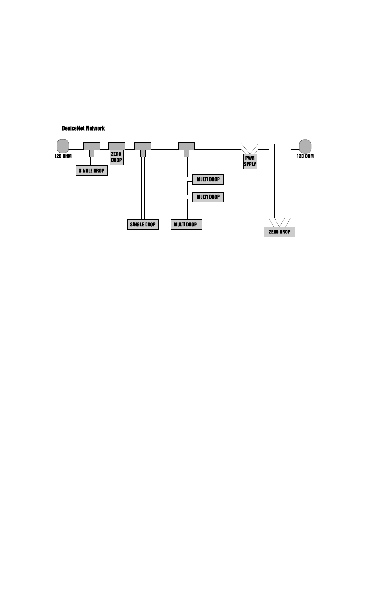
costs. (See Fig. 1-1)
• Trunk Line (thick or thin cable can
be used)
• 120 ohm terminator at each end.
• Drop lines can extend to a maximum
length of 20’ feet.
• Drops may be daisy chained to multi-
ple nodes.
1-5
Page 12
HI 200DNWM MANUAL
FIG. 1-1 DEVICENET NETWORK
• Zero length drops allow direct connection of nodes to the trunk.
• Multiple power supplies can be used
for load distribution and backup.
1-6
Page 13

CHAPTER 2 - SPECIFICATIONS
CHAPTER 2 - SPECIFICATIONS
SCOPE Chapter 2 lists the specifications of the HI
200DNWM weigh module. Specifications
are listed for the standard module and
optional equipment. The specifications listed
are designed to assist in the installation,
operation and troubleshooting of the module.
All service personnel should be familiar with
this chapter before atte mpti ng an installa tion
or repair of the instrument.
Conversion Rate 10 updates per second (When WAVER-
SAVER is turned OFF or set to 1= 55
updates per second)
Resolution 20 bits
Excita ti on Voltage 0-5 VDC
Averages 1 to 255 User Selectable in Single Incre-
ments.
Load Sensors Up to eight (8) 350 ohm Full Wheatstone
Bridge, Strain Gauge Load Sensors/Cells (5
volt excitation) on one vessel. Using more
than 4 load cells requires an external power
supply.
Non-Linearity 0.0015% of Full Scale
Isolation Non Isolated, uses external solid state relays
for set points.
Voltage Input power - Power from DeviceNet Cable
• 24 VDC +/- 1% Network
• 11-25 VDC Node
2-1
Page 14

HI 200 DNWM MANUAL
Temperature Coefficient
Temperature
Less than 0.0005% per degree C for zero and
span.
-10 degrees C to +50 degrees C
Range
Temperature Stor-
-20 degrees to +85 degrees C
age Range
Physical Dimen-
sions
3.80” W x 8.5” L x 1.0” H (96.52 mm W x
215.9 mm L x 25.4 mm H)
Mounting Config •DIN - Rail
• Enclosure Mounting, pc board mounted
to enclosure backplate.
Approvals ODVA Conformance Tested
Display None
DeviceNet Type: Vendor Specific
I/O Slave Messaging: Polling
Profile: Refer to EDS
Baud Rates: 125K, 250K, 500K
Inputs 4 bytes polled in
Outputs 4 bytes polled out
NOTE: The Metric Poll parameter specifies the default for-
mat of the 4 bytes of output data from the weight
scale. A zero value specifies that the default format is
a 32 byte integer value containing net weight in
pounds, with 3 decimal places. A one value specifies
that the default format is a 32 byte integer value containing net weight in kilograms, with 3 decimal
places.
2-2
Page 15

CHAPTER 2 - SPECIFICATIONS
Connectors Phoenix Combicon type with unsealed screw
terminal mate. PC board side-vertical pins.
All connector numbering is from left to right
when looking down on the board with the
connector side of the board facing toward
you.
J1 Load Sensor 8 Pin
8 + EXC (Plus Excitation) + 5VDC
7 + SEN (Plus Sense)
6 + SIG (Plus Signal)
5 - SIG (Minus Signal)
4 - SEN (Minus Sense)
3 - EXC (Minus Excitation)
2 + C2
1 - C2
J2 DeviceNet Interface 5 pin Open
1V - (Black)
2 CAN- (Blue)
3 SHIELD (Bare)
4 CAN+ (White)
5V+ (Red)
J3 Set Point Out Interface 4 Pin
1 RLY 1 (Set Point Output One)
2 GND (Ground)
3 RLY 2 (Set Point Output Two)
4 +5 VDC
2-3
Page 16

HI 200 DNWM MANUAL
Current Draw at
24VDC
Table 1: Current Draw at 24 VDC
# Load
Cells
Milli-Amp Reading
W/Relay
TTL
W/O Relay
TTL
1 167 ma 166 ma
2 174 ma 171 ma
3 179 ma 175 ma
4 189 ma 179 ma
2-4
Page 17

CHAPTER 3 - INSTALLATION
CHAPTER 3 - INSTALLATION
SCOPE Chapter 3 covers unpacking, cabling, inter-
connecting and installing the HI 200DNWM
weigh module. Users and service personnel
should be familiar with the procedures in this
chapter before installing or operating the
weigh module.
Unpacking 1. Before signing the packing slip, inspect
the packing for damage of any kind.
2. Report any damage to the carrier company immediately.
3. Check to see that everything in the package matches the bill of lading. You
should normally have.
4. HI 200DNWM Module
1 HI 200DNWM module with mating
connectors
1 Installation and Operation Manual
NOTE: Electronic Data Sheet Software is available
on our Website www.hardyinst.com
5. HI 200DNWM-DR Module with DIN
Rail Kit
1 HI 200DNWM module with mating
connectors and a DIN Rail adapter.
1 Installation and Operation Manual
NOTE: Electronic Data Sheet Software is available
on our Website www.hardyinst.com
6. HI 200DNWM-SK1 Modules (2 complete modules pre-stacked)
3-1
Page 18

HI 200DNWM MANUAL
2 HI 200DNWM complete weigh mod-
ules pre-stacked.
1 Installation and Operation Manual
NOTE: Electronic Data Sheet Softwar e available on
our Website www.hardyinst.com
7. HI 200DNWM Module with Stacking
Kit (-SK)
1 HI 200DNWM Module with mating
connectors
4 Standoffs
4 Phillips Pan Head Machine Screws
1 Installation and Operation Manual
NOTE: Electronic Data Sheet Software is available
on our Website www.hardyinst.com
8. HI 200DNWM Module Junction Box (SS - Stainless Steel) or (-PS - Painted
Steel)
1 HI 200DNWM Module with mating
connectors mounted in either a stainless steel or painted steel NEMA 4/
4X enclosure.
1 Summing Card mounted in either a
stainless steel or painted steel NEMA
4/4X enclosure.
1 Installation and Operation Manual
NOTE: Electronic Data Sheet Software is available
on our Website www.hardyinst.com
9. If any items are missing, damaged, or
there are any questions, please contact
Hardy Customer Support at:
3-2
Page 19

CHAPTER 3 - INSTALLATION
Hardy Instruments Inc.
3860 Calle Fortunada
San Diego, CA 92123-1825
Phone: (858) 278-4900
FAX: (858) 278-6700
Web Site: http//www.hardyinst.com
E-Mail:
hardysupport@hardyinst.com
10. Record the model number and serial
number of the Weigh Module. Store this
information in a convenient, secure location for reference when contacting Hardy
Instruments Customer Support Department or to buy parts or firmware
upgrades.
Mechanical
Installation
Installing the
Bare Weigh
Module in an
Enclosure
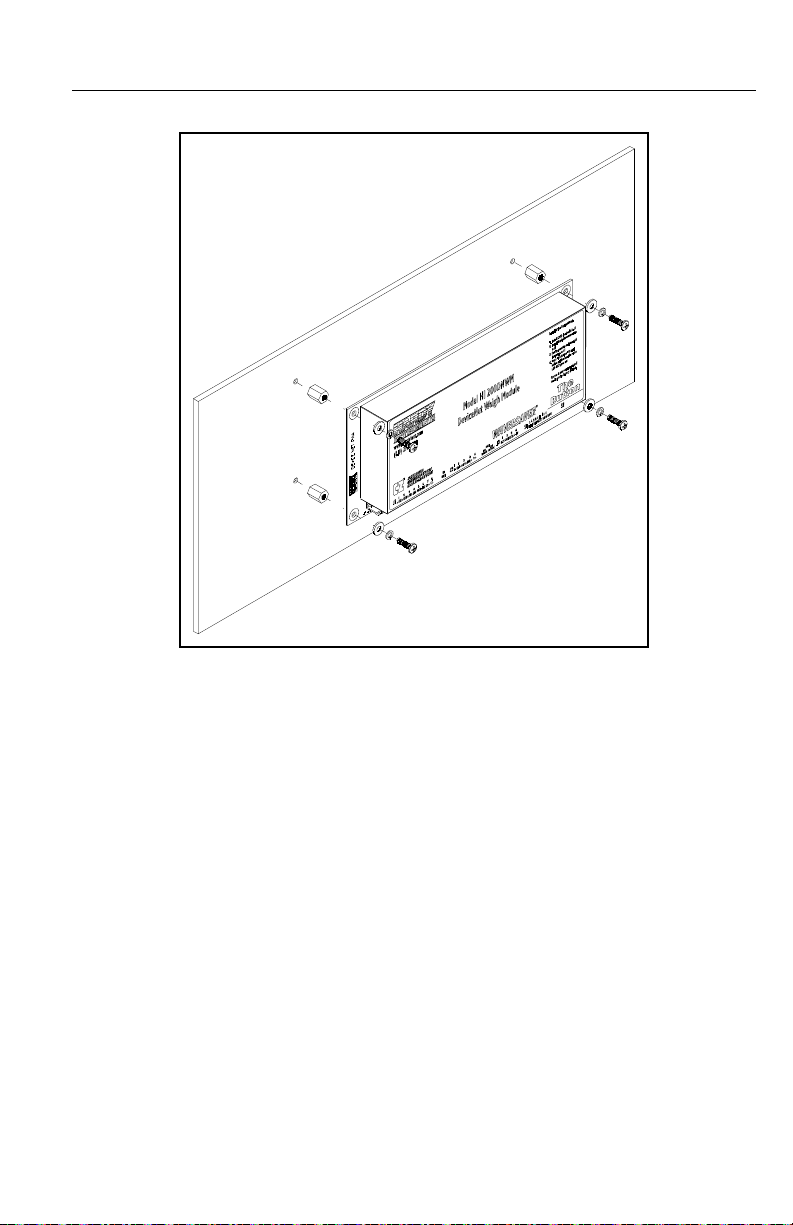
Step 1. Make sure that the Weigh Module
has at least 2 inches clearance
around the entire weigh module.
(See Fig. 3-1)
Step 2. Drill four thru holes or threaded
holes for four 6-32 pan head
machine screws. (See Fig. 3-2)
Step 3. Mount the four standoffs into the
back panel. (See Fig. 3-3)
Step 4. Fasten the weigh module to the
standoffs by installing the four (4)
pan head screws. (See Fig. 3-3)
3-3
Page 20

HI 200DNWM MANUAL
Step 5. Connect the phoenix connectors to
the headers mounted on the weigh
module.
NOTE: Stand offs and fasteners are not included.
NOTE: Make sure that the connectors are seated properly in
the headers.
3-4
FIG. 3-1 2” CLEARANCE AROUND THE MODULE
FIG. 3-2 HOLE DIAGRAM
Page 21
CHAPTER 3 - INSTALLATION
FIG. 3-3 FASTENING MODULE TO BACK PLATE
Installing
Weigh Module
in DIN Rail
Step 1. Take one end piece and one rail
insert. Snap the rail guide insert
into the end piece. Take the other
end piece and install the other rail
guide insert (See Fig. 3-4 & 3-5)
Step 2. Take one of the small rail pieces
and insert the rail pins into the end
piece. (See Fig. 3-6)
Step 3. Take one of the large rail pieces
and insert the rail pins into the
small rail piece. Do this on both
sides. (See Fig. 3-6)
Step 4. Continue installing the rail pieces
until all rail pieces are installed.
(See Fig. 3-7)
3-5
Page 22

HI 200DNWM MANUAL
FIG. 3-4 INSTALLING THE RAIL GUIDE INSERT INTO THE END PIECE
3-6
FIG. 3-5 RAIL GUIDE INSERT IN THE END PIECE
Page 23

CHAPTER 3 - INSTALLATION
FIG. 3-6 INSTALLAT I ON OF THE RAIL PIECES
Step 5. Gently slide the HI 200DNWM
into the assembled DIN Rail until
the board is flush against the other
end piece. (See Fig. 3-7)
Step 6. Take the other assembled end piece
and snap it into the rail pieces. (See
Fig. 3-7)
Step 7. The HI 200DNWM is completely
in the Din Rail assembly ready for
installation. (See Fig. 3-8)
3-7
Page 24

HI 200DNWM MANUAL
FIG. 3-7 INSTALLING THE WEIGH MODULE INTO THE ASSEMBLED
DIN RAIL
FIG. 3-8 WEIGH MODULE INSTALLED IN THE DIN RAIL
NOTE: The Weigh Module can be installed in the DIN Rail
Assembly in either direction.
3-8
Page 25

CHAPTER 3 - INSTALLATION
Installing the
Pre-stacked
Weigh Module
Step 1. Drill four (4) thru holes or threaded
holes for four (4) 6-32 threaded
male 1/4” hex standoffs.
Step 2. Screw four (4) 3/8” long x 1/4”
wide male standoffs into the back
panel.
NOTE: The four (4) 3/8” x 1/4” do not come with the stacki ng
kit.
NOTE: Refer to Paragraph 3.1.1 for clearance and hole
diameter specifications.
Step 3. Place the bottom weigh module
onto the 3/8” standoffs.
Step 4. Fasten the 1.25” x 1/4” threaded
female standoffs that come in the
stacking kit to the 3/8” standoffs.
Step 5. Place the second weigh module
over the 1.25” standoffs aligning
the holes with the threaded holes in
the standoffs.
Step 6. Place the four (4) #6 flat washers
over the mounting holes on the second weigh module.
Step 7. Place the four (4) #6 lock washers
over the four (4) flat washers.
Step 8. Screw the four (4) pan-head
machine screws into the previously
mounted standoffs until the upper
weigh module is fastened securely
to standoffs. (See Fig. 3-9)
3-9
Page 26

HI 200DNWM MANUAL
FIG. 3-9 INSTALLING THE STACKING KIT
Electrical
Installation
Wiring Diagram
Pin Description
for the J1 Load
Sensor 8 Pin
Connector
1-C2
2+C2
3 -EXC (Minus Excitation
4 -SEN (Minus Sense)
5 -SIG (Minus Signal)
6 +SIG (Plus Signal)
7 +SEN (Plus Sense)
8 +EXC (Plus Excitation) +5VDC
NOTE: If the sense lines are not used to measure the actual
excitation voltage at the junction box, an error is
introduced. The error is equal to the percentage of
excitation voltage lost between the instrument and the
junction box. If the excitation voltage at the back of
3-10
Page 27

CHAPTER 3 - INSTALLATION
the instrument is 5 volts and the excitation voltage at
the junction box was 4.9 volts, 0.1 volts was lost due
to cable resistan ce. This loss wi ll caus e a lin ear error
of 1% of applied load in all weight readings. This
error is introduced because the programmed millivolt
per volt data of the load point is multiplied by the
voltage between the sense lines to compute the calibrations curve of the load point. (See Chapter 7,
Paragraph 7.3.2, page 7-3)
Wiring Diagram
Pin Description
for the J2
DeviceNet
Interface 5 Pin
Open
1 V- (Black)
2 CAN- (Blue)
3 Shield (Bare)
4 CAN+ (White)
5V+ (Red)
NOTE: All power for the Weigh Module is received through
the DeviceNet cable. A separate power supply is not
required.
Wiring Diagram
Pin Description
for the J3 Set
Point Out 4 Pin
1 RLY1 (Set Point Output One)
2 GND
3 RLY2 (Set Point Output Two)
4 +5 VDC
Wiring Diagram
for the HI
215JB Junction
Box
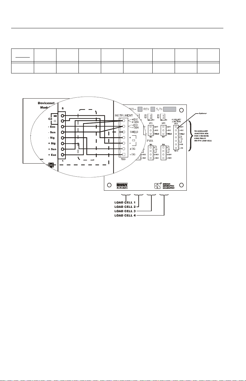
C2 Loadcell
Cable
Connection
(J1)
When connecting the HI 215JB Junction box
using C2 loadcell/point cable (6020-0001)
use the following color code:
3-11
Page 28
HI 200DNWM MANUAL
Model EXC + SEN + SIG + SIG - SEN - EXC - C2 + C2 -
J-BOX RED BLUE GRN WHT BRWN BLK GREY VIO
Table 1: C2 CABLE COLOR CODE/HI 215JB J-BOX
FIG. 3-10 C2 LOAD CELL CONNECTION/HI 215JB JUNCTION BOX
1 Recommended load cell cable, Hardy
Instruments (Prt. #6020-0001)
2 Attach the load shield to the te rminal
block mounted next to the J1 connector on the HI 200DNWM Module.
3 Do not run load cell cable in parallel
with or in the same conduit with
power wiring, relay cables or any
other high energy cables.
4 Remove the factory-installed jumpers
for C2 wire load cell connection.
5 JB summing Card (Part. #0535-0465-
05)
3-12
Page 29

CHAPTER 3 - INSTALLATION
Non-C2
Loadcell
Cable
Connection
(J1)
1 Attach the load cell cable to the ter-
minal block mounted next to the J1
connector on the HI 200DNWM
Module.
2 Factory installed jumpers to remain
in place for 4 wire, non-C2 load cell
connections. (See Fig. 3-11)
3 Do not run load cell cable in parallel
with or in the same conduit with
power wiring, relay cables or any
other high energy cables.
FIG. 3-11 NON C2 LOAD CELL CONNECTION/HI 215JB JUNCTION BOX
3-13
Page 30

HI 200DNWM MANUAL
3-14
Page 31

CHAPTER 4 - CONFIGURATION
CHAPTER 4 - CONFIGURATION
SCOPE Chapter Four consists of all the proce-
dures for configuring the HI 200DNWM
Weigh Module. System configuration
includes only hardware adjustments such
as Jumper and Dip Switch settings. We
recommend that maintenance personnel
be familiar with this chapter before configuring the Weigh Module. Alternative
configuration procedures are not recommended.
Differences in the
Series A and Series B
Modules
Changing from the
Series A to the
Series B Module
Changing from the
Series B to the
Series A Module
The Series B 200 DNWM module uses 4
bytes of input polled data. This requires
each module to use a different .EDS file.
Configuration when using RS NetWorx
for DeviceNet require the new .EDS file.
This adds the 4 bytes of input polled
data. If you want to use the new features
of the module, the 4 bytes of input polled
data need to be mapped into the scanner’s scanlist.
If you do not map the input polled data
into the scanner’s scanlist, the module
will operate as if it were a Series A. No
changes need to be made to any ladder
logic written for the module.
If you change from Series B to the older
module, the configuration when using
RS NetWorx for DeviceNet needs to be
done using the older .EDS file. This will
remove the 4 bytes of input polled data.
These 4 bytes of data must then be
removed from the scanner’s scanlist. All
4-1
Page 32

HI 200DNWM MANUAL
ladder logic written that refers to the 4
bytes of input polled data needs to be
changed and any reference to the output
data also needs to be reviewed and possible modified.
DIP Switch (S1) Configuration
DIP Switch Location
Configuring the
Baud Rate
Configuring the DIP switch sets the following:
1. Baud Rate
2. Node Address
The DIP Switch is located between THE
BUTTON and the J3 Header. (See Fig. 41 & 4-2)
Refer to Table 4-1 to configure the baud
rate. 0 = OFF, 1 = ON (* is the default
setting)
Baud Rate S1-7 S1-8
125 kbps* OFF OFF
250 kbps OFF ON
500 kbps ON OFF
500 kbps ON ON
4-2
Table 4-1: Baud Rate
Page 33

CHAPTER 4 - CONFIGURATION
FIG. 4-1 S1 DIP SWITCH LOCATION
FIG. 4-2 FACTORY DEFAULT DIP SWITCH CONFIGURATION
Configuring the
DeviceNet Node
Refer to Table 4-2 to configure the
DeviceNet Node Address.
Address
4-3
Page 34

HI 200DNWM MANUAL
Address S1-1 S1-2 S1-3 S1-4 S1-5 S1-6
0 OFF OFF OFF OFF OFF OFF
1 OFF OFF OFF OFF OFF ON
2 OFF OFF OFF OFF ON OFF
3OFFOFFOFFOFFONON
“ ““““““
62 ON ON ON ON ON OFF
63 ON ON ON ON ON ON
Table 4-2: DeviceNet Node Addresses
4-4
Page 35

CHAPTER 5 - SETUP
CHAPTER 5 - SETUP
SCOPE All information contained in Chapter 5 per-
tains to software or firmware settings or procedures to prepare the HI 200DNWM weigh
module for calibration and operation. Alternatives to these procedures either explicit or
implied, contained in this section are not recommended. It is very important that the user
and service personnel be familiar with the
procedures contained in this chapter, before
going through the setup procedures.
Saving to Non-Volatile Ram
NOTE: If you have an instrument with version 1.5, please
refer to Devicenet Manual, REV B-6 or earlier for
instructions about Saving to Non-Volatile Ram or
contact Hardy Instruments Customer Service Department.
In version 2.1, the HI 200DNWM does not
automatically save parameters to non-volatile memory. To save parameters to non-volatile RAM, set parameter 38 (Save nonvolatile command) to 1.
This request should be sent after changing
any configuration parameter. It does NOT
need to be sent after altering a command
parameters like TARE or ZERO. It does not
need to be sent after doing a calibration. The
necessary calibration data values are saved
automatically. However, if you change
parameters used during calibration, like
“number of averages”, or “WAVER-
5-1
Page 36

HI 200DNWM MANUAL
SAVER®” for example, the SAVE request
should be sent BEFORE cycling the power.
The non-volatile RAM has a maximum of
5,000,000 writes.
Parameters • Parameter 1 = Metric Poll
True = kgs net False = lbs net
Length in Bytes = 1
NOTE: Default settings are indicated by bold type.
• Parameter 2 = WAVERSAVER® Setting
0 =OFF 1 = 4 Hz, 2 = 2Hz, 3 = 1.0 Hz, 4
= 1/2 Hz
Length in Bytes = 1
NOTE: By selecting OFF (0) or 1 the module increases the
updates per second from 10 to 55.
5-2
• Parameter 3 = Calibration Type
0 = Hard Cal, 1 = C2 Cal, Other = Not
Cal’d (Read Only)
Length in Bytes = 1
• Parameter 4 = Span Weight in Lbs
1 to 2147483647 10000.000
Length in Bytes = 4
• Parameter 5 = Averages
0 to 255 10
Length in Bytes = 1
• Parameter 6 = Set Point One Mode
bit 7 = On/Off bit 1 = Low/High
bit 0 = Net/Gross
Length in Bytes = 1
Page 37

CHAPTER 5 - SETUP
• Parameter 7 = Set Point One Lbs Value
-2147483648 to 2147483647
10000.000
Length in Bytes = 4
• Parameter 8 = Set Point One Deadband
in Lbs
0 to 2147483647 0.100
Length in Bytes = 4
• Parameter 9 = Set Point One Preact in
Lbs
0.00 to 2147483.647
Length in Bytes = 4
• Parameter 10 = Set Point Two Type
bit 7 = On/Off
bit 1 = Low/High
bit 0 = Net/Gross
Length in Bytes = 1
• Parameter 11 = Set Point Two Lbs Value
-2147483648 to 2147483647
100000.000
Length in Bytes = 4
• Parameter 12 = Set Point Two Deadband
in Lbs
0 to 2147483.647 0.100
Length in Bytes = 4
• Parameter 13 = Set Point Two Preact in
Lbs
0 to 2147483647
Length in Bytes = 4
5-3
Page 38

HI 200DNWM MANUAL
• Parameter 14 = Number of C2® Chips
Found
0 to 8 (Read Only)
Length in Bytes = 1
• Parameter 15 = Net Weight in Lbs
Read Only
Length in Bytes = 4
• Parameter 16 = Gross Weight in Lbs
Read Only
Length in Bytes = 4
• Parameter 17 = Tare Weight in Lbs
-999999 - 999999 0.00
Length in Bytes = 4
• Parameter 18 = Tare Command
0 to 1 (Set to True to Complete Command)
Length in Bytes = 1
5-4
• Parameter 19 = Zero Command
0 to 1 (Set to True to Complete Command)
Length in Bytes = 1
• Parameter 20 = Calibrate Low Command
0 to 1 (Set to True to Complete Command)
Length in Bytes = 1
• Parameter 21 = Calibrate High Command
0 to 1 (Set to True to Complete Command)
Length in Bytes = 1
Page 39

CHAPTER 5 - SETUP
• Parameter 22 = Calibrate using C2®
0 to 1 (Set to True to Complete Command)
Length in Bytes = 1
• Parameter 23 = Span Weight in Kgs
0.000 to 2147483.647 0.045
Length in Bytes = 4
• Parameter 24 = Set Point One Kgs Value
Read Only
Length in Bytes = 4
• Parameter 25 = Set Point One Deadband
in Kgs
0.00 to 2147483.647 0.045
Length in Bytes = 4
• Parameter 26 = Set Point One Preact in
Kgs
0 to 2147483.647
Length in Bytes = 4
• Parameter 27 = Set Point Two Kgs Value
-2147483.648 to 2147483.647
4535.923
Length in Bytes = 4
• Parameter 28 = Set Point Two Deadband
in Kgs
0 to 2147483.647 0.045
Length in Bytes = 4
• Parameters 29 = Set Point Two Preact in
Kgs
0 to 2147483.647
Length in Bytes = 4
5-5
Page 40

HI 200DNWM MANUAL
• Parameter 30 = Net Weight in Kgs
Read Only
Length in Bytes = 4
• Parameter 31 = Gross Weight in Kgs
Read Only
Length in Bytes = 4
• Parameter 32 = Tare Weight in Kgs
-999999 - 999999 0.00
Length in Bytes = 4
• Parameter 33 = Relay Outputs
Length in Bytes = 1
• Parameter 34 = A/D Counts
Length in Bytes = 4
• Parameter 35 = Calibration Low Weight
in Lbs.
Length in Bytes = 4
5-6
• Parameter 36 = Calibration Low Weight
in Kgs.
Length in Bytes = 4
The “Calibration Low Weight” parameter specifies the w eight on the scal e when
the low step of a calibration is done in
Traditional Calibration and is the Reference Point for C2 Calibration.
• Parameter 37 = Weight Multiplier
Length in Bytes = 4
This integer parameter can be set to 1,
10, 100, etc. to allow the user to select
Page 41

CHAPTER 5 - SETUP
the number of decimal places in the 32
bit integer weight outputs. The value 0
causes these weight outputs to be in
floating point format.
NOTE: This applies ONLY to the weights as viewed through
the I/O (Command) interface. The explicit message
interface continues to use 3 decimal place 32 bit integer format only.
• Parameter 38 = Write non-volatile com-
mand.
Length in Bytes = 1
Setting this parameter to 1 will cause a
save to non-volatile memory. Calibration data is saved to non-volatile memory
automatically. Other parameters must be
saved using this command.
Command
Interface
• Parameter 39 = Parameter high word.
Length in Bytes = 2
This parameter is used in the command
interface as described below:
The Command Interface allows easy access
to all parameters without using explicit messages.
The HI 200DNWM version 2.1 produces 4
bytes of polled output data and consumes 4
bytes of polled input data. The 4 bytes of
input data can be used to set parameters in
the module and to specify what data should
be placed in the 4 bytes of output data.
5-7
Page 42

HI 200DNWM MANUAL
Format of
Commands (4
byte input
data)
Byte 0 Parameter value, least significant byte. (Used by
the WRITE command only.
Byte 1 Parameter value, second l ea s t sig ni fic ant byte.
(Used by the WRITE command only.)
Byte 2 Parameter number. The parameter number is the
Byte 3 (Command byte): 0=READ command. 1 =
instance of the par ameter object. These are li s ted
in the HI 200DNWM manual .
WRITE command
Most of the HI 200DNWM’s parameters are
only 1 byte long, making it possible to write
them with a single command. There are also
some 4 byte parameters. To write one of
them:
Step 1. First write the 2 most significant
bytes, using a WRITE command as
described above, with 0x27 in the
parameter number field.
Step 2. Write the least significant bytes
using normal parameter numbers.
The module will combine the value
written to parameter 0x27 with the
least significant bytes to produce
the value written to the 4 byte
parameter.
5-8
The 4 bytes written to the output table are as
follows:
• If the Command byte of the input data is
0 (READ), the data is the value of the
specified parameter, least significant byte
first.
Page 43

CHAPTER 5 - SETUP
• If the specified parameter is an invalid
number (0 for example: there is no
parameter number 0), the data is net
weight, with units as determined by the
METRIC POLL parameter.
• If the Command byte of the input data is
non-zero (WRITE), the output data
echoes the input data.
Examples
Using the
Command
Interface
Reading Gross Weight in the polled output
data.
1. First word (2 least significant bytes) of
the input data is not used. Ignore.
2. Lower byte of second word is the param-
eter number. Gross weight in lbs is
parameter #16.
3. Upper byte of second word set is “0”
indicating read.
This causes the unit to output the Gross
weight in lbs to the output polled data area.
Resolution and data type would depend on
the Weight Multiplier setting.
Writing new value to number of averages.
1. First byte of first word on the input data
is the new valued wanted.
2. Upper byte of first word should be 0 and
is not used.
3. Lower byte of second word is the param-
eter number. Averages is parameter #5.
4. Upper byte of second word is set to “1”
to indicate write.
This causes the unit to write the value in the
first byte of the first word to the Averages
5-9
Page 44

HI 200DNWM MANUAL
Setpoints
parameter. During the execution of the command, the output polled data reflects the
input polled data.
About SetPoints
Dead Band
Limits
The set point value is the target weight or
level in either net or gross weight units
The dead band value can be set as a High or
Low value. It is used to deactivate the set
point.
For example:
If a set point value was 1000 pounds and the
dead band was set to 5 pounds, the relay
would close at a 1000 pounds but not open
until the weight dropped to 995 pounds. This
is used if a set point is a high trip limit. A
High dead band would be used for a low trip
limit. Examples are show for Low and High
Trip Limits in Fig. 5-2.
5-10
Page 45

CHAPTER 5 - SETUP
FIG. 5-1 LOW AND HIGH PREACT TRIP LIMITS
Three General
Rules for Set
Points
1. Set Points activate at the set point plus
the preact.
2. Set Points deactivate at the set point plus
the deadband.
3. The deaband should be numerically
larger than the preact.
Preact Limits 1. The preact value is the number of units
below or above the set point at which the
relay will trip.
2. The preact value is used as an “in-flight”
compensation value when filling a vessel. If set to zero, there will be no compensation.
Entering Set
Points
Change the Set Point Parameters in accordance with the DeviceNet Manager you are
5-11
Page 46

HI 200DNWM MANUAL
Setpoint Mode
Parameters
using. Be sure to read the DeviceNet Manager instructions first before setting.
About
Setpoint
Mode
Parameter
Entering
Setpoint
Mode
Parameters
The Setpoint mode parameter is a bit
encoded byte that affects the behavior of the
setpoint.
Bit Description
Bit 7 Setpoint On/Off. Set to 1 to activate the setpoint, set
to 0 to disable it.
Bit 6 Set to 1 to output 0 vol ts (Force Relay Off)
Bit 5 Set to 1 to output 5 vol ts (Force Relay On)
Bit 1 Set to 0 for a gain in weight setpoint, set to 1 for a loss
in weight setpoint.
Bit 0 Set to 1 for a setpoint based on Net weight, or to 0 for
a setpoint based on gross weight.
5-12
Page 47

CHAPTER 6 - CALIBRATION
CHAPTER 6 - CALIBRATION
SCOPE Chapter 6 pertains to the calibration pro-
cedures for the HI 200DNWM weigh
module. Alternatives to any procedures
either implied or explicitly contained in
this chapter are not recommended. In
order for the weigh module to work
properly, it must be calibrated prior to
operation. All calibration should be recalibrated periodically, or when not in
use for extended periods of time. Be sure
to follow all the procedures completely
to insure that the weights read by the
module are accurate. It is very important
that the user and service personnel be
familiar with the procedures contained in
this chapter, before installing or operating the HI 200DNWM weigh module.
Pre-Calibration Procedures
Step 1. Check to see if the load cell/
sensor/points are properly
installed. Refer to your load
cell I&M manual for proper
installation instructions.
Step 2. Check to be sure that the con-
nectors are installed firmly in
the weigh module headers.
NOTE: You need to go thr oug h the p re-calibration pro ce-
dures before each calibration, regardless of the
type of calibration you are performing.
C2® Calibration (The
Button)
Step 1. The Module LED must be
green in color . If it is not do not
try to calibrate the instrument.
Contact Hardy Instruments
6-1
Page 48
HI 200DNWM MANUAL
Customer Support for assistance.
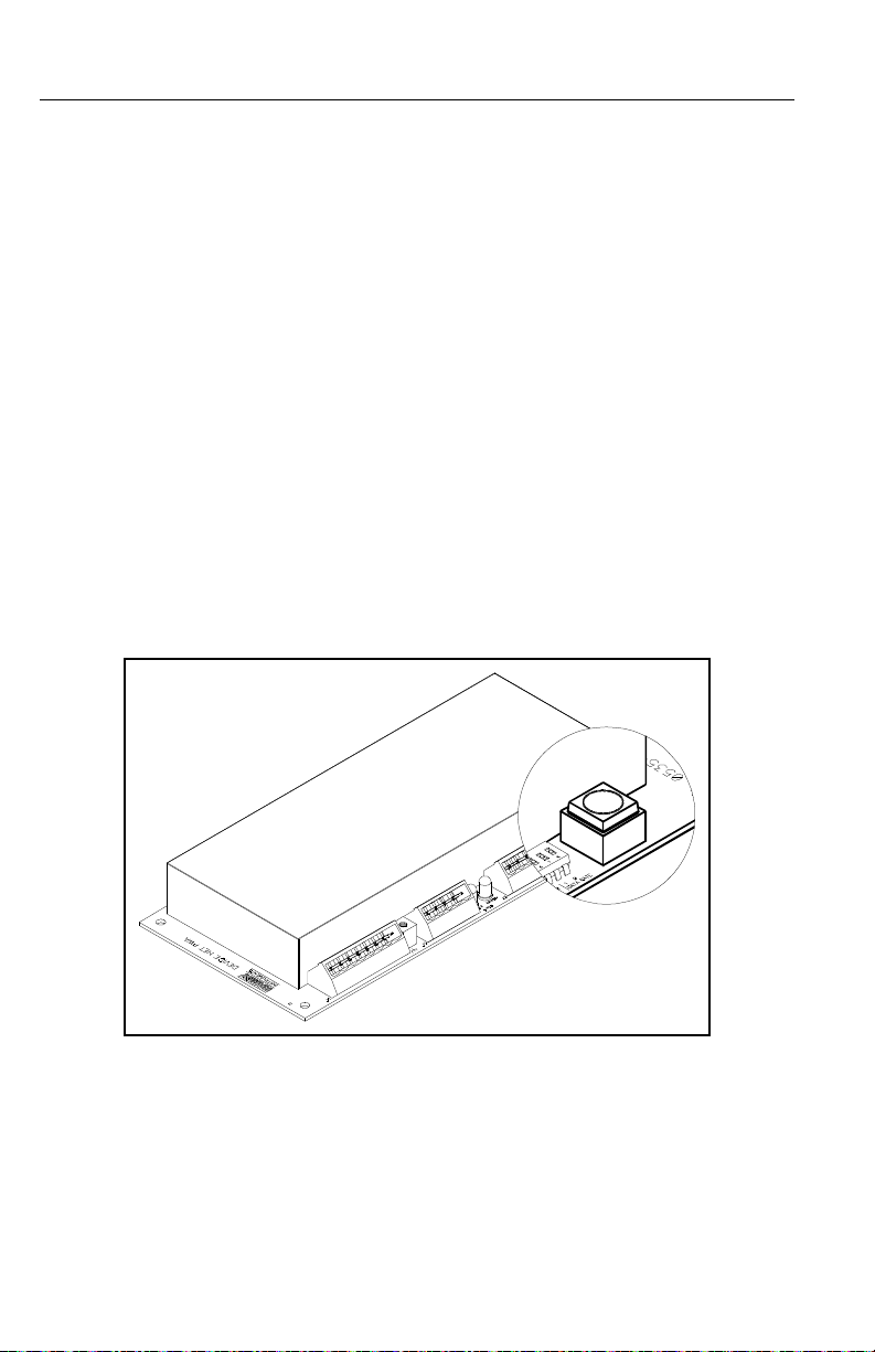
Step 2. Press the RED BUTTON on the
weigh module printed circuit
board and hold the button down
until the Module Status LED
goes off. (See Fig. 6-1)
NOTE: This could take up to 2 seconds.
Step 3. When the Module Status LED
comes back on. Release the
RED BUTTON. The weigh
module system is calibrated.
Step 4. If the LED does not come back
on contact Hardy Customer
Support for assistance.
FIG. 6-1 THE RED BUTTON
C2® Calibration from
RS NetWorx
6-2
®
Step 1. On the PC open RS NetWorx
®
Step 2. Browse the Network.
Step 3. Double click on the Node Icon
of the weigh module you want
to calibrate. For example: Node
Page 49

CHAPTER 6 - CALIBRATION
36. The DeviceNet Weigh
Module Dialog Box appears.
Step 4. Click on the Parameter tab. The
Parameter List appears with the
information for the weigh mod-
ule at address 36.
Step 5. Click on Cal LO.
Step 6. Enter the Cal LO value.
Step 7. Click on the Apply button.
Step 8. Click on Yes.
Step 9. Click on C2 Cal Cmd.
Step 10. Set the C2 Cal Cmd to “1”.
Step 11. Click on the Apply button.
Step 12. Click on Yes.
Step 13. Click on Cmd Save non-vol.
Step 14. Set the Cmd Save non-vol to
“1”.
Step 15. Click on the Apply button.
Step 16. Click on Yes.
Step 17. The calibration is complete.
NOTE: Requires C2® load sensors or load points.
NOTE: RS NetWorx® is a registered trademark of Rock-
well Automation.
Test Weight Calibration from RS Net-
®
Worx
Step 1. On the PC open RS NetWorx
Step 2. Browse the Network.
Step 3. Double click on the Node Icon
®
of the weigh module you want
to calibrate. For example: Node
36. The DeviceNet Weigh
Module Dialog Box appears.
Step 4. Click on the Parameter tab. The
Parameter List appears with the
information for the weigh mod-
ule at address 36.
Step 5. Click on Span Weight.
6-3
Page 50

HI 200DNWM MANUAL
Step 6. Enter the Span Weight Value.
Step 7. Click on Cal LO.
Step 8. Enter the Cal LO weight.
Step 9. Click on Cal LO command.
Step 10. Set the Cal LO to “1”.
Step 11. Click on the Apply button.
Step 12. Click on Yes.
Step 13. Place the test weight on the
scale.
Step 14. Click on Cal HI command.
Step 15. Set the Cal HI command to “1”
Step 16. Click on the Apply button.
Step 17. Click on Yes.
Step 18. Click on Cmd Save non-vol.
Step 19. Set the Cmd Save non-vol to
“1”.
Step 20. Click on the Apply button.
Step 21. Click on Yes.
Step 22. The calibration is complete.
6-4
Page 51

CHAPTER 7 - OPERATION
CHAPTER 7 - OPERATION
SCOPE All information contained in Chapter 7 per-
tains to the operation of the HI 200DNWM
weigh module. We recommend that the processes and procedures contained in this
chapter be followed to insure that the module
give the user maximum quality performance.
It is very important that the user be familiar
with this chapter before operating the weigh
module.
Operating
Capabilities
Explicit Message
Request
Parameters
The HI 200DNWM can do the following or
can be used in the following operations:
1. Monitor Weight Readings
2. Filling
3. Dispensing
4. Check Weighing
5. Batching
The procedures for sending the Explicit
Message Requests are unique to each PLC
and the user needs to refer to their PLC users
guide, PLC DeviceNet Scanner section for
instructions. The HI 200DNWM needs the
following information to respond to an
Explicit Message Request:
•SERVICE:
The HI200DNWM WEIGH
MODULE can process the
“Get_Attribute_Single” (14) and
“Set_Attribute_Single” (16).
• CLASS: The Device Net parameter
Class is 15.
• INSTANCE: The HI 200DNWM
WEIGH MODULE parameter number
7-1
Page 52

HI 200DNWM MANUAL
can be found in the HI 200DNWM
WEIGH MODULE I&O manual.
• ATTRIBUTE: The parameter value
attribute number is 1.
•DATA: (varies)
NOTE: Data length can vary, be sure to enter the correct
length (size) of data or problems will occur.
NOTE: Order of bytes must be least significant first.
Monitoring Weight
Readings from RS
NetWorx
Step 1. On the PC open RS NetWorx.
Step 2. Browse the Network.
Step 3. Double click on the Node Icon of
the weigh module you want to
monitor. For example: Node 36.
The DeviceNet Weigh Module Dia-
log Box appears for Node 36.
Step 4. Click on the Parameters Tab.
Step 5. All the parameters including the
weights are displayed.
Step 6. The NET, GROSS, and TARE
weights are now being monitored.
NOTE: The HI 200DNWM can be used for Batching, Filling,
Dispensing, and Check Weighing applications.
Network Status
(DS1)
STATE LED INDICATION
NOT POWERED/
NOT ON LINE
OFF DEVICE IS NOT ON LINE
1. NO POWER APPLIED
2. Dup_MAC_ID TEST NOT COMPLETE
OPERATIONAL
AND ON-LINE
7-2
GREEN ON LINE NORMAL CONDITION WITH CONNECTIONS
ESTABLISHED.
Table 7-1: NETWORK STATUS (DS1)
Page 53

CHAPTER 7 - OPERATION
STATE LED INDICATION
OPERATION
AND ON LINE
NOT CONNECTED
CRITICAL
FAULT OR LINK
FAILURE
FLASHING
GREEN
RED UNRECOVERABLE FAULT (MAY NEED REPLACING)
ON LINE NORMAL CONDITION NO CONNECTIONS
Dup_MAC_ID PASSED & ON LINE, NO CONNECTIONS
TO OTHER NODES.
FAI LED COMMUIC ATIONS (DUPLICATE Mac ID OR BUS
OFF)
Table 7-1: NETWORK STATUS (DS1)
Module Status
(DS2)
STATE LED INDICATION
NOT POWERED/
NOT ON LINE
OPERATIONAL GREEN NORMAL CONDITION
MINOR FAULT
AND/OR CONNECTION TIMEOUT
CRITICAL
FAULT OR LINK
FAILURE
OFF DEVICE IS NOT ON LINE
FLASHING
RED
RED UNRECOVERABLE FAULT (Board MAY NEED REPLAC-
1. NO POWER APPLIED
RECOVERABLE FAULT A/D ERROR, USUALLY
CAUSED BY BAD CONNECTION TO LOAD CELLS
LOAD CELL OUT OF RANGE. SENSE LINES MUST BE
INSTALLED. (See Chapter 3, Page 3-10 for more information)
ING)
FAILURE IN A-D.
Table 7-2: MODULE STATUS (DS2)
7-3
Page 54

HI 200DNWM MANUAL
7-4
Page 55

CHAPTER 8 - TROUBLESHOOTING
CHAPTER 8 - TROUBLESHOOTING
SCOPE All the information in Chapter 8 pertains to
the troubleshooting and resolution of operating problems that may occur. All maintenance personnel and users should be familiar
with Chapter 8 before attempting to repair
the HI 200DNWM.
Module LED does
not Come Back on
When Performing
Calibration with
The Button
Module LED is
Flashing Red
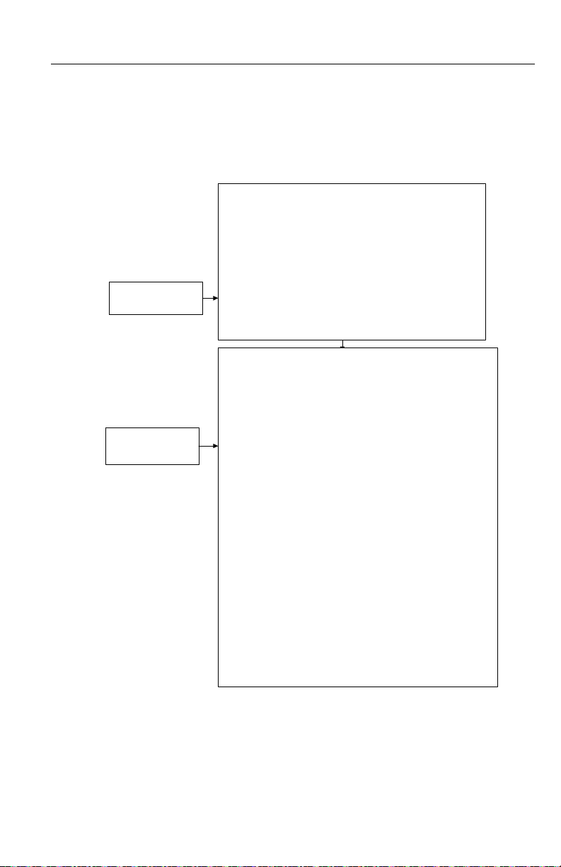
Mechanical
Inspection
If the Module LED does not come back on
when performing The Button (C2 Calibra-
tion) it indicates a hardware problem. Contact Hardy Customer Support for assistance.
Solution: Check all the connections to be
sure they are securely fastened. Reinstall if
any appear to be loose.
See Fig. 8-1
8-1
Page 56

HI 200DNWM MANUAL
All pipes and conduits
flexible?
Mechanically isolated
from ladders and
connecting structures?
1) Floors or structure does not interact.
2) Local traffic does not interact
3) Protected from forklifts and adjacent processing equipment
Are the load cells properly
mounted?
Are Check rods installed
to dampen vessel
movement?
1) Protects the load cells from overload and impact forces
2) Limits the movement of the vessel
3) Rods must be loose and not interacting with the vessel.
Are cables routed
properly?
1) Product, tools and production aids are off the vessel.
2) No workers are physically on the scale
3) Must protect equipment from environmental damage
4) Insure openings are sealed to keep water and environmental
contaminates from damaging:
(a) Instrument cabinet or enclosure
(b) Summing card
(c) Load Cells
(d) Conduit runs
(e) covers are properly installed
1) Keep flexures on the horizontal
2) Vertical flexures should be avoided
3) Do not use flexures to correct for misaligned piping
4) Do not use hose flexures to make right angle bends
5) Non-flexed piping should have an unsupported
horizontal run using a ratio of 36 times it's diameter.
6) Pipe flexure lengths should be a ratio of 6 times it's diameter
7) Feed and discharge piping flexed
8) Are the flex joints on the correct side of the valve ?
(a) You weigh the output valve, not the input valve
(b) Does the weigh scale see all the product to be
weighed?
(c) If the product applies a force to a valve or pipe, that .
pipe or valve must be included in the weigh vessel.
(d) Proper positioning of the flexures are key.
(e) Your vessel must seem to float.
1) Separate conduit for low and high voltage cables.
2) Do not bundle Low voltage with High voltage cables
3) Maintain at least 3 inches of seperation.
4) Maintain 14"seperation from magnetic fields and 440 vac.
5) Cables are in conduit or tied up and protected from damage.
1) Level, solid mounting base
2) The load cell is mounted right side up.
3) All load cell bolts installed using anti-seize compounds.
4) Mechanically aligned to compensate for expansion and
contraction.
Housekeeping
8-2
FIG. 8-1 MECHANICAL INSPECTION
Page 57
CHAPTER 8 - TROUBLESHOOTING
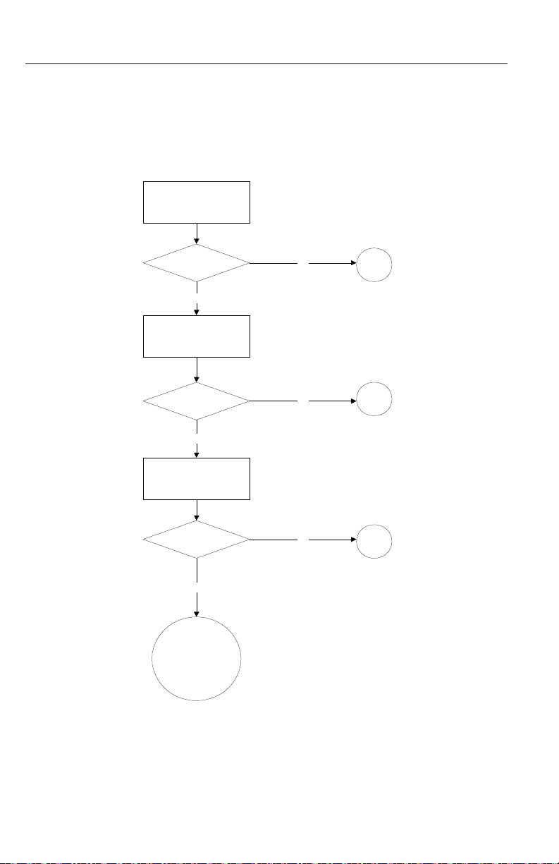
Load cell wiring is
complete and correct?
1) Does the mV signal i ncrease in a positive direction.
2) If you receive a negative result s, check if load cell is
mounted correctly.
a) The arrow goes with the direction of force.
b) If there isn't an arrow, you must manually verify the
correct direction. A negative reading indicates the
load cell is upside down.
c) Load cells in tension will not reflect a negative
reading if install upside down. If upsi de dow n, only
the force applied by the cable would be included in
the weight readings.
d) If you are still receiving a negative signal, verify
load cell wire color code
Multiple load cells?
MAP the mV reading.
Balance the load
1) Verify a positive reading f rom each l oad cell, using a
volt meter.
2) Record the mV reading and compare each corner for
proper load sharing.
a) Proper load sharing should see only a di fference
of +/- .5 mV.
b) Larger differences due t o m otors and piping,
should not exceed +/- 2 mV.
c) If there isn't any motors, valves, or piping to
explain the mV difference, adjust t he corners and
balance the mV readings.
d) Use shims, or if equipped adjusting bolts on the
load cell mounting hardware.
e) Drawing a load cell map will help determine the
correct leg to adjust and in which direction.
Three load cells balance like a three legged chair.
1) Using a sprit level, verify the vessel is vertically and
horizontally correct.
2) Verify if any height change will effect the attitude of adjacent
vessels or piping.
3) Adjust each legs to dynami cal l y m atch mV outputs
4) Verify the mV readings and physical l evel when complete.
Four load cells or more present a challenge.
1) Use volt meter to determine the sum of the load cell signals
and your target mV setting for each load cell.
2) Read the output of i ndi vi dual load cells.
3) Adjust the load cell with the lowest reading to dynamically
match the target mV readings obtained in step 1.
4) Read the mV readings from each load cell to verify a proper
correction.
5) Repeat step 3 and 4 to achieve a proper load sharing vessel .
6) Verify the mV readings and vessel level when complete.
Load Sharing and
Load Sensor
Checkout
See Figure 8-2
FIG. 8-2 LOAD SHARING AND LOAD SENSOR CHECKOUT
8-3
Page 58
HI 200DNWM MANUAL
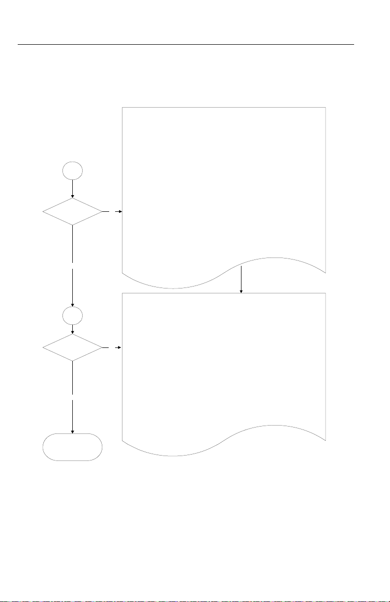
Check for
Electrical Stability
OK ?
Contact Hardy
Instruments
Customer Support
Check for
Mechanical Stability
OK ?
Yes
Check Configuration
settings for
Stability
No
OK ?
Yes
Yes
B1
B2
B3
No
No
Guidelines for
Instabilities on
Formerly Operating Systems
See Figure 8-3
FIG. 8-3 GUIDELINES FOR INSTABILITIES ON FORMERLY OPERAT-
8-4
ING SYSTEMS
Page 59

CHAPTER 8 - TROUBLESHOOTING
ElectricalB1
Physical Grounding
All common equipment share a common ground point.
Keep the ground cable length to earth ground as short as possible.
Install a new ground rod if the cable length is excessive.
Cable -
Cuts or breaks in the loadcell cable insulation allow moisture to wick into the cable
and loadpoints. This can setup stray capacitance charges and allow ground currents
to exist. This could create a highly intermittent situation.
Loadcells
Ground straps must be installed to provide a direct discharge path to ground around
the loadpoints.
Vessel, Fill and discharge piping
Ground all to a common point to eliminate electrical differences in potential, and
static build-up.
Cable Routing
Seperate high voltage sources and cables from low voltage signal cables.
Stay a minimum of 14 inches from Magnetic fields and SCR controls.
Avoid parallel high voltage and signal cable runs.
Cable Shielding -
Ground low voltage cable shields only at the controller end.
Grounding both cable ends will produce ground currents.
Verify, with an ohm meter, the shield is only grounded at the weight controller.
Disconnect the shield at the controller and check for an open circuit between ground
and shield. Reconnect the shield to ground and confirm a proper ground path from
the Junction box to the controller.
Verify the shield is not connect to ground at the Junction Box.
Loadcell cable shields only pass thru the Junction Boxes and are not connected to
ground at that point.
B1.1
B1.3
B1.2
B1.4
B1.5
B1.6
GOTO
B
Electrical See Figure 8-4
FIG. 8-4 GUIDELINES FOR INSTABILITIES ON FORMERLY OPERAT-
ING SYSTEMS - ELECTRICAL
8-5
Page 60
HI 200DNWM MANUAL
Mechanical Stability
Vessel -
When inspecting a vessel keep in mind, the Center of Gravity (COG) should be
low and centered equally over all the load cells.
Insure the load is directly over or under the load point to avoid side-loading.
Insure there isn't any side loading from piping or ext er nal f or c es .
Install flexures on all piping to insure a free float ing v es sel.
Insure the vessel and loadcell mounts are mechanically stable and fixed.
Large changes in individual Loadcells indicate a shift in COG orfaulty Loadcells.
Piping and motors will effect t he indiv idual loadc ell r eadings.
Allow for a higher reading on Loadcells that support motor s and piping.
Insure pneumatic lines are not applying pressure to t he v ess el when ener giz ed.
Use check (stay) rods to minimize vessel movement.
Insure the check rods are loose and not interact ing with the vessel.
Power down all vibration, vacuum and pressurization equipment dur ing the test
process.
B2
Configuration settings
Incorrect Waversaver settings
can cause unstable weight readings
Adjust to the lowest WS setting that gives you a stable reading.
Higher frequencies with low amplitude vibrations; - Use WS settings 2 or 3
Low frequency with high amplitude vibrations; - Use W S se t t ing 0 or 1.
Repeatability -
Divide the total loadcell capacity, including decimal point s , by load cell divisions,
1,000 to 10,000.
(expected stable weight reading).
Resolution -
Divide the total loadcell capacity, including decimal point s , by 30,000.
(The amount you can expect to see, but not nec es s arily s t able)
B3
Stable ?
No
Stable ?
No
Yes
Yes
Contact
Hardy Instruments
Customer Support
Mechanical St a b ility and Configuration Settings
See Figure 8-5
FIG. 8-5 MECHANICAL STABILITY AND CONFIGURATION SETTINGS
8-6
Page 61

Index
Index
A
About Hardy Manuals
About Setpoint Mode Paramete 5-12
About SetPoints 5-10
Approvals 2-2
ATTRIBUTE 7-2
Averages 2-1
B
Batching
Baud Rate 4-2
C
C2 Loadcell Cable Connection
C2® Calibration 1-4
C2® Calibration (The Button) 6-1
C2® Calibration from a Personal
Computer
C2® Second Generation Calibration
7-1
6-2
1-1
3-11
1-4
Calibration Type 1-3
Check Weighing 7-1
CLASS 7-1
Command Interface 5-7
Configuring the Baud Rate 4-2
Configuring the DeviceNet Node Address
4-3
Connectors 2-3
Conversion Rate 2-1
Current Draw at 24VDC 2-4
Customer Support Department 1-1
D
Daisy Chained
DATA 7-2
Deactivate the Set Point 5-10
Dead Band Limits 5-10
DeviceNet 2-2
DeviceNet Cable 2-1
DeviceNet Manager 6-2, 6-3
DeviceNet Node Address 4-3
1-5
DeviceNet™ Network 1-2
DeviceNet™. Configuration 1-2
DIN Rail Adapter 3-1
DIN Rail Kit 3-1
DIP Switch (S1) Configuration 4-2
DIP Switch Location 4-2
Dispensing 7-1
Display 2-2
Drop Lines 1-5
Drops 1-5
E
Electrica
Electrical Installation 3-10
Electronic Data Sheet Software 3-2
Entering Set Points 5-11
Entering Setpoint Mode Parameters
8-5
5-12
Excitation Voltage 2-1
Explicit Message Request Parameters
7-1
F
Filling
7-1
Format of Commands (4 by te input data)
5-8
G
Global Industry-Standard Communication Network
Guidelines for Instabilities on Formerly Operating Systems
H
HI 200DNWM Module Junction Box
1-4
8-4
3-2
HI 200DNWM Module with Stacking
Kit
3-2
HI 200DNWM- SK1 Modules 3-2
High dead band 5-10
high trip limit 5-10
Page 62

HI 200DNWM MANUAL
I
I/O block
I/O module 1-5
Input power 2-1
Inputs 2-2
Installing the Bare Weigh Module in
an Enclosure
Installing the Pre-stacked Weigh Module
Installing Weigh Module in DIN Rail
1-5
3-3
3-9
3-5
INSTANCE 7-1
J
J1
2-3
J2 2-3
J3 2-3
L
load cell I&M manual
Load Sensors 2-1
Load Sharing and Load Sensor Checkout
8-3
Low and High Trip Limits 5-10
low trip limit 5-10
M
Mechanical Installation
Mechanical Stability and Configuration Settings
Metric Poll 2-2
Module LED does not Come Back on
When Performing Calibration with
The Button
Module LED is Flashing Red 8-1
Module Status (DS2) 7-3
Module Status LED 6-2
Monitor Weight Readings 7-1
Monitoring Weight Readings 7-2
Mounting Config 2-2
Multiple power supplies 1-6
8-6
8-1
6-1
3-3
N
Network Sta tus (DS1)
Node Icon 6-2, 6-3
Non-C2 Loadcell Cable Connection
(J1)
3-13
Non-Linearity 2-1
Non-Volatile RAM 5-1
O
Operating Capabilities
Outputs 2-2
P
Parameters
Phoenix Combicon 2-3
Physical Dime nsions 2-2
Physical Layer 1-5
Preact Limits 5-11
Pre-Calibration Procedures 6-1
R
Red Button
Resolution 2-1
S
Saving to Non-Volatile Ram
Scale System 1-4
Set Point Values 1-3
Setpoint Mode Parameters 5-12
Setpoints 5-10
Six (6) Conductor Load Cell Cable 3-
5-2
6-2
7-2
7-1
5-1
13
Span Weight 1-3
Standoffs 1-2
T
Tare Weights
Temperature Coefficient 2-2
Temperature Range 2-2
Temperature Storage Range 2-2
Test Weight Calibration Procedures
1-2
6-3
THE BUTTON 1-4, 4-2
Page 63

The Button 1-4
Three General Rules for Set Points 5-
11
Trunk Line 1-5
U
Unpacking
Unused Wires 3-14
V
Vendor Specific
Voltage 2-1
W
WAVERSAVER
Weigh Module 1-2
What is DeviceNet®? 1-4
Wiring Diagram for the HI 215JB
Junction Box
Wiring Diagram for the J2 DeviceNet
Interface 5 Pin Open
Wiring Dia gram for the J3 Set Point
Out 4 Pin
3-1
2-2
1-3
3-11
3-11
3-11
Index
Z
Zero and Tare commands
Zero Length Drops 1-6
1-2
 Loading...