

Page 1

HI 1769-WS & HI 1769-2WS
WEIGH SCALE MODULE
OPERATION AND INSTALLATION
MANUAL
Corporate Headquarters
9440 Carroll Park Drive
San Diego, CA 92121
Phone: (858) 278-2900
FAX: (858) 278-6700
Web-Site: http://www.hardysolutions.com
Hardy Process Solutions Document Number: 0596-0282-01 Rev T
Copyright 2011-2013 Hardy Process Solutions, All Rights Reserved. Printed in the U.S.A. (941028)
Page 2
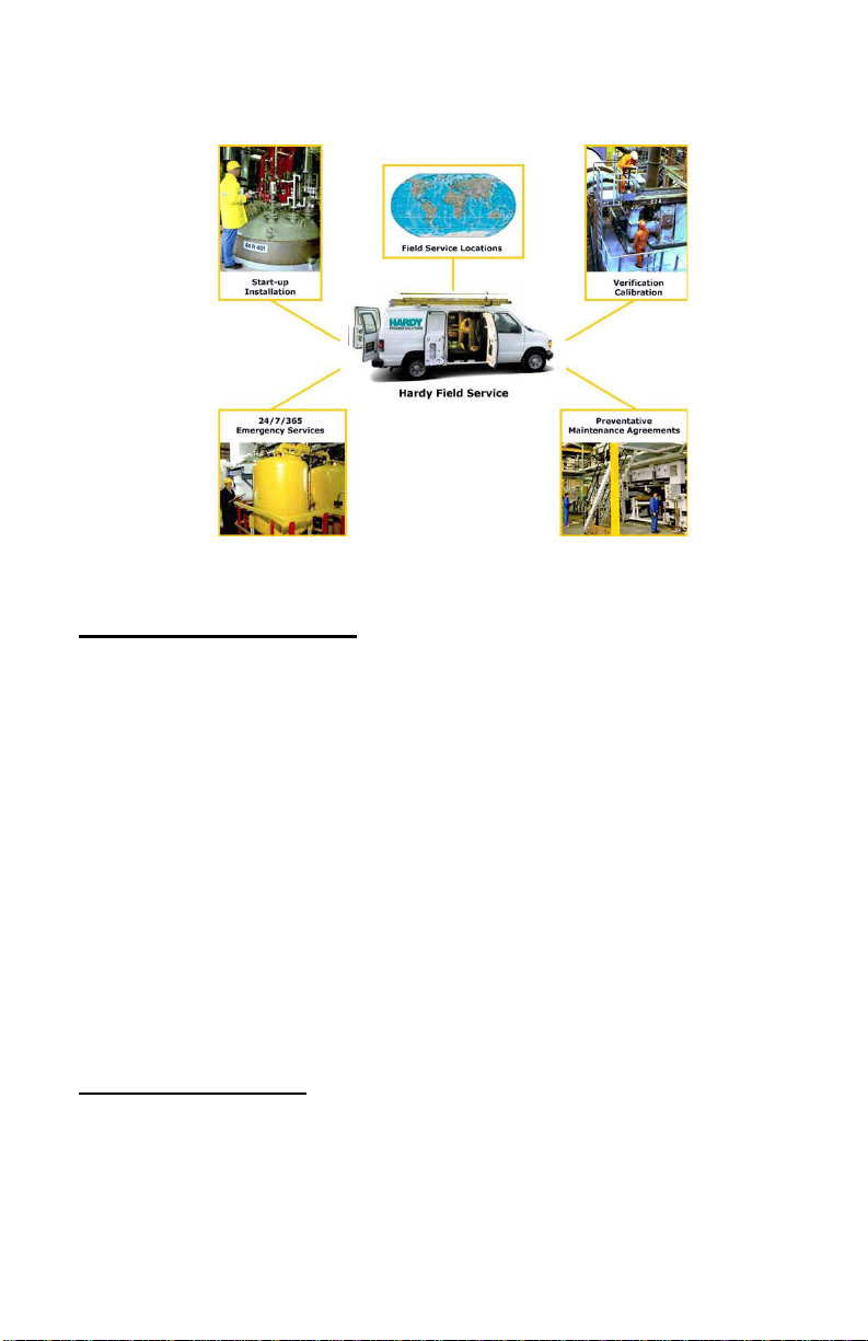
Local Field Service
Hardy has over 200 field technicians in the U.S., and more positioned
throughout the world to assist you in your support needs. We also have fac
tory engineers who will travel to your facility anywhere in the world to help you
solve challenging applications. We're ready to support you with:
• Installation and start-up
• Routine maintenance and certification
• Plant audits and performance measurement
• Emergency troubleshooting and repair
To request Emergency Service and Troubleshooting, Start-up, Installation,
Calibration, Verification or to discuss a Maintenance Agreement please call
800-821-5831 Option 4 or Emergency Service after hours (Standard Hours
6:00 AM to 5:30 PM Pacific Standard Time) and weekends.
-
Outside the U.S
Hardy Process Solutions has built a network of support throughout the globe.
For specific field service options available in your area please contact your
local sales agent or our U.S. factory at +1 858-292-2710, Option 4
Page 3

Table of Contents
Table of Contents
HI 1769-WS & HI 1769-2WS - - - - - - - - - - - - - - - - - - - -1-1
WEIGH SCALE MODULE - - - - - - - - - - - - - - - - - - - - -1-1
Local Field Service - - - - - - - - - - - - - - - - - - - - - - - - -1-2
Outside the U.S- - - - - - - - - - - - - - - - - - - - - - - - - - -1-2
TABLE OF CONTENTS - - - - - - - - - - - - - - - - - - - - - -1-I
TABLE OF ILLUSTRATIONS- - - - - - - - - - - - - - - - - - - -1-I
OVERVIEW - - - - - - - - - - - - - - - - - - - - - - - - - - - -1-1
A Brief Description of Chapter 1 - - - - - - - - - - - - - - - - - -1-1
About Hardy Manuals- - - - - - - - - - - - - - - - - - - - - - - -1-2
Description - - - - - - - - - - - - - - - - - - - - - - - - - - - - -1-2
WAVERSAVER®- - - - - - - - - - - - - - - - - - - - - - - - - -1-3
C2® Calibration - - - - - - - - - - - - - - - - - - - - - - - - - -1-3
IT ® - - - - - - - - - - - - - - - - - - - - - - - - - - - - - - - -1-4
Digital Volt Meter (DVM) - Optional - - - - - - - - - - - - - - -1-4
Rate of Change - - - - - - - - - - - - - - - - - - - - - - - -1-4
Return to Zero Test - Optional - - - - - - - - - - - - - - - - -1-4
Weighing System Tests - Optional - - - - - - - - - - - - - - -1-4
Auto Zero Tracking - - - - - - - - - - - - - - - - - - - - - - - - -1-5
CHAPTER 2 - SPECIFICATIONS- - - - - - - - - - - - - - - - - -2-1
A Brief Description of Chapter 2- - - - - - - - - - - - - - - - - - -2-1
Specifications for a Standard HI 1769-WS Weigh Scale Module - - -2-1
Maximum Installed Modules - - - - - - - - - - - - - - - - - -2-1
Channels- - - - - - - - - - - - - - - - - - - - - - - - - - - -2-1
Conversion Rate - - - - - - - - - - - - - - - - - - - - - - - -2-1
Averages- - - - - - - - - - - - - - - - - - - - - - - - - - - -2-1
Resolution - - - - - - - - - - - - - - - - - - - - - - - - - - -2-1
Input - - - - - - - - - - - - - - - - - - - - - - - - - - - - - -2-1
Non-Linearity- - - - - - - - - - - - - - - - - - - - - - - - - -2-1
WAVERSAVER®- - - - - - - - - - - - - - - - - - - - - - - -2-1
Common-Mode Rejection- - - - - - - - - - - - - - - - - - - -2-1
Common-Mode Voltage Range - - - - - - - - - - - - - - - - -2-2
Bus Input Voltage- - - - - - - - - - - - - - - - - - - - - - - -2-2
Bus Current Load- - - - - - - - - - - - - - - - - - - - - - - -2-2
Bus Power Load - - - - - - - - - - - - - - - - - - - - - - - -2-2
C2 Calibration Input - - - - - - - - - - - - - - - - - - - - - -2-2
Cable lengths- - - - - - - - - - - - - - - - - - - - - - - - - -2-2
i
Page 4

HI 1769-WS/HI 1769-2WS WEIGH SCALE MODULE
Load Cell Excitation- - - - - - - - - - - - - - - - - - - - - - -2-2
C2 Calibration Output- - - - - - - - - - - - - - - - - - - - - -2-2
Environmental Requirements - - - - - - - - - - - - - - - - - - - -2-2
Temperature Coefficient - - - - - - - - - - - - - - - - - - - -2-2
Operating Temperature Range - - - - - - - - - - - - - - - - -2-2
Storage Temperature Range - - - - - - - - - - - - - - - - - -2-2
Humidity Range - - - - - - - - - - - - - - - - - - - - - - - -2-2
Approvals - - - - - - - - - - - - - - - - - - - - - - - - - - -2-2
Digital Voltmeter - - - - - - - - - - - - - - - - - - - - - - - -2-2
Optional Equipment- - - - - - - - - - - - - - - - - - - - - - - - -2-3
1756 RTA (Remote Termination Assembly - - - - - - - - - - -2-3
RTA Cable Assemblies - - - - - - - - - - - - - - - - - - - - -2-3
HI 215IT Series Junction Box - - - - - - - - - - - - - - - - - -2-3
Default Parameters - - - - - - - - - - - - - - - - - - - - - - - - -2-3
EMI Suppression Core - - - - - - - - - - - - - - - - - - - - - - -2-4
Cable Diameter- - - - - - - - - - - - - - - - - - - - - - - - -2-4
Supression Frequencies - - - - - - - - - - - - - - - - - - - -2-4
Cable Types - - - - - - - - - - - - - - - - - - - - - - - - - -2-4
Physical Dimensions - - - - - - - - - - - - - - - - - - - - - -2-4
CHAPTER 3 - INSTALLATION - - - - - - - - - - - - - - - - - - -3-1
A Brief Description of Chapter 3- - - - - - - - - - - - - - - - - - -3-1
Unpacking - - - - - - - - - - - - - - - - - - - - - - - - - - - - -3-1
Installing the HI 1769-WS or HI 1769-2WS to an Allen-Bradley
Compact or Micro Logix 1500 Processor - - - - - - - - - - - - - -3-2
Installing the HI 1769-WS or HI 1769-2WS onto the CompactLogix
and MicroLogix 1500 Bank - - - - - - - - - - - - - - - - - - - - -3-2
Installing the Module I/O Connector - - - - - - - - - - - - - - - - -3-4
About the Module I/O Connector - - - - - - - - - - - - - - - -3-4
Installing the HI 1769-WS on a Din Rail - - - - - - - - - - - - - - -3-7
Load Cell Wiring Diagrams - - - - - - - - - - - - - - - - - - - - -3-10
Industry Standard Load Cells - - - - - - - - - - - - - - - - - -3-10
Hardy Load Sensor with C2 - - - - - - - - - - - - - - - - - - -3-11
HI 1769 Remote Terminal Assembly (HI 1769-XX-RT)- - - - - -3-11
RTA Cable Assembly - - - - - - - - - - - - - - - - - - - -3-12
EMI Suppression Core Installation (Prt. #2547-0013) - - - - - -3-14
Hardy HI 215IT Junction Box - - - - - - - - - - - - - - - - - -3-16
CHAPTER 4 - SETUP - - - - - - - - - - - - - - - - - - - - - - -4-1
A Brief Description of Chapter 4- - - - - - - - - - - - - - - - - - -4-1
Power Check - - - - - - - - - - - - - - - - - - - - - - - - - - - -4-1
LEDS- - - - - - - - - - - - - - - - - - - - - - - - - - - - - -4-2
Scale Data LEDs - - - - - - - - - - - - - - - - - - - - - -4-2
ii
Page 5

Table of Contents
OK Module Status LED - - - - - - - - - - - - - - - - - - -4-2
Setting Up Communications Between the MicroLogix 1500
Processor and the HI 1769-WS & HI 1769-2WS Weigh Scale
Modules - - - - - - - - - - - - - - - - - - - - - - - - - - - - - -4-3
Alternative Setup Procedures - - - - - - - - - - - - - - - - - - - -4-5
Configuring the HI 1769-WS in RSLogix 500 for
MicroLogix 1500 - - - - - - - - - - - - - - - - - - - - - - - -4-5
Configuring the HI 1769-WS in RSLogix 5000 for CompactLogix-4-7
Parameters for the HI 1769-WS Module- - - - - - - - - - - - - - -4-10
About Parameters - - - - - - - - - - - - - - - - - - - - - - -4-10
Configuration Parameters for the HI 1769-WS Module - - - - - - - -4-12
Commands- - - - - - - - - - - - - - - - - - - - - - - - - - - - -4-15
About Commands - - - - - - - - - - - - - - - - - - - - - - -4-15
Command Operation - - - - - - - - - - - - - - - - - - - - - -4-16
Possible COMMAND STATUS Values - - - - - - - - - - - - -4-16
Command Table - - - - - - - - - - - - - - - - - - - - - - - -4-17
Calibration Setup Procedures - - - - - - - - - - - - - - - - - - - -4-24
Setting the Metric Parameter - - - - - - - - - - - - - - - - - -4-24
Setting the Motion Tolerance Value - - - - - - - - - - - - - - -4-24
Setting The Zero Tolerance Value- - - - - - - - - - - - - - - -4-25
Setting the Auto Zero Tolerance Value - - - - - - - - - - - - -4-25
Setting the Number of Readings Averages - - - - - - - - - - -4-25
Setting the Span Weight Value - - - - - - - - - - - - - - - - -4-25
Setting the WAVERSAVER Value- - - - - - - - - - - - - - - -4-25
CHAPTER 5 - CALIBRATION5-1
A Brief Description of Chapter 5- - - - - - - - - - - - - - - - - - -5-1
Pre-Calibration Procedures - - - - - - - - - - - - - - - - - - - - -5-1
Electrical Check Procedures - - - - - - - - - - - - - - - - - - - -5-2
Load Cell/Point Input/Output Measurements- - - - - - - - - - -5-2
Load Check - - - - - - - - - - - - - - - - - - - - - - - - - - - -5-4
C2 Calibration - - - - - - - - - - - - - - - - - - - - - - - - - - -5-5
About C2 Calibration - - - - - - - - - - - - - - - - - - - - - -5-5
C2 Calibration Using Ladder Logic - - - - - - - - - - - - - - -5-5
Hard Calibration - - - - - - - - - - - - - - - - - - - - - - - - - -5-6
Hard Calibration Ladder Logic Example - - - - - - - - - - - - -5-6
CHAPTER 6 - TROUBLESHOOTING- - - - - - - - - - - - - - - -6-1
A Brief Description of Chapter 6- - - - - - - - - - - - - - - - - - -6-1
Scale LED is Flashing Red - - - - - - - - - - - - - - - - - - - - -6-1
Mechanical Inspection - - - - - - - - - - - - - - - - - - - - - - -6-1
Load Sharing and Load Sensor Checkout - - - - - - - - - - - - - -6-3
Guidelines for Instabilities on Formerly Operating Systems - - - - -6-5
iii
Page 6

HI 1769-WS/HI 1769-2WS WEIGH SCALE MODULE
Electrical - - - - - - - - - - - - - - - - - - - - - - - - - - - - - -6-6
Mechanical Stability and Configuration Settings - - - - - - - - - - -6-7
INDEX
iv
Page 7

Table of Illustrations
Table of Illustrations
HI 1769-WS & HI 1769-2WS1-1
WEIGH SCALE MODULE1-1
TABLE OF CONTENTS1-I
TABLE OF ILLUSTRATIONS1-I
OVERVIEW1-1
CHAPTER 2 - SPECIFICATIONS2-1
CHAPTER 3 - INSTALLATION3-1
POSITIONING THE MODULE FOR INSTALLATION3-3
CONNECTOR UNLOCK POSITION3-3
CONNECTOR IN LOCKED POSITION3-4
MODULE CONNECTOR INSTALLED3-6
MODULE CONNECTOR REMOVED FOR EASIER CABLING3-7
RAIL FASTENERS IN RETRACTED POSITION3-8
RAIL FASTENERS IN THE CLOSED POSITION3-9
INDUSTRY STANDARD LOAD CELLS WIRING DIAGRAM3-10
HARDY LOAD SENSOR/C2 WIRING DIAGRAM3-11
REMOTE TERMINAL ASSEMBLY3-12
RTA DIN RAIL MOUNT3-12
RTA CABLE ASSEMBLY - HI 1769-WS3-13
RTA CABLE SCHEMATIC - HI 1769-WS3-13
RTA CABLE - HI 1769-2WS3-13
RTA SCHEMATIC HI 1769-2WS3-14
EMI SUPPRESSION CORE3-15
SUPPRESSION CORE OPEN3-15
SUPPRESSION CORE INSTALLED3-16
HARDY HI 215IT JUNCTION BOX WIRING DIAGRAM3-16
CHAPTER 4 - SETUP4-1
MODULE LEDS HI 1769-WS SINGLE CHANNEL4-1
MODULE LEDS HI 1769-2WS DUAL CHANNEL4-2
I/O CONFIGURATION DIALOG BOX4-3
READ I/O CONFIGURATION FROM ONLINE PROCESSOR DIALOG BOX4-
4
CONNECTION/CONFIGURATION - 484-5
EXPANDING CONTROLLER4-6
I
Page 8

HI 1769-WS/HI 1769-2WS WEIGH SCALE MODULE
I/O CONFIGURATION DIALOG BOX4-6
I/O CONFIGURATION DIALOG BOX4-7
SELECTING COMPACTBUS LOCAL4-8
SELECT MODULE TYPE/SELECTING 1769 MODULE/GENERIC4-8
MODULE PROPERTIES DIALOG BOX/CONFIGURATION/SIZE/0 WORDS4-
9
MODULE PROPERTIES DIALOG BOX/CONFIGURATION/SIZE/48
WORD
S4-9
CONTROLLER TAGS/SLOT 14-15
CHAPTER 5 - CALIBRATION5-1
PROPERLY INSTALLED LOAD CELL W/NO BINDING5-2
MILLIVOLTS/WEIGHT SCALE5-4
CHAPTER 6 - TROUBLESHOOTING6-1
MECHANICAL INSPECTION6-2
LOAD SHARING AND LOAD SENSOR CHECKOUT6-4
GUIDELINES FOR INSTABILITIES ON FORMERLY OPERATING SYS-
TEMS6
-5
GUIDELINES FOR INSTABILITIES ON FORMERLY OPERATING SYSTEMS
- ELECTRICAL6-6
MECHANICAL STABILITY AND CONFIGURATION SETTINGS6-7
INDEX1-1
II
Page 9

CHAPTER 1 - OVERVIEW
Chapter 1 - Overview
A BRIEF DESCRIPTION OF CHAPTER 1
This manual provides the user and service personnel
with a description of the specifications, installation,
setup, configuration, operation, communication,
maintenance, and troubleshooting procedures for the
Hardy HI 1769-WS & HI 1769-2WS Compact and
Micro Logix I/O W eigh Scale Modules that mount on
the Allen-Bradley
MicroLogix™
1769-2WS are equipped with WAVERSAVER
Calibration, and I
®
CompactLogix™ and
1500 platform. The HI 1769-WS & HI
®
, C2®
NTEGRATED TECHNICIAN
®
(IT) diag-
nostics. The module is configurable via ladder logic.
The HI 1769-WS & HI 1769-2WS modules mechani
cally lock together by means of a tongue-and-grove
design and have an integrated communication bus that
is connected from module to module by a moveable
bus connector. To get the maximum service life from
this product, users should operate this module in
accordance with recommended practices either
implied or expressed in this manual. Before using the
Weigh Scale Module, all users and maintenance per
sonnel should read and understand all cautions, warnings, and safety procedures, either referenced or
explicitly stated in this manual, to ensure the safe
operation of the module. Hardy Process Solutions
appreciates your business. Should you not understand
any information in this manual or experience any
problems with the product, please contact our Cus
-
tomer Support Department at:
-
Phone: (858) 278-2900
FAX: (858) 278-6700
e-mail: hardysupport@hardysolutions.com
Web Address: www.hardysolutions.com
NOTE: WAVERSAVER®, C2®, IT® are r egistered trademarks
of Hardy Process Solutions Inc. Integrated T echnician
is a trademark of Hardy Process Solutions Inc.
Allen-Bradley®, CompactLogix ™ and Micr oL ogix ™
1500 are trademarks of the Rockwell Corporation.
1-1
Page 10

HI 1769-WS/HI 1769-2WS WEIGH SCALE MODULE
NOTE: Hardy Pr ocess Solutions bases all procedures with the
assumption that the user has an adequate understand
ing of Allen-Bradley ControlLogix®. In addition the
user should understand process control and be able to
interpret ladder logic instructions necessary to gener
ate the electronic signals that control your application(s).
About Hardy Manuals Every Hardy Installation and Operation manual is
organized into easily referenced chapters, that are
almost always the same:
• Chapter 1 - Provides an introduction to the
instrument and an Overview of the equipment
and its capabilities.
• Chapter 2 - Provides a complete list of Specifi-
cations.
• Chapter 3 - Contains complete instructions
needed to install the HI 1769-WS (both standard
and optional equipment) and the Remote Termi
nation Assembly (-RTA)
• Chapter 4 - Provides complete hardware Con-
figuration instructions for setting dip switches
and jumpers.
• Chapter 5 - Provides all Calibration instructions.
• Chapter 6 - Pertains to the Troubleshooting
procedures for repair of the instrument.
-
-
-
Hardy hopes that this manual meets your needs for
information and operation. All corrections or sugges
tions for improvements of this manual are welcome
and can be sent to the Technical Publications Depart
ment or Customer Support Department at Hardy Process Solutions Inc.
Description The HI 1769-WS & HI 1769-2WS Weigh Scale Mod-
ules are self-contained, microprocessor-based ControlLogix I/O modules with control inputs and
outputs, that is designed to be easily plugged into an
Allen-Bradley CompactLogix or MicroLogix 1500
programmable controller The HI 1769-WS Weigh
Scale Module is a single channel module while the
HI 1769-2WS is configured for dual operation which
1-2
-
-
Page 11

Chapter 1 - Overview
can be used for a wide variety of process weighing
applications such as batching, blending, filling/dis
pensing, check weighing, force measurement, level by
weight and weight rate monitoring. The analog to dig
ital converter in the weigh module controller updates
one hundred (100) times per second and is capable of
8,388,608 counts of display resolution. This gives the
instrument the ability to tolerate large “dead” loads,
over sizing of load cells/sensors and still have suffi
cient resolution to provide accurate weight measurement and control. The module calibration is electronic
via C2 electronic calibration. C2 or Hard (Traditional
calibration with weights) is also available for those
not using Hardy C2 certified load sensors.
-
WAVERSAVER
®
Typically, mechanical noise (from machinery in a
plant environment) is present in forces larger than the
weight forces trying to be detected by the module.
The HI 1769-WS & HI 1769-2WS is fitted with
WAVERSAVER
®
technology which eliminates the
effects of vibratory forces present in all industrial
weight control and measurement applications. By
eliminating the factor of vibratory forces the module
is capable of identifying the actual weight data.
WAVERSAVER
®
can be configured to ignore noise
with frequencies as low as 0.25 Hz. One of five higher
additional cut off frequencies may be selected to pro
vide a faster instrument response time. The default
factory configuration is 1.00 Hz vibration frequency
immunity.
C2® Calibration C2 Second Generation Calibration enables a scale
system to be calibrated electronically without using
certified test weights which equals the systems load
capacity. A C2 weighing system consists of up to
eight (8) C2 load sensors, a junction box, interconnect
cable and an instrument with C2 capabilities as long
as power requirements don’t exceed specification. All
Hardy C2 certified load sensors contain digital infor
mation detailing its unique performance characteristics. The modules read the performance
characteristics of each individual load sensor and
-
-
1-3
Page 12

HI 1769-WS/HI 1769-2WS WEIGH SCALE MODULE
detects the quantity of load sensors in the system. All
calibrations can be performed via ladder logic.
®
IT
INTEGRATED TECHNICIAN™ is a system diagnostics
utility. For full functionality the weigh system should
include an HI 215IT series junction box. Full IT func
tionality allows the operator to rapidly troubleshoot a
weighing system.
-
Digital Volt Meter (DVM) - Optional
Requires the HI 215IT Series Junction Box to monitor
both and mV/V readings for the system and per indi
vidual load sensor. Once a problem is detected by the
operator the DVM readings help the operator to iso
late the faulty component. Further, the DVM readings
can be used to level a system and to make corner
adjustments to platform scales. Accuracy is +/- 2% or
better of full scale.
NOTE: If you do not have the HI 215IT Junction Box con-
nected to the module, the mV/V reading as displayed
is the total for all the load cells on the system.
Rate of Change The ROC option measures and displays the rate at
which a material enters or is dispensed from the scale
over a period of time. ROC data uses a 100-entry reg
ister. New weight values are written to the register at
the rate of 1/100th of the time base. The first register
is subtracted from the 101st Register, which is one
time base older than the first register. The ROC is
reported in units per minute. A time base of discrete
values is selectable from 1 to 1800 sec
Return to Zero Test - Optional
Requires the HI 215IT Series Junction Box to monitor
individual load sensors. This test compares the origi
nal voltage reading (saved at calibration) against the
current voltage reading of an empty vessel. The test
checks for damaged load sensors due to electrical zero
shift or abnormal mechanical forces that cause bind
ing on one or all of the load sensors in the system.
-
-
-
-
-
Weighing System Tests - Optional
1-4
Requires the HI 215IT Series Junction Box for full
utilization. This test is used to diagnose drifting or
unstable weight reading problems. The Weighing Sys
tem Test does the following:
-
Page 13

Chapter 1 - Overview
1. Disconnects the controller and engages an inter-
nal reference signal to see if the problem is within
the instrument.
2. Disconnects the load sensors and engages an
internal (in the junction box) reference signal to
see if the cable between the instrument and the
Junction Box is causing the problem.
3. Reads the weight of each load sensor to see if the
load sensor might be causing the problem.
The ability to read the weight seen by each individual
load sensor allows use of this test to make cornering,
leveling and load sharing adjustments to the weighing
system.
AUTO ZERO TRACKING
Auto Zero Tracking indicates zero weight, as long as
any “live weight” on the scale is below the set Auto
Zero Tolerance, this function is turned on and the
scale is not in motion. This capability allows the mod
ule to ignore material build-up in the weighing system
within a pre-set auto zero tolerance.
-
1-5
Page 14

HI 1769-WS/HI 1769-2WS WEIGH SCALE MODULE
1-6
Page 15

CHAPTER 2 - SPECIFICATIONS
Chapter 2 - Specifications
A Brief Description of Chapter 2
Specifications for a Standard HI 1769-WS Weigh Scale Module
Maximum Installed Modules
Channels 1 Channel HI 1769-WS
Conversion Rate 100 updates per second Averages 1-255 User Selectable in single increments Resolution Internal: 1:8,388,608
Chapter 2 lists the specifications for the HI 1769-WS
& HI 1769-2WS Weigh Scale Modules. Specifica
tions are listed for the standard instrument and for
optional equipment. The specifications listed are
designed to assist in the installation, operation and
troubleshooting of the instrument. All service person
nel should be familiar with this section before
attempting an installation or repair of this instrument.
8 modules - per power supply in a single bank (Module(s) must be installed within 4 slots on either side of
the power supply)
2 Channel HI 1769-2WS
-
-
Input Up to four (4) 350 ohm Full Wheatstone Bridge,
Strain Gauge Load Sensors/Cells (5 volt excitation)
on one vessel.
Non-Linearity 0.0015% of Full Scale
WAVERSAVER
Common-Mode Rejection
®
User Selectable
• 4.00 Hz
• 2.00 Hz
• 1.00 Hz (Default)
• 0.50 Hz
• 0.25 Hz
•OFF
120dB from 59 to 61 Hz
2-1
Page 16

HI 1769-WS/HI 1769-2WS WEIGH SCALE MODULE
Common-Mode Vo ltage Range
Bus Input Voltage 5 VDC Bus Current Load <0.5 Amp at 5 VDC Bus Power Load < 5W at 5 VDC C2 Calibration
Input
Cable lengths 500 feet maximum of C2 authorized cable
Load Cell Excitation
C2 Calibration Output
Environmental Requirements
Temperature Coefficient
2.5VDC maximum (with respect to earth ground)
Isolation from digital section 1000 VDC minimum.
250 feet maximum of C2 authorized cable (Maximum
of 4 load sensors) with IT Junction box.
5 VDC
Isolation from digital section 1000 VDC minimum
Less than 0.005% of full scale per degree C for CalLO and Cal-HI reference points
Operating Temperature Range
Storage Temperature Range
Humidity Range 0-95% (non-condensing) Approvals CE, UL/CUL, Class I, Division 2 Groups A, B, C, D
Digital Voltmeter Accuracy 10% of full scale
2-2
0o C to 60o C (32o F to 140o F)
-40o C to 85o C (-40o F to 185o F)
Temperature Code T5
Resolution
• mV/V 4 digits to the right of the decimal
Page 17

Optional Equipment
Chapter 2 - Specifications
1756 RTA (Remote Termination Assembly
RTA Cable Assemblies
HI 215IT Series Junction Box
Default Parameters
Hardy Part # -RTA (HI-1769-XX-RTA if ordered separately) Remote Termination supports two (2) separate HI 1769-WS or HI 1769-2WS weigh scale
modules. Unit includes DIN rail mounting for 35mm
x 15mm DIN rail.
Hardy Part # -C6 (HI 1769-XX-C6)
• Cable Length: 6 ft. (1.525 meters) from
the single channel module to the RTA.
Hardy Part # - D8 (HI 1769-XX-DC6)
• Cable Length: 6 Ft. (1.525 meters) from
2 single or one dual module to the RTA.
NEMA rated waterproof enclosure which sums from
one to four load sensors load sensors.
• -PS1 NEMA 4 Painted Steel
• -SS1 NEMA 4X Stainless Steel
• -FG1 NEMA 4X Fiberglass
Parameter Default Setting
ChanActive On 1
Calib Type none OXFFFF
Tareweight 0.0 lbs 0
Metric lbs 0
WAVERSAVER
SpanWeight 10,000.00 10,000.00
CalLowWeight 0 lbs 0
Num Averages 10 10
ROC Timebase 10 sec 10
®
1 Hz 3
Table 2-1: Default Parameters
2-3
Page 18

HI 1769-WS/HI 1769-2WS WEIGH SCALE MODULE
Parameter Default Setting
ZeroTrackEnable False 0
ZeroTolerance 10.0 lbs 10.0
AutoZeroTolerance 10.0 lbs 10.0
MotionTolerance 5.0 lbs 5.0
Table 2-1: Default Parameters
EMI Suppression Core
Cable Diameter .250 inches Max. (6.4 mm Max) Supression
Up to 500 MHz
Frequencies
Cable Types • Multi-strand
• Single Conductor
Physical Dimensions
Width - .705 inches (17.9 mm)
Height - .724 inches (18.39 mm)
Length - 1.272 inches (32.3 mm)
2-4
Page 19

CHAPTER 3 - INSTALLATION
Chapter 3 - Installation
A Brief Description of Chapter 3
Unpacking Step 1. Before signing the packing slip, inspect
All information contained in Chapter 3 pertains to
unpacking, cabling, interconnecting, configuration
and installing the Weigh Scale Module. Alternatives
to any procedures contained or implied in this chapter
are not recommended. It is very important that the
user and service personnel be familiar with the proce
dures contained in this chapter, before installing or
operating the Weigh Scale module. Hardy Process
Solutions appreciates your business. Should you
experience any problems installing this equipment,
contact Hardy Customer Support for assistance.
the packing for damage of any kind.
Step 2. Report any damage to the carrier company
immediately.
Step 3. Check to see that everything in the pack-
age matches the bill of lading. You should
normally have:
• HI 1769-WS or HI 1769-2WS
Weigh Scale Module
• Operation & Installation Manual
Step 4. Write down the Model and Serial number
of the module. Store this information in a
convenient location for reference when
contacting The Customer Support Depart
ment for parts or service.
-
-
WARNING EXPLOSION HAZARD - DO NOT DISCON-
NECT WHILE CIRCUIT IS ALIVE UNLESS
AREA IS KNOWN TO BE NON-HAZARDOUS.
WARNING EXPLOSION HAZARD - SUBSTITUTION OF
COMPONENTS MAY IMPAIR SUITABILITY
FOR CLASS I, DIVISION 2.
WARNING RISK OF FIRE OR EXPLOSION. DO NOT
OPERATE SWITCH WHILE CIRCUIT IS LIVE.
3-1
Page 20

HI 1769-WS/HI 1769-2WS WEIGH SCALE MODULE
Installing the HI 1769-WS or HI 1769-2WS to an Allen-Bradley CompactLogix or MicroLogix 1500 Processor
WARNING ELECTROSTATIC DISCHARGE MAY DAM-
AGE SEMICONDUCTOR COMPONENTS. DO
NOT TOUCH THE CONNECTOR PINS AND
OBSERVE THE FOLLOWING HANDLING
PRECAUTIONS:
• Wear an approved wrist-strap grounding
device when handling the module.
• Touch a grounded object or surface to rid
yourself of any electrostatic discharged prior
to handling the module.
• Handle the module from the bezel in front
away from the connector. Never, NEVER
touch the connector pins.
• Wiring mus t be in accordance with Class I,
Division 2 wiring methods of the National
Electrical Code, NFPA 70 and acceptable to
the authority having jurisdiction.
• Do not install the module right next to an AC
or high voltage DC module.
• Route all the load voltage cables away from
high voltage cables.
Installing the
HI 1769-WS or
HI 1769-2WS onto
the CompactLogix
and MicroLogix
1500 Bank
3-2
Step 1. Make sure that the module is oriented cor-
rectly for installation. (See Fig. 3-1)
Page 21
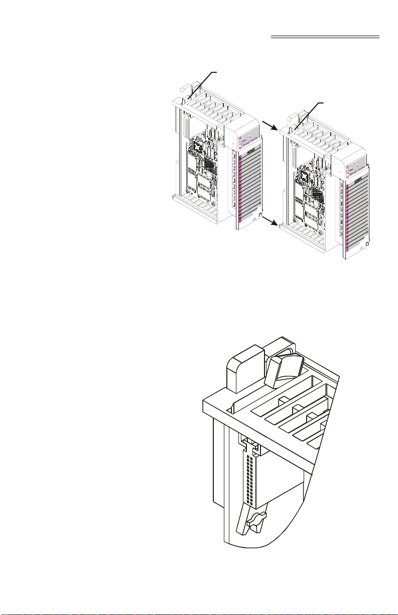
Chapter 3 - Installation
Module A
Module B
Lever A
Lever B
FIG. 3-1 POSITIONING THE MODULE FOR
INSTALLATION
Step 2. Pull Lever B back to the unlock position.
FIG. 3-2 CONNECTOR UNLOCK POSITION
3-3
Page 22
HI 1769-WS/HI 1769-2WS WEIGH SCALE MODULE
Step 3. Gently slide the HI 1769-WS or HI 1769-
2WS module onto the other module. In our
example we connected two Hardy HI
1769-WS Weigh Modules.
Step 4. When you have the modules aligned, press
Lever B towards Module A to fasten the
connector to Module A. (See Fig. 3-3)
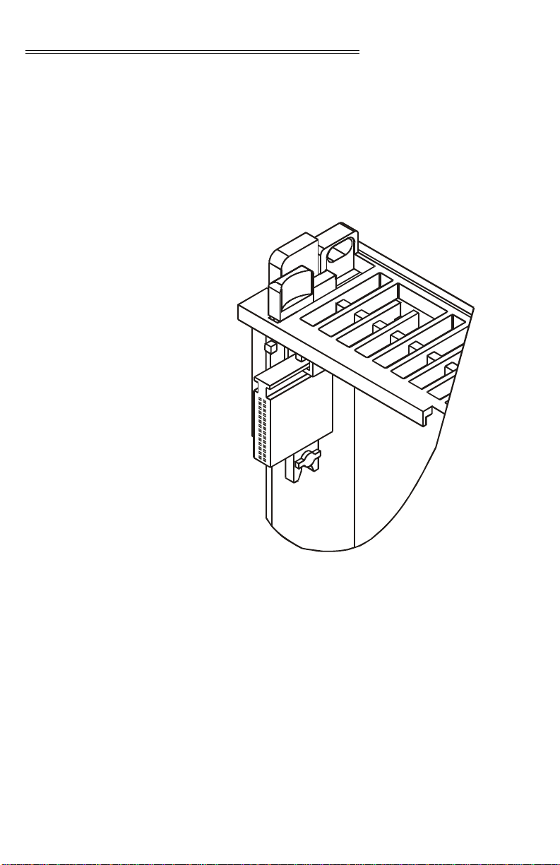
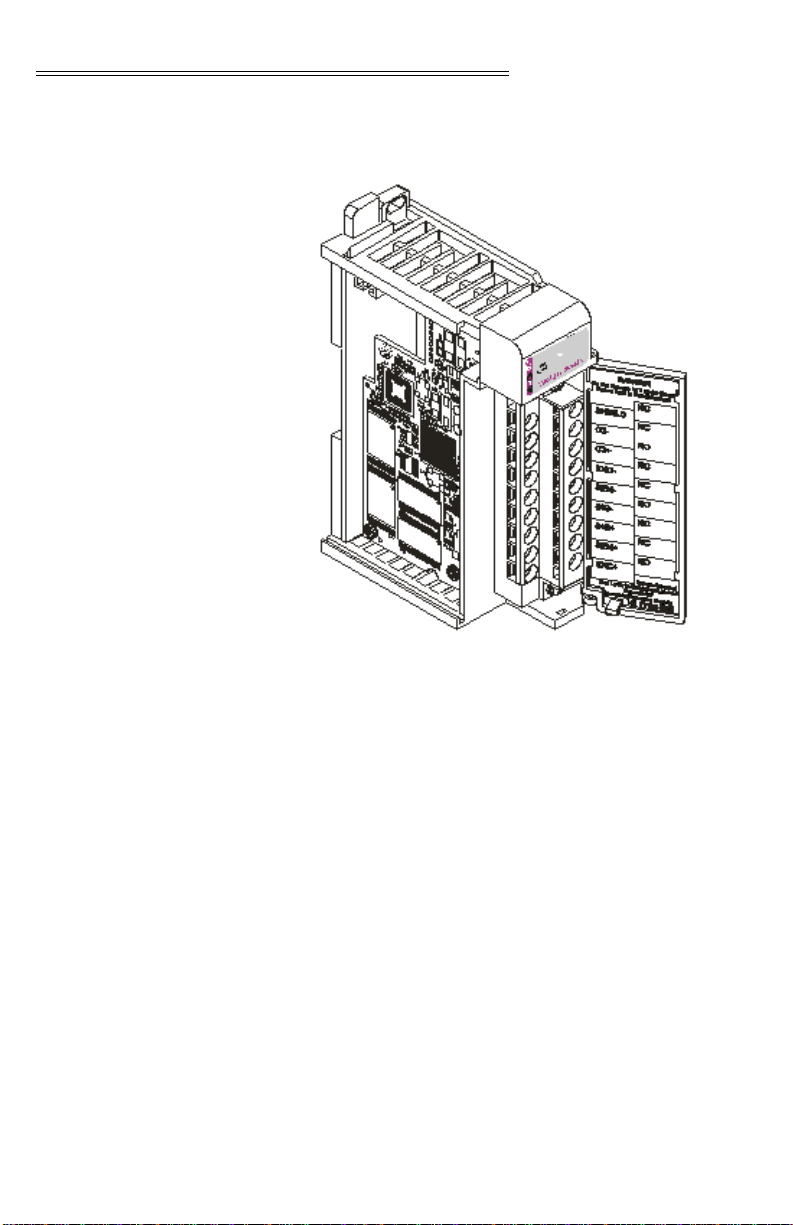
Installing the Module
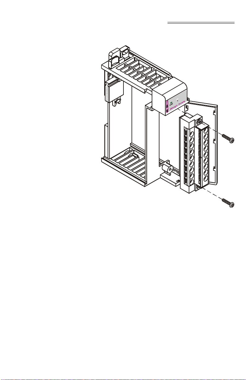
I/O Connector
About the Module I/O Connector
3-4
FIG. 3-3 CONNECTOR IN LOCKED POSITION
Step 5. The installation is comple.
The I/O Connector at the front of the module connects
the module to the Remote Terminal Assembly (RTA), a load sensor, or the HI 215IT Series Junction
Box depending on how many load sensors are
installed in the weighing system. See below for the
pin-out diagram. The pin-out diagram is located on
the inside of the module door. (See Fig. 3-4)
Page 23

Chapter 3 - Installation
Single Channel
Pin 1 Shield1
Pin 3 C2-1
Pin 5 C2+1
Pin 7 Exc-1
Pin 9 Sen-1
Pin 11 Sig-1
Pin 13 Sig+1
Pin 15 Sen+1
Pin 17 Exc+1
Dual Channel
Pin 1 Shield1
Pin 3 C2-1
Pin 5 C2+1
Pin 7 Exc-1
Pin 9 Sen-1
Pin 11 Sig-1
Pin 13 Sig+1
Pin 15 Sen+1
Pin 17 Exc+1
Pin 2 Shield2
Pin 4 C2-2
Pin 6 C2+2
Pin 8 Exc-2
Pin 10 Sen-2
Pin 12 Sig-2
Pin 14 Sig+2
Pin 16 Sen+2
Pin 18 Exc+2
Step 1. Open the Module door to gain access to
the I/O connector. (See Fig. 3-4)
Step 2. To make the cable connections easier you
can remove the connector from the mod
ule. To remove the connector, use a phillips screw driver and remove the two (2)
phillips pan head screws that fasten the
connector to the module. (See Fig. 3-5)
Step 3. Gently pull the connector off of the board
in the module.
3-5
Page 24
HI 1769-WS/HI 1769-2WS WEIGH SCALE MODULE
Step 4. To install the connector reverse steps 2 &
3.
3-6
FIG. 3-4 MODULE CONNECTOR INSTALLED
Page 25
Chapter 3 - Installation
FIG. 3-5 MODULE CONNECTOR REMOVED
FOR EASIER CABLING
Step 5. Install the cable so it allows the module
door to close.
Step 6. Check to be sure that the wires are
securely connected before operating the
module.
NOTE: Most of the problems with modules are due to loose
connections. Be sure to check the I/O connection first
in the event you have a problem r eceiving information
from the load cells.
Installing the HI 1769WS on a Din Rail
Step 1. Pull the two DIN rail fasteners out until
they snap into the open position. (See Fig.
3-6)
3-7
Page 26

HI 1769-WS/HI 1769-2WS WEIGH SCALE MODULE
FIG. 3-6 RAIL FASTENERS IN RETRACTED
POSITION
Step 2. Place the module on the DIN rail.
Step 3. While holding the module in place, press
the two rail fasteners towards the center of
the module until they both snap into place.
(See Fig. 3-7)
Step 4. The module is now securely fastened to
the DIN Rail.
Step 5. To remove the module from the DIN rail
reverse steps 2 & 3 above.
Rail
Fasteners
3-8
Page 27

Chapter 3 - Installation
FIG. 3-7 RAIL FASTENERS IN THE CLOSED
POSITION
3-9
Page 28

HI 1769-WS/HI 1769-2WS WEIGH SCALE MODULE
Load Cell Wiring Diagrams
Industry Standard Load Cells
FIG. 3-8 INDUSTRY STANDARD LOAD CELLS
WIRING DIAGRAM
3-10
Page 29

Hardy Load Sensor with C2
Chapter 3 - Installation
FIG. 3-9 HARDY LOAD SENSOR/C2 WIRING
DIAGRAM
WARNING: HARDY PROCESS SOLUTIONS RECOM-
MENDS THAT YOU DO NOT CUT YOUR
ADVANTAGE
® OR ADVANTA GE LITE® LOAD
SENSOR CABLE, BECAUSE YOUR C2®
ACCURACY WILL BE AFFECTED AND
THE WARRANTY VOIDED.
HI 1769 Remote Terminal Assembly (HI 1769-XX-RT)
Provides connection points between the cable assembly from the HI 1769-WS module and the individual
wires from the junction box(es) or load sensor(s). (See
Fig. 3-10) The RTA can be mounted on a DIN Rail.
(See Fig. 3-11)
3-11
Page 30

HI 1769-WS/HI 1769-2WS WEIGH SCALE MODULE
59mm
(2.3")
FIG. 3-10 REMOTE TERMINAL ASSEMBLY
3-12
RTA Cable Assembly
FIG. 3-11 RTA DIN RAIL MOUNT
• Six (6) foot cable and schematic that connects to
the HI 1769-WS module. (See Figs. 3-12& 3-13)
Page 31

Chapter 3 - Installation
FIG. 3-12 RTA CABLE ASSEMBLY - HI 1769-
WS
FIG. 3-13 RTA CABLE SCHEMATIC - HI 1769-
WS
• Six (6) foot cable that connects to the HI 1769-
2WS. (See Figs. 3-14 & 3-15)
FIG. 3-14 RTA CABLE - HI 1769-2WS
3-13
Page 32

HI 1769-WS/HI 1769-2WS WEIGH SCALE MODULE
FIG. 3-15 RTA SCHEMATIC HI 1769-2WS
EMI Suppression Core Installation (Prt. #2547-0013)
NOTE: Install one suppression core for the single channel
For CE requirements you will need to install an EMI
suppression core around the multi-strand portion of
the RTA cable. (See Fig. 3-12 & 3-14)
model and two (2) suppression cores for the dual
channel model.
Step 1. There should be enough of the individual
strands of wire exposed to install the sup
pression core. If there is not enough room,
remove enough of the cable cover until
you can place the suppression core around
all the wire strands.
Step 2. Place the suppression core as close to the
module door as possible and still be able to
close the door.
Step 3. To open the suppression core place a small
slotted screwdriver behind the latch and
pry the latch away from the body of the
core until it clears both catches. (See Fig.
3-16)
-
3-14
Page 33

Chapter 3 - Installation
Latch
FIG. 3-16 EMI SUPPRESSION CORE
Step 4. Open the core until it is wide enough to
enclose all the strands of wire. (See Fig. 3-
17)
FIG. 3-17 SUPPRESSION CORE OPEN
Step 5. Place all the wire strands in the core and
gently close the core until it snaps shut.
(See Fig. 3-18)
3-15
Page 34

HI 1769-WS/HI 1769-2WS WEIGH SCALE MODULE
FIG. 3-18 SUPPRESSION CORE INSTALLED
Hardy HI 215IT Junction Box
FIG. 3-19 HARDY HI 215IT JUNCTION BOX
WIRING DIAGRAM
NOTE: When connecting the Hardy HI 215IT Junction Box
you must remove the two factory installed jumpers
17&15 and 7&9 on the module install sense lines
except when installing four (4) wire non C2 load cells.
3-16
Page 35

CHAPTER 4 - SETUP
Chapter 4 - Setup
A Brief Description of Chapter 4
Power Check Step 1. Check to see that there is power to the
All information contained in Chapter 4 pertains to
firmware and software settings to prepare the module
controller for calibration and operation. Alternatives
to these procedures either explicit or implied, con
tained in this section are not recommended. It is very
important that the user and service personnel be
familiar with the procedures contained in this chapter,
before going through the setup procedures. The Setup
procedures require Allen-Bradley’s RS Logix 5000
(CompactLogix) or RS Logix 500 (MicroLogix 1500)
Allen-Bradley RSLinx™ or RSLinx™ Lite.
PLC and the module.
Step 2. If there is power to the module, the LEDS
should be lit. (See Fig. 4-1 and 4-2)
Step 3. To make any settings the LED’s should be
lit for normal operation:
-
FIG. 4-1 MODULE LEDS HI 1769-WS SINGLE
CHANNEL
4-1
Page 36

HI 1769-WS/HI 1769-2WS WEIGH SCALE MODULE
FIG. 4-2 MODULE LEDS HI 1769-2WS DUAL
CHANNEL
LEDS The module has a Scale LED and an OK LED associ-
ated with it. The LEDs may be green, red or off. They
may be steady, Fast Flashing (5 Hertz) of Slow Flash
ing (1 Hertz)
-
Scale Data LEDs
OK Module Status LED
NOTE: Slow Flashing Red appears briefly when powering up.
NOTE: *Contact Hardy Customer Support for assistance.
4-2
Steady Green Running (Normal)
Slow Flashing Green Error No Calibration
Steady Red Error ERRORADFAILURE -
(hardware induced) status bit is
set.
Flashing Red Read AD Convert Error.
LED is Off Channel is not Enabled
Fast Flashing Green Module communicating with
PLC. (Normal)
Slow Flashing Red Module is not Communicating
with the PLC (Not Normal)
Error, configuration/error in
PLC addressing
Page 37

Chapter 4 - Setup
Setting Up
Communications
Between the
MicroLogix 1500
Processor and the
HI 1769-WS & HI 17692WS Weigh Scale
Modules
NOTE: On the side of the module you will see a label that
reads either Firmware REV A or Firmware REV
B,C,D etc. Both setup procedures are the same except
for the Connection Parameters/Extra Data Length.
For REV A the setting is 0. For all other REVs the set
ting is 48.
To set up communication between the MicroLogix
1500 Processor and the W eigh Scale Module you will
need to do the following in RSLogix 500:
Step 1. We assume you have a project open or
have created a new project. For instruc
tions please see your RS LOGIX 500 manual. The setup instructions begin from this
point.
Step 2. From the I/O Configuration dialog box,
under “#” column heading click on #1 or
the next open slot number available. (See
Fig. 4-3)
-
-
FIG. 4-3 I/O CONFIGURATION DIALOG BOX
4-3
Page 38

HI 1769-WS/HI 1769-2WS WEIGH SCALE MODULE
Step 3. Click on the “Read IO Config” button.
(See Fig. 4-4) The “Read IO Configuration
from Online Processor” dialog box
appears. (See Fig. 4-5)
Step 4. RSLogix 500 automatically reads the I/O
information and enters them into the con
figuration text fields. (See Fig. 4-4)
-
4-4
FIG. 4-4 READ I/O CONFIGURATION FROM
ONLINE PROCESSOR DIALOG BOX
Step 5. The HI 1769-WS I/O is configured and
ready to communicate with the
MicroLogix 1500 Processor.
Step 6. For Firmware REV B you need to double
click on the module which opens the Con
nection Parameters dialog box. Change the
Extra Data Length from a 0 to 48. (See
Fig. 4-5)
-
Page 39

Alternative Setup Procedures
Configuring the
HI 1769-WS in
RSLogix 500 for
MicroLogix 1500
Chapter 4 - Setup
FIG. 4-5 CONNECTION/CONFIGURATION - 48
To set up communication between the MicroLogix
1500 Processor and the W eigh Scale Module you will
need to do the following in RSLogix 500:
Step 1. Under Project, click on the + next to con-
troller. (See Fig. 4-6)
Step 2. Click on I/O Configuration. The I/O Con-
figuration dialog box appears. (See Fig. 4-
7)
4-5
Page 40

HI 1769-WS/HI 1769-2WS WEIGH SCALE MODULE
FIG. 4-6 EXPANDING CONTROLLER
4-6
FIG. 4-7 I/O CONFIGURATION DIALOG BOX
Step 3. From the I/O Configuration dialog box,
under the “#” column heading, click on #1
or the next open slot number available.
(See Fig. 4-8)
Step 4. In the Current Cards Available, double
click on “Other - Requires I/O Type Card
ID” under the Description column head
ing.
Step 5. Enter the following in the appropriate text
fields:
-
Page 41

Chapter 4 - Setup
On some PLC platforms it may be necessary to enter
the Vendor ID, the Product Type, the Product Code,
Input/Output Words and Extra Data Length. See
below:
• HARDY_VENDOR_ID 0x102 (258 decimal)
• HARDY_PRODUCT_TYPE 0x54 (100 decimal)
• HARDY_PRODUCT -CODE 5
• Input Words - 32
• Output Words - 32
• Extra Data Length - 0 for Firmware REV A or 48
for later Firmware REVs.
Step 6. Click on the “Apply.” button.
Step 7. “OTHER” appears under the Part # col-
umn heading. (See Fig. 4-8)
Configuring the
HI 1769-WS in
RSLogix 5000 for
CompactLogix
FIG. 4-8 I/O CONFIGURATION DIALOG BOX
Step 8. The HI 1769-WS I/O is configured and
ready to communicate with the
MicroLogix 1500 Processor.
T o set up communication between the CompactLogix
Processor and the We igh Scale Module you will need
to do the following in RSLogix 5000:
Step 1. Click on the + next to I/O Configuration.
(See Fig. 4-9).
4-7
Page 42

HI 1769-WS/HI 1769-2WS WEIGH SCALE MODULE
FIG. 4-9 SELECTING COMPACTBUS LOCAL
Step 2. Right click on
“CompactBus
Local”. A dia
log box appears.
Step 3. Click on “New
Module”. The
“Select Module
Type” dialog
box appears. (See Fig. 4-10)
-
4-8
FIG. 4-10 SELECT MODULE TYPE/
SELECTING 1769 MODULE/GENERIC
Page 43

Chapter 4 - Setup
Step 4. From the Select Module Type dialog box,
scroll down the list until you find the 1769
Module - Generic Module.
Step 5. Double click on the 1769 Generic Module.
Step 6. Click on the OK button. The Module Prop-
erties dialog box appears. (See Figs. 4-11
& 12)
FIG. 4-11 MODULE PROPERTIES DIALOG
BOX/CONFIGURATION/SIZE/0 WORDS
FIG. 4-12 MODULE PROPERTIES DIALOG
BOX/CONFIGURATION/SIZE/48 WORDS
Step 7. Click in the Name Text box. Enter a
descriptive name for the module. We used
“Hardy_1769WS” for example.
4-9
Page 44

HI 1769-WS/HI 1769-2WS WEIGH SCALE MODULE
Step 8. Click in the Description Text Box. Type in
a description of the module.
Step 9. Click on the down arrow to the right of
Comm Format to open the pull down list.
Step 10. Click on Data-INT to select the Comm
Format.
Step 11. Use the up or down arrows to the right of
Slot, to select the slot number for the
installed HI 1769-WS or HI 1769-2WS.
Step 12. Under Connection Parameters/Input use
the up or down arrows to select 32 words.
Step 13. Under Connection Parameters/Output use
the up or down arrows to select 32 words.
Step 14. Under Connection Parameters/Configura-
tion use the up or down arrows to select:
• For Firmware REV A - 0 words.
• For other Firmware REVs - 48 words.
Step 15. Click on the “Finish” button.
Parameters for the
HI 1769-WS Module
About Parameters The data types that can appear in the I/O files are:
• 16 bit integer
• 32 bit integer
• 32 bit IEEE float.
NOTE: In the 32 bit types, the least significant word comes
first, followed by the most significant word.
Weight values are displayed as either 32 bit integers,
or as 32 bit float depending on the value of the “Met
ric” parameter. (See Parameter Table 4-1 below)
Each channel has a CHANNEL STATUS WORD,
with bits set to indicate the state of that channel. The
bit values are:
4-10
-
Page 45

Chapter 4 - Setup
• #define ERRORADCONVERT 0x0001
• #define ERRORADFAILURE 0x0002
• #define STATUSINMOTION 0x0040
• #define ERRORNOCAL 0x0080
• #define ERROREEPROMWRITE 0x0100
// an error occurred when writing to nonvolatile memory
• #define NVRDEFAULTED 0x0200 // set
if SETDEF AULTPA RAMS command was
given
• #define STATUSCHANENABLED
0x8000 // set if channel is enabled
Name Description Default
ChanActive 16 bit integer, set to 1 if the
channel is active, 0 if not
active
Metric 16 bit integer which
determines the format of
weight values. Metric is the
sum of 3 fields:
1 If bit 7 is set (0x80),
weight is displayed in
Kilograms
2 If bit 6 is set (0x40),
weight is displayed as a
floating point
3. If bit 6 is not set, Weight
is displayed as an
integer, with the 3 least
significant bits giving the
number of decimal
places
WAVERSAVER 16 bit integer
0 No WAVERSAVER
14 Hertz
22 Hertz
31 Hertz
4 0.5 Hertz
5 0.25 Hertz
TABLE 4-1: PARAMETERS
1
0 (weight in pounds, integer
format, 0 decimal places)
3 (1 Hertz)
4-11
Page 46

HI 1769-WS/HI 1769-2WS WEIGH SCALE MODULE
Name Description Default
NumAverages 16 bit integer, 1-255 20
ZeroTrackEnable 16 bit integer
0 turns auto-zero tracking off
1 turns auto-zero tracking on
AutoZeroTolerance 32 bit weight value, format
determined by value of
Metric Parameter
ZeroTolerance 32 bit weight value, format
determined by value of
Metric Parameter
Motion Tolera nce 32 bit weight value, format
determined by value of
Metric Parameter
tareweight 32 bit weight value, format
determined by value of
Metric Parameter.
SpanWeight 32 bit weight value, format
determined by value of
Metric Parameter.
Span Weight is the test weight
used at the high step of a hard
calibration
ROCtimebase 16 bit integer, 1-1800 seconds 10 secs
CalLowWeight 32 bit weight value, format
determined by value of
Metric Parameter
CalLowWeight is the test
weight used at the low step of
a hard calibration and as Ref
Point for C2 Calibration
0
10.0 lbs.
10.0 lbs.
5 lbs
0 lbs.
10,000.0 lbs
0 lbs
Configuration Parameters for the HI 1769-WS Module
4-12
TABLE 4-1: PARAMETERS
The HI 1769-WS & HI 1769-2WS are equipped with
Firmware REV B have 48 words of configuration
data. The HI 1769-WS Firmware REV B has 48
words of configuration data for CompactLogix and
Extended Data on MicroLogix, 24 w ords per channe l.
Page 47

Chapter 4 - Setup
The configuration data is sent from the PLC to the HI
1769-WS module at power-up. The module uses these
parameters provided that:
1. The parameters are in the correct range. Illegal values will be rejected.
2. The “CopyConfig” word (0 for channel 0, 24
for channel 1) is set to 1.
• INT parameters are 2 byte integers
• DINT parameters are 4 byte integers
• REAL parameters are 4 byte IEEE
floating point numbers
NOTE: Parameters labeled “REAL or DINT” will be inter-
preted as floating point or integer according to the
value of the “METRIC” parameter of the channel. If
bit 6 (0x40) of METRIC is set the parameter is float
ing point. If bit 6 is not set, it is a fixed point integer,
with 0-7 decimal places as determined the first 3 bits
of the METRIC parameter.
-
Parameter
Ch0CopyConfig 0 INT
Ch0ChanActive 1 INT
Ch0Metric 2 INT
Ch0Waversaver 3 INT
Ch0NumAverages 4 INT
Ch0ZeroTrackEnable 5 INT
Ch0AutoZeroTolerance 6 REAL or INT
Ch0MotionTolerance 8 REAL or INT
Ch0ZeroTolerance 10 REAL or INT
Ch0SpanWeight 12 REAL or INT
Offset (In
Words)
Data Type
4-13
Page 48

HI 1769-WS/HI 1769-2WS WEIGH SCALE MODULE
Parameter
Ch0CalLowWeight 14 REAL or INT
Ch0ROCtimebase 16 INT
Ch0CopyCal 17 INT
Ch0calzerocount 18 DINT
Ch0CalHighCount 20 DINT
Ch0Spare2 22 INT
Ch0Spare3 23 INT
Ch1CopyConfig 24 INT
Ch1ChanActive 25 INT
Ch1Metric 26 INT
Ch1Waversaver 27 INT
Ch1NumAverages 28 INT
Ch1ZeroTrackEnable 29 INT
Ch1AutoZeroTolerance 30 REAL or INT
Ch1MotionTolerance 32 REAL or INT
Offset (In
Words)
Data Type
4-14
Ch1ZeroTolerance 34 REAL or INT
Ch1SpanWeight 36 REAL or INT
Ch1CalLowWeight 38 REAL or INT
Ch1ROCtimebase 40 INT
Ch1CopyCal 41 INT
Ch1calzerocount 42 DINT
Ch1CalHighCount 44 DINT
Ch1Spare2 46 INT
Ch1Spare3 47 INT
It is important to note in CompactLogix that when
you click on Controller Tags you will not get the
Page 49

Chapter 4 - Setup
parameters in the form above. When you expand the
slot you selected for the these parameters they will
look like the following:
Local:1:C.Data[0]
Local:1:C.Data[1]
Local:1:C.Data[2]
Local:1:C.Data[3]
...and so on
These correspond directly to the parameters in the
table above. (See Fig. 4-13)
FIG. 4-13 CONTROLLER TAGS/SLOT 1
Commands
About Commands The first 16 words are reserved for Channel 0. The
second 16 words are reserved for Channel 1. The first
word in the 16 words of a channel’s output table is
called the COMMAND word.
See the COMMAND table for a list of commands.
The other words in the output data table may need to
be set according to which command is being given.
The commands are executed only once, when the
COMMAND word changes. The first word in the
channel’s input table is an echo of the COMMAND
word. All commands take some time to process; when
you see the echoed value in the input table, the com
mand is complete. The second word in the channel’s
-
4-15
Page 50

HI 1769-WS/HI 1769-2WS WEIGH SCALE MODULE
input table is called the command STATUS. Normally , a 0 value of STATUS means that the command
completed OK and a non-zero status indicates some
kind of error.
Command Operation
Possible COMMAND STATUS Values
Step 1. To start a command, place the command
number into the first word of the output
table.
Step 2. The Input Table contains the response for
that command.
Step 3. If a selected command needs other data
with it, the other words in the output table
should be filled in first, then the command
number. Example:
• WRITEPARAM0, should have
PARAMETER0 Data placed into the
output table before the command
number is written, otherwise the com
mand will fail.
• #define SUCCESS 0
• #define ERRORADCONVERT 0x0001
• #define ERRORADFAILURE 0x0002
• #define STATUSINMOTION 0x0040
• #define OUTOFTOLERANCE -3
• #define INDEXOUTOFRANGE -4
• #define NOSUCHCMD -5
• #define C2FAILNODEVS -6
• #define C2FAILCAPEQ -7 // failure, capacities
not equal
• #define HARDCALFAILCOUNST -8 // failure,
not enough ADC counts between high, low
-
4-16
Page 51

Command Table
Chapter 4 - Setup
Command
NOCMD (no command)
0
Give this command to read
weight from the module.
Weight values will then be
continuously updated
ZEROCMD
1
Zeroes the scale:
May fail if the weight is in
motion, or if there is an A/
D error, or if the weight to
be zeroed out is outside the
Zero Tolerance range.
Required Output Table Values
Written by User (PLC)
O:0 = 0
O:1-0:15 (unused)
O:0 = 1
O:1-O:15 (unused)
Input Table Response
From Weigh Scale
I:0 = 0
I:1 = COMMAND STATUS =
0
I:2 = CHANNEL
ST ATUSWORD
I:3 = Firmware Revision
I:4 = Gross Weight, LSW
I:5 = Gross Weight, MSW
I:6 = Net Weight, LSW
I:7 = Net Weight, MSW
I:8 = Metric Parameter
I:9 = Calibration Type
• Hard Calibration = 0
• C2 Calibration = 1
• No Calibration =
0xFFFF
I:10 = ADC Counts, LSW
I:11 = ADC Counts, MSW
I:12 = ROC (units/min)
I:13 = ROC (units/min)
I:14 = Serial Number
I:15 = ADC Conversion
Counter
I:0 = 1
I:1 = COMMAND STATUS
I:2-I:15 See NOCMD
continuously updating
TARECMD
2
Tares the Scale:
May fail if the weight is in
motion, or if there is an A/
D error.
O:0 = 2
O:1-O:15 (unused)
I:0 = 2
I:1 = COMMAND STATUS
I:2-I:15 See NOCMD
continuously updating
4-17
Page 52

HI 1769-WS/HI 1769-2WS WEIGH SCALE MODULE
Command
WRITEMETRIC
3
Writes the Metric
Parameter. Does NOT save
the value of the metric
parameter to non-volatile
memory.
WRITENONVOLATILE
4
This command is normally
not needed, since the
commands that write
parameters automatically
save values to non-volatile
memory. Exceptions are the
ZEROCMD, TARECMD,
and WRITEMETRIC,
which do not automatically
save.
RELOADNONVOLATILE
0X10
Reread the non-volatile
memory
CALLOWCMD
0x64
Do the low step of a Hard
Calibration.
Results saved to nonvolatile memory.
Required Output Table Values
Written by User (PLC)
O:0 = 3
O:1 - unused
O:2 - unused
O:3 - New METRIC value
O:0 = 4
O:1-O:15 (unused)
O:0 = 0x10
O:1-O:15 (unused)
O:0 = 0x64
O:1-O:15 (unused)
Input Table Response
From Weigh Scale
I:0 = 3
I:1 = COMMAND STATUS
I:2-I:15 See NOCMD,
continuously updating
I:0 = 4
I:1 = 0
I:2-I:15 See NOCMD,
continuously updating
I:0 = 0x10
I:1 = 0
I:2-I:15 See NOCMD
continuously updating
I:0 = 0x64
I:1 = COMMAND STATUS
I:2-I:15 See NOCMD,
continuously updating
CALHIGHCMD
0x65
Do the high setpoint of a
Hard Calibration.
Results saved to nonvolatile memory.
C2CALCMD
0x66
Do a C2 Calibration.
Results saved to nonvolatile memory
4-18
O:0 = 0x65
O:1-O:15 (unused)
O:0 = 0x66
O:1-O:15 (unused)
I:0 = 0x65
I:1 = COMMAND STATUS
I:2-I:15 See NOCMD,
continuously updating
I:0 = 0x66
I:1 = COMMAND STATUS
I:2-I:15 See NOCMD,
continuously updating
Page 53

Chapter 4 - Setup
Command
WRITEPARAM0
0x67
Write a block of
parameters:
To write a single parameter:
Step 1. Do a READPAR-
AM0 command.
Step 2. Copy the parame-
ters read to the
output.
Step 3. Change the param-
eter value
Step 4. Set the command
word.
The Metric Parameter is
processed last, which
means that all parameters
are interpreted according to
the old Metric value.
Results are saved to nonvolatile memory.
If you attempt to set a
parameter value to an
illegal value, the offset of
that parameter will appear
in the COMMAND
STATUS word.
Required Output Table Values
Written by User (PLC)
O:0 = 0x67
O:1 = unused
O:2 = ChanActive
O:3 = Metric
O:4 = WAVERSAVER
O:5 = NumAverages
O:6 = ZeroTrackEnable
O:7 = ROCtimebase (1-1800 sec)
O:8 = AutoZeroTolerance, LSW
O:9 = AutoZeroTolerance, MSW
O:10 = MotionTolerance, LSW
O:11 = Motion Tolerance, MSW
O:12 = ZeroTolerance, LSW
O:13 = ZeroTolerance, MSW
O:14-O:15 = unused
Input Table Response
From Weigh Scale
I:0 = 0x67
I:1 = COMMAND STATUS
I:2-I:15 See READPARAM0
WRITEPARAM1
0X68
If you attempt to set a
parameter value to an
illegal value, the offset of
that parameter will appear
in the COMMAND
STATUS word.
O:0 = 0x68
O:1 = unused
O:2 = TareWeight LSW
O:3 = TareWeight MSW
O:4 = SpanWeight LSW
O:5 = SpanWeight MSW
O:6 = CalLowWeight LSW
O:7 = CalLowWeight MSW
O:8-O:15 = unused
I:0 = 0x68
I:1 = COMMAND STATUS
I:2-I:15 See READPARAM1
4-19
Page 54

HI 1769-WS/HI 1769-2WS WEIGH SCALE MODULE
Command
READPARAM0
0x69
Read a parameter block.
We ight values are
formatted according to the
Metric parameter.
READPARAM1
0x6A
Read a parameter block.
This block contains some
non-user settable
calibration parameters
zerocount = A/D counts at
the last ZEROCMD
calzerocount = A/D counts
at zero weight, as obtained
at the last calibration
CalLowCount: A/D counts
at CalLowWeight
CalHighCount: A/D counts
at Span Weight (Hard
Calibration only)
Required Output Table Values
Written by User (PLC)
O:0 = 0x69
O:1-O:15 = unused
O0 = 0x6A
O:1-O:15 = unused
Input Table Response
From Weigh Scale
I:0 = 0x69
I:1 = 0
I:2 = ChanActive
I:3 = Metric
I:4 = WAVERSAVER
I:5 = NumAverages
I:6 = ZeroTrackEnable
I:7 = ROCtimebase
I:8 = AutoZeroTolerance,
LSW
I:9 = AutoZeroTolerance,
MSW
I:10 = MotionTolerance, LSW
I:11 = MotionTolerance, MSW
I:12 = ZeroTolerance, LSW
I:13 = ZeroTolerance, MSW
I:14-I:15 = unused
I:0 = 0x6A
I:1 = 0
I:2 = tareweight LSW
I:3 = tareweight MSW
I:4 = SpanWeight LSW
I:5 = SpanWeight MSW
I:6 = CalLowWeight, LSW
I:7 = CalLowWeight, MSW
I:8 = zerocount, LSW
I:9 = zerocount, MSW
I:10 = calzerocount, LSW
I:11 = calzerocount, MSW
I:12 = calLowCount, LSW
I:13 = calLowCount, MSW
I:14 = calHighCount, LSW
I:15 = calHighCount, MSW
4-20
Page 55

Chapter 4 - Setup
Command
STABILITYTEST
0x6B
Switch in a specified signal
in place of the normal load
cell signal. With an ITJBOX, 4 individual load
cell signals, or a reference
signal on the JBOX may be
switched in.
Without an IT-JBOX, only
an onboard reference signal
may be switched in.
Giving any other command
after STABILITYTEST
causes the unit to return to
normal operation.
Required Output Table Values
Written by User (PLC)
O:0 = 0x6B
O:1 = signal to switch in
O = onboard reference signal
1-4 = load cell signals on IT-JBOX
5 = reference signal from IT-JBOX
Input Table Response
From Weigh Scale
I:0 = 0x6B
I:1 = COMMAND STATUS
NOTE:
The COMMAND STATUS
INDEXOUTOFRANGE (-4) is
returned if a signal outside the
0-5 range is requested, if you
have an IT-JBOX, or if a signal
other than 0 (onboard refer
ence signal) is requested and
you do not have an IT-JBOX.
I:2-I:15 See NOCMD,
continuously updating
NOTE:
During the Stability Test,
Gross and Net Weights are
results of signal selected for
this test.
-
4-21
Page 56

HI 1769-WS/HI 1769-2WS WEIGH SCALE MODULE
TESTRESULTS
0x6C
Report the results of a previous
INTEGRATED
TECHNICIAN test. No new
test is performed
O:0-0x6C
O:1-15 (unused)
I:0x6C
I:1 = return to zero test result,
bit coded:
• Bits set to 1 indicate nonreturn to zero.
• Bit 0 = combined weight
• Bits 1-4 (JBOX only)
indicate non-return to
zero on a individual
JBOX sensor.
I:2-15 are all INTEGER
values.
• Millivolt/volt readings
have 4 decimal places.
• Load Cell resistance has
zero decimal places.
• Sense V olts has 2 decimal
places.
I:2 = millivolts/volt,
combined, LSW
I:3 = millivolts/volt
combined, MSW
I:4 = millivolts/volt, load
sensor #1, LSW
I:5 = millivolts/volt, load
sensor #1, MSW
I:6 = millivolts/volt, load
sensor #2, LSW
I:7 = millivolts/volt, load
sensor #2, MSW
I:8 = millivolts/volt, load
sensor #3, LSW
I:9 = millivolts/volt, load
sensor #3, MSW
I:10 = millivolts/volt, load
sensor #4, LSW
I:11 = millivolts/volt, load
sensor #4, MSW
I:12 = Sense Volts, LSW
I:13 = Sense Volts, MSW
I:14 = Load cell input
resistance, as determined
from C2 at last calibration,
LSW
I:15 = Load cell input
resistance, MSW
4-22
Page 57

Chapter 4 - Setup
WEIGHSYSTEST
0x6D
Perform an INTEGRATED
TECHNICIAN test.
O:0=0x6D
O:1 = number of sensors
O:2-15 (unused)
I:0 = 0x6D
I:1 = number of sensors
I:2-15 are weight values,
scaled according to the
Metric Parameter value
I:2 = combined gross weight,
LSW
I:3 = combined gross weight,
MSW
I:4 = gross weight on load
sensor #1, LSW
I:5 = gross weight on load
sensor #1, MSW
I:6 = gross weight on load
sensor #2, LSW
I:7 = gross weight on load
sensor #2, MSW
I:8 = gross weight on load
sensor #3, LSW
I:9 = gross weight on load
sensor #3, MSW
I:10 = gross weight on load
sensor #4, LSW
I:11 = gross weight on load
sensor #4, MSW
I:12 = Internal reference
weight, LSW
I:13 = Internal reference
weight, MSW
I:14 = JBOX reference
weight, LSW
I:15 = JBOS reference
weight, MSW
C2SEARCH
0x6E
Search for C2 load sensors.
The COMMAND STATUS is
the number of sensors found.
WEIGHSYSRESULTS
0x6F
Report the results of a previous
INTEGRATED
TECHNICIAN test. No new
test is performed.
O:0=0x6E
O:1-15 (unused)
O:0=0x6F
O:1-15 (unused)
I:0 = 0x6E
I:1 = COMMAND STATUS
I:2-I:15 See NOCMD,
continuously updating
I:0=6F
I:1-15 See WEIGHSYSTEST
4-23
Page 58

HI 1769-WS/HI 1769-2WS WEIGH SCALE MODULE
READC2SERIALNUM
0x70
Read data from a C2 sensor.
The C2SEARCH command
must be performed before this
command is done.
SETDEFAULTPARAMS
0x94
EXTENDED VERSION
0xFF
Read full software version
information
O:0 = 0x70
O:1 = SENSOR NUMBER
(0-7)
O:0 = 0x94
O:1-15 (unused)
O:0 = 0xFF
0:1-15 (unused)
I:0 = 0x70
I:1 = COMMAND STATUS
I:2-9 = Serial Number
I:10 = Sensitivity, LSW
I:11 = Sensitivity , MSW
I:12 = Capacity, LSW
I:13 = Capacity, MSW
NOTE:
Sensitivity is an integer, with
4 decimal places and dimen
sions of millivolts per volt.
Capacity is an integer with 0
decimal places, with units of
pounds.
I:0 = 0x94
I:1 = COMMAND STATUS
I:2-I:15 See NOCMD,
continuously updating
I:0 = 0xFF
I:1 = 0
I:2 = SERIES_REV
I:3 = MAJOR_REV
I:4 = MINOR_REV
I:5 = PATCH_REV
I:6 = BUILD_REV
-
Calibration Setup Procedures
Setting the Metric Parameter
Setting the Motion Tolerance Value
4-24
TABLE 4-2: COMMAND TABLE
The Metric Parameter can be set to either kilograms
or pounds. Any weight value input to the module (e.g.
CALLOWWEIGHT, SPANWEIGHT) are in the cur
rently selected units. The unit of measure can be set at
any time, not just at calibration. Setting the unit of
measure before calibrating reminds the user what unit
of measure is being displayed. It is important to note
that the weight scale module does not need to be cali
brated again after changing the unit of measure.
The motion tolerance is the tolerance value used to
determine if the scale is in motion.
-
-
Page 59

Chapter 4 - Setup
Setting The Zero Tolerance Value
Setting the Auto Zero Tolerance Value
NOTE: There is a short time delay (at least 1 second) before
Setting the Number of Readings Averages
Setting the Span Weight V alue
Setting the WAVERSAVER Value
Sets the range of weights so that the Zero Command
works, as an offset of the calibrated Zero.
When the Auto Zero Tolerance is entered, and Auto
Zero Tracking is enabled, any weight within the
entered tolerance of zero and not in motion, will cause
the display to automatically read zero.
the AutoZero Triggers.
The Number of Averages sets the number of weight
readings which will be used to compute the displayed
weight. The average is a sliding average so that a new
average reading is available for display at every read
ing.
The Span W eight is a reference point derived from an
actual measured weight. This should not be confused
with the scale capacity. If you have a 100 pound
weight and you place it on the scale, the Span Weight
is 100 pounds.
There are 6 selectable levels, 0 means that WAVERSAVER has not been selected. Default setting is #3 1
Hertz.
-
•0 = NO WAVERSAVER
• 1 = 4.0 Hertz
• 2 = 2.0 Hertz
• 3 = 1.0 Hertz - Default
• 4 = 0.5 Hertz
• 5 = 0.25 Hertz
4-25
Page 60

HI 1769-WS/HI 1769-2WS WEIGH SCALE MODULE
4-26
Page 61

CHAPTER 5 - CALIBRATION
Chapter 5 - Calibration
A Brief Description of Chapter 5
NOTE: Do not perform a calibration while the application is
Pre-Calibration Procedures
Chapter 5 pertains to the calibration procedures for
the HI 1769-WS and HI 1769-2WS Weigh Scale
Modules. Alternatives to any procedures either
implied or explicitly contained in this chapter are not
recommended. In order for the Weigh Module to work
properly, it must be calibrated prior to operation. It is
recommended that the module calibration be verified
periodically or when not in use for extended periods
of time. Be sure to follow all the procedures com
pletely to insure that the weights read by the module
are accurate. It is very important that the user and ser
vice personnel be familiar with the procedures contained in this chapter, before installing or operating
the Weigh Module.
in operation.
Step 1. Check to determine if the load cells have
been properly installed.
a. Refer to your load cell I&M manual for
proper installation instructions.
b. On some sensors and cells there is an
arrow that indicates the direction of the
applied load. If the arrow is pointing in
the wrong direction, change the position
of the load cell so that it is mounted in
the direction of the applied load.
-
-
Step 2. Check for Binding on the Load Cell or
other parts of the weighing system.
CAUTION: BINDING ON A SCALE/VESSEL OR LOAD
CELL DOES NOT ALLOW THE LOAD CELL
FREE VERTICAL MOVEMENT AND MAY PRE
VENT THE INSTRUMENT FROM RETURNING
TO THE ORIGINAL ZERO REFERENCE
POINT.
-
5-1
Page 62

HI 1769-WS/HI-1769-2WS WEIGH SCALE MODULE
a. A load cell must be mounted in such a
way that 100% of the load (Vessel w/
Contents) is vertically passed through a
load cell. (See Fig. 5-1)
b. Check to see that nothing is binding the
load cell. This means that nothing is
draped across the scale/vessel or the
load cell, such as a hose, electrical cord,
tubes, or other objects.
c. Check to see that nothing is coming in
contact with the scale/vessel other than
service wires and piping that have been
properly mounted with flexible connec
tors.
-
FIG. 5-1 PROPERLY INSTALLED LOAD CELL W/NO BINDING
Electrical Check Procedures
Load Cell/Point Input/Output Measurements
5-2
Step 3. Typical Load Cell/Point Input/Output
Measurements (EXC & SIG Outputs)
Page 63

Chapter 5 - Calibration
a. The Weigh Module is designed to sup-
ply 5 VDC excitation to as many as four
(4) 350 Ohm load cells/points.
b. The expected output from each load
cell/point depends on the mV/V rating
of the load cell/point and the weight.
c. For example, a 2mV/V load cell/point
will respond with a maximum of 10
mVDC at full weight capacity of the
system which includes the weight of the
vessel and the weight of the product as
measured by the load cell/point.
d. If the load cell/point weight capacity is
rated at 1000 pounds, the load cell/point
will be 10 mVDC at 1000 pounds, 7.5
mVDC at 750 pounds, 5 mVDC at 500
pounds and so on.
e. A zero reference point will vary from
system to system depending on the
“Dead Load” of the vessel. “Dead Load”
is the weight of the vessel and appurte
nances only, with no product loaded. In
our example we will assume the dead
load to be 500 pounds. (See Fig. 5-2)
-
5-3
Page 64

HI 1769-WS/HI-1769-2WS WEIGH SCALE MODULE
FIG. 5-2 MILLIVOLTS/WEIGHT SCALE
f. Based on the example, the operating
range for this scale is 5-10 mVDC with
a 500 pound weight range. Understand
that after zeroing the instrument, the 0
reading refers to the zero reference point
and not absolute 0 mVDC or absolute 0
weight.
NOTE: Load cell/point measurements are checked with a dig-
ital volt meter at the J1 connector on the front of the
module or by using I
NTEGRATED TECHNICIAN with the
HI 215IT Junction Box.
Load Check Step 1. Place a load (weight) on the scale or ves-
sel.
Step 2. Check to see if the weight reading changes
on the ladder logic display in the proper
direction.
• For example: If the ladder logic display reads 100 pounds and a 20 pound
weight is placed on the vessel or
5-4
Page 65

C2 Calibration
Chapter 5 - Calibration
scale, the ladder logic display should
read 120 or some value over 100.
• If the ladder logic display reads 100
pounds and a 20 pound load is placed
on the vessel or scale and the reading
is 80 pounds, the reading is going in
the wrong direction and indicates
some problem with the system.
• If the ladder logic display is reading
improperly or shows no change there
is something wrong with the setup.
Step 3. If the ladder logic display changed weight
in the proper direction, remove the weight
and proceed to calibrate the module.
About C2 Calibration
C2 Calibration Using Ladder Logic
C2 calibration requires C2 load sensors. If you do not
have C2 load sensors you must perform a traditional
calibration with test weights which we call a Hard
Calibration. The Weigh Module reads the perfor
mance characteristics of each individual load cell and
detects the quantity of load cell(s) in the system. C2
Calibration can be performed via Allen Bradley RS
LOGIX 5000/500.
Step 1. Check to be sure that the parameters have
been setup for your weighing process. (See
Chapter 4, Setup)
Step 2. W e have provided a Ladder Logic example
explaining how to perform the C2 Calibra
tion. The Ladder Logic example is available on the Hardy Web Site:
-
http://www.hardysolutions.com
Step 3. Click on “Support”.
Step 4. Click on “Sample Programs”.
Step 5. You will find the sample programs under
the HI 1769-WS Heading.
-
5-5
Page 66

HI 1769-WS/HI-1769-2WS WEIGH SCALE MODULE
Hard Calibration Hard Calibration is the traditional method of calibra-
tion that uses test weights. Hardy recommends that
the test weights total 80 to 100% of the scale capacity.
Hard Calibration Ladder Logic Example
Step 1. Check to be sure that the parameters have
been setup for your weighing process. (See
Chapter 4, Setup)
Step 2. W e have provided a Ladder Logic example
explaining how to set the weigh process
parameters. The Ladder Logic example is
meant to provide a ladder logic model
only. Your application may vary and the
example may or may not meet your
requirements.
Step 3. The Hard Calibration Ladder Logic Exam-
ple is located at the Hardy We b Site. If you
have access to the Internet:
a. Type the following URL:
http://www.hardysolutions.com
b. Click on the Support button.
c. Click on Sample Programs.
d. Click on the pull down menu for the
product you are calibrating.
e. Click on the Ladder Logic Example for
the HI 1769-WS Weigh Module, Hard
Calibration.
5-6
Step 4. If you do not have access to the Internet,
call your local Hardy representative or
Hardy Customer Service Center and we
will forward you a hard copy of the cali
bration ladder logic explanation and ladder
logic example.
-
Page 67

CHAPTER 6 - TROUBLESHOOTING
CHAPTER 6 - Troubleshooting
A Brief Description of Chapter 6
Scale LED is Flashing Red
Mechanical Inspection See Fig. 6-1
All the information in Chapter 6 pertains to the troubleshooting and resolution of operating problems that
may occur. All maintenance personnel and users
should be familiar with Chapter 6 before attempting
to repair the HI 1769-WS.
Solution: Check all the connections to be sure they
are securely fastened. Reinstall if any appear to be
loose.
6-1
Page 68

HI 1769-WS/HI 1769-2WS MANUAL
All pipes and conduits
flexible?
Mechanically isolated
from ladders and
connecting structures?
1) Floors or structure does not interact.
2) Local traffic does not interact
3) Protected from forklifts and adjacent processing equipment
Are the load cells properly
mounted?
Are Check rods installed
to dampen vessel
movement?
1) Protects the load cells from overload and impact forces
2) Limits the movement of the vessel
3) Rods must be loose and not interacting with the vessel.
Are cables routed
properly?
1) Product, tools and production aids are off the vessel.
2) No workers are physically on the scale
3) Must protect equipment from environmental damage
4) Insure openings are sealed to keep water and environmental
contaminates from damaging:
(a) Instrument cabinet or enclosure
(b) Summing card
(c) Load Cells
(d) Conduit runs
(e) covers are properly installed
1) Keep flexures on the horizontal
2) Vertical flexures should be avoided
3) Do not use flexures to correct for misaligned piping
4) Do not use hose flexures to make right angle bends
5) Non-flexed piping should have an unsupported
horizontal run using a ratio of 36 times it's diameter.
6) Pipe flexure lengths should be a ratio of 6 times it's diameter
7) Feed and discharge piping flexed
8) Are the flex joints on the correct side of the valve ?
(a) You weigh the output valve, not the input valve
(b) Does the weigh scale see all the product to be
weighed?
(c) If the product applies a force to a valve or pipe, that .
pipe or valve must be included in the weigh vessel.
(d) Proper positioning of the flexures are key.
(e) Your vessel must seem to float.
1) Separate conduit for low and high voltage cables.
2) Do not bundle Low voltage with High voltage cables
3) Maintain at least 3 inches of seperation.
4) Maintain 14"seperation from magnetic fields and 440 vac.
5) Cables are in conduit or tied up and protected from damage.
1) Level, solid mounting base
2) The load cell is mounted right side up.
3) All load cell bolts installed using anti-seize compounds.
4) Mechanically aligned to compensate for expansion and
contraction.
Housekeeping
6-2
FIG. 6-1 MECHANICAL INSPECTION
Page 69

CHAPTER 6 - Troubleshooting
Load Sharing and Load Sensor Checkout
NOTE: On balancing load cells, the overall objective is to
NOTE: Insure the millivolt distribution is equal enough so not
See Figure 6-2
insure each load cell sees a positive millivolt reading.
When weight is evenly applied, all load cells signals
should increase the same amount.
to overload any one load cell.
6-3
Page 70

HI 1769-WS/HI 1769-2WS MANUAL
Load cell wiring is
complete and correct?
1) Does the mV signal increase in a positive direction.
2) If you receive a negative results, check if load cell is
mounted correctly.
a) The arrow goes with the direction of force.
b) If there isn't an arrow, you must manually verify the
correct direction. A negative reading indicates the
load cell is upside down.
c) Load cells in tension will not reflect a negative
reading if install upside down. If upside down, only
the force applied by the cable would be included in
the weight readings.
d) If you are still receiving a negative signal, verify
load cell wire color code
Multiple load cells?
MAP the mV reading.
Balance the load
1) Verify a positive reading from each load cell, using a
volt meter.
2) Record the mV reading and compare each corner for
proper load sharing.
a) Proper load sharing should see only a difference
of +/- .5 mV.
b) Larger differences due to motors and piping,
should not exceed +/- 2 mV.
c) If there isn't any motors, valves, or piping to
explain the mV difference, adjust the corners and
balance the mV readings.
d) Use shims, or if equipped adjusting bolts on the
load cell mounting hardware.
e) Drawing a load cell map will help determine the
correct leg to adjust and in which direction.
Three load cells balance like a three legged chair.
1) Using a sprit level, verify the vessel is vertically and
horizontally correct.
2) Verify if any height change will effect the attitude of adjacent
vessels or piping.
3) Adjust each legs to dynamically match mV outputs
4) Verify the mV readings and physical level when complete.
Four load cells or more present a challenge.
1) Use volt meter to determine the sum of the load cell signals
and your target mV setting for each load cell.
2) Read the output of individual load cells.
3) Adjust the load cell with the lowest reading to dynamically
match the target mV readings obtained in step 1.
4) Read the mV readings from each load cell to verify a proper
correction.
5) Repeat step 3 and 4 to achieve a proper load sharing vessel.
6) Verify the mV readings and vessel level when complete.
FIG. 6-2 LOAD SHARING AND LOAD SENSOR CHECKOUT
6-4
Page 71

CHAPTER 6 - Troubleshooting
Check for
OK ?
Check for
OK ?
Check for
OK ?
Contact Hardy
Instruments
Ser vic e Ce nt er
Yes
Yes
Yes
Yes
No
No
Guidelines for Instabilities on Formerly Operating Systems
See Figure 6-3
Electrical Stability
Mechanical Stability
Mechanical Stability
No
B1
B2
B3
FIG. 6-3 GUIDELINES FOR INSTABILITIES ON FORMERLY OPERAT-
ING SYSTEMS
6-5
Page 72

HI 1769-WS/HI 1769-2WS MANUAL
Physical Grounding -
Keep the ground cable length to earth gro und as short as possible.
Install a new ground rod if the ca ble length is excessive.
B1.1
Cable -
and load points. This can setup stray capacitance char ges and allow ground currents
to exist. This could create a highly intermittent situation.
B1.2
static build-up.
B1.3
Load Cells Ground straps must be installed to provide a direct discharge path to ground around
the load points.
B1.4
Stay a minimum of 14 inches from Magnetic fields and SCR controls.
Avoid parallel high voltage and signal cable runs.
B1.5
Gounding both cable ends will produce ground curr ents.
Verfy, with an ohm meter, the shield is only grounded at the weight controller.
and shield. Reconnect the shield to ground and confirm a proper g round path from
the Junction Box to the controller.
Verify the shield si not connected to ground at the Junction Box.
Load Cell cable shields only pass through the Junction Boxes and are not connected to
ground at that point.
B1.6
B
ElectricalB1
Electrical See Figure 6-4
All common equipment share a common ground point.
Cust or breaks in the load cell insulation allow moisture to wick into the cable
Vessel, Fill and Discharge Piping Ground all to a common point to eliminate electrical differences in poten tial, and
Cable Routing Separate high voltage sources and cables from low voltage signal cables.
Cable Shielding Ground low voltage cable shields only at the controller end.
Disconnect the shield at the controller and check for an open circuit between ground
FIG. 6-4 GUIDELINES FOR INSTABILITIES ON FORMERLY OPERAT-
6-6
ING SYSTEMS - ELECTRICAL
Go to
Page 73

CHAPTER 6 - Troubleshooting
Mechanical Stability
Vessel -
W
low and centered equally over all the load cells.
Make sure there isn’t any side loading from piping or external forces.
Install flexures on all piping to insure a free floating vessel.
Insure the vessel and load cell mounts are mechanically stable and fixed.
ls.
Piping and motors will effect effect the individual load cell readings.
Allow for a higher reading on load cells that support motors and piping.
Insure pneumatic lines are not applying pressure to the vessel when energized.
Use check (stay) rods to minimize vessel movement.
Insure the check rods are loose and not interacting with the vessel.
Power down all vibration, vacuum and pressurization equipment during the test
process.
1,000 to 10,000
Resolution Divide the total load cell capacity, including decimal points by 30,000
(The amount you can expect to see, but not necessarily stable)
B2
Stable?
B2
Stable?
Contact
Hardy Instruments
Service Center
Yes
No
Yes
No
Mechanical Stability and Configuration Settings
See Figure 6-5
hen inpspecting a vessel keep in mind, the Center of Gravity (COG) should be
Insure the load is directly over or under the load point to avoid side-loadin.
Large changes in individual load cells indicate a shift in COG or faulty load cel
Incorrect WAVERSAVER settings can cause unstable weight readings
Configuration Settings
Repeatability Divide the total load cell capacity, including decimal points, by load cell divisions,
FIG. 6-5 MECHANICAL STABILITY AND CONFIGURATION SETTINGS
6-7
Page 74

HI 1769-WS/HI 1769-2WS MANUAL
6-8
Page 75

Index
Symbols
“dead” loads 1-3
“OTHER” 4-7
“The Button” 1-3
Numerics
16 bit integer 4-10
1756 RTA (Remote Termination Assembly 2-3
1769 Generic Module 4-9
2 Channel HI 1769-2WS 2-1
32 bit float 4-10
32 bit IEEE float 4-10
32 bit integer 4-10
32 bit integers 4-10
350 Ohm load cells/points 5-3
5 VDC excitation 5-3
Index
A
A Brief Description of Chapter 1 1-1
A Brief Description of Chapter 2 2-1
A Brief Description of Chapter 3 3-1
A Brief Description of Chapter 4 4-1
A Brief Description of Chapter 5 5-1
A Brief Description of Chapter 6 6-1
abnormal mechanical forces 1-4
About C2 Calibration 5-5
About Commands 4-15
About Hardy Manuals 1-2
About Parameters 4-10
About the Module I/O Connector 3-4
AC or high voltage DC module 3-2
Allen-Bradley CompactLogix® 1-1
Allen-Bradley Control/Logix® 1-2
Allen-Bradley ControLogix® 1-1
Allen-Bradley RSLinx™ 4-1
Page 76

HI 1769-WS/HI 1769-2WS MANUAL
Allen-Bradley’s RS Logix 5000 4-1
analog to digital converter 1-3
Approvals 2-2
Auto Zero Tolerance 1-5
Auto Zero Tracking 1-5, 4-25
Averages 2-1
B
Backplane Current Load 2-2
Backplane Input Voltage 2-2
Backplane Power Load 2-2
Before signing 3-1
Binding 5-1
C
C2 Calibration 5-5
C2 Calibration Input 2-2
C2 Calibration Output 2-2
C2 Calibration Using Ladder Logic 5-5
C2 load sensors 5-5
C2® Calibration 1-3
cable 3-7
cable cover 3-14
Cable lengths 2-2
calibrated electronically 1-3
Calibration 1-2
Calibration Setup Procedures 4-24
CE requirements 3-14
Channel 0 4-15
Channel 1 4-15
CHANNEL STATUS WORD 4-10
Channels 2-1
Comm Format 4-10
Command Operation 4-16
COMMAND table 4-15
Command Table 4-17
Commands 4-15
Page 77

Common-Mode Rejection 2-1
Common-Mode Voltage Range 2-2
CompactBus Local 4-8
CompactLogix 3-2
CompactLogix Processor 4-7
Configuration 1-2
configuration data 4-13
Connection Parameters dialog bo 4-4
Connection Parameters/Configuration 4-10
Connection Parameters/Extra Data Length 4-3
Connection Parameters/Input 4-10
Connection Parameters/Output 4-10
ControlLogix I/O 1-2
Conversion Rate 2-1
Customer Support Department 1-1
D
damaged load sensors 1-4
Data-INT 4-10
Dead Load 5-3
Default Parameters 2-3
Description 1-2
Description Text Box 4-10
Digital Volt Meter 1-4
Digital Voltmeter 2-2
DIN rail fasteners 3-7
DINT 4-13
DVM 1-4
DVM readings 1-4
Index
E
Electrical 6-6
Electrical Check Procedures 5-2
electrostatic discharge 3-2
EMI suppression core 3-14
EMI Suppression Core Installation 3-14
Environmental Requirements 2-2
Page 78

HI 1769-WS/HI 1769-2WS MANUAL
EXC & SIG Outputs 5-2
F
Finish 4-10
Firmware REV A 4-3
Firmware REV B,C,D etc. 4-3
flexible connectors 5-2
Full IT functionality 1-4
G
Guidelines for Instabilities on Formerly Operating Systems 6-5
H
Hard Calibration 5-6
Hard Calibration Ladder Logic Example 5-6
Hardy HI 215IT Junction Box 3-16
Hardy Instruments C2 certified load sensors 1-3
Hardy Load Sensor with C2 3-11
HI 1756 Remote Terminal Assembly 3-11
HI 1769-WS Compact and Micro Logix I/O Weigh Scale Modules 1-1
HI 1769-XX-RT 3-11
HI 215IT Junction Box 1-4
HI 215IT Series Junction Box 1-4, 2-3, 3-4
high voltage cables 3-2
http
//www.hardyinst.com 5-5
Humidity Range 2-2
I
I/O Configuration 4-5
I/O Configuration dialog box 4-3, 4-6
I/O information 4-4
Illegal values 4-13
Industry Standard Load Cells 3-10
Input 2-1
Input Table 4-16
install 1-2
Page 79

Installing the HI 1756-WS (-2WS) 3-2
Installing the HI 1769-WS on a Din Rail 3-6, 3-7
Installing the Module I/O Connector 3-4
integrated communication 1-1
Integrated Technician 5-4
Integrated Technician™ 1-4
IT 1-4
L
ladder logic 1-1
ladder logic display 5-4
Ladder Logic example 5-5, 5-6
LEDS 4-1, 4-2
Lever B 3-3
Load Cell Excitation 2-2
Load Cell Wiring Diagrams 3-10
Load Cell/Point Input/Output Measurements 5-2
Load Check 5-4
Load Sharing and Load Sensor Checkout 6-3
loose connections 3-7
Index
M
Maximum Installed Modules 2-1
Mechanical Inspection 6-1
Mechanical Stability and Configuration Settings 6-7
METRIC 4-13
METRIC parameter 4-13
Metric” parameter 4-10
MicroLogix 1500 Bank 3-2
MicroLogix 1500 Processor 4-3, 4-4, 4-7
MicroLogix 1500 programmable controller 1-2
MicroLogix® 1500 1-1
Model and Serial number 3-1
Module Properties dialog box 4-9
motion tolerance 4-24
multi-strand portion 3-14
mV 1-4
Page 80

HI 1769-WS/HI 1769-2WS MANUAL
mV/V rating 5-3
mV/V readings 1-4
N
Name Text box 4-9
NEVER touch the connector pins 3-2
Non-Linearity 2-1
O
OK Module Status LED 4-2
open the suppression core 3-14
Operating Temperature Range 2-2
Optional Equipment 2-3
over sizing of load cells/sensors 1-3
Overview 1-2
P
Parameters for the HI 1756-WS (-2WS) Module 4-15
Possible COMMAND STATUS Values 4-16
Pre-Calibration Procedures 5-1
R
Read IO Config” button 4-4
Read IO Configuration from Online Processor” dialog box 4-4
REAL 4-13
Remote Terminal Assembly 3-4
Remote Termination Assembly 1-2
Removing the Module from the Chassis 3-4
Report any damage 3-1
Resolution 2-1
Return to Zero Test 1-4
RS Logix 500 4-1, 4-3
RSLinx™ Lite 4-1
RTA Cable Assemblies 2-3
RTA Cable Assembly 3-12
rta din rail mount 3-12
Page 81

Index
S
Sample Programs 5-5
Scale Data LEDs 4-2
Scale LED is Flashing Red 6-1
Select Module Type 4-8
Setting the Auto Zero Tolerance Value 4-25
Setting the Metric Parameter 4-24
Setting the Motion Tolerance Value 4-24
Setting the Number of Readings Averages 4-25
Setting the Span Weight Value 4-25
Setting the WAVERSAVER Value 4-25
Setting The Zero Tolerance Value 4-25
Setting Up Communications Between the MicroLogix 1500 Processor
and the HI 1769-WS Weigh Scale Module 4-3
single module 1-2
Specifications 1-2
Specifications for a Standard HI 1756-WS 2-1
Storage Temperature Range 2-2
T
Technical Publications Department 1-2
Temperature Coefficient 2-2
The I/O Connector 3-4
Troubleshooting 1-2
U
unlock position 3-3
Unpacking 3-1
V
Vendor ID 4-6
vibratory forces 1-3
W
WAVERSAVER® 1-3, 2-1
Weigh Scale Module 1-1, 4-3
Weighing System Test 1-4
Page 82

HI 1769-WS/HI 1769-2WS MANUAL
Weighing System Tests 1-4
wrist-strap grounding device 3-2
 Loading...