

Page 1
HI 1756-1DF and HI 1756-2DF
Corporate Headquarters
9440 Carroll Park Drive, Suite 150
San Diego, CA 92121
Phone: 1-800- 821-5831
FAX: (858) 278-6700
Web-site: http://www.hardysolutions.com
Dispenser Filler Control Module
User’s Guide
Hardy Process Solutions Document Number: 0596-0322-01 Revision B
Copyright April 2012 Hardy Process Solutions, Inc. All Rights Reserved.
Page 2
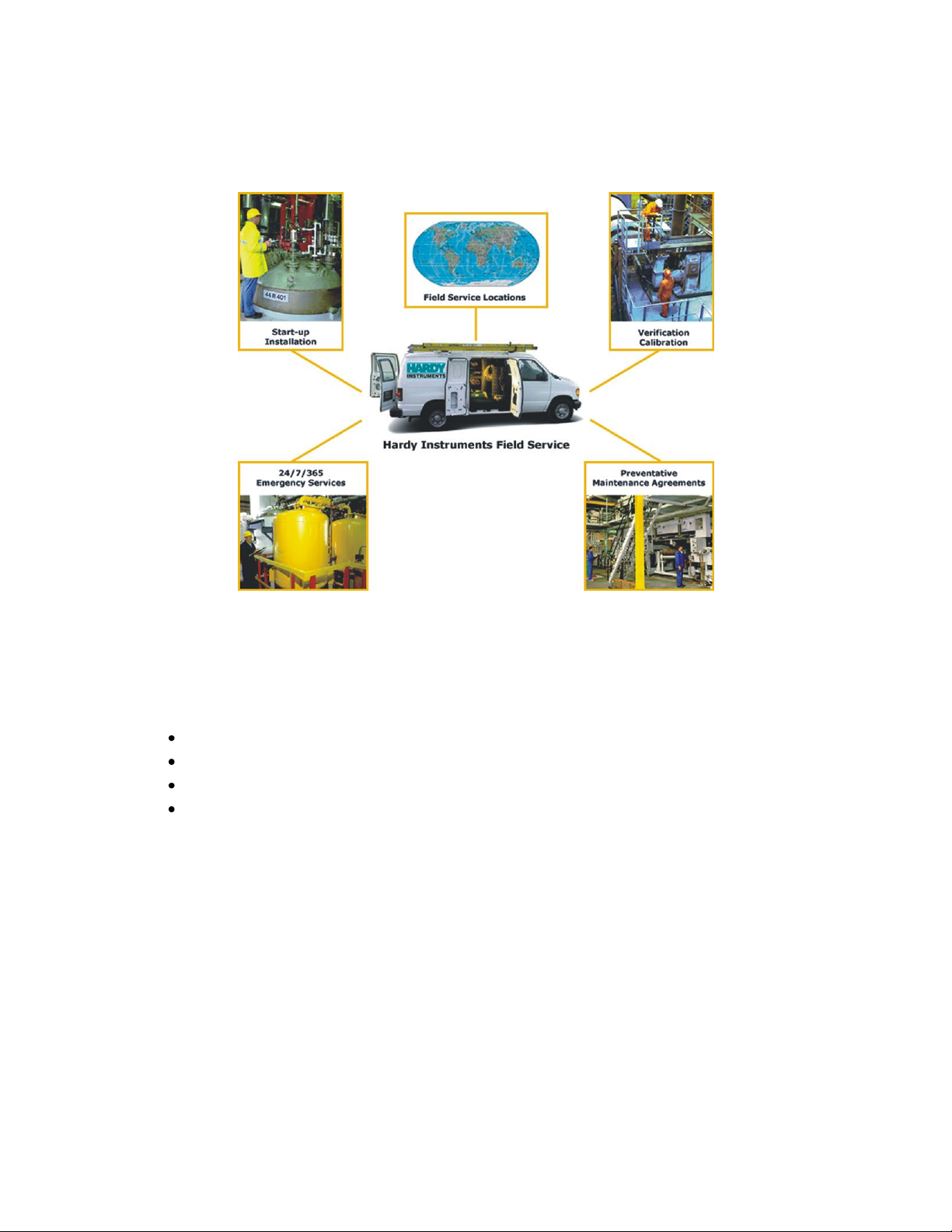
Local Field Service
Hardy has over 200 field technicians in the U.S., and more positioned throughout the world to assist you in
your support needs. We also have factory engineers who will travel to your facility anywhere in the world
to help you solve challenging applications. We're ready to support you with:
Installation and start-up
Routine maintenance and certification
Plant audits and performance measurement
Emergency troubleshooting and repair
To request Emergency Service and Troubleshooting, Start-up, Installation, Calibration, Verification or to
discuss a Maintenance Agreement please call 800-821-5831 (Standard Hours 6:30 AM to 5:00 PM Pacific
Standard Time).
Outside the U.S
Hardy Process Solutions has built a network of support throughout the globe. For specific field service
options available in your area please contact your local sales agent or our U.S. factory at +1 858-292-2710.
Page 3

i
●
●
●
●
●
Contents
Contents
● ● ● ● ●
CONTENTS ........................................................................................................... I
CHAPTER 1 OVERVIEW ..................................................................................... 1
About Hardy Manuals ................................................................................................................................. 1
HI 1756 nDF Overview ................................................................................................................................. 1
Typical Applications ................................................................................................................................... 2
Features and Capabilities ............................................................................................................................. 2
CHAPTER 2 SPECIFICATIONS .......................................................................... 5
Basic Specifications ....................................................................................................................................... 5
General ........................................................................................................................................................ 5
Environmental Requirements ...................................................................................................................... 6
Pending Approvals ...................................................................................................................................... 6
CHAPTER 3 INSTALLATION .............................................................................. 7
Unpacking ...................................................................................................................................................... 7
Installing the HI 1756 nDF ........................................................................................................................... 7
Allen-Bradley ControlLogix Processor or Remote Rack ............................................................................ 7
A ControlLogix Chassis .............................................................................................................................. 7
Removing the Module from the Chassis ..................................................................................................... 8
Installing the Module I/O Connector ........................................................................................................... 8
Load Cell Wiring Diagrams ......................................................................................................................... 9
HI 1756 1DF Valve wiring diagram ............................................................................................................. 9
Hardy HI 215IT Junction Box ................................................................................................................... 10
CHAPTER 4 CONFIGURATION ........................................................................ 11
Power Check ................................................................................................................................................ 11
LEDs ......................................................................................................................................................... 11
Dot Matrix Display .................................................................................................................................... 12
Setting Up Communications ....................................................................................................................... 12
Configuring the HI 1756-nDF Dispenser Filler Module in the RSLogix 5000 for ControlLogix with the
HI 1756-nDF Module Add on Profile ....................................................................................................... 12
Linking the PLC with the HI 1756-nDF Dispenser Filler Control Module ............................................... 15
Overview of Operation ................................................................................................................................ 16
DINT Configuration Parameters used in Flow Rate Control .................................................................... 18
REAL Configuration Parameters used in Flow Rate Control .................................................................... 19
DINT Configuration Parameters used in Auto-Preact ............................................................................... 22
REAL Configuration Parameters used in Auto-Preact .............................................................................. 22
Status Values used in Auto-Preact function .............................................................................................. 23
Assembly Object Instances ......................................................................................................................... 25
First Word – 0: Command Number .......................................................................................................... 27
Page 4

ii
●
●
●
●
●
Contents
Command Return or Error Codes .............................................................................................................. 29
Second and Third Words - 1, 2: Parameter Number and Value ............................................................. 29
DINT Configuration Parameters ............................................................................................................... 29
REAL Configuration Parameters .............................................................................................................. 34
REAL Status Values .................................................................................................................................. 38
Integrated Technician ................................................................................................................................ 40
CIP Messages ............................................................................................................................................ 41
CHAPTER 5 CALIBRATION .............................................................................. 43
Pre-Calibration Procedures ........................................................................................................................ 43
Electrical Check Procedures ...................................................................................................................... 43
Load Cell/Point Input/Output Measurements ............................................................................................ 43
Load Check ............................................................................................................................................... 44
AOP Calibration .......................................................................................................................................... 44
C2 Calibration ............................................................................................................................................. 44
“THE BUTTON” C2 Calibration .............................................................................................................. 45
C2 Calibration Using Ladder Logic .......................................................................................................... 45
Hard Calibration ......................................................................................................................................... 46
Hard Calibration Ladder Logic Example .................................................................................................. 46
CHAPTER 6 TROUBLESHOOTING ............................................................... 47
Disassembly and Reassembly Notes, Warnings and Cautions ................................................................ 47
Weight and Voltage Testing ....................................................................................................................... 47
IT Test ....................................................................................................................................................... 48
General Troubleshooting Flow Chart Index ............................................................................................. 48
A1 - Guidelines for Instabilities on Formerly Operating System .............................................................. 49
B - Guidelines for Instabilities on Formerly Operating Systems (Cont’d) ................................................ 50
B1 - Guidelines for Instabilities on Formerly Operating Systems (Cont’d) .............................................. 51
B1 - Guidelines for Instabilities on Formerly Operating Systems (Cont’d) .............................................. 52
Testing an individual load cell signal output requires an IT Summing Junction box or millivolt meter. .. 53
Use the load cell certificate to verify the millivolt per volt (mV/V) rating: .............................................. 53
G - Calibration Failed ................................................................................................................................ 54
H - Mechanical Inspection ........................................................................................................................ 55
J - Electrical Inspection ............................................................................................................................. 56
K - Load Sharing and Load Sensor Checkout ........................................................................................... 57
Erratic Flow Rates ...................................................................................................................................... 58
System and Load Cell Tests ........................................................................................................................ 58
INTEGRATED TECHNICIAN (IT®) ...................................................................................................... 59
Stability Test ............................................................................................................................................. 60
Weight and Voltage Test ........................................................................................................................... 60
General Policies and Information .............................................................................................................. 60
Warranty .................................................................................................................................................... 61
For Further Information Contact ............................................................................................................... 61
INDEX ................................................................................................................ 62
Page 5

1
●
●
●
●
●
Chapter 1
Chapter 1 Overview
● ● ● ● ●
This manual provides users and service personnel with specifications and procedures for
installing, configuring, operating, maintaining, and troubleshooting the Hardy Process
Solutions HI 1756 nDF Dispenser Filler with WAVERSAVER®, C2®, and
INTEGRATED TECHNICIANTM (IT®) diagnostics.
NOTE WAVERSAVER, C2, and IT are registered trademarks of Hardy Process Solutions, Inc.
To ensure good performance and maximum service life, follow all guidelines described
in this manual. Be sure you understand all cautions, warnings, and safety procedures. If
you find that the information in this manual does not provide the help you need, contact
the HI Customer Service Department at:
Phone: (858) 278-2900
FAX: (858) 278-6700
Web Site: www.hardysolutions.com
Support e-mail address: support@hardysolutions.com
About Hardy Manuals
An overview of each chapter’s contents is listed below:
Chapter One - Provides an overview of HI 1756 nDF capabilities and features
Chapter Two - Provides a overview of HI 1756 nDF specifications
Chapter Three - Describes the steps for installing both the standard and optional HI
1756 nDF equipment, and the HI 215IT series junction box
Chapter Four - Explains how to configure the HI 1756 nDF
Chapter Five - Provides calibration instructions
Chapter Six – Provides troubleshooting procedures for repair of the HI 1756 nDF
HI 1756 nDF Overview
The HI 1756 nDF is a ControlLogix I/O module, which is designed to operate in a local
rack or a remote rack that is connected to the local chassis via a network link.
The module can be inserted and removed under power without disruption of any other
modules in the system (racks). This makes it possible to replace a failed module while
keeping the rest of the system running. Status indicators will be provided on the front of
the module for fault status. A status block will provide information to the processor for
alarming and troubleshooting (IT).
The HI 1756 nDF can be purchased as a single channel (1756 1DF) or dual channel (1756
2DF) module; enabling up to two separate single or multi-cell weight scales to be
monitored at one time. Two relays are assigned to each weigh scale input, and can be
triggered by programmable target weight and preact weight values.
The analog-to-digital converter in the weigh module controller is capable of 8,388,608
counts of resolution which allows the instrument to tolerate large “dead” loads, over
sizing of load cells/sensors, and still have sufficient resolution to provide accurate weight
measurement and control. The analog-to-digital converter can be configured to provide
either 95 or 145 updates per second. The 95 updates per second mode is recommended
Page 6

2
●
●
●
●
●
Chapter 1
for nosier environments while the 145 updates per second mode provides a faster
response time to changes in the flow rate.
The module supports both C2 electronic calibration and hard calibration (i.e., traditional
calibration with weights).
Typical Applications
Dispenser filler control can be used in a variety of material-flow applications.
The 1756 nDF Controller can control up to two ingredients per weigh scale channel, in a
filler mode, using two integrated DC or AC relays which can be independently controlled
automatically through programmable set point values or manually. The setpoint values
can be adjusted throughout the fill cycle, however once a relay is OPENED (external
valve is closed) it cannot be CLOSED again until the next fill cycle is started.
Features and Capabilities
C2® Calibration
Traditional calibration uses certified test weights. C2® Electronic Calibration allows a
scale to be calibrated without the need for test weights. A C2® weighing system consists
of up to eight load cell sensors per channel, a junction box, interconnect cable, and an
instrument with C2® capabilities (e.g., the HI 1756 nDF). Each Hardy Process Solutions
C2-certified load sensor outputs digital information used for calculating the calibration.
When the HI 1756 nDF reads the signals from the load sensors, it calibrates the scale
based on the load sensor’s output plus a user-supplied reference point value (from 0 to
any known weight on the scale).
NOTE C2® is registered trademarks of Hardy Process Solutions Inc.
WAVERSAVER®
When measuring small weight changes, the affects of mechanical vibration and noise
from the feeders and plant environment can introduce substantial interference.
WAVERSAVER factors out vibration, noise, and other interference-related signals from
the load cell so the rate controller can better decipher the actual weight data.
While WAVERSAVER can factor out noise with frequencies as low as 0.25 Hz, five cutoff frequencies can be selected, with higher frequencies providing a faster response time.
The default factory setting is 1 Hz vibration frequency immunity.
Integrated Technician™
The HI 1756 nDF Integrated Technician™ (IT®) is built-in system diagnostics that
makes it possible to diagnose weighing system problems. IT allows the reading of
individual load sensor voltages and weights and isolates individual system components
for quick and easy troubleshooting.
Digital Volt Meter (DVM) - Option
DVM requires the HI 215IT Series Junction Box to monitor mV/V readings for each load
sensor and the total system. When the operator detects a problem, the DVM readings help
to isolate the faulty component. Further, the DVM readings can be used to level a system
and to make corner adjustments to platform scales. Accuracy is +/- 2% or better of full
scale.
NOTE If you do not have the HI 215IT Junction Box connected to the module, the reading is the
total for all load cells on the system.
Page 7
3
●
●
●
●
●
Chapter 1
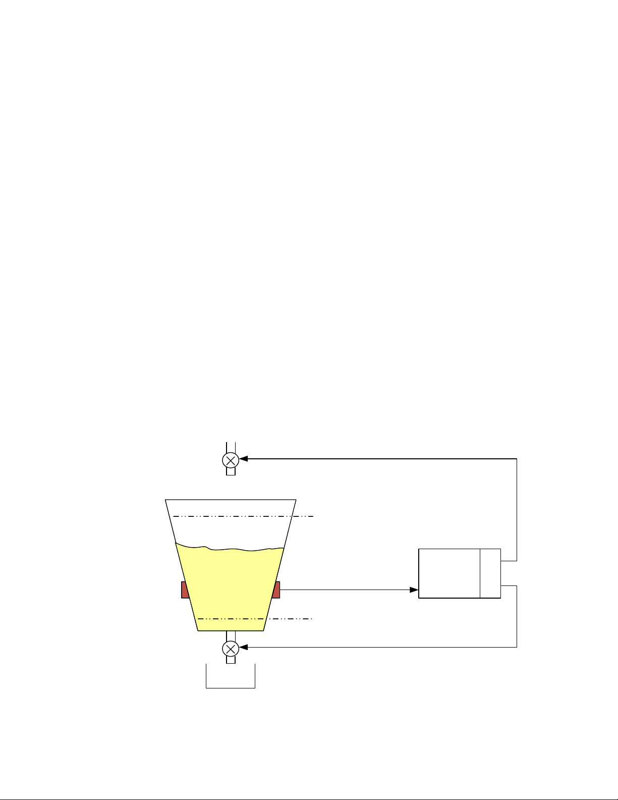
Start Refill Weight
Stop Refill Weight
1756-1DF
Weight value
Dispense Valve Control
RA1
RB1
Refill Valve Control
Weighing System Tests - Optional
This test is used to diagnose drifting or unstable weight reading problems. It requires the
HI 215IT Series Junction Box for full utilization. The ability to read the weight seen by
the individual load sensors allows you to use this test for making cornering, leveling and
load sharing adjustments to the weighing system.
The Weighing System Test provides the following problem detection support:
1. Disconnects the controller and engages an internal reference signal to see if the
problem is inside of the instrument.
2. Disconnects the load sensors and engages an internal (in the junction box)
reference signal to see if the cable between the instrument and the Junction Box
is causing the problem.
3. Reads the weight of each load sensor to see if the load sensor might be causing
the problem.
Automatic or Manual Refill
Automatic refill uses user-selectable refill points to start and stop the refill process
between dispense cycles. Automatic refill is only set for Dispense single speed mode.
The relay B is the default refill relay in single mode and dribble feed in the dual mode. A
command status of -1 will be set when the automatic refill is incorrectly configured.
Automatic refill is not usable in the filler mode as the refill source vessel weight is not
monitored by the HI 1756 nDF.
In the automatic refill mode, if weight at the end of a single speed dispense cycle is equal
to or below the start refill weight parameter value, then the dispense cycle is disabled
and the refill cycle started automatically; once the weight reaches the stop refill weight
parameter value the refill cycle is stopped. Once the refill cycle is complete the dispense
cycle is once again enabled. In this mode relay RA on the weigh scale channel would be
used for the dispense cycle and relay RB on the same weigh scale channel would be used
for the refill cycle.
An Automatic Refill Example
Page 8

4
●
●
●
●
●
Chapter 1
The Manual Refill option allows for manual refill at any time, via the STARTREFILL
command; the refill cycle will automatically stop when the weight reaches the stop refill
weight parameter value. The STOP command will set both relays to their default (OPEN)
state.
The SETRELAY command can also be used to directly control the relay states regardless
of weight value.
In the filler mode the PLC will need to remotely detect the level in the dispensing vessel
and implement a manual refill operation.
Page 9

5
●
●
●
●
●
Chapter 2
Chapter 2 Specifications
● ● ● ● ●
Chapter 2 provides specifications for the HI 1756 nDF Dispenser-Filler and other
equipment that may come with the package. The specifications listed are designed to
assist in the installation, operation and troubleshooting of the instrument. All service
personnel should be familiar with this section before installing or repairing the
instrument.
Basic Specifications
General
Resolution
Internal:1:8,388,608
Input
Up to four 350-ohm Full Wheatstone Bridge, Strain Gauge Load Sensor/Cells (5 volt
excitation) can be connected to each weigh scale channel
Non-Linearity
0.0015% of Full Scale
Common-Mode Rejection
110dB at or below 60 Hz
Common-Mode Voltage Range
2.5VDC maximum (with respect to earth ground)
Backplane Input Voltage
5 VDC and 24 VDC
Backplane Current Load
<1 Amp at 5 VDC
0.0125 Amps at 24 VDC (with 4-350 Ohm Load Cells)
Backplane Power Load
< 5W at 5 VDC
< .3W at 24 VDC with 4-350 Ohm Load Cells
C2 Calibration Input
Isolation from digital section 1000 VDC minimum.
Cable lengths
1000 feet maximum of C2 authorized cable
250 feet maximum of C2 authorized cable (Maximum of 4 load sensors) with IT Junction
box.
Load Cell Excitation
5 VDC +/- 1.15 VDC maximum.
Isolation from digital section 1000 VDC minimum
C2 Calibration Output
Isolation from digital section 1000 VDC minimum
Number of Channels
Page 10

6
●
●
●
●
●
Chapter 2
HI 1756 1DF 1 Weigh Scale Channel
HI 1756 2DF 2 Weigh Scale Channels
Update Rate
95(10.5ms) or 145(6.9ms) Updates per Second
Averages
1-255 User-selectable in Single Increments
WAVERSAVER®
User Selectable
OFF
7.50 Hz
3.50 Hz
1.00 Hz (Default)
0.50 Hz
0.25 Hz
Digital Voltmeter (Integrated Technician – Diagnostic Mode Only)
Accuracy ± 2% of full scale
Relay
Two integrated solid state DC or AC relays per weigh scale channel
Default state of relays will be OPEN (Form A - NO).
For resistive loads only. Cannot mix AC and DC relays on same module.
DC Relay
Capable of switching 5 to 30 VDC
Maximum current rating 3A @ 25oC, 2A @ 40oC, and 1A @ 60oC
Minimum load current 2mA
AC Relay
Capable of switching 24-280 (47-63Hz) VAC
Maximum current rating 0.5A @ 60oC
Minimum load current 70mA
Environmental Requirements
Operating Temperature Range
0 to 60º C (32º F to 140º F)
Temperature Coefficient
Less than 0.005% of full scale per degree C for Cal-LO and Cal-HI reference points
Storage Temperature Range
-40 to 85º C (-40 to 185º F)
Humidity Range
0-90% (non-condensing)
Pending Approvals
UL, CUL, and CE
Page 11
7
●
●
●
●
●
Chapter 3
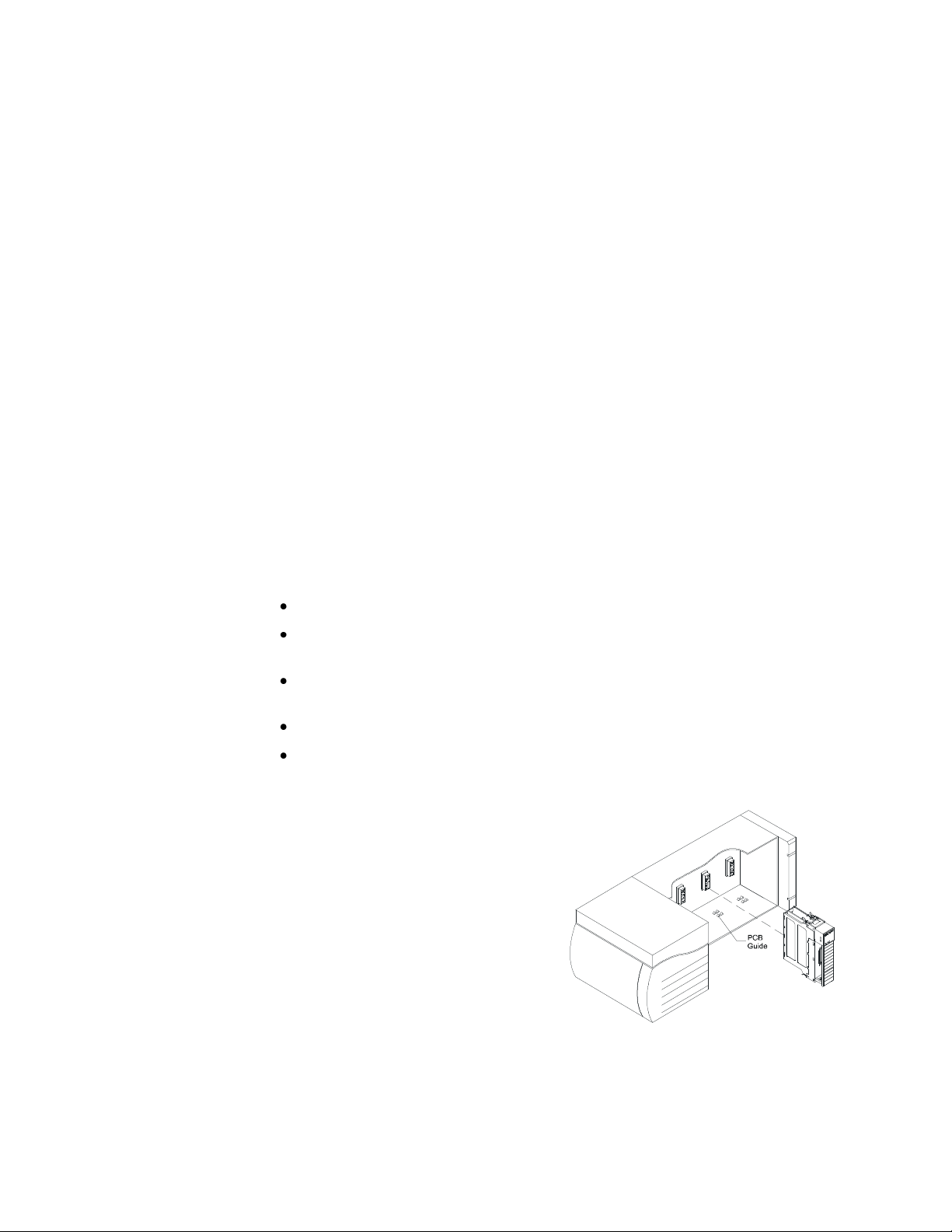
Step 1. Make sure that the module is
oriented correctly for installation.
Step 2. Gently slide the module into the
Chassis.
Step 3. Slide the digital board between the
PCB Guides on the top plate and
bottom plate of the chassis to line up
the module connector with the
backplane connector
Inserting the module
Chapter 3 Installation
● ● ● ● ●
Chapter 3 covers unpacking, cabling, interconnecting, configuring, and installing the
Weigh Scale Module. User and service personnel should read this chapter before
installing or operating the Weigh Scale module.
Unpacking
Step 1. Before signing the packing slip, inspect the packing and contents for damage of
any kind. Report any damage to the carrier company immediately.
Step 2. Verify that everything in the package matches the bill of lading.
Step 3. Write down the Model and Serial number of the module. Store this information
in a convenient location for reference when contacting The Customer Support
Department for parts or service.
Step 4. Be sure to complete the warranty registration on the Hardy web site.
Installing the HI 1756 nDF
Allen-Bradley ControlLogix Processor or Remote Rack
WARNING Electrostatic discharge may damage semiconductor components in the module. DO NOT
TOUCH THE CONNECTOR PINS, and observe the following handling precautions:
Wear an approved wrist-strap grounding device when handling the module.
Touch a grounded object or surface to rid yourself of any electrostatic
discharged prior to handling the module.
Handle the module from the bezel in front away from the connector. Do not
touch the connector pins.
Do not install the module right next to an AC or high voltage DC module.
Route all the load voltage cables away from high voltage cables.
A ControlLogix Chassis
Page 12
8
●
●
●
●
●
Chapter 3
Module release(s)
Module installed in chassis
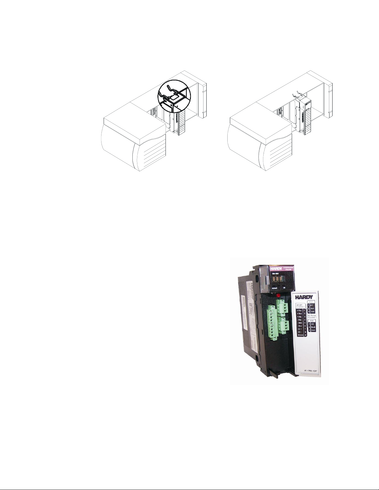
The I/O connector at the front of the module
connects the module to a load sensor, or the HI
215IT Series Junction Box, depending on how
many load sensors are installed in the weighing
system. (See the pin-out diagram below.) A pinout diagram is also located on the inside of the
module door.
Open the module door to access to the I/O
connector.
Step 1. Install the cable and connector so it
allows the module door to be shut.
Step 2. With the plug oriented correctly (See
the pin-out diagram below), plug the I/O male
connector into the I/O connector at the front of
the module.
HI 1756 1DF with door open
Step 4. When the module connector is touching the backplane connector, firmly but
carefully push toward the chassis until the pins are plugged in and the top and
bottom module releases are snapped into place.
Removing the Module from the Chassis
Step 1. Press down on the top and bottom module releases simultaneously until the
module can be pulled away from the chassis. (See Figure above.)
Step 2. Pull the module out of the chassis.
Step 3. Store in a safe, secure location in an anti-static bag or the original enclosure.
Installing the Module I/O Connector
Page 13
9
●
●
●
●
●
Chapter 3
Check to be sure that the connector is completely
plugged in before operating the module.
NOTE Most module-related problems are due to loose
connections. Be sure to check the I/O connection first
in the event you have a problem receiving
information from the load cells or if the relays do not
operate correctly.
Single Channel
Pin 1 Exc+
Pin 2 Sense+
Pin 3 Sig+
Pin 4 Sig-
Pin 5 Sense-
Pin 6 Exc-
Pin 7 C2+
Pin 8 C2-
Pin 9 Shield
Industry standard load cells wiring
Hardy load sensor/c2 wiring
+Exc
-Exc
+Sen
+Sig
-Sig
-Sen
+C2
-C2
Shield
RA1 IP
RA1 OP
RA1 COM
RB1 IP
RB1 OP
RB1 COM
1756-1DF
C2
Shield
Load Cell
(0-24Vdc, 3.5A)
Valve
1
(0-24Vdc, 3.5A)
Valve
2
Control Voltage 2
Control Voltage 1
COM2
COM1
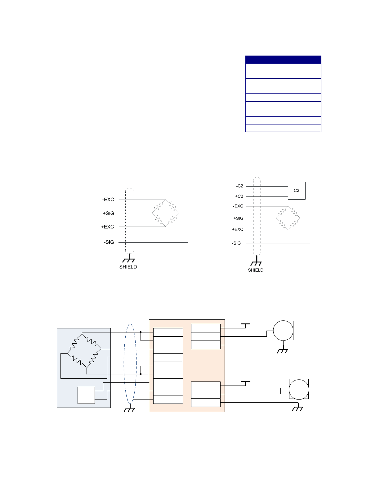
Load Cell Wiring Diagrams
The diagrams below show how Hardy Load Sensor with C2 wiring differs from standard
Load Cell wiring. C2 wiring is required when using a Integrated Technician summing
junction box. The C2 wires are used fro communicating IT and C2 commands.
HI 1756 1DF Valve wiring diagram
Page 14
10
●
●
●
●
●
Chapter 3
L o a d C e l
l
C o n n e c t o r
J
1
1756 1DF
The simple wiring diagram above shows how to connect a single load cell to a single
channel 1756 1DF module. Note, when connecting the 1756 1DF to a junction box, the
sense lines would be connected to +Sen and –Sen Connections in the diagram.
The solid state relays used in the 1756 nDF require a 2mA minimum load. When
switching a light load with a solid state relay across the line, you must look at the rated
dropout current of the load. If it is less than 2mA it may not turn off. The solution is to
put a loading resistor in parallel with the light load, to be sure leakage current is sufficient
to the solid state relay is turned off.
CAUTION: INSTRUMENT POWER AND RELAY WIRES SHOULD BE ROUTED AWAY FROM ALL
OTHER SIGNAL CABLES TO AVOID ELECTRICAL INTERFERENCE.
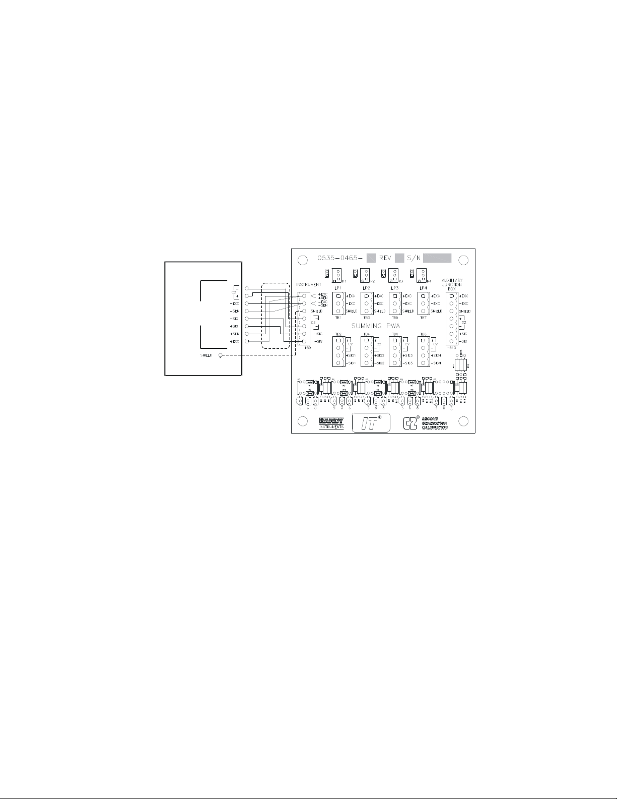
Hardy HI 215IT Junction Box
Hardy HI 215IT Junction Box Wiring Diagram
NOTE When connecting the Hardy HI 215IT Junction Box, you must remove the two factory
installed jumpers on pins 1&2 and on pins 5&6 on the module and install C2 and sense
wires. C2 wires carry the commands for Integrated Technician and the C2 calibration
information.
Page 15
11
●
●
●
●
●
Chapter 4
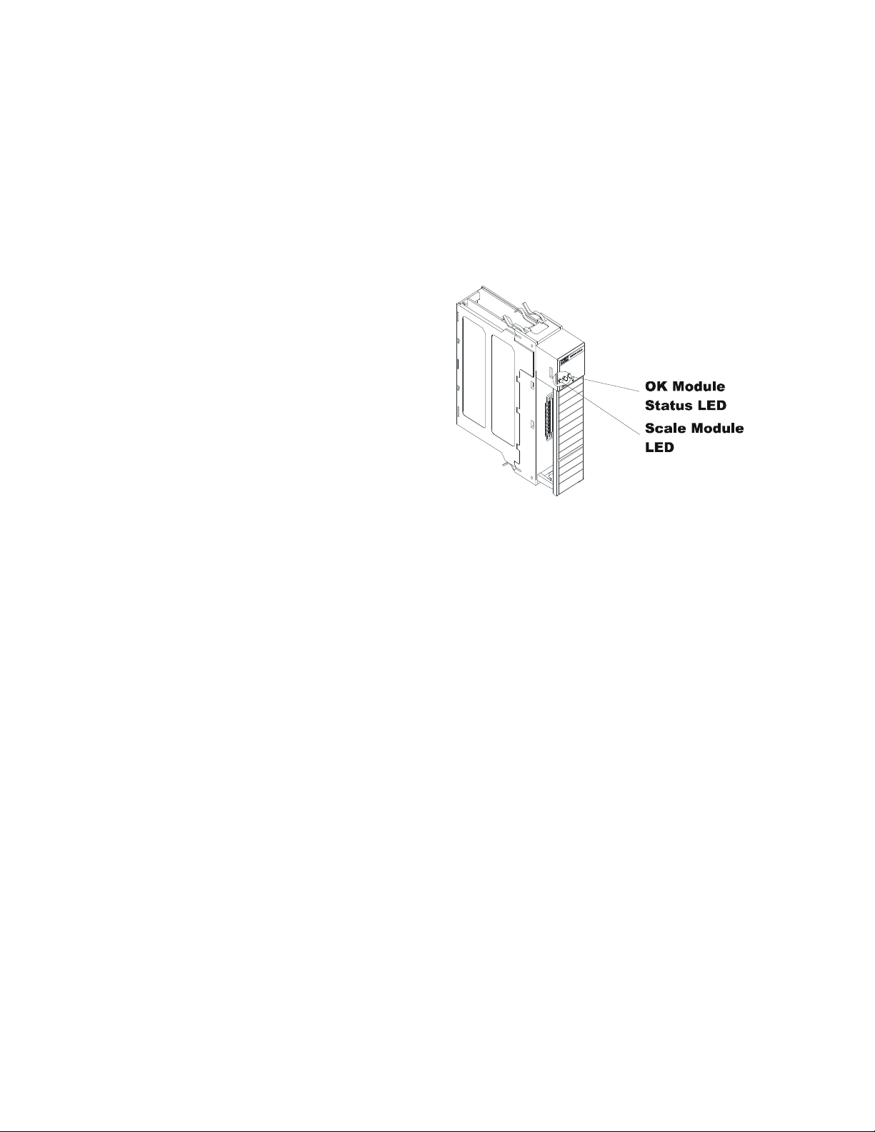
To make or change settings, there
must be power to both the PLC and
the module. Verify that the LEDs
are lit for normal operation.
Module LEDs
Chapter 4 Configuration
● ● ● ● ●
Chapter 4 covers the settings used to prepare the controller for calibration and operation.
The Setup procedures require Allen-Bradley’s RS Logix 5000, Allen-Bradley RSLinx™
or RSLinx™ Lite.
Power Check
LEDs
Scale Data LEDs
Flashing Green Dispenser/Filler is active (on)
Steady Green Running (Normal)
Steady Red Device Failure. Contact HI Customer Support
Flashing Red Read Convert Error.
LED is Off Channel is Inactive
OK Module Status LED
Brief Steady During power up the LED lights Red for about one second.
Flashing Green In Program mode. (Normal)
Steady Green In Run Mode. (Normal)
Steady Red Device Failure. Contact HI Customer Support.
Flashing Red Communication Error.
At power-up, the module runs through an initial self-diagnostic check. If the module does
not have valid calibration data the scale data LED will flash green at a rate of about once
a second.
The door will open to the right revealing two groups of connectors and one red button for
C2 calibration at the “cal low weight” parameter value. The number of pins in the
connector will depend on the number of channel options obtained. The left group of
connectors will be for weigh scale inputs and the group of connectors on the right will be
for relay I/O.
Page 16

12
●
●
●
●
●
Chapter 4
Display
Comment
_
Not Active, OPEN
A
Active, CLOSED
X
Not being used
Dot Matrix Display
Four 3x7 dot matrix displays provide individual status on the relays assigned to each
weigh scale channel.
The three operational states are defined in the following table.
Setting Up Communications
Configuring the HI 1756-nDF Dispenser Filler Module in the RSLogix
5000 for ControlLogix with the HI 1756-nDF Module Add on Profile
To set up communications between the ControlLogix processor and the dispenser/Filler
Control module using the Add on Profile (AOP), you will need to do the following in
RSLogix 5000.
Step 1. Download the AOP files from the Hardy Process Solutions web site,
hardysolutions.com and install.
Note: If a password is requested use hi1756 (all lower case).
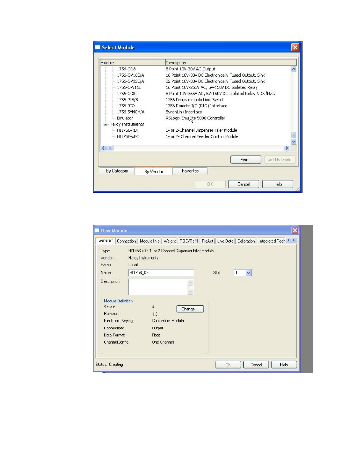
Step 2. Under the project, right click on the I/O Configuration and from the list box
select “New Module”. The “Select Module Type” dialog box appears.
Step 3. Scroll down and find the “Hardy” modules and expand this category. Select the
HI 1756-nDF module and click on the OK button. The module properties dialog
box appears.
Page 17
13
●
●
●
●
●
Chapter 4
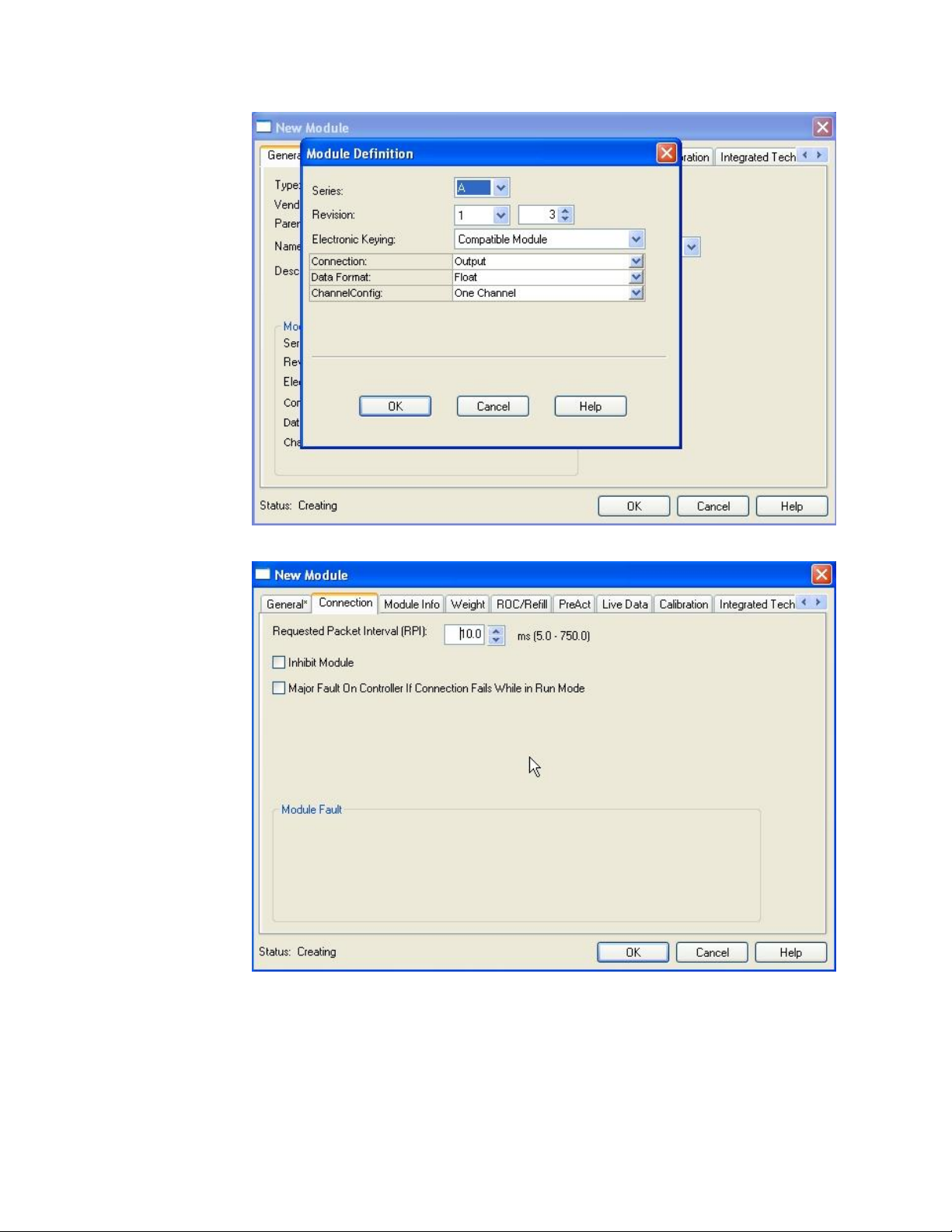
Step 4. Click in the Name text field. Enter a descriptive name for the module. We used
HI1756DF for example. Click in the Description box and enter a description if
desired. Insure the slot selection is correct.
Step 5. If you have a dual channel module, you should click on the “Change” button and
select “Two Channel”.
Page 18
14
●
●
●
●
●
Chapter 4
Step 6. On the Connection tab, set the RPI time to 10.0 ms.
The remaining tabs will allow the user to fill out the parameter settings for the module.
Page 19

15
●
●
●
●
●
Chapter 4
Linking the PLC with the HI 1756-nDF Dispenser Filler Control
Module
To set parameters for the weigh scale module, you must establish communications with a
ControlLogix PLC. Follow the steps below to set up the communication link without
using the AOP. You will need a new or open RS Logix® 5000 project. For instructions,
see your RS LOGIX 5000 manual.
Step 1. Look for a list of folders on the left side of the screen. Scroll to and select the
I/O Config folder, which will open a menu.
Step 2. Select New Module to display a list of modules.
Step 3. Select the Generic 1756 module to open the Module Properties form.
Step 4. Enter the following connection parameters in the appropriate fields:
Name of Module
Description of Module (Optional)
Slot ID
Input Assembly Instance:101 Size = 16
Output Assembly Instance: 100 Size = 16
Configuration Assembly Instance: 102 Size = 200 for a single channel
(1756 1DF) or 400 for a dual channel (1756 2DF)
Step 5. Select DATA REAL from the Comm Format pull-down list.
Step 6. Open the Connection Tab.
Step 7. Set the RPI to 5 milliseconds or greater Do not set this parameter lower than 5
milliseconds.
Step 8. Click Finish.
Page 20
16
●
●
●
●
●
Chapter 4
Weigh Filter
NumAVg
Weight
Conditioning
Weight
Calculation
Weight
Value
Flow Rate
Calculation
Flow Rate Time Base
Weight Unit
Flow Rate
Filter
Flow Rate
Value
Load Cell
Signal
Flow Rate Update Period
Flow Rate Filter
Material
ADC
Weight Update Rate
Current
Flow Rate
Auto_Preact
Calculation
Auto_Preact
stable
capture time
p gain
i gain
frc tolerance
variation
capture
steady period
auto preact config
start wait
fast adjust
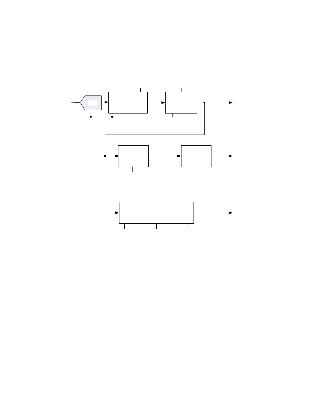
Overview of Operation
The HI 1756 nDF will calculate Gross weight, Net weight, & Flow Rate (FR) outputs
simultaneously, as shown in the simplified block diagram below.
Overview of Weight Calculation
The ADC data can be filtered to reduce short term disturbances caused by system noise,
vibration noise, and local short term disturbances that could affect the weigh
measurement.
The most robust method to reduce these system disturbances is Waversaver®, but this
mode has the longest delay which is directly proportional to the bandwidth selected as the
algorithm requires at least one full cycle of the lowest frequency to be able to remove the
noise and harmonics from the weight measurement. On the other hand the raw data
sample mode provides the fastest response with no additional delay but does not filter out
any noise from the sampled data. As a compromise a low pass filter can be selected to
provide noise shaping across multiple samples centered on the current weigh value; this
mode has a fixed delay of 100mS.
The filter selection will depend upon the environment and the desired response time to
changes in weight.
Simplified block diagram for the 1756-1DF
Page 21
17
●
●
●
●
●
Chapter 4
Weight
Filter
Delay (ms)
Quality Comment
0 0 Poor, no filtering
1
100
Fair, narrow filter window
2
270 – 2000
Excellent, Waversaver® filter selection
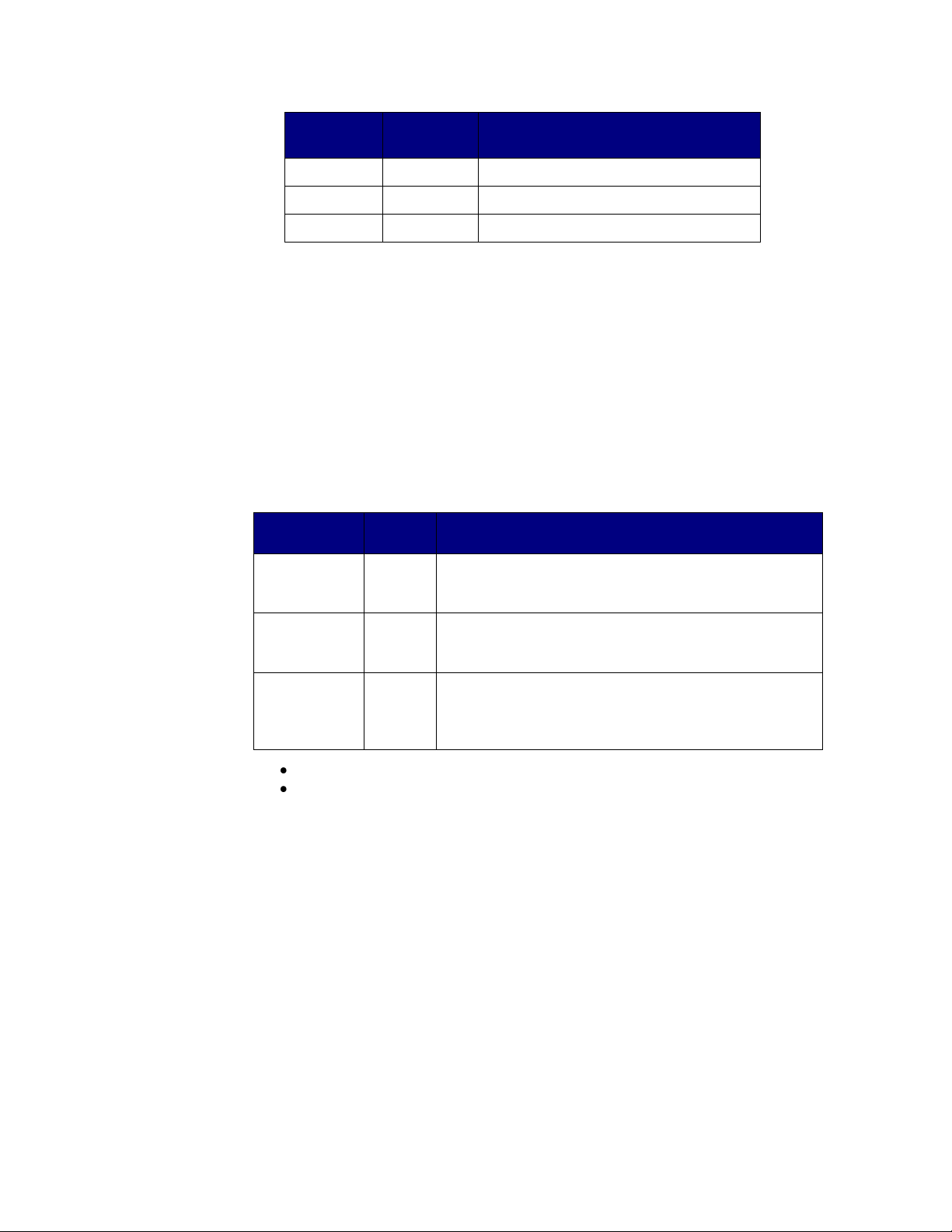
Parameter
Default
Description
steady period
128
Sets the number of samples used to calculate the steady
weight value used in the auto-preact function.
variation
*1
Sets the peak to peak variation in weight values which will
be processed
capture
*2
Sets the peak to peak variation in processed weight values
that will be used to calculate the weight value on the scale
after in flight material has settled.
Note: ADC delay in not included in delay calculation as this delay is
consistent regardless of filter mode selected.
In addition a second filtering stage can be enabled which averages the current and
preceding ADC samples. This is a simple method to remove harmonics from the data
stream without introducing delay into the data path. For example, if NumAverages
parameter is set to 10 (default) and the weight update rate is 100Hz, a frequency notch
will occur every 10Hz in the sampled spectrum. This simple but effective filter is ideal
for removing harmonics at known frequencies within the sampled spectrum.
To calculate the preact value to compensate for in flight material, it is necessary to set
tolerances so that the weight processing algorithm can detect when amount of inflight
material falls within a user specified tolerance over a set number of samples. The
required parameters are shown in the following table. This processing does not add delay
into the signal processing path.
*1: Default value set to 1/2,500 of maximum capacity of the load cell.
*2: Default value set to 1/10,000 of maximum capacity of the load cell
Overview of Flow Rate Control
The default setting for the flow rate will be kilograms per second (kg/sec); however the
time interval will be programmable to also include kilograms per minute (kg/min) and
kilograms per hour (kg/hr) and the weight value can be programmed to be in pounds
enabling lbs/sec, lbs/min, and lbs/hr flow rate to be generated.
The flow rate calculation is a filtering operation tailored to provide an accurate
measurement of the material flow rate over the specified period of time. As the update
period is typically faster than the flow rate unit of time, the HI-1756 nDF will scale the
current calculation to match the programmed flow rate unit of time, albeit hours, minutes,
or seconds.
The time base value sets the number of samples that will be reviewed each time a flow
rate calculation is made.
Page 22

18
●
●
●
●
●
Chapter 4
Parameter
Default
Description
Weight Unit
3
Weight unit selection
Value
Frequency (Hz)
0
Pounds(lb)
1
Ounces(oz)
2
Ton(ton) short ton
3
Kilograms(kg)
4
Grams(g)
5
Metric Tonnes (t) long ton
Flow Rate
Period
0
Flow Rate options
Ref#
FR unit of time
0
seconds
1
minutes
2
hours
Weight Filter
2
The weigh scale data used in the weight calculation can
be derived from one of three filters. The selection is
based on a compromise between the response time
required and the inherent noise within the measured
value.
FILT
Function
0
Raw ADC data samples
1
Low Pass filter
2
Waversaver output data
Material
0
The material texture can cause fluctuations in the
instantaneous weight readings. To compensate for these
periodic fluctuations set to 0 for liquids and fine
materials and 1 for coarse materials.
The flow rate is affected by the composition of the material, for example liquids will
provide a linear flow rate as they are dispensed compared to “lumpy” material which due
to product binding and asymmetric shape will cause short term disturbances in the weigh
reading and subsequent flow rate calculations.
To provide a reliable flow rate reading with a range of materials the following four flows
rate filters are provided, see the “flow Rate Filter” parameter in the table below.
Parameters for configuring the flow rate calculation are detailed in the following tables:
DINT Configuration Parameters used in Flow Rate Control
Page 23

19
●
●
●
●
●
Chapter 4
Parameter
Default
Description
Flow Rate
Filter
1
The weight data used in the flow rate calculation can be
derived from one of four filters. The selection is based
on a compromise between the response time required
and the inherent noise within the measured value.
FRF
Quality Comment
0
No suppression of flow rate fluctuations
caused by system noise, fast response time to
step change in flow rate
1
Adaptive Flow Rate Filter (default)
Very good at suppressing flow rate
fluctuations caused by system noise, and has a
fast response time to step change in flow rate
2
Long Term Non-Adaptive Filter
Excellent at suppressing flow rate fluctuations
caused by system noise, but has a long
response time to step changes in flow rate
3
Short Term Non-Adaptive Filter
Very Good at suppressing flow rate
fluctuations caused by system noise, and has a
short response time to step changes in flow
rate
Parameter
Default
Description
Flow Rate
Timebase
4.0
Period of time over which changes in weight are used to
calculate the flow rate. The smallest increment is 100ms.
Unit of time is in seconds.
REAL Configuration Parameters used in Flow Rate Control
Overview of Relay Operation
After power up all relay outputs are in the OPEN state, which is assumed to indicate that
the external valves are CLOSED, and will remain in the OPEN state until the unit is
programmed via the output table.
There are two programmable set points per weigh scale channel; each set point is
associated with a relay output. As the 1756 nDF can be a single or dual channel and the
operation of each channel is independent, the relays, target weight and preact values used
on each channel will be referenced as relay RA, target TA, preact PA, relay RB, target
TB, and preact PB.
The HI 1756 nDF implements a change in weight (CIW) algorithm, which requires that
the external system controls if the weight will increase (fill) or decrease (dispense) and
the HI 1756 nDF simply treats the net weight as an absolute value with respect to the zero
Page 24

20
●
●
●
●
●
Chapter 4
Ref#
Relay Mode
Description of Relay Operation
0
Single Relay
Operation
Relay RA is set to the CLOSED state at the beginning
of the fill cycle. Relay RB is held in the OPEN state.
When the absolute net weight value is greater than or
equal to the SPA value relay RA is set to the OPEN
state.
RB is the refill relay.
SPA = target weight TA – preact PA
SPB = 0.0
point. The preact value can be positive or negative, to compensate for in flight material,
to ensure the set point operates at the correct absolute net weight value.
The relay’s initial state, OPEN or CLOSED, is determined by mode of operation. The
dynamic state of the relay during a fill cycle depends on the comparison of the current net
weight to the calculated set point value. The set point value is based on three parameters
the target weight, the preact weight, and the mode of operation. These parameters are
defined below:
1. The “target weight”
The target weight is a floating point number indicating the nominal weight value that
should OPEN or CLOSE the relay depending on the mode of operation.
Regardless of mode it is recommended that each fill cycle should start with a TARE
command to set the net weight to zero.
2. The “preact” value
In order to compensate for delays caused by sensor reaction time or in flight material,
there is a preact parameter. The preact value is subtracted from the target weight so
negative preact values will increase the set point weight value with respect to the target
weight value, and positive values will decrease the set point weight value with respect to
the target weight value.
3. The “mode of operation”
In the following description when the relay is OPEN the external valve will be CLOSED,
and when the relay is CLOSED the external valve will be OPEN.
The initial state of each relay and the set point calculation depends upon the mode of
operation. Once a relay has been closed it will not be opened until the next start or restart
of a fill cycle.
The sequential mode is defined as the two relays working sequentially; with relay RA
being active before relay RB. In this mode the two relays cannot be CLOSED at the same
time. This mode could be used to select between two different flow rates into one hopper.
The parallel mode enables each relay to operate independently enabling two feeders at
different speeds to be used to fill a single hopper with the same ingredient.
The different modes of operation, for each weigh scale input, are detailed in the following
table; where the Ref# value refers to the mode value used to select the desired mode of
operation.
Page 25

21
●
●
●
●
●
Chapter 4
Ref#
Relay Mode
Description of Relay Operation
1
Sequential Relay
Operation
Relay RA is set to the CLOSED state, and relay RB
set to the OPEN state at the beginning of the fill
cycle. When the absolute net weight value is greater
than or equal to the set point SPA relay RA is OPEN
and relay RB is CLOSED, when the absolute net
weight value is greater than or equal to set point SPB
both relays are OPEN.
Automatic refill not allowed.
SPA = target weight TA – preact PA
SPB = target weight TB – preact PB
2
Parallel Relay
Operation
[Default Mode of Operation for each weigh scale]
Relay RA and relay RB are both set to the CLOSED
state at the beginning of the fill cycle. When the
absolute net weight value is greater or equal to set
point SPA relay RA is OPEN or when the absolute
net weight value is greater or equal to set point SPB
relay RB is OPEN.
Automatic refill not allowed.
SPA = target weight TA – preact PA
SPB = target weight TB – preact PB
2 Speed (Fast/Slow) Mode Considerations
The 1756-nDF can be purchased with two relays per weigh scale channel. The
architecture can be configured so both relays start at the same time (simultaneous feed)
and have different target weights so the “fast” feed is closed before the “slow” feed; or
the two relays can start sequentially (sequential feed) with the “fast” relay (relay A) being
closed when it reaches its target weight and the ‘slow” relay (relay B) opening as soon as
the “fast” relay is closed. Automatic refill not allowed.
In both situations the “fast” relay will never see a stable weight on the scale before the
“slow” relay allows additional material onto the scale. Therefore the “fast” relay will be
treated as a coarse adjustment and will be set to provide a maximum percentage of the
final target weight value, and the auto-preact algorithm will run only on the slow relay to
provide the accurate final dispense cycle to reach the desired target weight.
When setting up the process for the first time the “fast” relay should be run on its own
with the “slow” relay initially disabled; the target weight for the “fast” relay will be set
by running several test dispense cycles. Once the “fast” relay target is set, the slow relay
will be enabled and tests repeated to verify that the vessel does not overfill. If this occurs,
one of two actions can occur:
1. If the auto-preact is at zero or below the “fast adjust” percentage of the target
weight then the fast relay target has been programmed too high. If the “fast
adjust” value is not 0.0% then the target weight set for the “fast” relay will be
reduced by the percentage programmed into the “fast adjust” parameter and the
auto-preact reduced by the same percentage or reset to zero if the residual value
in the auto-preact output is below the “fast adjust” percentage times the target
weight value. This repeats until the unit hits the desired target weight.
2. If the “fast adjust” bit is set 0.0%, then the control system is expected to monitor
the error between the final weight and the desired target weight and should
reduce the fast relays target value. Any change in the fast relay target value
resets the auto-preact value to zero.
Page 26

22
●
●
●
●
●
Chapter 4
Parameter
Default
Description
capture
averages
3
Sets the number of fill/dispense cycles to average the target
error values and flow rate values to provide the auto_preact
value.
auto preact
enable
0
Selects between the internally calculated auto-preact value
and the external preact value in the output table.
Parameter
Default
Description
start wait
2.0
Period of time that the flow rate is ignored in the autopreact calculation
update time
2.0
Period of time after the setpoint value has been reached that
a new weight input can be taken to update the auto-preact
function.
stable
1.0
The maximum peak to peak percentage difference in flow
rate used to detect a stable flow rate.
Overview of Auto-Preact Function
The auto_preact function predicts the required preact weight to ensure that the weight on
the scale at the end of a fill cycle is equal to the desired target weight, after all the inflight
material has cleared the physical pathways and settled on to the scale. The setpoint
weight is the weight at which the relay is closed, and is calculated by subtracting the
preact weight from the desired target weight.
Setpoint weight = target weight – auto_preact weight
At the beginning of the fill cycle the material flow rate is not linear and the start wait
parameter is used to ignore the flow rate during this time. Once the calculated setpoint
has been reached the relay will close the valve and any in flight material will continue to
accumulate on the scale for a short period of time. The update time parameter is used to
set the predicted time for the inflight material to settle onto the scale so a reliable weight
reading can be taken.
This weight value is used in the auto-preact function to continually modify the setpoint
value so the correct target weight is reached.
The auto-preact function combines a proportional plus integral filter based on historical
differences between the target weight and the weight measured on the scale at the end of
each fill cycle; and a predictive function based on the current flow rate.
The following parameters are used to configure the auto-preact function.
DINT Configuration Parameters used in Auto-Preact
REAL Configuration Parameters used in Auto-Preact
Page 27

23
●
●
●
●
●
Chapter 4
Parameter
Default
Description
p gain
0.05
Proportional error term gain value. Additional percentage
of the error added to the amount of correction the module is
making.
i gain
0.65
Integral error term gain value. The percentage of the error
being applied to the auto preact.
frc tolerance
2.0
The minimum peak to peak percentage difference in flow
rate used to detect a stable flow rate. Values below this are
ignored
fast adjust
1.0
If the channel is being used in a simultaneous or sequential
feed mode this sets the percentage of target weight that can
be adjusted on the fast channel if the final measured weight
exceeds the target weight.
Parameter
Description
fast setpoint
time
Actual time from the start of the fill cycle to when the relay on the fast
channel changes state.
slow setpoint
time
Actual time from the start of the fill cycle to when the relay on the slow
channel changes state.
stable time
Time from the start of the fill cycle to the flow rate becoming stable.
Unit of time is in seconds.
steady time
Time from when the target weight is reached (relay triggered) to when
the weight first remains within the capture tolerance for the
programmed number of steady periods.
Unit of time is in seconds.
not stable
A value of ONE indicates that the flow rate did not become stable
during the fill cycle; otherwise this status value is ZERO.
not steady
A value of ONE indicates that the weight did not remain within the
capture tolerance on the scale for the specified number of update
periods, update time, before the capture time was reached; otherwise
this status value is ZERO.
Status Values used in Auto-Preact function
Use of Auto-Preact Status Values
The minimum time to complete an auto_preact cycle is the sum of the slow setpoint time
and capture time values. The slow setpoint time value is the time from the start of the fill
Page 28

24
●
●
●
●
●
Chapter 4
cycle to when the relay changes state, and the capture time is the time from when the
relay changes state to when a weight value is taken (assumed to be available) to update
the auto_preact function. The following status values help to ensure the system timing is
configured correctly. A full picture of the cycle can be calculated by externally
monitoring the time from the start of the fill cycle to when the cycle ends.
Flow Rate Status
The flow rate compensation portion of the algorithm requires a constant, stable, flow rate
to be able to calculate the required value to compensate for in-flight material after the
relay changes state. If the not stable status value is a one, then the flow rate never became
stable before the relay changed state. This could be caused by one of the following
reasons:
1. The stable tolerance is too tight and the material is unable to meet the specified
percentage variation during the fill cycle.
2. The start wait value is too long and the period left to calculate a stable flow is
too short. This can be verified by reading the stable time and slow setpoint time
values. If the stable time is shorter than the start wait period, and is also less than
the setpoint time then the start wait time needs to be adjusted to provide at least
2 timebase periods between the measured stable time and slow setpoint time
values. If the slow setpoint time is less than the stable time then either the stable
tolerance or the material flow rate needs to be adjusted.
3. The flow rate for numerous reasons was changing throughout the fill cycle. This
may be by design and once identified the user can set the frc tolerance parameter
to zero, to disable this portion of the algorithm.
If the not stable status value is a zero, then the slow setpoint time provides a time
reference for stable time value, if the stable time value is multiple timebase periods long,
then adjustments to the flow rate could be considered to increase throughput.
Auto_preact Status
The programmed capture time value represents the time from when the relay state is
changed to when a weight value on the scale can be taken and used to adjust the
auto_preact function.
If the AP_NOT_STEADY status is a one, then the weight did not remain within the
capture tolerance on the scale for the specified steady period before the update time,
programmed time from relay changing state, was reached. To determine possible causes,
the programmed update time should be compared to the steady time status value which
represents the time from when the relay changes state to the first time the weight on the
scale remains within the capture tolerance for the programmed steady period. If the
update time is less than the steady time status duration, then either the update time needs
to be increased so that it exceeds the steady time status duration by at least 0.3 seconds to
allow a stable weight value to be calculated; or the update time needs to be increased so a
reliable weight value is available sooner. While the not steady status is a one, the
auto_preact value is not being updated. When adjusting the update time the auto_preact
values should be reset.
If the update time is greater than the steady time and the not steady value is zero, then the
system will stabilize and the correct auto_preact value will be generated to optimize the
process.
Page 29

25
●
●
●
●
●
Chapter 4
Input table
offset
Content
0
Command (echoes the command given in the Output Table. See below)
1
Command Status (see below)
2
Parameter value, in read and write commands
3
Target Value for relay A (TA)
4
Gross weight
5
Net weight
6
Rate of change
7
STATUSWORD
Input table
offset
Content
8
Command (echoes the command given in the Output Table. See below)
9
Command Status (see below)
10
Parameter value, in read and write commands
11
Target Value for relay A (TA)
12
Gross weight
13
Net weight
14
Rate of change
15
STATUSWORD
Assembly Object Instances
1. Input Assembly (from 1756 nDF to PLC).
An area where the 1756 nDF module writes its data such as Net, Gross, FR to the PLC.
The input assembly is an array of 16 floats, with 8 devoted to the 1st channel and the next
8 devoted to the 2nd channel.
The rate of change and the gross and net weights are always visible in the input table, for
each weigh scale.
Input Assembly for Weigh Scale 1
Input Assembly for Weigh Scale 2 (for HI 1756 2DF only)
2. Output Assembly (from PLC to 1756 nDF)
Dedicated area where PLC writes parameters to the 1756 nDF; these values are read by
the 1756 nDF as scheduled by the RPI. The output assembly defaults to an array of floats.
The output table consists of 16 float values, of which the first 8 float values apply to the
1st channel, and the next 8 float values apply to the 2nd channel.
The first float value of the 8 is the “command” value. The interpretation of the next 7
values depends on the command being given.
Default Output Table Description
These commands are zero, tare, write nonvolatile, reload nonvolatile, cal low, cal high,
C2 cal. These commands do not require any of the 7 other float values. These commands
will use the default output table format.
Page 30

26
●
●
●
●
●
Chapter 4
Output table
offset
Content
0
Command
1
Parameter Number (used by read and write commands)
2
Parameter Value (used by write command and set relay command)
3
*spare*
4 5 6 7
Output table
offset
Content
8
Command
9
Parameter Number (used by read and write commands)
10
Parameter Value (used by write command and set relay command)
11
*spare*
12 13 14 15
Default output table formats
Output Assembly for Weigh Scale 1
Output Assembly for Weigh Scale 2 (for HI 1756 2DF only)
Commands to the PLC related to weigh scale 2, input table offset 8 – 15, are only valid
for HI 1756 2DF modules. For the HI 1756 1DF modules this portion of the input table
will be set and held in its default NOCMD state.
Page 31

27
●
●
●
●
●
Chapter 4
command
Number
description
NOCMD
0.0
No command
STARTANDTARE
1.0
This command causes an automatic TARE of the weigh
scale, sets the relays based on the mode of operation, and
calculates the two set points for relay RA and relay RB
before starting the fill cycle.
Relay Mode
Description
0
Single Relay Mode
1
Sequential Relay Operation
2
Parallel Relay Operation
See “Overview of Relay Operation” for a detailed
description on the different modes of operation.
STARTNOTARE
2.0
This command sets the relays based on the mode of
operation and updates the two set points for both relay RA
and relay RB before continuing to run fill cycle.
The RESTART command does not cause an automatic
TARE of the weigh scale.
Relay Mode
Description
0
Single Relay Mode
1
Sequential Relay Operation
2
Parallel Relay Operation
See “Overview of Relay Operation” for a detailed
description on the different modes of operation.
SET**
3.0
The SET command updates the two set points for relay
RA and relay RB while continuing to run the fill cycle.
The SET command does not cause an automatic TARE of
the weigh scale and does not set the relays based on the
mode of operation. This is used to change the target and
preact values only.
** Repeatable Command
STOP
4.0
The relays are set to their default OPEN state, and the unit
continues to monitor the weight readings but ignores
weight readings to ensure relays remain OPEN.
First Word – 0: Command Number
The default output table enables single parameters and functions to be modified.
The majority of the commands are intended to be used once and require a NOCMD or a
different command to be sent if the same command is to be repeated. However, there are
special function commands which can be repeated and each time the command is read the
appropriate action is taken. These special commands are denoted using a “**” in the
following table. For example the SET command enables the user to continually adjust the
target weight throughout a fill or dispense cycle.
The first word in the output table is a command, the possible commands are:
Page 32

28
●
●
●
●
●
Chapter 4
command
Number
description
SETRELAY**
7.0
Default setting is 0, both relays OPEN
Manual mode for testing relay operation.
0 = both relays RB and RA are OPEN
1 = relay RB is OPEN, and relay RA is CLOSED
2 = relay RB is CLOSED, and relay RA is OPEN
3 = both relays RB and RA are CLOSED
The manual relay setting can be overridden by the
STARTANDTARE and the STARTNOTARE commands.
WARNING: Forcing the relay may cause damage or
personal injury. Make absolutely sure that you know
what the relay is connected to before activating.
** Repeatable Command
RELOADNV
16.0
Reload Non-Volatile
Recall all parameters from non volatile memory.
WRITENNV
17.0
Write Non-Volatile
Save all parameters to non volatile memory.
STARTREFILL
18.0
Starts a manual refill cycle
TARECMD
98.0
TARE: zero the net weight
ZEROCMD
99.0
Zero the gross weight
CALLOWCMD
100.0
Hard calibration, low step.
CALHIGHCMD
101.0
Hard calibration, high step.
C2CALCMD
102.0
C2 calibration.
WRITEPARAM
103.0
Write a single parameter.
To write a single parameter, send the command 103.0.
Specify the parameter to be changed by putting the
parameter number in float number 1, and put the new
parameter value in float number 2 of the output table.
READPARAM**
105.0
Read a single parameter.
To read a single parameter, send the command 105.0.
Specify the parameter to read by putting the parameter
number in float number 1.
The parameter value will appear in word 2 of the input
table.
** Repeatable Command
RESETFR
112.0
Clear all old data from the flow rate (FR) weight buffer.
This has the effect of zeroing the flow rate value.
RESETAPCMD
113.0
Reset Auto Preact Command
Resets all stored values in the auto preact function to their
factory default values.
SETDEFAULT
148.0
Replaces all parameter values with the factory default
parameters values.
Page 33

29
●
●
●
●
●
Chapter 4
return codes
#Value
description
SUCCESS
0.0
Pass
NOTALLOWED
-1.0
Bad state for command, tried to run to start
a cycle while refilling or trying to refill
while running a dispense/fill cycle.
OUTOFTOLERANCE
-3.0
Out of tolerance
INDEXOUTOFRANGE
-4.0
Out of Range
NOSUCHCMD
-5.0
Command bad
C2FAILNODEVS
-6.0
No C2 devices
C2FAILCAPEQ
-7.0
Failure, C2 capacities not equal
HARDCALFAILCOUNTS
-8.0
Fails, too few ADC counts between high low
NOSUCHPARAM
-9.0
Parameter ID incorrect
Parameter
Name
Parameter
Number
Parameter
Default
Description
Channel Active
1.0 1 Boolean, 1 = ON, 0 = OFF
Weight Units
2.0 3
Value
Frequency (Hz)
0
Pounds(lb)
1
Ounces(oz)
2
Ton(ton) short ton
3
Kilograms(kg)
4
Grams(g)
5
Metric Tonnes (t) long ton
NumAverages
3.0
10
1 -255
Averages the current sample and previous
N samples to provide the current weight
value.
Command Return or Error Codes
Commands always return the command word and command status. The command status
word may include the following codes:
Second and Third Words - 1, 2: Parameter Number and Value
The second and third words in the output table, Parameter Number and Parameter Value,
are used by the WRITEPARAM command. For details see the Parameter Table below.
Expanded descriptions are listed below the table by parameter number.
Notes When set by a command, all parameters are saved to non-volatile memory. The scale
calibrations are saved automatically when completed successfully
DINT Configuration Parameters
Page 34

30
●
●
●
●
●
Chapter 4
Parameter
Name
Parameter
Number
Parameter
Default
Description
Waversaver
4.0 3 Waversaver Options
Ref#
Frequency (Hz)
0
OFF
1
7.50
2
3.50
3
1.00
4
0.50
5
0.25
Zero Track
enable
5.0 0 Enables the auto zero tolerance function
when 1.
Weight Filter
6.0 2 Weight filter selections
See Overview of Weight Calculation for
selection details.
Ref#
Filter
0
Raw ADC data samples
1
Filtered data samples
2
Waversaver output data
Refill mode
7.0 0 Setting to 1 the automatic refill mode is
enabled and the unit automatically starts a
refill cycle if the next dispense cycle will
lower the weight below the programmed
start refill weight value. The automatic
refill cycle is stopped when the weight
reaches the programmed stop refill weight
value. This is only available in single relay
mode.
When set to 0 the manual refill mode is
enabled and a STARTREFILL command is
required to start the refill cycle.
Weight Update
Rate
8.0 0 Sets the rate at which weight readings are
taken. Set to 0 for 145Hz mode and to 1 for
95Hz mode.
Material
9.0 0 To compensate for material flow rate, set
to 0 for liquids or fine materials and 1 for
coarse or “lumpy” materials.
Flow Rate
filter
10.0
1
Flow rate filter.
See Overview of Flow Rate Calculation
for selection details.
Ref#
Filter
0
Raw ADC data samples
1
Adaptive running avg
2
Short term running avg
3
Long term running avg
Page 35

31
●
●
●
●
●
Chapter 4
Parameter
Name
Parameter
Number
Parameter
Default
Description
Flow Rate
Units
11.0
0
Flow Rate options
Ref#
FR unit of time
0
seconds
1
minutes
2
hours
Flow Rate
Period
12.0
0
Used to set when the flow rate calculation
is active. When set to 0 (default), the flow
rate calculation continuously runs, and
when set to 1 the flow rate calculation is
run only during a fill cycle.
steady period
13.0
128
When this value is set to zero the steady
weight algorithm is bypassed and the
weight data value is used directly.
The steady weight algorithm is enabled
when a non-zero value is entered. The nonzero value sets the maximum period used
to generate the steady weight output.
The valid array sizes are 16, 32, 64, and
128 (default).
auto preact
enable
14.0
0
Configures the auto preact function.
When set to 0 (default) the auto_preact is
disabled and the preact value must be
entered through the output table.
If this value is set to 1the auto_preact
function is enabled and the preact value
from the output table is ignored; and any
changes to the target weight during a feed
cycle are also ignored. This ensures that
the auto_preact can converge towards a
fixed target weight.
Any transition to 0 causes the current state
of the auto_preact function to be held. If
the auto_preact is not reset through the
command interface, and this value is set
high the auto_preact function continues as
if there was no interruption. It is therefore
strongly recommended that this value is
only changed between filler/dispense
cycles.
Page 36

32
●
●
●
●
●
Chapter 4
Parameter
Name
Parameter
Number
Parameter
Default
Description
capture
averages
15.0
3
This sets the number of fill/dispense cycles
to average the target error values and flow
rate values to provide the auto_preact
value.
The minimum value = 1, and the maximum
value = 100
Parameter 1 Channel Active
Enables or disables the weigh channel.
Parameter 2 Weight Units (Unit of Measure)
The Unit parameter sets the scale and related displays to one of the following options:
0: Pounds (lb)
1: Ounces (oz)
2: Ton (ton) short ton
3: Kilograms (kg) - Default
4: Grams (g)
5: Metric Tonnes (t) long ton
Range: LB, OZ, TON, KG, G, T (default Kg)
Note The weigh scale module does not need to be recalibrated after changing the metric value.
Parameter 3 NumAverages
This is the number of samples to average when determining a value to reduce the effect
of material impact and/or vibration as material moves on and off the scale. The
dispenser/filler takes 95 or 145 readings per second. If you average enough weight
readings, the weight loss or gain remains smooth and the displayed value shows little or
no fluctuation, although it is actually recalculated (by sliding average) with each reading.
If a weight reading fluctuates too much, increase the number of readings in the average,
but for applications that require a very quick weight reading, do not set this value too
high.
The averaging parameter is most often set when using any device that outputs an erratic
signal (e.g. a flow meter). Using the averaging function comes at the expense of response
time. A setting of one average takes 10 milliseconds at 95sps or 6.67milliseconds at
145sps; or at a setting of 95 the average takes 1 second at 95sps or 0.67 seconds at
145sps. The averaging function is a running average, where the input signals are totaled
and the total is divided by the averaging number. The instrument reads one new signal
plus the last number of averages signals and repeats the averaging process again.
For example: With a setting of 20 averages, the instrument reads the 20 most current
input signals, totals the signals, divides by 20, drops the oldest one, reads one new signal
along with 19 old readings, totals the signals, divides by 20, drops the oldest one, etc.
The NumAverages filter is included in all weight filter modes.
Range: 1-255 (default 1)
See also WAVERSAVER for information on filtering unstable weight readings.
Page 37

33
●
●
●
●
●
Chapter 4
Parameter 4 Waversaver
Chapter one provides a detailed description of WAVERSAVER’s function and purpose.
In short, WAVERSAVER helps to mitigate the effects of vibratory forces, allowing the
HI 1756 nDF to distinguish between actual weight data and mechanical noise in the
signals the load cell sends. WAVERSAVER can be configured to ignore noise with
frequencies as low as 0.25 Hz. High values allow faster readings, while the lower values
raise the degree of filtration. 7.5 Hz provides the least vibration immunity with the fastest
response time. 0.25 Hz provides the most vibration immunity with the slowest response
time. The function is user selectable and can be turned off. Waversaver is not used when
the Weight filter is set to RAW, or Low pass filter mode.
Range: OFF, 7.50 Hz, 3.50 Hz, 1.00 Hz (Default), 0.50 Hz, 0.25 Hz
Parameter 5 Zero Track enable
Enables the auto zero tolerance function
Parameter 6 Weight filter
Selects the filter used after the analog to digital conversion stage to remove noise and
harmonics from the weight value.
Parameter 7 Refill mode
This is only available in the single relay mode of operation. Relay B is used for the refill
relay.
Enables the automatic refill mode so the unit automatically starts a refill cycle if the next
dispense cycle will lower the weight below the programmed start refill weight value. The
automatic refill cycle is stopped when the weight reaches the programmed stop refill
weight value. The STOP command will set both relays to their default (OPEN) state.
In the manual refill mode a STARTREFILL command is required to start the refill cycle,
however the refill cycle will automatically stop when the weight reaches the programmed
stop refill weight value.
In automatic or manual mode the STOP command will set both relays to their default
(OPEN) state.
Parameter 8 Weight Update Rate
This parameter sets the update rate of the analog to digital converter, and any subsequent
weight filtering calculations.
Parameter 9 Material
Defines the type of material being measured; liquids and materials that flow easily are
defined as fine material, and materials that may bind together or are lumpy in texture are
defined as coarse material.
This selection helps to configure the flow rate calculation to remove short term
disturbances in the flow rate.
Parameter 10 Flow rate filter
The type of material and the process environment may require different filtering to ensure
a stable flow rate. This parameter enables one of four possible flow rate filters to be
selected.
Parameter 11 Flow rate units
The units of time (seconds, minutes or hours) you want for the flow rate. The Flow Rate
display on the summary display will read in these units.
Range: 0=sec, 1=min, 2=hr (default Seconds)
Page 38

34
●
●
●
●
●
Chapter 4
Parameter
Name
Parameter
Number
Parameter
Default
Description
Span Weight
16.0
4,000
The total amount of weight, in selected
weight units, placed on the scale for the
high point when performing a “Traditional
Calibration”.
Cal low weight
17.0
0.0
Amount of test weigh, in selected weight
units, used, normally zero, for the low
point during hard calibration or reference
point during C2 calibration.
Auto Zero
tolerance
18.0
4.0
If used, the gross weight measurement
value will be set to zero whenever the
gross weight is within the auto zero
tolerance and the scale is not in motion.
Motion
tolerance
19.0
2.0
Value, in selected weight units, used to
determine if the scale is in motion.
Zero tolerance
20.0
4.0
Sets the weight range, in selected weight
units, around zero that will be accepted as
zero by the instrument.
Tare weight
21.0
0.0
The weight value, in selected weight units,
removed by the TARE function.
Start refill
weight
22.0
0.0
Weight reference which will cause a refill
cycle to automatically start
Stop refill
weight
23.0
4,000.0
Weight at which a refill cycle will
automatically stop
Parameter 12 Flow Rate Period
Used to set when the flow rate calculation is active. When set to 0 (default), the flow rate
calculation continuously runs, and when set to 1 the flow rate calculation is run only
during a fill/dispense cycle
Parameter 13 steady period
This parameter sets the number of samples that are processed to provide the weight
output.
The valid array sizes are 0, 16, 32, 64, and 128 (default).
When this value is set to zero the steady weight algorithm is bypassed and the weight
data value is used directly.
Parameter 14 auto preact enable
Enables the auto-preact function
Parameter 15 capture averages
Sets the number of fill/dispense cycles to average the target error values and flow rate
values to provide the auto_preact value.
REAL Configuration Parameters
Page 39

35
●
●
●
●
●
Chapter 4
Parameter
Name
Parameter
Number
Parameter
Default
Description
Capacity
24.0
5000.0
When the gross weight is greater than the
programmed capacity value the
ERROROVERCAPACITY status bit is set.
This status bit is reset whenever the gross
weight is below programmed capacity
value.
Flow Rate
Time Base
25.0
4.0
Period of time over which changes in
weight are used to calculate the flow rate.
Unit of time is in seconds.
26.0
Reserved
Variation
27.0
*1
Sets the peak to peak variation in weight
values which will be processed
Capture
28.0
*2
Sets the peak to peak variation in
processed weight values that will be used
to calculate the weight value on the scale
after in flight material has settled.
Start Wait
29.0
2.0
Period of time, from the start of the fill
cycle, during which the flow rate is not
calculated. The smallest increment is 0.1
seconds.
Unit of time is in seconds.
Update Time
30.0
2.0
Period of time, after the target weight has
been reached before the measured weight
value is taken. The smallest increment is
0.1 seconds.
Unit of time is in seconds.
Stable
31.0
1.0
The maximum peak to peak percentage
difference in flow rate once the “stable
wait’ period is reached. Values outside of
this range reset the calculation.
If a stable flow rate is not measured the
flow rate portion of the auto-preact
algorithm is not updated.
P gain
32.0
0.05
Gain value used to scale the proportional
error term.
Setting this value to 0.0 disables the
proportional portion of the P+I filter.
Maximum value is 1.0
I gain
33.0
0.65
Gain value used to scale the integral error
term.
Setting this value to 0.0 disables the
integral portion of the P+I filter; and forces
the integral term to 0.0.
Maximum value is 1.0
Page 40

36
●
●
●
●
●
Chapter 4
Parameter
Name
Parameter
Number
Parameter
Default
Description
FRC Tolerance
34.0
2.0
Percentage changes in the flow rate
changes below this value are ignored.
Setting this value to 0.0 disables portions
of the auto_preact calculation related to
flow rate, and resets all the flow rate terms.
Fast Adjust
35.0
1.0 If the channel is being used in a
simultaneous or sequential feed mode, then
this sets the percentage the fast relay is
adjusted by if the auto-preact algorithm
exceeds the target weight when the autopreact values are zero.
*1: Default value set to 1/2,500 of maximum capacity of the load cell.
*2: Default value set to 1/10,000 of maximum capacity of the load cell
Parameter 16 Span Weight
The Span Weight is a reference point derived from an actual measured weight. This
should not be confused with the Scale Capacity. If you have a 100 pound weight and you
place it on the scale, the Span Weight would be 100 pounds.
Parameter 17 Cal low weight
This reference weight is the weight of any product on the scale that is not removed during
calibration (derived from actual measured weight used at cal low or C2 cal). Normally,
you would remove all “live load” weight from the scale to obtain a Cal low weight of 0.0.
Range: Must be > or = 0.
Parameter 18 Auto Zero tolerance
If enabled the gross weight measurement value will be set to zero whenever the gross
weight is within the auto zero tolerance and the scale is not in motion
Parameter 19 Motion Tolerance
A value, based on the Weight Units parameter, used to determine if the scale is in motion
Parameter 20 Zero tolerance
This parameter sets the weight range, depending on the Weight Units parameter, around
zero that will be accepted as zero by the instrument.
Parameter 21 Tare weight
The weight value based on the Weight Units parameter, below which will be removed by
the TARE function.
Parameter 22 Start refill weight
If the current weight, after a dispense cycle, is equal to or below this weight reference
value then the refill cycle to automatically start. In situations where the weight at the end
of a dispense cycle will be equal to or below the start refill weight parameter value, the
dispense cycle is disabled and the refill cycle started automatically
Value must be equal to or greater than 0.0 (default) and less than the stop refill weight
4000.0 (default)
Page 41

37
●
●
●
●
●
Chapter 4
Parameter 23 Stop refill weight
Weight at which a refill cycle will automatically stop
Value must be greater than 0.0 (default) and equal to or less than the stop refill weight
4000.0 (default)
Parameter 24 Capacity
When the gross weight is greater than the programmed capacity value the
ERROROVERCAPACITY status bit is set. This status bit is reset whenever the gross
weight is below programmed capacity value.
Parameter 25 Flow rate time base
The Time Base is the length of time in seconds between two weight readings that are
subtracted to determine the initial flow rate. By increasing the time base, you increase the
time between weight readings. This allows more material to be dispensed during the time
base period. Low flow rates require a longer time base than high flow rates. The
controller measures weight to about 1 part in 10,000. The formula below provides a
minimum.
TIME BASE > (SCALE CAPACITY/10000)/LOW SETPOINT (units per sec.)
SCALE CAPACITY/5000 = determines minimum weight increment
Parameter 26 Reserved.
Parameter 27 variation
Sets the peak to peak variance value below which samples are filtered.
Parameter 28 capture
Sets the peak to peak variance value used to select which filter is used to provide the
output value.
Parameter 29 start wait
Period of time, from the start of the fill cycle, during which the flow rate is not
calculated.
Parameter 30 Update Time
Period of time, after the target weight has been reached before the measured weight value
is taken.
Parameter 31 stable
Sets the maximum peak to peak percentage difference in flow rate, once the “stable wait’
period is reached. Values outside of this range reset the calculation.
Page 42

38
●
●
●
●
●
Chapter 4
Parameter
Name
Parameter
Number
Description
Historical Flow
Rate
55.0
The averaged flow rate value. The period over which this
value is calculated is set by the capture averages
parameter.
Preact A
56.0
The current preact value for relay A
Preact B
57.0
The current preact value for relay B
Last Flow Rate
58.0
The flow rate from the last fill/dispense cycle
Last Fill
Weight
59.0
The measured weight at the end of the last fill/dispense
cycle
Parameter 32 p gain
Gain value used to scale the proportional error term.
The proportional error term is generated by scaling the difference between the
programmed target weight and the final weight value measured on the scale at the end of
the last fill/dispense cycle. The larger the p_gain value, the faster the loop will
compensate for a constant step change in the process but the larger the error will be for
random fluctuations in the process.
The p_gain value can be programmed to a maximum value of 1.0, which represent 100%
of the measured error or to 0.0 which disables the proportional compensation in the P+I
calculation.
Parameter 33 i gain
Gain value used to scale the integral error term.
The integral error term measures the difference between the programmed target weight
and the final weight value measured on the scale at the end of the last cycle, but instead
of making a single change to the auto_preact value this error is integrated over multiple
fill/dispense cycles. In cases where a step change in the process are encountered the
integral term will eventually reach the desired weight value and the target error will
diminish to zero. In this situation as the target error value tends towards zero the impact
on the preact value is also reduced so the response of the system is directly proportional
to the i_gain value used.
The i_gain value can be programmed to a maximum value of 1.0, which represent 100%
of the measured error or to 0.0 which disables the integral compensation in the P+I
calculation.
Parameter 34 frc tolerance
Percentage changes in the flow rate changes below this value are ignored and no changes
to the auto_preact value are made.
Parameter 35 fast adjust
If the channel is being used in a simultaneous or sequential feed mode, then this sets the
percentage the fast relay is adjusted by if the auto preact algorithm exceeds the target
weight.
REAL Status Values
Page 43

39
●
●
●
●
●
Chapter 4
Parameter
Name
Parameter
Number
Description
Steady Time
60.0
Time from when the target weight is reached (relay
triggered) to when the weight first remains within the
capture tolerance for the programmed number of update
periods, update time.
Unit of time is in seconds.
Cycle Time
61.0
Time form the start to the end of the fill/dispense cycle
Unit of time is in seconds.
Stable Time
62.0
Time from the start of the fill cycle to the flow rate
becoming stable. Unit of time is in seconds.
Fast Setpoint
Time
63.0
Time from the start of the fill cycle to when the relay on
the fast channel (relay A) changes state.
SlowSetpoint
Time
64.0
Time from the start of the fill cycle to when the relay on
the slow channel (relay B) changes state.
Averaged
preact value
65.0
Averaged preact value
Output table
offset
Content
0
Command – START, RESTART, SET, and STOP
1
Mode of operation (weigh scale 1)
2
Target weight TA for relay RA
3
Preact value PA for relay RA
4
Target weight for relay RB
5
Preact value for relay RB
6 7 8
Command – START, RESTART, SET, and STOP
9
Mode of operation (weigh scale 2)
10
Target weight TA for relay RA
11
Preact value PA for relay RA
12
Target weight for relay RB
13
Preact value for relay RB
14 15
Dynamic Output Table Description
The following commands will enable the user to read and write the parameters of the
1756 nDF during a fill cycle. These commands allow multiple parameter values and
associated functions to be modified within a single command.
See the “overview of Relay Operation” section to determine the correct Mode of
Operation value listed in the dynamic output table.
Dynamic output table format
Page 44

40
●
●
●
●
●
Chapter 4
Status Word
Value
Definition
STATUSCHANENABLED
0x00800000
Set if channel enabled
STATUSINMOTION
0x00400000
Variations in weight exceed the
motion tolerance parameter
ERRORADCONVERT
0x00200000
Millivolt return from the load cell
system is out of range for the unit
ERRORADFAILURE
0x00100000
Unit’s A/D converter not
responding.
ERROROVERCAPACITY
0x00080000
Out of range value
ERROR_EPROM
0x00000400
EPROM hardware error
STATUS_AP_WT_NOT_STEADY
0x00000100
Indicates if the current sample is
within tolerance.
STATUS_AP_NOT_STABLE
0x00000080
Set if flow rate was not stable.
Remains set until the start of the
next fill cycle
STATUS_AP_NOT_STEADY
0x00000040
Set if weight on the scale was not
within tolerance at the end of the
fill cycle. Remains set until the
start of the next fill cycle
STATUS_AP_WAITING
0x00000020
Set after the last relay closes and
remains set until the weight
sample is taken
STATUS_AP_ACTIVE
0x00000010
Set during the entire fill cycle, if
auto preact enabled
STATUS_REFIL
0x00000008
Refill process active
STATUS_ON
0x00000004
System ON or OFF
RELAYB_ASSERTED
0x00000002
Relay B is asserted
REALYA_ASSERTED
0x00000001
Relay A is asserted
Commands for weigh scale 2 from the PLC, output table offset 8 – 15, are only valid for
HI 1756 2DF modules. For the HI 1756 1DF modules this portion of the dynamic output
table will be ignored.
Status Word
The “status word” is a bit encoded value within the integer number.
*Dual Mode and auto refill ON, or in the auto refill mode where the target weight greater than the
difference between refill low and refill high or trying to start while the scale is in motion.
Integrated Technician
If there is NO IT JBOX, the instrument can still measure the sense voltage, the overall
load cell millivolts per volt, and the internal reference weight value. If the user has an IT
JBOX, the instrument can also read the weights and voltages of the individual sensors
attached to the IT JBOX.
To initiate an IT test; do a WRITEPARAM command, with parameter number 0x0036,
and a parameter value equal to the number of sensors, which should be 1-4 if you have an
IT JBOX. If you do not have an IT JBOX, the parameter value does not matter.
To read back the results, do a READPARAM command, with parameter numbers
0x0036, 0x1036, 0xB036. The return values are listed below.
Page 45

41
●
●
●
●
●
Chapter 4
Return Value
REAL
Description
INSTANCE_VSENSE {XE
“INSTANCE IT Return Values}
54.0
Sense voltage, 2 decimal places
INSTANCE_DVM_COMBINED
4150.0
millivolts per volt, 4 decimal
places
INSTANCE_IREF_WEIGHT
8246.0
internal reference weight, weight
decimal point
INSTANCE_JBOX_MV/V1
12342.0
Load cell 1 millivolts per volt, 4
decimal places
INSTANCE_JBOX_MV/V2
16438.0
Load cell 2 millivolts per volt, 4
decimal places
INSTANCE_JBOX_MV/V3
20534.0
Load cell 3 millivolts per volt, 4
decimal places
INSTANCE_JBOX_MV/V4
24630.0
Load cell 4 millivolts per volt, 4
decimal places
INSTANCE_JBOX_REF_WEIGHT
28726.0
reference weight on IT JBOX
INSTANCE_JBOX_WEIGHT1
32822.0
Sensor 1 on JBOX
INSTANCE_JBOX_WEIGHT2
36918.0
Sensor 2 on JBOX
INSTANCE_JBOX_WEIGHT3
41014.0
Sensor 3 on JBOX
INSTANCE_JBOX_WEIGHT4
45110.0
Sensor 4 on JBOX
Integrated Technician Return Values Table
These numbers are floating point equivalent to hex numbers.
NOTE: The Integrated Technician can also be run through the AOP dialog box.
CIP Messages
The weight calibration values can be read and written by CIP messages.
Message Type: CIP generic (Common Industrial Protocol)
Service Code: 4C (hex)
Class Name: 4
Instance Name: 254
Object Attribute: none, leave this blank
It is possible and convenient to configure the MSG instruction to use the same tag for
both source and destination.
Page 46

42
●
●
●
●
●
Chapter 4
There are two read and write calibration commands, each consisting of 6 float values (24
bytes) as follows:
Command (see the list of commands below)
Channel (0 or 1)
Reserved
CalZeroCounts
CalLowCounts
CalibK
1. Command 1.0: Read calibration values. Use this command to read the rate and
weight calibration values.
2. Command 129.0: Write weight calibration. Use this command to set the 3
weight calibration values: zero counts, low counts, and CalibK (weight per A/D
count).
The two commands below read and write configuration data. Each return 52 float values,
which are the command, the channel, and the reserved word, followed by 49 parameter
values, which are listed in the order of the parameter IDs.
3. Command 15.0: Read configuration data.
4. Command 143.0: Write configuration data.
Note The values written via these commands are NOT saved automatically to the non-volatile
memory and are lost on power down if no save to non-volatile command is given.
There is a command #4 to read the auto preact status values, consisting of 14 REAL
values (56 bytes) as follows:
Command #4.0
Channel (0 or 1)
Status parameter 55: Average flow rate at end of fill
Status parameter 56: Preact A (Fast relay)
Status parameter 57: Preact B (Slow relay)
Status parameter 58: Flow rate at end of last fill.
Status parameter 59: Sampled amount of last fill
Status parameter 60: Motion time. Time in seconds after relay close for weight
to come out of motion
Status parameter 61: Fill time. Total time from opening of relays to sampling
weight
Status parameter 62: Velocity stable time. Time after start of fill for flow rate to
become stable.
Status parameter 63: Setpoint A time: time from start of fill to closure of first
relay
Status parameter 64: Setpoint B time: time from start of fill to closure of second
relay
Status parameter 65: Averaged preact value
Status Word (bit encoded integer)
Page 47

43
●
●
●
●
●
Chapter 5
A load cell must be mounted so that
100% of the load (Vessel w/Contents)
passes vertically through the load cell.
Verify that nothing is binding the load
cell. This means that nothing is draped
across the scale/vessel or the load cell,
such as a hose, electrical cord, tubes,
or other objects.
Verify that nothing is in contact with
the scale/vessel other than service
wires and piping that have been
properly mounted with flexible
connections.
Properly Installed Load Cell
Chapter 5 Calibration
● ● ● ● ●
The Dispenser-Filler Module should be calibrated before use. We also recommend that
you verify the calibration periodically or when not in use for extended periods of time.
Users and service personnel should be familiar with the procedures in this chapter before
installing or operating the Dispenser-Filler Module.
NOTE Do not perform a calibration on either channel while an application is in
operation.
Pre-Calibration Procedures
Verify that the load cells have been properly installed.
Refer to your load cell operations and installation manual for proper installation
instructions.
On some sensors and cells an arrow indicates the direction of the applied load. If
the arrow is pointing in the wrong direction, change the position of the load cell
so that it is mounted in the direction of the applied load.
Check for binding on the Load Cell or other parts of the weighing system.
CAUTION: Binding on a scale/vessel or load cell does not allow the load cell free vertical movement
and may prevent the instrument from returning to the original zero reference point.
Electrical Check Procedures
Load Cell/Point Input/Output Measurements
The Dispenser-Filler Module is designed to supply 5 VDC excitation to as many as four
350-Ohm load cells/points per channel. The expected output from each load cell/point
will depend on the mV/V rating of the load cell/point and the weight.
Page 48

44
●
●
●
●
●
Chapter 5
A zero reference point will
vary from system to system
depending on the “Dead Load”
of the vessel. “Dead Load” is
the weight of the vessel and
appurtenances only, with no
product loaded. In our
example we will assume the
dead load to be 500 pounds.
The operating range for the
scale in this example is 5-10
mVDC with a 500 pound
weight range. Note that after
zeroing the instrument, the 0
reading refers to the zero
reference point and not
absolute 0 mVDC or absolute
0 weight.
Millivolts/Weight Scale
For example, a 2mV/V load cell/point will respond with a maximum of 10 mVDC at the
load sensor’s full weight capacity, which includes the weight of the vessel and the weight
of the product as measured by the load cell/point. Thus, if the load cell/point weight
capacity is rated at 1000 pounds, the load cell/point will be 10 mVDC at 1000 pounds,
7.5 mVDC at 750 pounds, 5 mVDC at 500 pounds and so on.
NOTE Load cell/point measurements are checked with a digital volt meter at the J1 connector
on the front of the module or by using INTEGRATED TECHNICIAN with the HI 215IT
Junction Box.
Load Check
Place a load (weight) on the scale or vessel, and check to see if the weight reading on the
input table changes in the proper direction.
For example: If the input table display reads 100 pounds and a 20-pound weight is placed
on the vessel or scale, the ladder logic display should read 120 or some value over 100.
With the input table display reading 100 pounds, if a 20-pound load is placed on the
vessel or scale and the reading is 80 pounds, the reading is going in the wrong direction
and indicates some problem with the system.
If the input table reads improperly or shows no change, something is wrong with the
setup. If the input table changes weight in the proper direction, remove the weight and
proceed to calibrate the module. Refer to chapter 6 troubleshooting for additional help to
determine the cause of the poor weight reading.
AOP Calibration
C2 Calibration
Both C2 and Hard calibrations are available in the AOP dialog box under the Calibration
Tab.
C2 calibration requires C2 load sensors. (For scales without C2 load sensors see Hard
Calibration below). The Weigh Module reads the performance characteristics of the
individual load cells and detects the quantity of load cell(s) in the system. C2 Calibration
can be performed by pressing “THE BUTTON” located in the front panel of the module,
or via Allen Bradley RS LOGIX 5000 using either the output table or ladder logic.
Page 49

45
●
●
●
●
●
Chapter 5
“THE BUTTON” C2 Calibration
Step 1. Be sure that the parameters have been setup for your weighing process. (See
Chapter 4, Setup)
Step 2. Open the front door of the module.
Step 3. Press and hold “The Button” until the desired Scale LED turns green, and
release, scale led will start flashing.
“THE BUTTON” location on the 1756 nDF
Step 4. Press and release “The Button” again to perform the C2 Calibration. Once the
calibration is completed the Scale LED returns to a steady green.
NOTE: If you do not press THE BUTTON again within 20 seconds, the calibration
process times out.
C2 Calibration Using Ladder Logic
Verify that the parameters have been setup for your weighing process in accordance with
the setup information provided in Chapter 4.
Step 1. Empty your hopper, if possible.
Step 2. Set your cal low reference weight to 0 or if you have product in the hopper use
that as your reference setting.
Step 3. Send the C2 calibration command by setting the output table word 0 to the
command number 102.0.
Step 4. Monitor your Input table words 0 & 1. Word 0 will echo your command
number when command is complete. Word 1 will be your status, 0 = no errors.
Step 5. Calibration complete if no errors
NOTE: If you are doing the C2 calibration on channel 2 of a 2 channel module, use
Output table word 8 and Input table words 8 & 9.
For ladder logic examples please refer to the http://www.hardysolutions.com website.
Located under the SUPPORT pull down and then select sample programs.
Page 50

46
●
●
●
●
●
Chapter 5
Hard Calibration
Hard Calibration is the traditional method of calibration using test weights. Hardy
recommends that the test weights total 80 to 100% of the load capacity.
Step 1. Empty your hopper, if possible.
Step 2. Have or set your Cal Low Reference weight to 0, or if you have product in the
hopper use that as your reference setting.
Step 3. Send the Cal Low command by setting the Output table word 0 to the command
number 100.0.
Step 4. Monitor the Input table word 0 & 1. Word 0 will echo your command number
when command is complete. Word 1 will be your status, 0 = no error.
Step 5. Add a known weight to the scale. This should be the same amount of weight as
your Span parameter is set to. Span value is the zero reference weight plus the known
amount of weight you will add.
Step 6. With weight on the scale, send the Cal high command by setting the Output
table word 0 to the command number 101.0.
Step 7. Monitor the Input table word 0 & 1. Word 0 will echo your command number
when command is complete. Word 1 will be your status, 0 = no error.
Calibration is complete if no errors.
NOTE: If you are doing the HARD calibration on channel 2 of a 2 channel module, use
Output table word 8 and Input table words 8 & 9.
Hard Calibration Ladder Logic Example
Verify that the parameters have been setup for your weighing process in accordance with
the setup information provided in Chapter 4.
For ladder logic examples please refer to the http://www.hardysolutions.com website.
Located under the SUPPORT pull down and then select sample programs.
Page 51

47
●
●
●
●
●
Chapter 6
Chapter 6 Troubleshooting
● ● ● ● ●
Chapter 6 provides procedures for troubleshooting the electrical, mechanical and
firmware elements of the HI 1756 nDF and for using Hardy’s Integrated Technician
(IT®) software utility to isolate problems. Flow charts provide troubleshooting
procedures for the dispenser/filler, load cells, and cabling.
Disassembly and Reassembly Notes, Warnings and Cautions
WARNING EXPLOSION HAZARD - DO NOT DISCONNECT EQUIPMENT OR REPLACE
COMPONENTS UNLESS POWER HAS BEEN SWITCHED OFF OR AREA IS KNOWN
TO BE NON-HAZARDOUS.
Always replace broken or damaged modules or hardware immediately.
Always check to be sure that no loose parts are sitting on printed circuit boards
or electrical connectors or wires when disassembling or reassembling.
Always protect printed circuit boards from electrostatic discharge (ESD).
Always use approved ESD wrist straps and anti-static pads.
Always follow proper safety procedures when working on or around the Rate
Controller.
This chapter describes several tests that can shorten the time for troubleshooting. Most
problems require the use of two or more tests to determine the cause.
If a problem is isolated to a load cell, it may not mean the load cell is the damaged
component. Mechanical imbalances and system piping stress (lack of piping flexures,
pressure hoses draped over, pipes etc.) can make a load cell or weight controller seem to
be the problem.
If you are in doubt as to how to resolve a problem or if you need assistance, look for
Hardy Process Solutions Web-tech at http://www.hardysolutions.com. Web-tech is
updated often and is available 365 days a year 24/7. It contains frequently asked
questions to aid you in troubleshooting, and it provides a form for requesting additional
information and answers to questions, with no waiting on hold. Located under the
SUPPORT pull down, select the online support selection and then WebTech Knowledge
base.
Weight and Voltage Testing
This test section looks at the readings from ALL the load cells to test overall system
performance and signal voltage readings. This test works for a variety of load cell
connection systems.
Further investigation to isolate system problems requires the use of hand tools and multimeters or the Integrated Technician Summing Junction Box and using the IT© Test
section.
NOTE IT ®is a registered trademark of Hardy Process Solutions Inc.
Weight
This displays the amount of force seen by all load cells installed in the summing junction
box. Further investigation to isolate system problems will require the use of hand tools
and Multi-meters or the Integrated Summing Junction box and using the IT test section.
This force can show an imbalance or weight distribution problem. Review your system to
Page 52

48
●
●
●
●
●
Chapter 6
B
F
G
H
J
K
Electrical, Mechanical and
Configuration reviews
Trad. Cal - A/D Failure Error
Mechanical Inspection
Electrical Inspection
Load Sensor Installation
A
Drifting or unstable weight readings
Verify individual load sensor operation
insure proper balance. Motors can account for this problem. Piping should not apply any
appreciable force on the scale.
mV/V
DC voltage signals are between 0-15 millivolts. Overloads and negative millivolt
readings are not shown as actual readings but 15.3 for over voltage and -0.1 for negative
voltage. You will need to use a multi-meter with a 200 or 300 mVDC range to view the
out-of-range voltages. Millivolt/volt equals the output from a load cell per each volt of
excitation. The HI 1756 nDF reads the load cell output in mV/V, which provides higher
resolution (4 decimal places) than a milli-Volt reading. This provides more sensitivity to
help you troubleshoot the condition of the load cell under certain conditions. Load cells
are rated in millivolts/volts. To convert to mV, multiply the mV/V times the sense
voltage.
IT Test
If your system has an Integrated Technician Summing Junction box, the IT test can help
identify individual load cell problems up to a maximum of four load cell selections.
Sensor Number
Indicates which sensor is under test. Select the target sensor to be tested.
Warning Do not install your HI 215IT summing board in areas susceptible to high vibrations. The
relays on the board can chatter and affect your weight readings and the vibration can
crystallize the solder joints.
General Troubleshooting Flow Chart Index
Page 53

49
●
●
●
●
●
Chapter 6
UNSTABLE RATE CONTROLLER
Disconnect external signal cables and
shields
Monitor the reading
for stability
STABLE?
Reconnect signal
cables one at a
time
A1
If installing any cable causes
unstable readings
REVIEW TROUBLESHOOTING
SECTION B: B1.1-B1.7
Go to
B
Yes
No
Monitor the
display for stability
Problem could be in
the instrument. Contact
Hardy Customer Support
A1 - Guidelines for Instabilities on Formerly Operating System
Page 54

50
●
●
●
●
●
Chapter 6
Check for
Electrical S tability
OK?
Check for
Mechanical S tability
B
Yes
No
B1
OK?
Check Configuration
settings for
stability
Yes
No
B2
OK?
Yes
No
B3
Go To
A
Stability
B - Guidelines for Instabilities on Formerly Operating Systems
(Cont’d)
Page 55

51
●
●
●
●
●
Chapter 6
B1
Electrical
B1.1
Physical Grounding -
All common equipment share a common ground point.
Keep the ground cable length to earth ground as short as possible.
Install a new ground rod if the cable length is excessive.
B1.2
Cable -
Cuts or breaks in the load cell insulation allow moisture to wick into the
cable and load points. This can setup stray capacitance charges and allow
ground currents to exist. This could create a highly intermittent situation.
B1.3
Vessel, Fill and discharge piping -
Ground all to a common point to eliminate electrical differences in potential
and static build-up.
B1.4
Load Cells -
Ground straps must be installed to provide a direct discharge path to ground
around the load points.
B1.5
Cable Routing -
Separate high voltage sources and cables from low voltage signal cables.
Stay a minimum of 14 inches from magnetic fields and VFD controls.
Avoid parallel high voltage and signal cable runs.
B1.6
Cable Shielding -
Ground low voltage cable shields only at the controller end.
Grounding both cable ends produce ground currents.
Verify, with and ohm meter, the shield is only grounded at the weight controller.
Disconnect the shield at the controller and check for an open circuit between ground
and shield. Reconnect the shield to ground and confirm a proper ground path from
the IT Junction box to the controller.
Verify the shield is connected at the IT Junction Box.
Load cell shields only
pass thru the IT Junction boxes and are not connected
to ground at that point.
B1.7
Weight Controller - Common AC ground and Chassis grounds.
Go to
B
B1 - Guidelines for Instabilities on Formerly Operating Systems
(Cont’d)
Page 56

52
●
●
●
●
●
Chapter 6
OK?
Yes
No
B1
OK?
Yes
No
Vessel When inspecting a vessel, the Center of Gravity (COG)should be
low and centered equally over all the load cells.Insure the load is
directly over or under the load point to avoid side-loading and
that there isn’t any side loading from piping or external forces.
Install flexures on all piping to insure a free floating vessel.
Make sure the vessel and load cell mounts are mechanically stable
and fixed.
Large changes in individual load cells indicate a shift in the COG or
faulty load cells.
Piping and motors can effect the individual load cell readings.
Allow for a higher reading on load cells that support motors and
piping.
Insure pneumatic lines are not applying pressure to the vessel
when energized.
Use check (stay) rods to minimize vessel movement.
Make sure the check rods are loose and not interacting with
the vessel.
Power down all vibration, vacuum and pressurization equipment
during the test process.
Configuration Settings
Incorrect WAVERSAVER settings can cause unstable weight readings.
Adjust to the lowest WS setting that gives you a stable reading.
Higher frequencies with low amplitude vibrations - Use WS settings 1
or 2 lower frequencies with high amplitude vibrations - Use WS setting
3 or higher incorrect number of decimal places. Reading weight
increments beyond the equipment applications level. (Sed Guideline
Calculations below)
Repeatability Divide the total load cell capacity, including decimal points by 10,000.
(Expected stable weight reading)
Resolution Divide the total load cell capacity, including decimals points by 30,000.
(The amount you can expect to see but not necessarily stable
C
Return to
A
STABILITY
B2
B3
B1 - Guidelines for Instabilities on Formerly Operating Systems
(Cont’d)
Page 57

53
●
●
●
●
●
Chapter 6
F
Select
IT
TEST
MV/V
IT TEST Checks
individual load
sensor output
mV/V readings
Select
load
sensor
Record load
sensor mV/V output
level for
comparison
Repeat for all load
sensors
MV/V
readings
acceptable?
Zero mV/V
reading
1) No dead load
Apply load and re-test.
2) Wiring error
Verify color code using the
load cell certificate
3) Open bridge circuit
Disconnect power and verify
load point bridge resistance
reading with an Ohmmeter
1) Stressed load cell, remove
all load and re-test.
2) Excessive loading
For additional
testing go to:
H
High mV/V
reading
K
Defective load Cell
Replace and repeat
TEST F
TEST COMPLETE
Yes
No
High mV/V
reading
F - Verify Individual Load Cell Millivolt Readings
Testing an individual load cell signal output requires an IT Summing Junction box or
millivolt meter.
Use the load cell certificate to verify the millivolt per volt (mV/V) rating:
Example: 3mV/V load cells produce approximately 15mV at full load. That is 5 volts
excitation x 3 mV/V. At a scale capacity of 1,000 lbs. with 100 lbs. of deadload when
empty, the load point mV reading should measure 1.5mV.
Page 58

54
●
●
●
●
●
Chapter 6
G
The difference between zero and span is less than
1000 counts
Using a millivolt meter, verify that:
• The signal millivolt reading is positive and within the
acceptable range of 0 to 15 mV.
• When weight is applied there is a positive increase
in the signal millivolt readings
• The compression load cell has not been installed
upside down. Refer to the load cell installation guide
for installation instructions.
• No mechanical binding is restricting the vessel
movement during the load
• The load cell wiring is correct
• Each load cell signal changes under load. A single
l
oad cell installed upside down or wired backwards
can change the total signal output.
SPAN WEIGHT TOO SMALL
• 1000 counts out of 985,000 is very small
• A 100,000 lb scale would require a minimum of 101 lbs
ERROR
PROCEED
WITH
CALIBRATION
Contact Hardy
Instruments
Customer Service
(800) 321-5831
Ext. 5990
Yes
No
G - Calibration Failed: Not Enough Counts Between ZERO and
SPAN
This error only occurs at the SPAN parameter.
You may ZERO out straps or chains and other temporary calibration equipment that held
or hoisted test weights. Zeroing the temporary weight does not effect the calibration. To
zero out chains or other temporary calibration equipment. Re-run the cal lo routine with
an empty scale. The calibration slope will remain, only the zero reference point is
adjusted.
Page 59

55
●
●
●
●
●
Chapter 6
1) Keep flexures on the horizontal
2) Vertical flexures should be avoided
3) Do not use fl exures to correct for misaligned piping
4) Do not use hose flexures to make right angle bends
5) Non-flexed piping should have an unsupported
horizontal run using a ratio of 36 times it’s diameter
6) Pipe flexure lengths should be a ratio of 6 times it’s dia meter
7) Feed and discharge piping flexed
8) Are the flex joints on the correct side of the valve?
H
(a) Yo u weigh the output valve, not the input valve
(b) Does the weight scale see all the product to be
weighed?
(c) If the product applies a force to a valve or pipe, that
pipe or valve must be included in the weight vessel.
(d) Proper position of the flexures are key
(e) Yo ur vessel must seem to float.
H1
All pipes and conduits
flexible
H2
Mechanical ly isolated
from ladders and
connecting structures?
1) Floors or structure does not interact
2) Local traffic does not interact
3) Protected from forklifts and adjacent processing
equipment.
H3
Are the load cel ls
properly mounted?
1) Level, solid mounting base
2) The load cell is mounted right side up
3) All load cell bolts installed using anti-seize compounds
4) Mechanically aligned to compensate for expansion and
contraction
H4
Are check rods
installed to dampen
vessel movement?
1) Protects the load cells from over load and impact forces
2) Limits the movement of the vessel
3) Rods must be loose and not interact with the vessel
H5
Are cables routed
properly?
1) Separate conduit for low and high voltage cables
2) Do not bundle low voltage with high voltage cabl es
3) Maintain at least 3 inches of separation
4) Maintain 14” separation from ma gnetic fields and 440 VAC
5) Cables are in conduit or tied up and protected from damage
H6
Housekeeping
1) Product, tools and production aids are off the vessel.
2) No workers are physically on the scale
3) Must protect equipment from environmental damage
4) Insure openings are sealed to keep water and environmental
contaminates from damaging
(a) I nstrument cabi net or enclosure
(b) Summing card
(c) Load Cells
(d) Conduit runs
(e) Covers properly installed
To
Verify Electrical
go to
J
H - Mechanical Inspection
Page 60

56
●
●
●
●
●
Chapter 6
1) Verify the proper input power, AC or DC, is properly installed
2) Use a meter to verify neutral, ground and hot are correct
3)
4)
Isolated from SCR and motor control circuits
Use a Common earth ground.
J
(a) Keep ground cable runs as short as possible
(b) Excessive ground cable runs can act as an antenna
for AC noise
(c) Install grounding straps around load cells to direct
static away from the load cell and directly to ground
(d) Install ground straps on the input and discharge
piping and the vessel to a common earth ground
J1
Verify the proper voltage
level has been supplied
J2
Apply power to the
controller only if supply
voltage is correct
1) Verify the front LEDS illuminate
2) Completes the initialization process
3) Reads the weight. This weight value will not be
correct if a calibration procedure was not performed
J3
Does the scale reflect
a weight change?
1) Read the NET weight
2) Send a TARE command to ZERO the NET weight
3) Apply weight to the vessel
DO NOT POWER UP THE CONTROLLER UNTIL
INPUT VOLTAGES CAN BE VERIFIED
(a) Does the weight increase and decrease in the
correct direction with the weight?
(b) Does the weight return to ZERO NET?
(c) The weight value will not be correct until a proper
calibration is complete
J4
Cabling
1) Use the load cell certificate, manuals or drawings to verify the
load cell color code. Input = Excitation, Output = Signal
2) Shielding
(a) Grounded only at the rate controller
(b) Continuous shield connection from the load cell cable
to the controller. Single point EMI/RFI drain
(c) Terminated but not grounded at the summing box
3) Sense lines installed?
(A) Jumpers or sense lines in the J1 connector?
(B) Sense lines must be installed for C2 calibration
4) Use IT TEST to verify readings
To Verify Proper Load Cell
Operations Go to
K
J - Electrical Inspection
Page 61

57
●
●
●
●
●
Chapter 6
K - Load Sharing and Load Sensor Checkout
Page 62

58
●
●
●
●
●
Chapter 6
Erratic Flow Rates
This section explains how to resolve problems relating to Flow Rate (FR) and weight
calibration.
Flow Rate calculations
1. Verify the scale calibration using test weights. A poor weight calibration will
produce poor rate calculations.
2. Follow the weight troubleshooting flow charts and correct any equipment
binding, rubbing, and piping problems.
3. If the flow rate displayed does not match your test samples:
Re-calibrate the scale
Review the troubleshooting tips for mechanical influences relating to the
Look for leaks in the delivery system or refill gate.
4. If the system is slow to change the flow rate (or weight) readings.
Adjust the number of averages setting lower.
Adjust the WAVERSAVER setting lower.
5. Look for a systematic and consistent change in weight. Determine what a stable
rate should be. If the flow rate displayed on the monitor continuously falls and
rises and you never get a stable rate or symmetrical change in weight pattern:
The rate may be too slow for the load cell capacity.
The material may be bridging or liquefying and basically inconsistent.
The feeder motor may be feeding too fast, mechanisms may be damaged, or
feeder mechanism
working conditions may not be right.
System and Load Cell Tests
Overview of Typical Load Cell System
The typical load cell system consists of one or more load cells/points and an HI 1756
nDF Dispenser-Filler. If you have more than one load point, an optional IT summing
junction box can read data for individual load cells.
Load Cell/Sensor/Point - is a strain gauge-based force transducer that generates an
electrical signal proportional to the load applied to the scale. Tension or compression type
load cells/points can be used to measure pressure, load, or torque.
Page 63

59
●
●
●
●
●
Chapter 6
JUNCTION
BOX
INTERMEDIATE SUPPORT FRAME
FULLY CONSTRAINED
LATERALLY WITH STAY RODS
UNIVERSAL JOINT
OR
HOSE
USE SYMMETRIC BEAM LOADED
THROUGH SHEAR CENTER TO
AVOID TWIST WITH LOAD
NON METALLIC EXPANSION
ASSEMBLY OR HOSE
BIN ACTIVATOR
Controller
The load cell/point uses the 5 volts DC excitation voltage generated by the HI 1756 nDF.
It generates a millivolt output proportional to the weight on the scale (0-10mV DC for
2mV/V load cells/points or 0-15mV DC for 3mV/V load cells/points).
The HI 1756 nDF instrument provides among other functions:
Power to the load cell(s)/point(s)
Reads the millivolt signal output from the load cell(s)/point(s)
Digitizes, interprets, communicates the results in terms of weight and rate
INTEGRATED TECHNICIAN (IT®)
INTEGRATED TECHNICIAN (IT®) is a diagnostics utility that enables the operator to
rapidly troubleshoot the individual load cells in a weighing system. IT commands are
communicated via the C2 wires connecting the summing card and controller. You must
use C2 certified cable, with or without C2 load sensors. Insure the Violet and gray wires
are properly installed. An HI 215IT Summing junction box is required to read data for
individual load points. It provides separate inputs for up to four load cell.
If you have more than one load cell without the IT junction box, there is no easy way to
isolate the load cell signals.
If you have more than one load cell with the IT junction box, the system can provide both
the average numerical values and values specific to each load cell. The number for a load
sensor is based on the connections in the IT junction box.
Check the installation sequence in the box to determine which load sensor is number 1, 2
and so on. Always install the first load cell in position 1.
If you do not have the optional IT junction box, some of the options described below will
not appear on either interface.
Page 64

60
●
●
●
●
●
Chapter 6
Warning Do not install your HI 215IT summing board in areas susceptible to high vibrations. The
relays on the board can chatter and affect your weight readings and the vibration can
crystallize the solder joints.
To determine if an instrument or cabling problem exists, verify the basic operation of the
system by performing the following system checks.
Stability Test
The Stability test lets you check the A/D Raw count and average. With the IT option, it
tests and reports for each load cell. The test sends a fixed signal into the analog-to-digital
convertor and calculates the mean squared variation from the average reading, using 100
samples or 150 samples, depending on the Weight Update Rate parameter. The test
passes if the mean squared variation is less than 5.0.
If the weighing system passes the stability test, the results show OK and the variation and
mean results are posted. FAIL indicates that the Mean Squared Variation is greater than
5.0 so the instrument is considered unstable. In that case, see the Troubleshooting Flow
Charts Section.
CAUTION Do not perform the Stability Test during production. The test activities can cause
incorrect readings.
Weight and Voltage Test
The Weight and Voltage tests are used to diagnose a weighing system and, if certain
types of problems are indicated, determine their source. It provides the total scale input to
the instrument, such as mV/V and Weight in the units selected (i.e. lbs, kg, oz, g).
Running the IT test will show the weight and voltage results for each load sensor,
including the following values:
Weight: Weight value recorded on the sensor mV/V: The mV/V reading is sufficient to
balance the corners of your scale or vessel. These readings allow you to determine if the
problem is in the instrument (internal) or in a load sensor(s) (external). The normal
specification range for the Rate Controller is 0-15 mV. Readings outside this range (15.5
mV, 3.1 mV/V Maximum or any negative values), indicate an external problem. (Check
for improper wiring).
When you check the results, if all the load sensors read 0.00, something is probably
wrong between the HI 1756 nDF and the HI 215IT junction box, e.g., the cable may be
disconnected. Something could also be causing the box to not transmit the readings to the
HI 1756 nDF.
If you get no reading for one or possibly two or more load sensors (e.g., sensor 3 reads
0.00 or the reading is larger or smaller than it should be) and you know that the sensors
are connected to the junction box, either the load sensor is malfunctioning or its cable to
the junction box is loose or incorrectly wired.
General Policies and Information
Hardy Process Solutions provides world-wide support for its products. The following
paragraphs describe Hardy's customer support services and equipment warranty. When
returning a product, call the Technical Service Department listed below for a Return
Authorization Number. You will need to provide your company name, address, telephone
number, equipment model number, S/N, and a brief description of the problem.
NOTE For all non-warranty repairs a purchase order or credit card information is required.
You can also go to the Hardy web site and request a Return Authorization number. An
RA# will be e-mailed to you. http://www.hardysolutions.com/service/repair.php
Page 65

61
●
●
●
●
●
Chapter 6
Warranty
A warranty problem may be handled by returning the product to the factory for repair or
replacement under warranty. In the event you experience a problem with this instrument
contact your local Hardy Representative or the Hardy Process Solutions Service Center to
determine if the problem is covered under warranty.
Web Address: http://www.hardysolutions.com/service/terms.php
Ordering Replacement Parts
Contact the Hardy Process Solutions Sales Department to order replacement parts and
option boards. Have your equipment model number and serial number ready. Most parts
and components are only available as whole units or major assemblies.
Note System Support (Requires Purchase Order or Credit Card)
Technical Service is provided as follows:
New system start-up: Ensure that the installation is checked and correct;
instruments are calibrated, and operators trained.
Service: Engineers are trained and qualified to provide on-site installation,
calibration, and maintenance.
On-site training: A Hardy Support Representative can be scheduled to train your
operations and maintenance personnel. This can be as simple as basic load cell
theory or as complete as troubleshooting techniques which allow you to service your
equipment.
For Further Information Contact
Technical Services
Hardy Process Solutions, Inc.
9440 Carroll Park Drive, San Diego, CA 92121
Telephone: +1 (858) 278-2900 ext 9550
FAX: +1 (858) 278-6700
Web Site: http://www.hardysolutions.com
E-Mail: hardysupport@hardysolutions.com
Page 66

62
●
●
●
●
●
Index
Index
A
Alarm LEDs, 11
AOP, 12
Applications, 2
Approvals, 6
Auto Zero tolerance, 36
Automatic refill, 3
Averages, 6
B
Backplane Input Voltage / Current Load / Power
Load, 5
C
C2 calibration, 44
C2 Calibration, 2
C2 Calibration Input, 5
C2 Calibration Output, 5
C2FAILCAPEQ, 29
C2FAILNODEVS, 29
Cable length, 5
Cal low weight, 36
CalibK, 42
Calibration, 43
Calibration Failed, 54
CalLowCounts, 42
CalZeroCounts, 42
Capacity, 37
CE, 6
CIP Messages, 41
Command Return, 29
Common-Mode Rejection, 5
Common-Mode Voltage, 5
Connecting PLC to the HI 1756 nDF, 15
ControlLogix I/O module, 1
CUL, 6
Customer Service, 1
D
Deinstalling the Module, 8
Digital Volt Meter, 2
Dot matrix display, 12
DVM - Digital Volt Meter, 2
Flow rate filter, 33
Flow rate period, 34
Flow rate time base, 37
Flow rate units, 33
H
Hard Calibration, 46
HARDCALFAILCOUNTS, 29
HI 215IT JBox Wiring, 10
HI 215IT Series Junction Box, 2
Humidity, 6
I
I/O Connector, 8
Installation, 7
Integrated Technician, 2, 40, 59
IT JBOX, 40
IT junction box, 59
IT Return Values Table, 41
IT Test, 48
J
Junction Box, 2
Junction Box Wiring, 10
L
LEDs, 11
Linking PLC to the HI 1756 nDF, 15
Load Cell, 43
Load Cell Excitation, 5
Load Cell Tests, 58
Load Cell Wiring, 9
M
Manual Refill, 3
Material, 33
Metric, 32
Mode of Operation, 20
Mode Rejection, 5
Mode Voltage, 5
Motion Tolerance, 36
mV/V readings, 2
Error Codes, 29
Excitation, 5
Filler Control Module, 15
E
N
Non-Linearity, 5
NumAverages, 32
Number of Channels, 5
F
Page 67

63
●
●
●
●
●
Index
O
Operating Temperature, 6
Overview of Auto-Preact Function, 22
Overview of Flow Rate Control, 17
Overview of Operation, 16
Overview of Relay Operation, 19
Overview of Weight Calculation, 16
P
pin-out diagram, 8
PLC connection, 15
Preact Value, 20
R
Refill mode, 33
Relay Mode Considerations, 21
relays, 1
Removing the Module, 8
Resolution, 5
RPI value, 15
RS Logix 5000, 11
RSLinx, 11
S
sample programs, 45, 46
Span Weight, 36
Stability tests, 60
Start refill weight, 36
Status LEDs, 11
Stop refill weight, 37
T
Tare weight, 36
Target Weight, 20
Temperature Storage / Operating / Coefficient, 6
Testing
Weight and Voltage, 47
U
UL, 6
Update Rate, 6
Use of Auto Preact Status Values, 23
V
Voltage Testing, 47
W
Waversaver, 2, 6, 33
Weighing System Tests, 3
Weight and Voltage Testing, 47
Weight and Voltage tests, 60
weight calibration, 58
Weight filter, 33
Weight Units, 32
Weight update rate, 33
Wiring Diagrams, 9
WRITEPARAM, 40
Z
Zero tolerance, 36
Zero Track enable, 33
Page 68

9440 Carroll Park Drive, Suite 150, San Diego, CA 92121
Telephone: 1-800-821-5831 FAX: (858) 278-6700
Web Address: http://www.hardysolutions.com
Hardy Process Solutions Document Number: 0596-0322-01 Revision B
Copyright April 2012, Hardy Process Solutions, All Rights Reserved.
Printed in the U.S.A.
 Loading...