

Page 1
HI 1756-WS & HI 1756 -2WS
WEIGH SCALE MODULE
Series A
OPERATION AND INSTALLATION
MANUAL
Corporate Headquarters
9440 Carroll Park Drive, Suite 150
San Diego, CA 92121
Phone: (858) 278-2900
FAX: (858) 278-6700
Web-Site: http://www.hardyinst.com
Hardy Instruments Document Number: 0596-0247-01 Rev K
Copyright November 2000 H ard y Inst rum ents, Inc. All Rights Reserved. Printed i n the U .S.A. (941028)
Page 2
Local Field Service
Hardy has over 200 field technicians in the U.S., and more positioned throughout the
world to assist you in your support needs. We also have factory engineers who will
travel to your facility anywhere in the world to help you solve challenging applica
tions. We're ready to support you with:
• Installation and start-up
• Routine maintenance and certification
• Plant audits and performance measurement
• Emergency troubleshooting and repair
To request Emergency Service and Troubleshooting, Start-up, Installation, Calibration, Verification or to discuss a Maintenance Agreement please call 800-821-5831
Ext. 1757 or Emergency Service after hours (Standard Hours 6:00 AM to 6:00 PM
Pacific Standard Time) and weekends
Ext. 1111.
-
Outside the U.S
Hardy Instruments has built a network of support throughout the globe. For specific
field service options available in your area please contact your local sales agent or our
U.S. factory at +1 858-292-2710, Ext. 1757.
Page 3

Table of Contents
Table of Contents
OVERVIEW - - - - - - - - - - - - - - - - - - - - - - - - - - - -1-1
A Brief Description of Chapter 1- - - - - - - - - - - - - - - - - - -1-1
About This Manual - - - - - - - - - - - - - - - - - - - - - - - - -1-1
Description - - - - - - - - - - - - - - - - - - - - - - - - - - - - -1-2
WAVERSAVER® - - - - - - - - - - - - - - - - - - - - - - - - - -1-3
C2® Calibration - - - - - - - - - - - - - - - - - - - - - - - - - -1-3
IT®- - - - - - - - - - - - - - - - - - - - - - - - - - - - - - - - -1-3
Excitation Monitor - - - - - - - - - - - - - - - - - - - - - - -1-3
Digital Volt Meter (DVM) - Optional - - - - - - - - - - - - - - -1-4
Return to Zero Test - Optional - - - - - - - - - - - - - - - - -1-4
Weighing System Tests - Optional - - - - - - - - - - - - - - -1-4
Auto Zero Tracking - - - - - - - - - - - - - - - - - - - - - - - - -1-5
CHAPTER 2 - SPECIFICATIONS- - - - - - - - - - - - - - - - - -2-1
A Brief Description of Chapter 2- - - - - - - - - - - - - - - - - - -2-1
Specifications for a Standard HI 1756-WS (-2WS) Weigh
Scale Module- - - - - - - - - - - - - - - - - - - - - - - - - - - -2-1
Channels- - - - - - - - - - - - - - - - - - - - - - - - - - - -2-1
Conversion Rate - - - - - - - - - - - - - - - - - - - - - - - -2-1
Averages- - - - - - - - - - - - - - - - - - - - - - - - - - - -2-1
Resolution - - - - - - - - - - - - - - - - - - - - - - - - - - -2-1
Input - - - - - - - - - - - - - - - - - - - - - - - - - - - - - -2-1
Non-Linearity - - - - - - - - - - - - - - - - - - - - - - - - - -2-1
WAVERSAVER®- - - - - - - - - - - - - - - - - - - - - - - -2-1
Excitation Monitor - - - - - - - - - - - - - - - - - - - - - - -2-1
Common-Mode Rejection- - - - - - - - - - - - - - - - - - - -2-1
Common-Mode Voltage Range - - - - - - - - - - - - - - - - -2-2
Backplane Input Voltage - - - - - - - - - - - - - - - - - - - -2-2
Backplane Current Load - - - - - - - - - - - - - - - - - - - -2-2
Backplane Power Load - - - - - - - - - - - - - - - - - - - - -2-2
C2 Calibration Input - - - - - - - - - - - - - - - - - - - - - -2-2
Cable lengths- - - - - - - - - - - - - - - - - - - - - - - - - -2-2
Load Cell Excitation - - - - - - - - - - - - - - - - - - - - - -2-2
C2 Calibration Output- - - - - - - - - - - - - - - - - - - - - -2-2
Environmental Requirements - - - - - - - - - - - - - - - - - - - -2-2
Temperature Coefficient - - - - - - - - - - - - - - - - - - - -2-2
Operating Temperature Range - - - - - - - - - - - - - - - - -2-2
Storage Temperature Range - - - - - - - - - - - - - - - - - -2-2
Humidity Range - - - - - - - - - - - - - - - - - - - - - - - -2-2
Approvals - - - - - - - - - - - - - - - - - - - - - - - - - - -2-2
Digital Voltmeter - - - - - - - - - - - - - - - - - - - - - - - -2-2
i
Page 4

HI 1756-WS WEIGH SCALE MODULE
Optional Equipment- - - - - - - - - - - - - - - - - - - - - - - - -2-3
1756 RTA (Remote Termination Assembly - - - - - - - - - - -2-3
RTA Cable Assemblies - - - - - - - - - - - - - - - - - - - - -2-3
HI 215IT Series Junction Box - - - - - - - - - - - - - - - - - -2-3
Default Parameters - - - - - - - - - - - - - - - - - - - - - - - - -2-3
CHAPTER 3 - INSTALLATION - - - - - - - - - - - - - - - - - - -3-1
A Brief Description of Chapter 3- - - - - - - - - - - - - - - - - - -3-1
Unpacking - - - - - - - - - - - - - - - - - - - - - - - - - - - - -3-1
Installing the HI 1756-WS (-2WS) into an Allen-Bradley
ControlLogix Processor or Allen-Bradley Remote Rack - - - - - - -3-1
Installing the HI 1756-WS (-2WS) into the ControlLogix Chassis -3-2
Removing the Module from the Chassis - - - - - - - - - - - - - - -3-3
Installing the Module I/O Connector - - - - - - - - - - - - - - - - -3-4
About the Module I/O Connector3-4
Load Cell Wiring Diagrams - - - - - - - - - - - - - - - - - - - - -3-6
Industry Standard Load Cells - - - - - - - - - - - - - - - - - -3-6
Hardy Load Sensor with C2 - - - - - - - - - - - - - - - - - - -3-6
HI 1756 Remote Terminal Assembly (HI 1756-XX-RT)- - - - - -3-7
RTA Cable Assembly- - - - - - - - - - - - - - - - - - - -3-8
Hardy HI 215IT Junction Box - - - - - - - - - - - - - - - - - -3-9
CHAPTER 4 - SETUP4-1
A Brief Description of Chapter 4- - - - - - - - - - - - - - - - - - -4-1
Power Check - - - - - - - - - - - - - - - - - - - - - - - - - - - -4-1
LEDS- - - - - - - - - - - - - - - - - - - - - - - - - - - - - -4-2
Scale Data LEDs - - - - - - - - - - - - - - - - - - - - - -4-2
OK Module Status LED - - - - - - - - - - - - - - - - - - -4-2
Reset Module Message- - - - - - - - - - - - - - - - - - -4-2
Setting Up Communications Between the PLC and the
HI 1756-WS (-2WS) Weigh Scale Module - - - - - - - - - - - - - -4-2
Configuration Parameters for the HI 1765-WS Module- - - - - - - -4-4
Input Data - - - - - - - - - - - - - - - - - - - - - - - - -4-6
STATUSWORD - - - - - - - - - - - - - - - - - - - - - - - -4-6
Parameters for the HI 1756-WS (-2WS) Module - - - - - - - - - - -4-8
Commands- - - - - - - - - - - - - - - - - - - - - - - - - - - - -4-11
Zero Command (ZEROCMD) - - - - - - - - - - - - - - - - - -4-12
Tare Command (TARECMD) - - - - - - - - - - - - - - - - - -4-12
Write Non-Volatile Command (WRITENONVOLATILE) - - - - -4-12
Reload Non-Volatile (RELOADNONVOLATILE) - - - - - - - - -4-13
Enable Calibration Button Command (ENABLEBUTTONCMD)- -4-13
Disable Calibration Button Command (DISABLEBUTTONCMD) -4-13
Set Default Parameters (SETDEFAULTPARAMS)- - - - - - - -4-13
ii
Page 5

Table of Contents
Cal Low Command (CALLOWCMD) - - - - - - - - - - - - - -4-13
Cal High Command (CALHIGHCMD) - - - - - - - - - - - - - -4-14
C2 Cal Command (C2CALCMD) - - - - - - - - - - - - - - - -4-14
Read Weight Cal Command (READWEIGHTCAL) - - - - - - -4-15
Perform Integrated Technician Tests (WEIGHSYSTEST) - - - -4-15
Structure (ITECHTEST)- - - - - - - - - - - - - - - - - - -4-15
Search for C2 Load Sensors (C2SEARCH) - - - - - - - - - - -4-16
Read C2 Sensor Serial Number (READC2SERIALNUM) - - - -4-17
Read Status of Module (GETSTATUS) - - - - - - - - - - - - -4-18
Write Parameters (WRITEPARAM) - - - - - - - - - - - - - - -4-18
Read Parameters (READPARAM) - - - - - - - - - - - - - - -4-18
Read Live Weight (READLIVEWEIGHT) - - - - - - - - - - - -4-19
Command Table - - - - - - - - - - - - - - - - - - - - - - - -4-19
Output Table - - - - - - - - - - - - - - - - - - - - - - - - - -4-20
Error Code List - - - - - - - - - - - - - - - - - - - - - - - - -4-21
Timed Out Commands - - - - - - - - - - - - - - - - - - - - -4-21
Return Codes - - - - - - - - - - - - - - - - - - - - - - - - -4-21
Calibration Setup Procedures - - - - - - - - - - - - - - - - - - - -4-21
Setting the Unit of Measure - - - - - - - - - - - - - - - - - - -4-21
Setting the Motion Tolerance Value - - - - - - - - - - - - - - -4-22
Setting the Zero Tolerance Value - - - - - - - - - - - - - - - -4-22
Setting the Auto Zero Tolerance Value - - - - - - - - - - - - -4-22
Setting the Number of Readings Averages - - - - - - - - - - -4-22
Setting the Span Weight Value - - - - - - - - - - - - - - - - -4-22
Setting the WAVERSAVER® Value - - - - - - - - - - - - - - -4-22
CHAPTER 5 - CALIBRATION - - - - - - - - - - - - - - - - - - -5-1
A Brief Description of Chapter 5- - - - - - - - - - - - - - - - - - -5-1
Pre-Calibration Procedures - - - - - - - - - - - - - - - - - - - - -5-1
Electrical Check Procedures - - - - - - - - - - - - - - - - - - - -5-2
Load Cell/Point Input/Output Measurements- - - - - - - - - - -5-2
Load Check - - - - - - - - - - - - - - - - - - - - - - - - - - - -5-3
C2 Calibration - - - - - - - - - - - - - - - - - - - - - - - - - - -5-4
About C2 Calibration - - - - - - - - - - - - - - - - - - - - - -5-4
“THE BUTTON” C2 Calibration - - - - - - - - - - - - - - - - -5-4
C2 Calibration Using Ladder Logi c - - - - - - - - - - - - - - -5-6
Hard Calibration - - - - - - - - - - - - - - - - - - - - - - - - - -5-6
Hard Calibration Procedures - - - - - - - - - - - - - - - - - -5-6
Hard Calibration Ladder Logic Example - - - - - - - - - - - - -5-7
CHAPTER 6 - OPERATING PROCEDURES - - - - - - - - - - - -6-1
A Brief Description of Chapter 6- - - - - - - - - - - - - - - - - - -6-1
Input Data - - - - - - - - - - - - - - - - - - - - - - - - - - -6-1
iii
Page 6

HI 1756-WS WEIGH SCALE MODULE
CHAPTER 7 - TROUBLESHOOTING- - - - - - - - - - - - - - - -7-1
A Brief Description of Chapter 7- - - - - - - - - - - - - - - - - - -7-1
Scale LED stays off when Performing a C2 Calibration with
The Button - - - - - - - - - - - - - - - - - - - - - - - - - - - - -7-1
Scale LED is Flashing Red - - - - - - - - - - - - - - - - - - - - -7-1
Return Codes- - - - - - - - - - - - - - - - - - - - - - - - - -7-1
Mechanical Inspection - - - - - - - - - - - - - - - - - - - - - - -7-5
Load Sharing and Load Sensor Checkout - - - - - - - - - - - - - -7-6
Guidelines for Instabilities on Formerly Operating Systems - - - - -7-7
Electrical - - - - - - - - - - - - - - - - - - - - - - - - - - - - - -7-8
Mechanical Stability and Configuration Settings - - - - - - - - - - -7-9
INDEX
GLOSSARY OF TERMS
iv
Page 7

Table of Illustrations
Table of Illustrations
CHAPTER 3 - INSTALLATION - - - - - - - - - - - - - - - - - - -3-1
POSITIONING THE MODULE FOR INSTALLATION - - - - - - - -3-2
MODULE RELEASE(S)- - - - - - - - - - - - - - - - - - - - - - -3-3
MODULE INSTALLED IN CHASSIS- - - - - - - - - - - - - - - - -3-3
HI 1756-WS WITH DOOR OPEN - - - - - - - - - - - - - - - - - -3-5
HI 1756-2WS WITH DOOR OPEN - - - - - - - - - - - - - - - - -3-5
INDUSTRY STANDARD LOAD CELLS WIRING DIAGRAM - - - - -3-6
HARDY LOAD SENSOR/C2 WIRING DIAGRAM - - - - - - - - - -3-6
REMOTE TERMINAL ASSEMBLY - - - - - - - - - - - - - - - - -3-7
RTA WITH JUMPERS FOR LOAD CELLS WITHOUT
SENSE LINES - - - - - - - - - - - - - - - - - - - - - - - - - - -3-7
RTA CABLE ASSEMBLY - HI 1756WS SINGLE CHANNEL - - - - -3-8
RTA CABLE SCHEMATIC - HI 1756WS SINGLE CHANNEL - - - -3-8
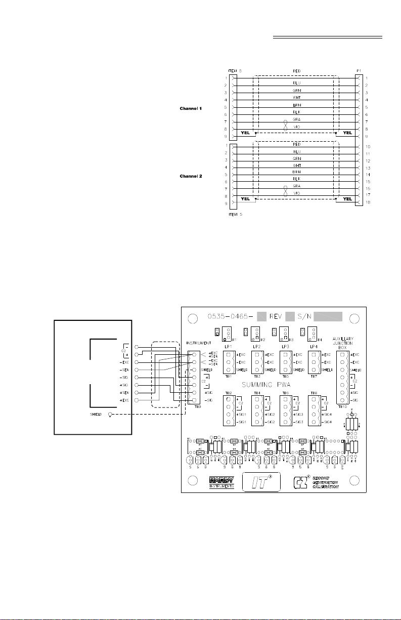
RTA CABLE ASSEMBLY - HI 17562WS DUAL CHANNEL - - - - -3-8
RTA CABLE SCHEMATIC - HI 1756-2WS DUAL CHANNEL- - - - -3-9
HARDY HI 215IT JUNCTION BOX WIRING DIAGRAM - - - - - - -3-9
CHAPTER 4 - SETUP - - - - - - - - - - - - - - - - - - - - - - -4-1
MODULE LEDS SINGLE CHANNEL - - - - - - - - - - - - - - - -4-1
MODULE LEDS DUAL CHANNEL‘ - - - - - - - - - - - - - - - - -4-1
COMMUNICATION CONFIGURATION DIALOG BOX- - - - - - - -4-3
DISCRETE DATA - - - - - - - - - - - - - - - - - - - - - - - - -4-7
PARAMETERS DIALOG BOX - - - - - - - - - - - - - - - - - - -4-10
PARAMETERS DIALOG BOX (CONT’D) - - - - - - - - - - - - - -4-10
MESSAGE CONFIGURATION EXAMPLE- - - - - - - - - - - - - -4-11
CHAPTER 5 - CALIBRATION - - - - - - - - - - - - - - - - - - -5-1
PROPERLY INSTALLED LOAD CELL W/NO BINDING - - - - - - -5-2
MILLIVOLTS/WEIGHT SCALE - - - - - - - - - - - - - - - - - - -5-3
“THE BUTTON” C2 CALIBRATION - HI 1756-WS - - - - - - - - - -5-5
“THE BUTTON” C2 CALIBRATION - HI 1756-2WS - - - - - - - - -5-5
CHAPTER 6 - OPERATING PROCEDURES - - - - - - - - - - - -6-1
COMMUNICATION CONFIGURATION DIALOG BOX- - - - - - - -6-1
DISCRETE DATA - - - - - - - - - - - - - - - - - - - - - - - - -6-2
CHAPTER 7 - TROUBLESHOOTING- - - - - - - - - - - - - - - -7-1
COMMAND RETURN PROCESS- - - - - - - - - - - - - - - - - -7-2
COMMAND DEFINITIONS AND ACTIONS - - - - - - - - - - - - -7-3
MECHANICAL INSPECTION - - - - - - - - - - - - - - - - - - - -7-5
LOAD SHARING AND LOAD SENSOR CHECKOUT - - - - - - - -7-6
I
Page 8

HI 1756-WS WEIGH SCALE MODULE
GUIDELINES FOR INSTABILITIES ON FORMERLY
OPERATING SYSTEMS - - - - - - - - - - - - - - - - - - - - - -7-7
GUIDELINES FOR INSTABILITIES ON FORMERLY
OPERATING SYSTEMS - ELECTRICAL - - - - - - - - - - - - - -7-8
MECHANICAL STABILITY AND CONFIGURATION SETTINGS - - -7-9
II
Page 9

CHAPTER 1 - OVERVIEW
Chapter 1 - Overview
A BRIEF
DESCRIPTION OF
CHAPTER 1
NOTE: Control/Logix® is a register ed trademar k of the Rock-
NOTE: WAVERSAVER®, C2®, INTEGRATED TECHNICIAN® are
This manual is designed for use by installers, operators, and service personnel. It provides specificat i ons
and procedures for linking, configuring, operating,
maintaining, and troubleshooting the Hardy Instru
ments HI 1756-WS and HI 175 6-2WS Control Logix®
I/O Weigh Scale Modules.
well Corporation.
Both modules come with WAVERSAVER®, C2® button-triggered calibration, INTEGRATED TECHNICIAN
®
) diagnostics, and ladder logic configurability.
(IT
registered trademarks of Hardy Instruments Inc.
Before using the product, be sure you understand all
cautions, warnings, and safety procedures stated or
referenced in this manual. And, to get the best service
from this product, follow the practices recommended
in this manual.
Hardy Instruments appreciates your business. We
welcome all corrections or suggestions for improve
ment of this manual. Should you not understand any
information in this manual or experience any prob
lems with the product, please contact our Customer
Support Department at:
-
-
-
Phone: (858) 278-2900
FAX: (858) 278-6700
e-mail: support@hardyinst.co m
Web: hardyinst.com
About This Manual Chapter 1 - Introduces the instruments and provides
an overview of the their capabilities
Chapter 2 - Provides a list of specifications
Chapter 3 - Contains instructions needed to install
the HI 1756-WS and HI 1756-2WS (both standard
and optional equipment) and the Remote Termination
Assembly (-RTA)
1-1
Page 10

HI 1756-WS WEIGH SCALE MODULE
Chapter 4 - Provides hardware configuration instructions, including dip switch and jumper settings.
Chapter 5 - Provides firmware/software setup procedures needed to operate and calibrate the instrument.
Chapter 6 - Provides calibration instructions.
Chapter 7 - Provides operating procedures.
Chapter 8 - Provides troubleshooting procedures.
Description Both the HI 1756-WS and HI 1756-2 WS Weigh Scale
Modules are self-contained, microprocessor-based
ControlLogix I/O modules with control inputs and
outputs that plug into the backplane of an Allen-Brad
ley ControLogix® programmable controller and/or
Remote Rack. The remote rack module connects to
the local chassis via a ControlNet link.
NOTE: The Allen-Bradley Control/Logix®manuals contain
useful information about their products that is not
provided in this manual. This manual assumes that
users have a basic understanding of process control
and can interpret ladder logic instructions as needed
to generate the electronic signals that control their
application(s).
-
1-2
The HI 1756-WS Weigh Scale Module Series A is
configured for single-channel operati on whil e the HI
1756-2WS Weigh Scale Module Series A is config
ured for dual-channel operation. Both modules can be
used for a wide variety of process weighing applica
tions such as batching, blending, filling/dispensing,
check weighing, force measurement, level by weight
and weight rate monitoring.
The analog-to-digital converter in the weigh module
controller updates fifty times per second and is capa
ble of 8,388,608 counts of display resolution. This is
enough to provide accurate weight measurement and
control and to tolerate large “dead” loads or over siz
ing of load cells/sensors. To calibrate the module you
can simply push “The Button” to effect a C2 elec
tronic calibration. C2, Hard (Traditional calibration
with weights) is also available for those not using
Hardy Instruments C2 certified load sensors.
-
-
-
-
-
Page 11

Chapter 1 - Overview
WAVERSAVER
®
During the measurement of small weight changes, the
affects of mechanical vibration and noise from the
operating environment can introduce substantial inter
ference. WAVERSAVER factors out vibration, noise,
and other interference-related signals from the load
cell so the rate controller can better decipher the
actual weight data.
WAVERSAVER® can be configured to ignore noise
with frequencies as low as 0.25 Hz. One of fi ve higher
additional cut off frequencies may be selected to pro
vide a faster instrument response time. The default
factory configuration is 1.00 Hz vibration frequency
immunity.
C2® Calibration Traditional calibration uses certified test weights.
C2® Electronic Calibration allows a scale to be cali
brated without the need for test weights. It can be ini-
tiated by pressing “THE BUTTON®” located in the
front of the module, or via ladder logic.
A C2 weighing system consists of up to eight C2 load
sensors, a junction box, interconnect cable, and an
instrument with C2 capabilities (e.g., the HI 1756).
Each Hardy Instruments C2-certified load sensor out
puts digital information used for the calibration. The
modules reads the sensor out puts and d etects t he num
ber of active sensors. It then calibrates the sca le based
on the load sensor’s output plus a user-supplied refer
ence point value (from 0 to any known weight on the
scale).
-
-
-
-
-
-
®
IT
INTEGRATED TECHNICIAN™ is a system diagnostics
utility which, in conjunction with an HI 215IT series
IT junction box, continuously monitors the excitation
circuit (with up to 4 load sensors) for possible mal
functions. IT reads individual load sensor voltages
and weights and isolates individual system compo
nents for quick and easy troubleshoot ing.
Excitation Monitor Continuously monitors a system’s excitation current
to check for open or shorted load sensors or damaged
or broken excitation wire(s), including the wires
-
-
1-3
Page 12

HI 1756-WS WEIGH SCALE MODULE
between the module, Remote Terminal Assembly
(RTA) and the IT
rent deviates more than a ± 10% tolerance, an “Excitation Error” bit (Module Status Word bit 9) is set to
1.
®
Junction box. If the measured cur-
Digital Volt Meter
(DVM) - Optional
Requires the HI 215IT Series Ju nction Box to monitor
both mV and mV/V readings for the system and per
individual load sensor. Once a problem is detected by
the operator the DVM readings help the operator to
isolate the faulty component. Further, the DVM read
ings can be used to level a system and to make corner
adjustments to platform scales. Accuracy is +/- 2% or
better of full scale.
NOTE: If you do not have the HI 215IT Junction Box con-
nected to the module, the mV/V reading as displayed
is the total for all the load cells on the system.
Return to Zero
Test - Optional
Requires the HI 215IT Series Ju nction Box to monit or
individual load sensors. This test compares the origi
nal voltage reading (saved at calibration) against the
current voltage reading of an empty vessel. The test
checks for damaged load sensors due to electrical zero
shift or abnormal mechanical forces that cause bind
ing on one or all of the load sensors in the system.
Weighing System
Tests - Optional
Requires the HI 215IT Series Junction Box for full
utilization. This test is used to diagnose drifting or
unstable weight reading problems. The Weighing Sys
tem Test does the following:
-
-
-
-
1-4
1. Disconnects the controller and engages an internal reference signal to see if the problem is within
the instrument.
2. Disconnects the load sensors and engages an
internal (in the junction box) reference signal to
see if the cable between the instrument and the
Junction Box is causing the problem.
3. Reads the weight of each load sensor to s ee if the
load sensor might be causing the problem.
Page 13

Chapter 1 - Overview
The ability to read the weight seen by each individual
load sensor allows use of this test to make cornering,
leveling and load sharing adjustments to the weighing
system.
AUTO ZERO TRACKING
NOTE: The amount of weight zeroed off is cumulative. The
Auto Zero Tracking automatically adjusts for zero
weight. This capability allows the module to ignore
material build-up in the weighing system within a preset auto zero tolerance. For auto zeroing to work cor
rectly, any “live weight” plus any weight previously
zeroed on the scale must be below the set Auto Zero
Tolerance value and the scale must not be in motion.
This is not used on all applications and should be
reviewed before use.
Autozero command will fail if the current gross weight
plus any previously zeroed amount exceeds the zero
tolerance value.
-
1-5
Page 14

HI 1756-WS WEIGH SCALE MODULE
1-6
Page 15

CHAPTER 2 - SPECIFICATIONS
Chapter 2 - Specifications
A Brief Description of Chapter 2
Specifications for a Standard HI 1756-WS (-2WS) Weigh Scale Module
Channels 2 Channels
Conversion Rate 50 updates per second Averages 1-255 User Selectable in single increments Resolution Internal: 1:8,388,608 Input Up to eight (8) 350 ohm Full Wheatstone Bridge,
Chapter 2 lists the specifications for the HI 1756-WS
and HI 1756-2WS Weigh Scale Modules. Specifica
tions are listed for the standard instrument and for
optional equipment. The specifications listed are
designed to assist in the installation, operation and
troubleshooting of the instrument. All service person
nel should be familiar with this section before
attempting an installation or repair of this instrument.
• Single Channel HI 1756-WS
• Dual Channel HI 1756-2WS
Strain Gauge Load Sensors/Cells (5 volt excitation)
on one vessel.
-
-
Non-Linearity 0.0015% of Full Scale
WAVERSAVER
Excitation Monitor Current less than +/- 10% expected Common-Mode
Rejection
®
User Selectable
• 7.50 Hz
• 3.50 Hz
• 1.00 Hz (Default)
• 0.50 Hz
• 0.25 Hz
110dB at or below 60 Hz
2-1
Page 16

HI 1756-WS WEIGH SCALE MODULE
Common-Mode Voltage Range
Backplane Input Voltage
Backplane Current Load
Backplane Power Load
C2 Calibration Input
Cable lengths 1000 feet maximum of C2 authorized cable
Load Cell Excitation
C2 Calibration Output
Environmental Requirements
2.5VDC maximum (with respect to earth ground)
5 VDC and 24 VDC
<1 Amp at 5 VDC
0.0125 Amps at 24 VDC (with 4-35 0 Ohm Load Cel ls
< 5W at 5 VDC
< .3W at 24 VDC with 4-350 Ohm Load Cells
Isolation from digital section 1000 VDC minimum.
250 feet maximum of C2 authorized cable (Maximum
of 4 load sensors) with IT Junction box.
5 VDC +/- 1.15 W maximum.
Isolation from digital section 1000 VDC minimum
Isolation from digital section 1000 VDC minimum
Temperature Coefficient
Operating Temperature Range
Storage Temperature Range
Humidity Range 0-90% (non-condensing) Approvals CE Approval
Digital Voltmeter Accuracy +/- 2% of full scale
2-2
Less than 0.005% of full scale per degree C for CalLO and Cal-HI reference points
0o C to 60o C (32o F to 140o F)
-40o C to 85o C (-40o F to 185o F)
UL, CUL (pending)
Resolution
Page 17

Optional Equipment
Chapter 2 - Specifications
• mV/V 4 digits to the right of the decimal
1756 RTA (Remote Termination Assembly
RTA Cable Assemblies
HI 215IT Series Junction Box
Default Parameters
Hardy Part # -RTA (HI-1756-XX-RTA if ordered separately) Remote Termination supports two (2) separate HI 1756-WS weigh scale modules or one (1) HI
1756-2WS weigh scale module. Unit includes DIN
rail mounting for 35mm x 15mm DIN rail.
Hardy Part # -C6 (HI 1756-XX-C6)
• Cable Length: 6 ft. (1.525 meters) from
the single channel module to the RTA.
Hardy Part # -C6 (HI 1756-XX-DC6)
• Cable Length: 6 ft. (1.525 meters) from
the dual channel module to the RTA.
NEMA rated waterproof enclosure which sums from
one to four load sensors load sensors.
• -PS1 NEMA 4 Painted Steel
• -SS1 NEMA 4X Stainless Steel
• -FG1 NEMA 4X Fiberglass
Parameter Default Setting
ChanActive 1 On
calyear*
calmonth*
calday*
calid[2]*
Calib Type
tareweight 0.0 lbs
Table 2-1: Default Parameters
2-3
Page 18

HI 1756-WS WEIGH SCALE MODULE
Parameter Default Setting
Metric lbs 0
WAVERSAV ER
SpanWeight 10,000.00
CalLowWeight lbs 0
Num Averages 10
ZeroTrackEnable False 0
ROCTimeBase 10
ZeroTolerance 10
AutoZeroTolerance 10.0 lbs
MotionTolerance 5.0 lbs
®
1 Hz 3
Table 2-1: Default Parameters
NOTE: * The HI 1756 modules do not have a rea l time clock,
so the year; month; day and calid must be set by the
operator.
2-4
Page 19

CHAPTER 3 - INSTALLATION
Chapter 3 - Installation
A Brief Description of Chapter 3
Unpacking Step 1. Before signing the packing slip, inspect
Chapter 3 provides the recommended procedures for
unpacking, cabling, interconnecting, configuring and
installing the Weigh Scale Module. Users and service
personnel should be familiar with this information
before installing or operating the Weigh Scale mod
ule. If you experience any problems installing this
equipment, contact Hardy In str uments In c., Custo mer
Support for assistance.
the packing for damage of any kind, and
report any damage to the carrier company
immediately.
Step 2. Check to see that everything in the pack-
age matches the bill of ladi ng. You should
normally have:
• HI 1756-WS or HI 1756-2WS Weigh
Scale Module
• Operation and Installation Manual
Step 3. Write down the Model and Serial number
of the module. You may need this infor ma
tion when contacting The Customer Support Department for part s or service.
-
-
Installing the
HI 1756-WS (-2WS)
into an Allen-Bradley
ControlLogix
Processor or AllenBradley Remote Rack
WARNING ELECTROSTATIC DISCHARGE MAY DAM-
AGE SEMICONDUCTOR COMPONENTS IN
THE MODULE. DO NOT TOUCH THE CON
NECTOR PINS.
Observe the following handling precautions:
• Wear an approved wrist-strap ground-
ing device when handling t he module.
-
3-1
Page 20
HI 1756-WS WEIGH SCALE MODULE
• T ouch a grounded ob ject or surface to
rid yourself of any electrostatic dis
charged prior to handling the module.
• Handle the module from the bezel in
front away from the connector. Never
touch the co nnector pins.
• Do not install the module right next to
an AC or high voltage DC module.
• Route all the load voltage cables
away from high voltage cables.
-
Installing the
HI 1756WS (2WS)
into the
ControlL
ogix
Chassis
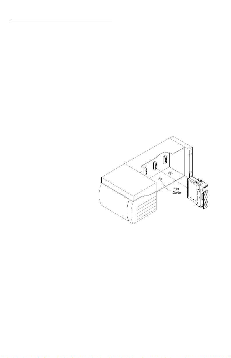
Step 1. Make sure that the module is oriented cor-
rectly for installation. (See Fig. 3-1)
FIG. 3-1 POSITIONING THE MODULE FOR
INSTALLATION
Step 2. Gently slide the module into the Chassis.
Step 3. Slide the digital board between the PCB
Guides on the top plate and bottom plate
of the chassis to line up the module con
nector with the backplane connector.
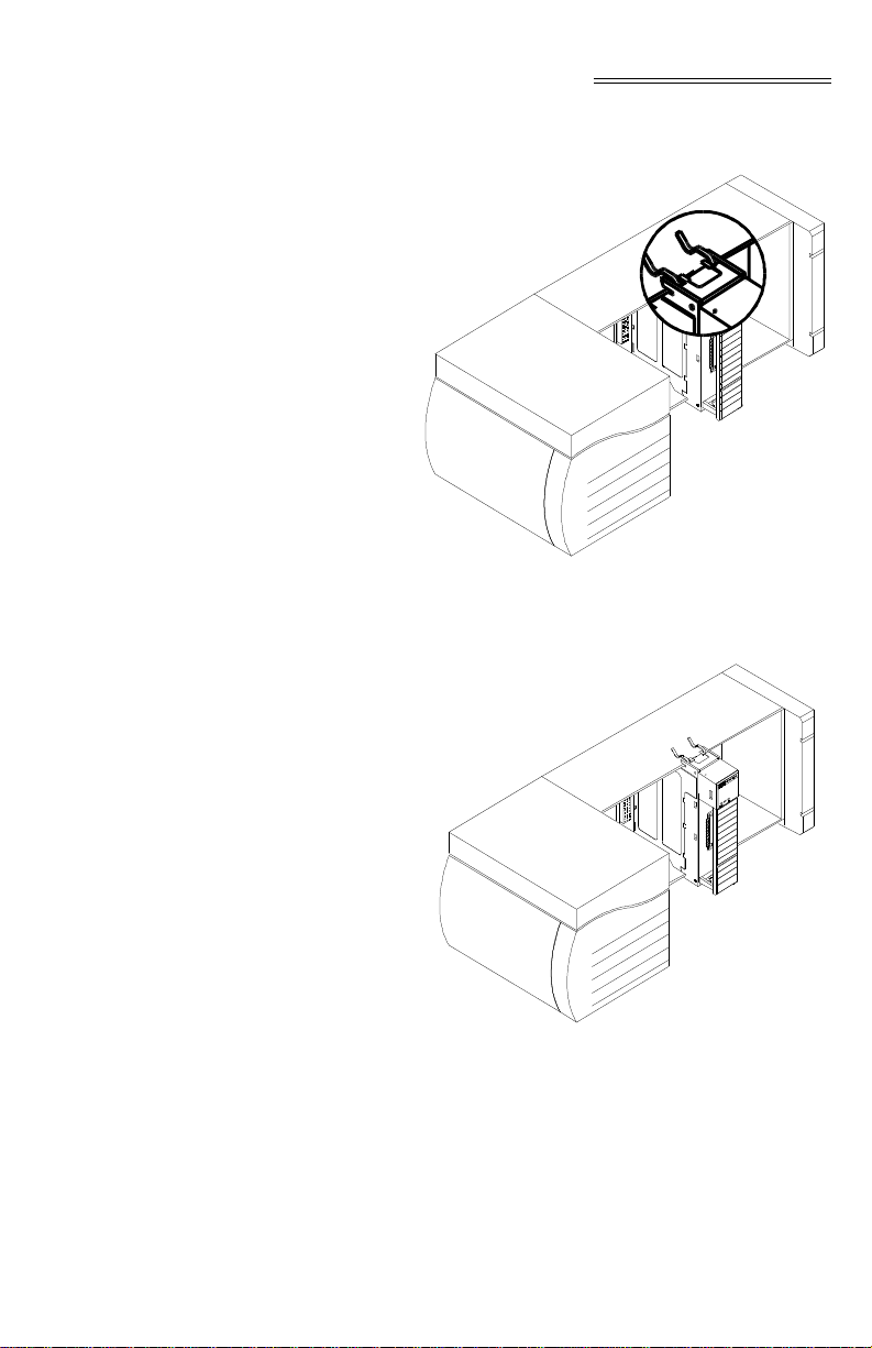
Step 4. When the module connector is touching
the backplane connector, firmly but care
fully push toward the chassis until the pins
are plugged in and the Processor Releases
(both top and bottom) are snapped into
place. (See Fig. 3-2 & 3-3)
-
-
3-2
Page 21
Chapter 3 - Installation
Step 5. The installation is complete.
FIG. 3-2 MODUL E RELEASE(S )
Removing the Module from the Chassis
FIG. 3-3 MO DULE INSTALLED IN CHASSIS
Step 1. Press down on the top and bottom proces-
sor releases simultaneously and pull the
module out of the chassis. (See Fig. 3-3)
Step 2. Store the module in a safe, secure location
in an anti-static bag or its original package.
3-3
Page 22

HI 1756-WS WEIGH SCALE MODULE
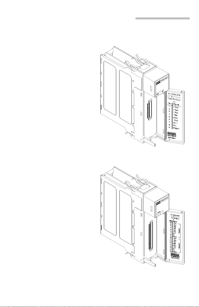
Installing the Module I/ O Connector
About the Module I/O Connector
The I/O Connector at the front of the module connects
the module to the Remote Terminal Assembly (RTA), a load sensor, or the HI 215IT Series Junction
Box, depending on how many load sensors are
installed in the weighing system. See below for the
pin-out diagram, which is also located on the inside of
the module door. (See Fig. 3-4 & 3-5)
Single Channel Dual Channel
Pin 1 Exc+
Pin 2 Sense+
Pin 3 Sig+
Pin 4 SigPin 5 SensePin 6 ExcPin 7 C2+
Pin 8 C2Pin 9 Shield
Pin 1 Exc+
Pin 2 Sense+
Pin 3 Sig+
Pin 4 SigPin 5 SensePin 6 ExcPin 7 C2+
Pin 8 C2Pin 9 Shield
Pin 10 Exc+
Pin 11 Sense+
Pin 12 Sig+
Pin 13 SigPin 14 SensePin 15 ExcPin 16 C2+
Pin 17 C2Pin 18 Shield
Step 1. Open the Module door to gain access to
the I/O connector. (See Fig. 3-4 & 3-5)
Step 2. Install the cable and connector so it allows
the module door to be shut.
Step 3. With the plug oriented correctly (See the
pin-out diagram above), plug the I/O male
connector into the I/O connector at the
front of the module.
Step 4. Verify that the connector is completely
plugged in before opera ting the module.
NOTE: Most problems are due to loose connections. Be sure
to check the I/O connection first if you have a problem
3-4
Page 23
Chapter 3 - Installation
receiving information from the load cells or if the
relays do not operate correctly.
FIG. 3-4 HI 1756-WS WITH DOOR OPEN
FIG. 3-5 HI 1756-2WS WITH DOOR OPEN
3-5
Page 24
HI 1756-WS WEIGH SCALE MODULE
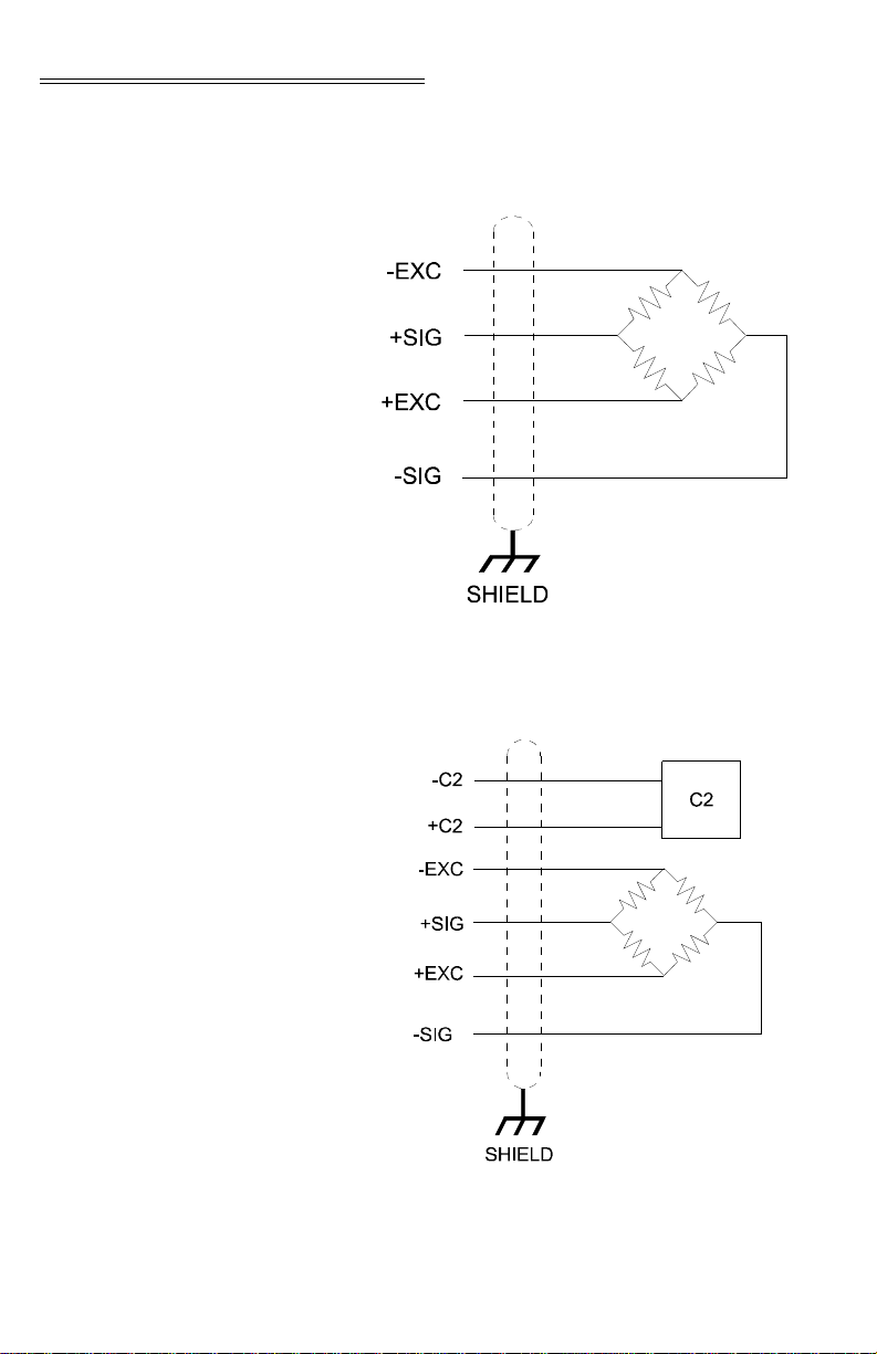
Load Cell Wiring Diagrams
Industry Standard Load Cells
FIG. 3-6 INDUSTRY STANDARD LOAD CELLS
WIRING DIAGRAM
Hardy Load Sensor with C2
3-6
FIG. 3-7 HARDY LOAD SENSOR/C2 WIRING
DIAGRAM
Page 25
Chapter 3 - Installation
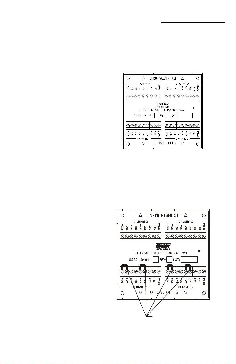
HI 1756 Remote Terminal Assembly (HI 1756-XX-RT)
NOTE: When using load cells that do not have sense lines you
The RTA provides connection points between the HI
module’s cable assembly and the wires from the junc
tion box(es) or load sensor(s). It comes with a standard 35 mm Din Rail Mounting and requires at least a
5” inch DIN rail for mounting.
FIG. 3-8 REMOTE TERMINAL ASSEMBLY
will need to jumper the Sense (-) to the Excitation (-)
and the Sense (+) to the Excitation (+) for one or both
channels. (See Fig. 3-9)
-
Jumpers
FIG. 3-9 RTA WITH JUMPERS FOR LOAD
CELLS WITHOUT SENSE LINES
3-7
Page 26
HI 1756-WS WEIGH SCALE MODULE
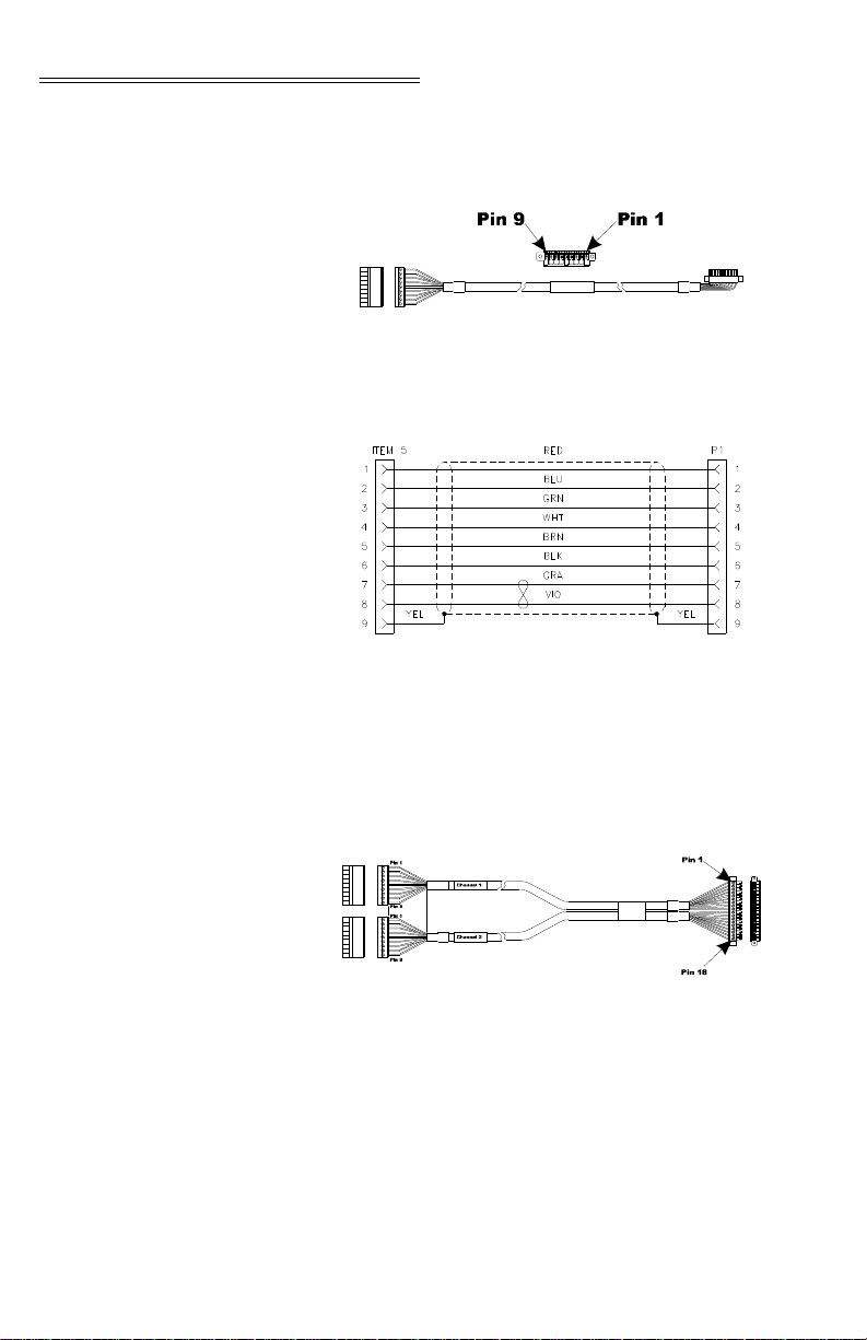
RTA Cable Assembly
• Six (6) foot cable that connects to the HI 1756WS module.
FIG. 3-10 RT A CABLE ASSEMBLY - HI 1756WS
SINGLE CHANNEL
FIG. 3-11 RTA CA BLE SCHEMATIC - HI
1756WS SINGLE CHANNEL
3-8
• Six (6) foot cable that connects to the HI 17562WS module
FIG. 3-12 RTA CAB LE ASSEMBLY - HI
17562WS DUAL CHANNEL
Page 27
Hardy HI 215IT
Load
Cell
Connector
J1
Junction Box
Chapter 3 - Installation
FIG. 3-13 RTA CABLE SCHEMATIC - HI 1756-
2WS DUAL CHANNEL
FIG. 3-14 HARDY HI 215IT JUNCTION BOX WIRING DIAGRAM
NOTE: When connecting the Hardy HI 215IT Junction Box
you must remove the two factory installed jumpers
1&2 and 5&6 on the module install sense lines.
3-9
Page 28

HI 1756-WS WEIGH SCALE MODULE
3-10
Page 29

CHAPTER 4 - SETUP
Chapter 4 - Setup
A Brief Description of Chapter 4
Power Check Step 1. To make or change settings, there must be
Chapter 4 covers the firmware and software settings
used to prepare the module controller for calibration
and operation. The Setup procedures require AllenBradley’s RS Logix 5000, Allen-Bradley RSLinx™
or RSLinx™ Lite.
power to both the PLC and the module.
Veri fy th at the LED’s are lit for normal
operation. (See Figs. 4-1 and 4-2)
FIG. 4-1 MODULE LEDS SINGLE CHANNEL
FIG. 4-2 MODULE LEDS DUAL CHAN NEL ‘
4-1
Page 30

HI 1756-WS WEIGH SCALE MODULE
LEDS
Scale Data LEDs
OK Module Status LED
Reset Module Message
Flashing Green Error No Calibration
Steady Green Running (Normal)
Steady Red Error Read Failure or Error eeprom
write. Contact HI Customer Sup-
port
Flashing Red Read Convert Error.
LED is Off Channel is Inactive
Brief Steady During power up the LED lights
Red for about one second.
Flashing Green In Program mode. (Normal)
Steady Green In Run Mode. (Normal)
Steady Red Config. Fault The eeprom
(Backplane checksum failed - bad serial eeprom
A vailable) data or blank serial eeprom. Contact
HI Customer Support.
Steady Red Internal Hardware watchdog timer
fault (e.g. bad Hardware or Firm-
ware). ASIC is non-operational.
Flashing Red Communication Error.
Modules with communication errors (indicated by a
flashing red Module Status LED) can be reset by a
reset message.
Setting Up Communications Between the PLC and the HI 1756- WS (-2W S) Weigh Scale Module
4-2
• Message Type: CIP Generic
• Service Code 5 (Hex)
• Class Name: 1
• Instance Name: 1
Follow these steps to set up communication between
the ControlLogix PLC and the Weigh Scale Module.
The steps require that you have a new or open RS
®
Logix
5000 project. For instructions, see your RS
LOGIX 5000 manual.
Step 1. Look for a list of folders on the left side of
the screen. Scroll to and select the I/O
Config folder, which will open a menu.
Page 31

Chapter 4 - Setup
Step 2. Select New Module to display a list of
modules.
Step 3. Scroll to and select the Generic 1756 mod-
ule to open the Module Properties form.
Step 4. Enter the following connection parameters
in the appropriate fields:
• Name of Module
• Description of Module (Optional)
•Slot ID
• Input Assembly Instance:101 Size = 11
• Output Assembly Instance: 146 Size = 1
• Configuration Asse mbly Instance:241
NOTE: Size = 0 configuration table not used)
or (with version 2.3 software):
Size = 64 (8-bit) for a 1-channel unit
Size = 128 (8-bit) for a 2-channel unit
Step 5. Select DATA REAL from the Comm For-
mat pull-down list.
FIG. 4-3 COMMUNICATION
CONFIGURATION DIALOG BOX
Step 6. Open the Connection Tab.
Step 7. Set the RPI to 20 milliseconds or greater.
Do not set this parameter lower than 20
milliseconds.
Step 8. Click on Finish.
4-3
Page 32

HI 1756-WS WEIGH SCALE MODULE
Configuration Parameters for the HI 1765-WS Module
With version 2.3 software, the HI 1765-WS module
can recieve 32 words of the configuration data from a
PLC upon power-up. These data are used only if the
value for Config_rev_num is set to 1 and the parame
ters are sent in the correct format and range.
NOTE: DINT Parameters can be interpreted as floating point
based on the value of a bit within the DecimalPoints
parameter of the channel.
Parameter
Offset (In
Words)
Single Channel
Config_rev_num0 *
ChanEnabled0
DecimalPoints0 **
Metric0
NumAverages0
Waversaver0
0
1
2
3
4
5
-
4-4
SpanWeight0
CalLowWeight0
ZeroTrackEnables0
AutoZeroTolerance0
MotionTolerance0
TareWeight0
EnableButton0
RocTimeBased0
ZeroTolerance0
Spare1_0
6
7
8
9
10
11
12
13
14
15
Page 33

Chapter 4 - Setup
Parameter
Dual Channel
Config_rev_num1 *
ChanEnabled1
DecimalPoints1 **
Metric1
NumAverages1
Waversaver1
SpanWeight1
CalLowWeight1
ZeroTrackEnables1
AutoZeroTolerance1
MotionTolerance0
TareWeight0
Offset (In
Words)
16
17
18
19
20
21
22
23
24
25
26
27
EnableButton0
RocTimeBased0
ZeroTolerance0
Spare1_0
28
29
30
31
* Must be set to 1 for the other values to apply
** Converts integers to floating-point
When the parameters are displayed, they do not
appear in the form above. They may look more like
this:
Local:1:C.Data[0]
Local:1:C.Data[1]
...and so on
4-5
Page 34

HI 1756-WS WEIGH SCALE MODULE
Input Data This is discrete input data which is a module-defined
data type, LOCAL:X:I (where X is the slot number).
NOTE: The TimeStamp is a 64-bit integer giving the system
time in microseconds.
STATUSWORD The module returns a binary statusword where each
bit indicates a state or condition within the module. To
interpret these states, note which bits are ON and use
the chart below to match each bit location to the state
it represents.
For Example: If the satausword is 69 with a binary
value of 0000 0000 0100 0101, bits 0, 2 an 6 are on.
Bit 0 indicates an A/D conversion error, bit 2 indi
cates the unit is calibrated in lbs. and bit 6 indicates
the scale is in motion.
-
NOTE: The screen in Fig. 4-4 shows input data in floating-
point format. To read the data bits, the Word0 status
word must be copied to a double integer tag. The first,
least significant 16 bits apply to channel 0. In a twochannel module, the 16 most significant bits apply to
channel 1; otherwise the upper 16 bits are not used.
4-6
-
Page 35

Chapter 4 - Setup
FIG. 4-4 DISCRETE DATA
STATUSWORD bit positions refer to these variables :
Word Number Definition
ERRORADCONVERT 0x0001 Millivolt return from the load cell
ERRORADFAILURE 0x0002 A/D converter in the unit is no
STATUSENGLISH 0x0004 Unit calibrated in lbs. If the bit is
STATUSZTRACK 0x0008 Auto Zer o Trac k ing is turned on .
STATUSBUTTONENABLED
STATUSINMOTION 0x0040 Weight is changing on the scale.
ERRORNOCAL 0x0080 The unit is at factory defa ul t se t-
ERROREEPROMWRITE 0x0100 EEPROM Hardware Error
ERROREXCITEMON 0x0200 Excitati o n monitor error.
ERRORMAX144 0x0400 Hardwar e E rror i n Excitation
STATUSCMDRCVD 0x2000 Output Table Command Complete
0x0010 Enabled/Disable d ca librate button.
system is out of range for the unit.
longer responding.
off, calibrated in kgs.
tings.
Monitor
4-7
Page 36

HI 1756-WS WEIGH SCALE MODULE
Word Number Definition
STATUSCMDERROR 0x4000 Output Table Command Failed
STATUSCHANENABLED 0x8000 Set if chann el is enabled
Parameters for the HI 1756-WS (-2WS) Module
NOTE: The Glossary at the end of this manual provides addi-
tional information about the parameters and other
common wei gh process definitions.
All parameters in Table 4-1 are either type DINT (4byte integer) or REAL (4-byte floating point).
# Type Parameter Description
1 DINT ChanActive Flag, determines if a channel is alive.
2 DINT calyear Year of last Cal ibration*
3 DINT calmonth Month of last Calibration*
4 DINT calday Day of last Calibration*
5 DINT[2]calid[2] ID of calibrator using init ia ls. e.g. JB*
6 DINT CalibType Read Only
7 REAL tareweight Tare weight in lbs or kgs as determined
8 DINT Metric Report weight in lbs or kgs.
Legal values are: 0 (Channe l Off) or 1
(Channel On)
Button = 3
C2 = 1
Hard Cal = 0
Never Calibrated = FFFF
by Metric.
Legal Values
lbs = 0
kgs = 1
TABLE 4-1: PARAMETERS
4-8
Page 37

# Type Parameter Description
Chapter 4 - Setup
9 DINT Waversaver Legal Values are 0-4
10 REAL SpanWeight Calibration weight, high, in lbs or kgs
11 REAL CalLowWeight Calibration weight, low, in lbs or kgs
12 DINT NumAverages Legal Values: 1-255
13 DINT ZeroTrackEnable Enable for Zero Tracking
14 DINT ROCTimeBase Legal Values: 1-1800 seconds
15 REAL ZeroTolerance In lbs or kgs.
16 REAL AutoZeroTolerance In lbs or kgs
17 REAL MotionTolerance In lbs or kgs
0 = 7.5 Hz
1 = 3.5 Hz
2 = 1 Hz
3 = .5 Hz
4 = 0.25 Hz
Legal Values:
0 = Not Enabled
1 = Enabled
TABLE 4-1: PARAMETERS
NOTE: *Since the 1756 module has no real-time clock, the
operator must set the ye ar, month, day, and calid.
4-9
Page 38

HI 1756-WS WEIGH SCALE MODULE
FIG. 4-5 PARAMETERS DIALOG B OX
4-10
FIG. 4-6 PARAMETERS DIALOG BOX (CONT’D)
Page 39

Chapter 4 - Setup
Commands Commands are configured in the RSLOGIX 5000 as
follows:
• Message Type: CIP Generic
• Service Code 4c (Hex)
• Class Name: 4
• Instance Name: 254
• Object Attribute: None, leave this field b lank
• Message source: a tag defining the data sent
to the HI 1756-WS (-2WS).
• Number of elements: defined by the command used.
• Message destination: a tag where the reply
data will be written.
FIG. 4-7 MESSAGE CONFIGURAT ION
EXAMPLE
All commands begin with the following fields:
• Command (DINT): The command number
• Channel (DINT): The channel number (mus t
be 0)
NOTE: Some commands require additional fields, as speci-
fied in the command.
4-11
Page 40

HI 1756-WS WEIGH SCALE MODULE
Reply data contains 3 fields
• Command (DINT): The command number
• Channel (DINT): The channel number
• Status (DINT): Status information
NOTE: Some commands will produce longer replies.
Zero Command (ZEROCMD)
NOTE: The amount of weight zeroed off is cumulative. The
Tare Command (TARECMD)
The Zero Command requests that the current gross
weight be set to zero.
Command Number: 1 (Hexadecimal)
Channel Number: 0 or 1
Number of Elements: 8
Error Return Values:
• OUTOFTOLERANCE - the current weight
value is beyond the limits set by the zero toler
ance parameter.
Autozero command will fail if the current gross weight
plus any previously zeroed amount exceeds the zero
tolerance value.
• “STATUSWORD” - the command failed
because either the weight was not stable (in
motion) or there was some kind of A/D error.
The T are Command requ ests the current n et weight be
set to zero.
Command Number: 2 (Hexadecimal)
Channel Number: 0 or 1
Number of Elements: 8
-
4-12
Error Return Values:
• “STATUSWORD” - the command failed
because either the weight was not stable (in
motion) or there was some kind of A/D error.
Page 41

Chapter 4 - Setup
Write Non-Volatile
Command
(WRITENONVOL
ATILE)
Reload NonVolatile
(RELOADNONVOL
ATILE)
Enable Calibration Button Command (ENABLEBUTTON CMD)
The Write Non-Volatile Command causes all parameters (including calibration constants) to be saved to
the non-volatile memory.
Command Number: 4 (Hexadecimal)
Channel Number: 0 or 1
Number of Elements: 8
Error Return Values: None
The Reload Non-Volatile Command causes the weigh
module to re-read the values stored in its non-volatile
memory . Any parameters changed since the last write
non-volatile command are overwritten. this command
can be used to abort a calibration or parameter entry
session.
Command Number: 0x10 (Hexadecimal)
Channel Number: 0 or 1
Number of Elements: 8
Error Return Values: None
The Enable Calibration Button Command activates
the calibration button.
Command Number: 20 (Hexadecimal)
Channel Number: 0 or 1
Number of Elements: 8
Disable Calibration Button Command (DISABLEBUTTON CMD)
Set Default Parameters (SETDEFAULTPAR AMS)
Error Return Values: None
The Disable Calibration Button Command deactivates
the calibration button.
Command Number: 40 (Hexadecimal)
Channel Number: 0 or 1
Number of Elements: 8
Error Return Values: None
Load the default settings into RAM, and non-volatile
RAM.
Command Number: 0x94 (Hexadecimal)
4-13
Page 42

HI 1756-WS WEIGH SCALE MODULE
Channel Number: 0 or 1
Number of Elements: 8
Error Return Values: None
Cal Low Command (CALLOWCMD)
Cal High Command (CALHIGHCMD)
The Cal Low Command sets the “calLowCount”
parameter to the current A/D average counts when
doing a hard calibration. An Integrated Technician
function gets called during low calibration.
Command Number: 0x64 (Hexadecimal)
Channel Number: 0 or 1
Number of Elements: 8
Error Return Values:
• STATUS WORD - there was a conversion error,
weight in motion or an A/D error or all three.
• HARDCALFAILCOUNTS - less than 100
counts between the zero and the span weights.
The Cal High Command - Sets the Span Weight
parameter to the current A/D average counts when
doing Hard CAL.
Command Number: 0x65 (Hexadecimal)
Channel Number: 0 or 1
Number of Elements: 8
Error Return Values:
C2 Cal Command (C2CALCMD)
4-14
• STATUSWORD - there was a conversion error,
weight in motion or an A/D error or all three.
• HARDCALFAILCOUNTS - there are less than
100 counts between the zero and the span
weights.
The C2 Cal Command - Performs a C2 Calibration.
Uses CalLowWeight as the reference point.
Command Number: 0x66 (Hexadecimal)
Channel Number: 0 or 1
Number of Elements: 8
Page 43

Chapter 4 - Setup
Error Return Values:
• STATUSWORD - there was a conversion error,
weight in motion or an A/D error or all three.
• C2FAILNODEVS - detected no C2 load cells.
• C2FAILCAPEQ - detected two load cells with
different capacities.
Read Weight Cal
Command
(
READWEIGHTCAL)
Perform Integrated Technician Tests (WEIGHSYSTEST)
Weight data at calibration points are saved. The Read
Weight Cal Command reads in the values, letting you
compare raw counts at current input and counts at cal
ibration points to ensure the the scale is returning correct input from each calibration point before running
new calibration command.
Command Number: 0x63 (Hexadecimal)
Channel Number: 0 or 1
Number of Elements: 8
Return Values:
Command (DINT)
Channel (DINT)
Status (DINT)
Zero counts (DINT)
Cal zero counts (DINT)
Cal low counts (DINT)
Cal high counts (DINT)
CalibK (weight per count) (REAL)
ADC (as of the time the command is given) (DINT)
Performs the Integrated Technician tests.
Command Number: 0x6D (Hexadecimal)
Channel Number: 0 or 1
Number of Elements: 16
Status
nSensors: Number of Sensors.
-
4-15
Page 44

HI 1756-WS WEIGH SCALE MODULE
Structure (ITECHTEST)
Structure Item Description
DINT command* 0x66
DINT channel* 0 or 1
DINT status* N/A
DINT nSensors* Number of load sensors.
REAL BaseR Load cell impeda nc e measured during Calibrati on
REAL ReadR Impedance measured at test time
DINT TestR Test Result: Good = True, Bad = False
REAL Vsense Sense Voltage from the load cells
REAL loadcell current Load Cell Current
DINT RTZ_R_combined Test result, return to zero, al l lo ad cells
DINT RTZ_R_1** Test result, return to zero, load cell 1
DINT RTZ_R_2** Test result, return to zero, load cell 2
4-16
DINT RTZ_R_3** Test result, return to zero, load cell 3
DINT RTZ_R_4** Test result, return to zero, load cell 4
REAL DVM_combined Millivolts/Volt, all load cells
REAL DVM_1** Millivolts/Volt, load cel l 1
REAL DVM_2** Millivolts/Volt, load cel l 2
REAL DVM_3** Millivolts/Volt, load cel l 3
REAL DVM_4** Millivolts/Volt, load cel l 4
REAL IREF_weight Internal refe rence counts, converted into a weight
REAL JBOXREF_weight JBOX reference counts, c onverted into a weight
REAL grossweight Combined Gross Weight, all load cells
REAL weight_1** Gross We ig ht, lo ad cell 1
REAL weight_2** Gross We ig ht, lo ad cell 2
REAL weight_3** Gross We ig ht, lo ad cell 3
Page 45

Structure Item Description
REAL weight_4** Gross We ig ht , lo ad cell 4
NOTE: * Required Command Data
* * Available only with the HI 215IT Junction Box.
Chapter 4 - Setup
Search for C2 Load Sensors (C2SEARCH)
Read C2 Sensor Serial Number (READC2SERIALN UM)
Searches for C2 Load Sensors
Command Number: 0x6E (Hexadecimal)
Channel Number: 0 or 1
Number of Elements: 8
Return Values:
• COMMAND
• CHANNEL
•STATUS
• C2ROM - The number of C2 sensors detected.
• C2SWITCH - The number of JBOX switches
detected.
• CAPACITY - Combined sensitivity of C2 load
cells.
• SENSITIVITY - Combined sensitivity of C2 load
cells.
Reads the serial number of a specified C2 load sensor.
Must be preceded by the C2SEARCH command.
Command Number: 0x70 (Hexadecimal)
Required Command Data:
• COMMAND
• CHANNEL
• SENSOR # (0-7 Number of specific Load Cell
Requested)
• Number of Elements: 12
4-17
Page 46

HI 1756-WS WEIGH SCALE MODULE
Return Data:
• COMMAND
• CHANNEL
•STATUS
• 9 DINT SERIAL NUMBER
Error Return Values:
• OUTOFTOLERANCE - No C2 Sensor found.
Read Status of Module (GETSTATUS)
NOTE: See the Timed Out Command sectio n.
Write Parameters (WRITEPARAM)
Reads the condition of the module.
Command Number: 0x80 (Hexadecimal)
Channel Number: 0 or 1
Number of Elements: 8
Return Data:
• COMMAND
• CHANNEL
• STATUS - Returns status of the last timed out
command.
Writes all the parameters.
Command Number: 0x68 (Hexadecimal)
Channel Number: 0 or 1
Number of Elements: 84
Return Data:
• COMMAND
• CHANNEL
4-18
• STATUS - The status is 0 if the command succeeded. If there was a range error detected in one
of the parameters, a non-zero value is returned
indicating which parameter failed its range. (See
Table 4-1)
Page 47

Chapter 4 - Setup
Read Parameters (READPARAM)
Read Live Weight
(READLIVEWEIGHT)
Reads all the parameters.
Command Number: 0x69 (Hexadecimal)
Channel Number: 0 or 1
Number of Elements: 8
Return Data:
• COMMAND
• CHANNEL
•STATUS
• PARAMETERS (See Table 4-1)
Reads gross weight in units set by the Metric Parameter, either lbs or kgs.
Command Number: 0x6B (Hexadecimal)
Channel Number: 0 or 1
Number of Elements: 8
Return Data:
• COMMAND
Command Table
• CHANNEL
• STATUS = STATUSWORD
• Gross weight in units determined by the Metric
Parameters
•Net Weight
• Rate of Change
• ADC value (A REAL number between 1.0 and
2.0)
Command
ZERO* 1
Number
(Hex)
4-19
Page 48

HI 1756-WS WEIGH SCALE MODULE
Command
TARECMD* 2
WRITENONVOLATILE* 4
RELOADNONVOLATILE* 0x10
GETSTATUS 0x80
ENABLEBUTTONCMD** 0x20
DISABLEBUTTONCMD** 0x40
SETDEFAULTPARAMS 0x94
CALLOWCMD* 0x64
CALHIGHCMD* 0x65
C2CALCMD* 0x66
WRITEPARAM 0x68
READPARAM 0x69
WEIGHSYSTEST 0x6D
C2SEARCH 0x6E
READC2SERIALNUM 0x70
Number
(Hex)
READLIVEWEIGHT 0x6B
NOTE: * These commands can be sent through the output
table. (See Below)
** Newly added
Output Table
Output (Commandword)
16 bits 16 bits
Channel 1 Channel 0
4-20
Page 49

The least significant 16 bits are a command for Channel 0, the next 16 bits are a command for Channel 1.
Commands are “1 shot”, occurring upon a 0-1 transition.
Bit 0x2000 in the STATUSWORD will be set upon
completion of the output table comand. Bit 0x4000
will also be set if the command failed. Setting the
command word to zero will clear these status bits.
Error Code List SUCCESS 0
OUTOFTOLERANCE -3
NOSUCHCMD -5
C2FAILNODEVS -6
C2F AILCAPEQ -7 (failure, capacities not
HARCALFAILCOUNTS -8 (failure, not enough
Chapter 4 - Setup
equal)
ADC counts b e tw e e n
high, low)
Timed Out Commands
Return Codes See Chapter 7, Troubleshooting.
The ASIC on the HI 1756-WS module requires that a
command receive a reply within 65 milliseconds.
This is not enough time to complete some of the com
mands. The commands subject to time-out are:
•CALLOWCMD
•C2CALCMD
• WEIGHSYSTEST
•C2SEARCH
The reply to these commands is sent before the commands are actually performed.
To see if a calibration has succeeded, the command
“GETSTATUS” can be sent
The data returned by the WEIGHSYSTEST and
C2SEARCH commands is actually the data deter
mined by an earlier command. In practice, these commands need to be sent twice .
-
-
4-21
Page 50

HI 1756-WS WEIGH SCALE MODULE
Calibration Setup Procedures
Setting the Unit of Measure
Setting the Motion Tolerance Value
Setting the Zero Tolerance Value
NOTE: The amount of weight zeroed off is cumulative. The
Setting the Auto Zero Tolerance Value
The Unit of measure can be set to either kilograms or
pounds. Any weight value input to the module (e.g.
CALLOWWEIGHT, SPANWEIGHT) are in the cur
rently selected units. The unit of measure can be set at
any time, not just at calibration. Setting the unit of
measure before calibrating reminds the us er what unit
of measure is being displayed. It is important t o note
that the weigh scale module does not need to be cali
brated again after changing the unit of measure.
The motion tolerance is the tolerance value used to
determine if the scale is in motion.
Sets the range of weights so that the Zero Command
works as an offset of the calibrated Zero.
zero command will fail if the current gross weight
plus any previously zeroed amount exceeds the zero
tolerance.
When the Auto Zero Tolerance is entered and Auto
Zero Tracking is enabled, any weight within the
entered tolerance of zero and not in motion will cause
the display to automatically read zero.
-
-
NOTE: The amount of weight zeroed off is cumulative. The
auto zero command will fail if the current gross
weight plus any previously zeroed amount exceeds the
zero tolerance.
NOTE: There is a short time delay (at least 1 second) before
the Auto Zero Triggers.
Setting the Number of Readings Averages
4-22
The Number of Averages sets the number of weight
readings which will be used to compute the displayed
weight. The average is a sliding average so that a new
average reading is available for display at every read
ing.
-
Page 51

Chapter 4 - Setup
Setting the Span Weight Value
Setting the
WAVERSAVER
®
Value
The Span Weight is a reference point derived from an
actual measured weight. This should not be confused
with the Scale Capacity. If you have a 100 pound
weight and you place it on the scale, the Span Weight
would be 100 pounds.
There are 5 selectable levels. 0 provides the least
vibration immunity with the fastest response time. 4
provides the most vibration immunity with the slow
-
est response time. Default setting is 2.
Immunity Setting
7.5 Hz 0
3.5 Hz 1
1.0 Hz 2
0.5 Hz 3
0.25 Hz 4
4-23
Page 52

HI 1756-WS WEIGH SCALE MODULE
4-24
Page 53

CHAPTER 5 - CALIBRATION
Chapter 5 - Calibration
A Brief Description of Chapter 5
NOTE: Do not perform a calibration while the application is
Pre-Calibration Procedures
Chapter 5 provides the recommended calibration procedures for the HI 1756 (WS or 2WS) Weigh Scale
Module. For the module to work properly, it must be
calibrated prior to operation, and it should be re-cali
brated periodically or when not in use for extended
periods of time. Be sure to follow all the procedures
completely to insure that the weights read by the mod
ule are accurate. Users and service personnel should
be familiar with the procedures in this chapter before
installing or operating the Weigh Module.
in operation.
Step 1. Determine if the load cells have been
properly installed. See your load cell I&M
manual for proper installation instructions.
Step 2. An arrown on some sensors and cells indi-
cates the correct direction of the applied
load. If the arrow points in the wrong
direction, reposition the load cell.
Step 3. Check for Binding on the Load Cell or
other parts of the weighing system.
-
-
CAUTION: BINDING ON A SCALE/VESSEL OR LOAD
CELL CAN DENY THE LOAD CELL FREE
VERTICAL MOVEMENT AND PREVENT THE
INSTRUMENT FROM RETURNING TO THE
ORIGINAL ZERO REFERENCE POINT.
• Mount load cells so that 100% of the load (Vessel
w/Contents) passes vertically through a cell. (See
Fig. 5-1)
• Veri fy that nothing is binding the load cell. No,
hose, electrical cord, tube, or other object should
be draped across the scale/vessel or the load cell.
• Ensure that nothing contacts the scale/vessel
other than service wires and piping that have
been properly mounted with flexible connectors.
5-1
Page 54

HI 1756-WS WEIGH SCALE MODULE
FIG. 5-1 PROPERLY INSTALLED LOAD CELL W/NO BINDING
Electrical Check Procedures
Load Cell/Point Input/Output Measurements
5-2
Step 4. Typical Load Cell/Point Input/Output
Measurements (EXC & SIG Outputs)
a. The Weigh Module is designed to sup-
ply 5 VDC excitation to as many as
eight 350 Ohm load cells/points.
b. The expected output from each load
cell/point depends on the mV/V rating
of the load cell/point and the weight.
For example, a 2mV/V load cell/point
will respond with a ma ximum of 10
mVDC at full system weight capacity,
which includes the weight of the vessel
and the weight of the product as mea
sured by the load cell/point. If the load
cell/point weight capacity is rated at
1000 pounds, the load cell/point will be
10 mVDC at 1000 pounds, 7.5 mVDC
at 750 pounds, 5 mVDC at 5 00 pounds.
-
Page 55

Chapter 5 - Calibration
c. A zero reference poin t will vary from
system to system depending on the
“Dead Load” of the vessel. “Dead Load”
is the weight of the vessel and appurte
nances only, with no product loaded. In
our example we will assume the dead
load to be 500 pounds. (See Fig. 5-2)
-
FIG. 5-2 MILLIVOLTS/WEIGHT SCALE
Based on the example, the operating range for this
scale is 5-10 mVDC with a 500 pound weight range.
Understand that after zeroing the instrument, the 0
reading refers to the zero reference point and not
absolute 0 mVDC or absolute 0 weight.
NOTE: Load cell/point measurements are checked with a dig-
ital volt meter at the J2 connector on the front of the
module or by using I
NTEGRATED TECHNICIA N with the
HI 215IT Junction Box.
Load Check Step 1. Place a load (weight) on the scale or vessel
and check to see if the weight reading
changes on the ladder logic display in the
proper direction.
5-3
Page 56

HI 1756-WS WEIGH SCALE MODULE
Step 2. If the ladder logic display changed weight
C2 Calibration
• For example: If the ladder logic display reads 100 pound s and a 20 pound
weight is placed on the vessel or
scale, the ladder logic display should
read 120 or some value over 100.
• If the ladder logic display reads 100
pounds and a 20 pound load is placed
on the vessel or scale and the reading
is 80 pounds, the reading is going in
the wrong direction and indicates
some problem with the system.
• If the ladder logic display is reading
improperly or shows no change there
is something wrong with the setup.
in the proper direction, remove the weight
and proceed to calibrate the module.
About C2 Calibration
“THE BUTTON” C2 Calibration
5-4
C2 calibration requir es C2 l oad s ens ors . If y ou d o not
have C2 load sensors you must perform a traditional
calibration with test weights which we call a Hard
Calibration. The Weigh Module reads the perfor
mance characteristics of each individual load cell and
detects the quantity of load cell(s) in the system. C2
Calibration can be performed by pressing “The But
ton” located in the front of the module, or via Allen
Bradley RS LOGIX 5000.
Step 1. Be sure that the parameters have been
setup for your weighing process. (See
Chapter 4, Setup)
Step 2. Open the front door of the module.
Step 3. Press and hold “The Button” until the
desired Scale LED turns green, and release
it when the Scale LED flashes green. (See
Fig. 5-3 & 5-4)
-
-
Page 57

Chapter 5 - Calibration
FIG. 5-3 “THE BUTTON” C2 CALIBRATION -
HI 1756-WS
FIG. 5-4 “THE BUTTON” C2 CALIBRATION -
HI 1756-2WS
NOTE: If the module is being calibrated for the first time and
you are not sure what parameters to set, use the
default parameters which are set by the module at
power up. Once the calibration is successful, feel free
to change the parameters to meet the requirements of
your weighing process. (See Chapter 4 - Setup) Use
the Button for calibration at any time after the weigh
ing process parameters have been set.
5-5
-
Page 58

HI 1756-WS WEIGH SCALE MODULE
Step 4. Press “The Button” again to perform the
C2 Calibration. Once the calibration is
completed the Scale LED returns to a
steady green.
NOTE: If you do not press the Button again within 20 sec-
onds, the calibration process times out.
C2 Calibration Using Ladder Logic
Step 1. Check to be sure that the parameters have
been setup for your weighi ng process. (See
Chapter 4, Setup)
Step 2. We have provided a Ladder Logi c example
explaining how to perform the C2 Calibra
tion. The Ladder Logic example is avail-
able on the Hardy Instruments Inc. Web
Site:
http://www.hardyinst.com
Step 3. Click on “Support”.
Step 4. Click on “Sample Programs”.
Step 5. You will find the sample programs under
the HI 1756-WS Heading.
Hard Calibration Hard Calibration is the traditional method of calib r a-
tion that uses test weights. Hardy recommends that
the test weights total 80 to 100% of the scale capacity.
Hard Calibration Procedures
Step 1. Place the low calibration weight (the
weight can be zero) on the scale.
Step 2. Send a Cal Low Command (CALLOW-
CMD)
-
5-6
• The Cal Low Command - sets the
“calLowCount” parameter to the cur
rent A/D average counts when doing a
hard calibration. An Integrated Tech
nician function gets called du ri ng low
calibration.
• Command Number: 0x64 (Hexadecimal)
• Channel Number: 0 or 1
• Number of Elements: 8
-
-
Page 59

Chapter 5 - Calibration
• For more information on the Cal Low
Command go to Chapter 4, Setup,
page 4-11.
Step 3. If you used a weight remove it from the
scale.
Step 4. Place the high (Span) calibration weight
on the scale.
Step 5. Send a Cal High Command (CAL-
HIGHCMD).
• The Cal High Command - Sets the
Span Weight parameter to the current
A/D average counts when doing Hard
CAL.
• Command Number: 0x65 (Hexadeci-
mal)
• Channel Number: 0 or 1
• Number of Elements: 8
• For more information on the Cal High
Command go to Chapter 4, Setup,
page 4-12.
Hard Calibration Ladder Logic Example
Step 6. Remove the weight from the scale.
Step 7. Send a Write Non-Volatile Command
(WRITENONVOLATILE).
• The Write Non-Volatile Command -
causes all parameters (including cali
bration constants) to be saved to the
non-volatile memory.
• Command Number: 4 (Hexadecimal)
• Channel Number: 0 or 1
• Number of Elements: 8
Step 1. Check to be sure that the parameters have
been setup for your weighi ng process. (See
Chapter 4, Setup)
Step 2. We have provided a Ladder Logi c example
explaining how to set the weigh process
parameters. The Ladder Logic example is
5-7
-
Page 60

HI 1756-WS WEIGH SCALE MODULE
Step 3. The Hard Calibration Ladder Logic Exam-
a. Type the following URL:
b. Click on the Support button.
c. Click on Sample Programs.
d. Click on the pull down menu for the
e. Click on the Ladder Logic Example for
Step 4. If you do not have access to the Internet,
meant to provide a ladder logic model
only. Your application may vary and the
example may or may not meet your
requirements.
ple is located at the Hardy Instruments Inc.
Web Site. If you have access to the Inter
net:
http://www.hardyinst.com
product you are calibrating.
the HI 1756-WS Weigh Module, Hard
Calibration.
call your local Hardy representative or
Hardy Instruments, Cu sto mer Sup port an d
we will forward you a hard copy of the
calibration ladder logic explanation and
ladder logic example.
-
5-8
Page 61

Chapter 6 - Operating Procedures
CHAPTER 6 - OPERATING PROCEDURES
A Brief Description of Chapter 6
Input Data This is the discrete input data which is in module
#0* Bits 15-0: STATUSWORD for Channel 0
Chapter 6 covers the operation of the HI 1756 (-WS
and -2WS) Weigh Scale Modules. The Operating Pro
cedures include Reading data transferred to the PLC
from the weigh scale module. (See Fig. 6-1)
FIG. 6-1 COMMUNICATION
CONFIGURATION DIALOG BOX
defined data type, LOCAL:X:I (where X is the slot
number). (See Fig. 6-2)
Bits 31-16: STATUSWORD for Channel 1
-
#1 Gross Weight: 5 #2 Net Weight: 6 #3 Rate of Change: 7 #4 loadcellcurrent (milliamps): 8 #9, #10 TimeStamp
NOTE: The TimeStamp is a 64 bit integer, giving the system
time in microseconds
6-1
Page 62

HI 1756-WS WEIGH SCALE MODULE
FIG. 6-2 DISCRETE DATA
6-2
Page 63

CHAPTER 7 - TROUBLESHOOTING
CHAPTER 7 - Troubleshooting
A Brief Description of Chapter 7
Scale LED stays off when Performing a C2 Calibration with The Button
Scale LED is Flashing Red
Return Codes When any command is sent to the HI 1756 WS mod-
Chapter 7 covers troubleshooting and problem resolution. Maintenance personnel and users should be
familiar with Chapter 7 before attempting to repair the
HI 1756-WS or HI 1756-2WS.
If the scale LED does relight when running C2 Calibration (pressing the button), there is probably a hardware problem. Contact Hardy Customer Support for
assistance.
Solution: Check all the connections to be sure they
are securely fastened. Securely fasten any loose con
nections.
ule using an MSG instruction, a returned status indicates whether the module passed or failed. It also
provides a reason code if it failed.
Fig 7-1 shows the over-all process. There are three
possible status returns for most commands: 0 (pass or
success), a positive value (status or condition code),
or a negative value (error code). Fig 7-1 separates out
the Write Parameters command for which a return
value, if not 0, is the index value of th e first parameter
that is out of tolerance. Values for the Write Parame
ters command are displayed on the figure.
Fig 7-2 expands on the positive and negative values
shown as A1 and A2 in Fig 7-1. It shows sequence
numbers for a definition (B#) and the action to take
(C#) for each code. For example B1 is listed as a defi
nition and C1 as an action. Table 1 uses the same
sequence numbers to provides the detailed informa
tion for each definition and action listed in Fig 7-2.
-
-
-
-
7-1
Page 64

HI 1756-WS MANUAL
Yes
Yes
Yes
Yes
Yes
No
Run Cmd
Cmd Passed
Is
Cmd a Write
Parameter?
No
No
No
Status 0
Status = 0?
Cmd
passed
Is Status
Positive?
Is Status
tive
Nega ?
A2
A1
Index of return values
for Write Parameter
1. CALACTIVE
2. CALYEAR
3. CALMONTH
4. CALDAY
5. CALID
6. CALIB TYPE
7. TAREWEIGHT
8. METRIC
9. WAVERSAVER
10. SPAN WEIGHT
11. CAL LOW WEIGHT
12. NUMBER AVERAGES
13. ZERO TRACK ENABLE
14. ROC TIME BASE
15. ZERO TOLERANCE
16. AUTO ZERO TOLERANCE
17.MOTION TOLERANCE
.
7-2
FIG. 7-1 COMMAND RETURN PROCESS
Page 65

CHAPTER 7 - Troubleshooting
A1
Yes
C1
Yes
B1
Yes
C2
Yes
B2
Yes
C3
Yes
B3
Yes
C4
Yes
B4
Status = -3
A2
Yes
C5
Yes
B5
Status = -5
Yes
C6
Yes
B6
Status = -6
Yes
C7
Yes
B7
Status = -7
Yes
C8
Yes
B8
Status = -8
Yes
C9
Yes
B9
Definition Action
Definition Action.
.
FIG. 7-2 COMMAND DEFINITIONS AND ACTIONS
Name / Code # Definition Action
erroradconvert 1 B1: Load cell input out of range
erroradfailure 2 B2: Output from the A/D con-
statusinmotion 64 B3: The rate of scale weight
C1: Check the voltage levels to
(i.e., voltage not 0-15 mV and
flashing red LED wil l display).
Can result from overloaded or
mismounted load cell.In this
state weight readings do not
repond to changes.
verter to processor is bad. The
the module from each load cell. +5
V for excitation and sense lines
and 0 - 15 mV on signal lines. If
voltage is bad, to find a problem
load cell, disconnect each one at
the summing box.
C2: Contact Customer Support to
return module for repair.
module shows a solid red LED.
change over 1 second exceeds
the motion tolerance setting. If
the setting is too low, motion
may be indicated when no
C3: If the weight is actually
changing, stabilize it. If not ,
increase the motion tolerance set
ting until the motion bit goes off
with static weight.
-
changes are occurring.
7-3
Page 66

HI 1756-WS MANUAL
Name / Code # Definition Action
erroreepromwrite
256
success - 0 Command passed. No errors None
outoftolerance -3 B5:
nosuchcmd - 5 B6: The command number is
c2failnodevs - 6 B7: When trying to do a C2 cali-
c2failcapeq - 7 B8: C2 load cells have unequal
B4: Module cannot write (save
settings) to non-volatile mem
ory. EEPROM is probably bad.
1. Occurs with the Zero cmd
when zeroing the current weight
exceeds the tolerance limit.
2. Occurs with the Read C2 sensor serial number cmd if the sensor number is out of r a nge.
invalid
bration, the module cannot read
the data from the load cells.
cap-acities due to either the use
of mismatched load cells or
faulty C2 programming.
-
C4: Contact Customer Support to
return module for repair.
C5:
1. Recalibrate the scale, remove
weight causing the deviation fro m
the calibration zero point, or increase the zero tolerance limit , but
do not set the limi t so high that th e
batch could be out of tolerance.
2. Check the C2 sensor number s
entered to ensure that they match
the actual C2 censors.
C6: Check the comand code to see
if the sent command number
exists.
C7: Check the wiring to ensure
proper connections and ori enta
tion. Find the problem loa d cell by
disconnecting them at the sum
ming box.
C8: Run the Read C2 Sensor cmd
for each load cell and check for
difference. Find a problem load
cell by disconnecting each one at
the summing box.
-
-
harcalfailcounts -8 B9: Too few A/D counts
between zero and span points
during hard calibration. Scale
input may be higher at the low
cal point than previous hi gh cal
point. (Cell in-put must change
by a minimum amount between
the low and high cal points.)
7-4
C9: Add wei ght to sc al e an d see if
readings increase. Check voltages
as in erroradconvert. If error is on
Cal Low cmd, try plac ing weight
on the scale and running Cal High
before running Cal Low.
Page 67

Mechanical Inspection See Fig. 7-1
All pipes and conduits
flexible?
Mechanically isolated
from ladders and
connecting structures?
1) Floors or structure does not interact.
2) Local traffic does not interact
3) Protected from forklifts and adjacent processing equipment
Are the load cells properly
mounted?
Are Check rods installed
to dampen vessel
movement?
1) Protects the load cells from overload and impact forces
2) Limits the movement of the vessel
3) Rods must be loose and not interacting with the vessel.
Are cables routed
properly?
1) Product, tools and production aids are off the vessel.
2) No workers are physically on the scale
3) Must protect equipment from environmental damage
4) Insure openings are sealed to keep water and environmental
contaminates from damaging:
(a) Instrument cabinet or enclosure
(b) Summing card
(c) Load Cells
(d) Conduit runs
(e) covers are properly installed
1) Keep flexures on the horizontal
2) Vertical flexures should be avoided
3) Do not use flexures to correct for misaligned piping
4) Do not use hose flexures to make right angle bends
5) Non-flexed piping should have an unsupported
horizontal run using a ratio of 36 times it's diamet er .
6) Pipe flexure lengths should be a ratio of 6 times it's diameter
7) Feed and discharge piping flexed
8) Are the flex joints on the correct side of the valve ?
(a) You weigh the output valve, not the input valve
(b) Does the weigh scale see all the product to be
weighed?
(c) If the product applies a force to a valve or pipe, that .
pipe or valve must be included in the weigh vessel.
(d) Proper positioning of the flexures are key.
(e) Your vessel must seem to float.
1) Separate conduit for low and high voltage cables.
2) Do not bundle Low voltage with High voltage cables
3) Maintain at least 3 inches of seperation.
4) Maintain 14"seperation from magnetic fields and 440 vac.
5) Cables are in conduit or tied up and protected from damage.
1) Level, solid mounting base
2) The load cell is mounted right side up.
3) All load cell bolts installed using anti-seize compounds.
4) Mechanically aligned to compensate for expansion and
contraction.
Housekeeping
CHAPTER 7 - Troubleshooting
FIG. 7-3 MECHANICAL INSPECTION
7-5
Page 68

HI 1756-WS MANUAL
Load cell wiring is
complete and correct?
1) Does the mV signal increase in a positive directi on.
2) If you receive a negative results, check if l oad cell is
mounted correctly.
a) The arrow goes with the direction of force.
b) If there isn't an arrow, you must manually verify the
correct direction. A negative reading indicates the
load cell is upside down.
c) Load cells in tension will not reflect a negative
reading if install upside down. If upsi de dow n, only
the force applied by the cable would be included in
the weight readings.
d) If you are still receiving a negative signal, verify
load cell wire color code
Multiple load cells?
MAP the mV reading.
Balance the load
1) Verify a positive reading from each load cell, using a
volt meter.
2) Record the mV reading and compare each corner for
proper load sharing.
a) Proper load sharing should see only a di fference
of +/- .5 mV.
b) Larger differences due t o m otors and piping,
should not exceed +/- 2 mV.
c) If there isn't any motors, valves, or piping to
explain the mV difference, adjust t he corners and
balance the mV readings.
d) Use shim s, or i f equi pped adjusting bolts on the
load cell mounting hardware.
e) Drawing a load cell map will help determine the
correct leg to adjust and in which direction.
Three load cells balance like a three legged chair.
1) Using a sprit level, verify the vessel is vertically and
horizontally correct.
2) Verify if any height change will effect the attitude of adjacent
vessels or piping.
3) Adjust each legs to dynamically match mV out puts
4) Verify the mV readings and physical level when complet e.
Four load cells or more present a challenge.
1) Use volt meter to determine the sum of the load cell signals
and your target mV setting for each load cell .
2) Read the output of individual load cell s.
3) Adjust the load cell with the lowest reading to dynamically
match the target mV readings obtained in step 1.
4) Read the mV readings from each load cell to verify a proper
correction.
5) Repeat step 3 and 4 to achieve a proper load sharing vessel.
6) Verify the mV readings and vessel level when complete.
Load Sharing and Load Sensor Checkout
See Figure 7-4
FIG. 7-4 LOAD SHARING AND LOAD SENSOR CHECKOUT
7-6
Page 69

CHAPTER 7 - Troubleshooting
Check for
Electrical Stability
OK ?
Contact Hardy
Instruments
Customer Support
Check for
Mechanical Stability
OK ?
Yes
Check Configuration
settings for
Stability
No
OK ?
Yes
Yes
B1
B2
B3
No
No
Guidelines for Instabilities on Formerly Operating Systems
See Figure 7-5
FIG. 7-5 GUIDELINES FOR INS TABILITIES ON
FORMERLY OPERATING SYSTEMS
7-7
Page 70

HI 1756-WS MANUAL
B1
Electrical
B1.1
Physical Grounding -
All common equipment share a common ground point.
Keep the ground cable length to earth ground as short as possible.
Install a new ground rod if the cable length is excessive.
B1.2
B1.3
B1.4
B1.5
B1.6
Cable -
Cuts or breaks in the loadcell cable insulation allow moisture to wick
into the cable and loadpoints. This can setup stray capacitance
charges and allow ground current to exist. This could create a highly
intermittent situation.
Loadcells -
Ground straps must be installed to provide a direct discharge path
to ground around the load points.
Vessel, Fill and discharge piping -
Ground all to a common point to eliminate electrical differences in
potential, and static build-up.
Cable Routing -
Separate high voltage sources and cables from low voltage signal cables.
Stay a minimum of 14 inches from Magnetic fields and SCR controls.
Avoid parallel high voltage and signal cable runs.
Cable Shielding -
Ground low voltage cable shields only at the controller end.
Grounding both cable ends will produce ground currents. Verify with
an ohm meter that the shield is only grounded at the weight controller.
Disconnect the shield at the controller and check for an open circuit
between ground and shield. Reconnect the shield to ground and
confirm a proper ground path from the Junction box to the controller.
Verify the shield is not connected to ground at the Junction Box.
Loadcell cable shields only pass thru the Junction Boxes and are not
connected to ground at that point
GOTO
B2
.
Electrical See Figure 7-6
7-8
FIG. 7-6 GUIDELINES FOR INSTABILITIES ON FORMERLY
OPERATING SYSTEMS - ELECTRICA L
Page 71

CHAPTER 7 - Troubleshooting
Mechanical Stability
Vessel -
When inspecting a vessel keep in mind, the Center of Gravity (COG) should be
low and centered equally over all the load cells.
Insure the load is directly over or under the load point to avoid side-loading.
Insure there isn't any side loading from piping or external forces.
Install flexures on all piping to insure a free float ing v es s el.
Insure the vessel and loadcell mounts are mechanically s t able and fixed.
Large changes in individual Loadcells indicate a shift in COG orfaulty Loadcells.
Piping and motors will effect the individual loadcell readings.
Allow for a higher reading on Loadcells that support motor s and piping.
Insure pneumatic lines are not applying pressure to t he v es s el when energiz ed.
Use check (stay) rods to minimize vessel movement.
Insure the check rods are loose and not interacting with the vessel.
Power down all vibration, vacuum and pressurization equipment dur ing t he test
process.
B2
Configuration settings
Incorrect Waversaver settings
can cause unstable weight readings
Adjust to the lowest WS setting that gives you a stable reading.
Higher frequencies with low amplitude vibrations; - Use WS settings 2 or 3
Low frequency with high amplitude vibrations; - Use W S s et ting 0 or 1.
Repeatability -
Divide the total loadcell capacity, including decimal point s , by load c ell div is ions,
1,000 to 10,000.
(expected stable weight reading).
Resolution -
Divide the total loadcell capacity, including decimal point s , by 30,000.
(The amount you can expect to see, but not nec es sar ily s t able)
B3
Stable ?
No
Stable ?
No
Yes
Yes
Contact
Hardy Instruments
Customer Support
Mechanical Stability and Configuration Settings
See Figure 7-7
FIG. 7-7 MECHANICAL STABILIT Y AND CONFIGURATION SETTINGS
7-9
Page 72

HI 1756-WS MANUAL
7-10
Page 73

Index
Symbols
“dead” loads 1-2
“The Button” 1-2
“THE BUTTON” C2 Calibration 5-4
Numerics
1756 RTA (Remote Termination Assembly 2-3
350 Ohm load cells/points 5-2
5 VDC excitation 5-2
A
A Brief Description of Chapter 2 2-1
A Brief Description of Chapter 3 3-1
A Brief Description of Chapter 4 4-1
A Brief Description of Chapter 5 5-1
A Brief Description of Chapter 6 6-1
A Brief Description of Chapter 7 7-1, 7-8
A/D average counts 4-14, 5-7
abnormal mechanical forces 1-4
About C2 Calibration 5-4
About Hardy Manuals 1-1
About Parameters 4-8
About the Module I/O Connector 3-4
AC or high voltage DC module 3-2
Allen-Bradley Control/Logix® 1-2
Allen-Bradley RSLinx™ 4-1
Allen-Bradley’s RS Logix 5000 4-1
analog to digital converter 1-2
Approvals 2-2
Auto Zero Tolerance 1-5
Auto Zero Tracking 1-5
Averages 2-1
Index
B
Backplane Current Load 2-2
Page 74

HI 1756-WS MANUAL
Backplane Input Voltage 2-2
Backplane Power Load 2-2
Before signing 3-1
Binding 5-1
C
C2 Cal Command (C2CALCMD) 4-14, 4-15
C2 Calibration 5-4
C2 Calibration Input 2-2
C2 Calibration Output 2-2
C2 Calibration Using Ladder Logic 5-6
C2 load sensors 5-4
C2® Calibration 1-3
C2FAILCAPEQ 4-21
C2FAILNODEVS 4-21
C2ROM 4-17
C2SEARCH 4-21
C2SWITCH 4-17
Cable lengths 2-2
Cal High Command 5-7
Cal High Command (CALHIGHCMD) 4-14
Cal Low Command 5-6
Cal Low Command (CALLOWCMD 4-13
Calibration Setup Procedures 7-5
calLowCount” parameter 5-6
CALLOWWEIGHT 4-21
CHANNEL 4-17
Channel Number 4-12
Class Name 4-2, 4-11
Command Number 4-12
Command Table 4-19
Commands 4-11
Common-Mode Rejection 2-1
Common-Mode Voltage Range 2-2
Configuration 1-2
configuration data 4-4
ControlLogix Chassis 3-2
Page 75

ControlLogix I/O 1-2
Conversion Rate 2-1
Customer Support Department 1-1
D
damaged load sensors 1-4
Dead Load 5-3
Default Parameters 2-3
Description 1-2
Digital Volt Meter 1-4
Digital Voltmeter 2-2
DINT 4-8
discrete input data 6-1
dual channel 1-2
DVM 1-4
DVM readings 1-4
E
Electrical 7-8
Electrical Check Procedures 5-2
electrostatic discharge 3-1
Environmental Requirements 2-2
Error Code List 4-21
Error Return Value 4-12
Error Return Values 4-12
EXC & SIG Outputs 5-2
Excitation Monitor 1-3, 2-1
excitation wire(s) 1-3
Index
F
Filling Operation is a Gain-in-Weight process 7-3
flexible connectors 5-1
G
GETSTATUS 4-21
Guidelines for Instabilities on Formerly Operating Systems 7-7
Page 76

HI 1756-WS MANUAL
H
HARCALFAILCOUNTS 4-21, 7-4
Hard CAL 4-14, 5-7
Hard Calibration 5-6
Hard Calibration Ladder Logic Example 5-7
HARDCALFAILCOUNTS 4-14
Hardy HI 215IT Junction Box 3-9
Hardy Instruments C2 certified load sensors 1-3
Hardy Load Sensor with C2 3-6
HI 1756 Remote Terminal Assembly 3-7
HI 215IT Junction Box 1-4
HI 215IT Series Junction Box 1-4, 2-3, 3-4
high voltage cables 3-2
http
//www.hardyinst.com 5-6
Humidity Range 2-2
I
I/O Config folder 4-2
Illegal values 4-4
INDEXOUTOFRANGE 4-21, 7-4
Industry Standard Load Cells 3-6
Input 2-1
Input Data 6-1
install 1-1
Installing the HI 1756-WS (-2WS) 3-1
Installing the Module I/O Connector 3-4
Instance Name 4-2, 4-11
Integrated Technician 5-3
Integrated Technician™ 1-3
IT 1-3
IT Junction box 1-4
L
ladder logic 1-1
ladder logic display 5-4
Ladder Logic example 5-6
Page 77

LEDS 4-2
Load Cell Excitation 2-2
Load Cell Wiring Diagrams 3-6
Load Cell/Point Input/Output Measurements 5-2
Load Check 5-3
Load Sharing and Load Sensor Checkout 7-6
loose connections 3-4
M
Mechanical Inspection 7-5
Mechanical Stability and Configuration Settings 7-9
Message Type 4-2, 4-11
Model and Serial number 3-1
Module Properties 4-3
mV 1-4
mV/V rating 5-2
mV/V readings 1-4
N
NEVER touch the connector pins 3-2
Non-Linearity 2-1
NOSUCHCMD 4-21, 7-4
NOTALLOWED 4-21
Number of Elements 4-12
Index
O
OK Module Status LED 4-2
Operating Temperature Range 2-2
Optional Equipment 2-3
OUTOFTOLERANCE 4-12, 4-21
Output Table 4-20
Overview 1-1
P
Parameters 4-8
Parameters for the HI 1756-WS (-2WS) Module 4-8
PCB Guides 3-2
Page 78

HI 1756-WS MANUAL
Perform Integrated Technician Tests (WEIGHSYSTEST) 4-15
pin-out diagram 3-4
Pre-Calibration Procedures 5-1
Processor Releases 3-2
R
Read C2 Sensor Serial Number (READC2SERIALNUM) 4-17
Read Live Weight (READLIVEWEIGHT) 4-19
Read Parameters (READPARAM) 4-18
Read Status of Module (GETSTATUS) 4-18
Reading data 6-1
REAL 4-8
Reload Non-Volatile (RELOADNONVOLATILE) 4-13
Remote Rack 1-2
Remote Terminal Assembly 3-4
Remote Termination Assembly 1-1
Removing the Module from the Chassis 3-3
Report any damage 3-1
Resolution 2-1
Return to Zero Test 1-4
RPI 4-3
RSLinx™ Lite 4-1
RTA Cable Assemblies 2-3
RTA Cable Assembly 3-8
S
Sample Programs 5-6
Scale Capacity 4-22
Scale Data LEDs 4-2
Scale LED does not Come Back on 7-1
Scale LED is Flashing Red 7-1
Search for C2 Load Sensors (C2SEARCH) 4-16
Set Default Parameters (SETDEFAULTPARAMS) 4-13
Setting the Auto Zero Tolerance Value 4-22
Setting the Motion Tolerance Value 4-22
Setting the Number of Readings Averages 4-22
Setting the Span Weight Value 4-22
Page 79

Index
Setting the Unit of Measure 4-21
Setting the WAVERSAVER Value 4-22
Setting the Zero Tolerance Value 4-22
Setting Up Communications Between the PLC and the HI 1756-WS (2WS) 4-2
Setup 1-2
Span Weight 4-22
Span Weight paramete 4-14, 5-7
SPANWEIGHT 4-21
Specifications 1-1
Specifications for a Standard HI 1756-WS 2-1
STATUSWORD 4-12, 4-14
Storage Temperature Range 2-2
Structure (ITECHTEST) 4-15
SUCCESS 4-21
T
Tare Command (TARECMD) 4-12
Temperature Coefficient 2-2
Timed Out Commands 4-21
U
Unpacking 3-1
Uses CalLowWeight 4-14
V
volatile memory 4-13
W
WAVERSAVER® 1-3, 2-1
Weighing System Test 1-4
Weighing System Tests 1-4
WEIGHSYSTEST 4-21
wrist-strap grounding device 3-1
Write Non-Volatile Command 5-7
Write Non-Volatile Command (WRITENONVOLATILE) 4-12, 4-13,
5-7
Page 80

HI 1756-WS MANUAL
Write Parameters (WRITEPARAM) 4-18
Z
Zero Command (ZEROCMD) 4-12
Page 81

Glossary of Terms
GLOSSARY OF TERMS
ACCURACY Closeness of a reading to the actual value of the quan-
tity being measured.
ALARM Indication of a tolerance deviation. APPURTENANCE Any added equipment other than the weigh vessel,
platform scale or feeder. Pipes, Valves etc.
AUTO ZERO TOLERANCES
BAUD RATE Baud rates are used as a measure of how fast serial
BI-DIRECTIONAL A capability used to transmit data in either direction at
CAL DAY Day of the last calibration (if entered). CAL ID Operator ID or in it ials of t he p ers on d oing t h e calib ra-
CAL LO WEIGHT Amount of test weight used (normally zero) for the
CAL MONTH Month of the last calibration (if entered). CAL TYPE Type of calibration last performed.
Automatic version of Zero Tolerance which is the
limit for enabling the module to zero off the weight
automatically. This is not used unless you have the
Zero Track Enable bit set to on. If used, Gross weight
will zero whever gross weight is within the auto zero
tolerance and the scale is not in motion.
data is transmitted. (BIT/SEC). The higher the num
ber the faster the data is sent between 2 devices.
the same time, for example: to or from the instrument.
tion (if entered).
low point during hard calibration or reference point
during C2 calibration.
-
CAL YEAR Year of the last calibration (if entered). CHANNEL Designates the channel the command is bei ng run on.
Single channel modules channel is always 0. Dual
channel modules, the first channel is alwa ys 0 and the
second channel is always 1.
Page 82

HI 1756-WS MANUAL
CHANNEL ACTIVE A parameter that turn s the channel off/on. If channel
is set to 0 it is off or inactive. If channel is set to 1 it is
on or active.
COMMAND A request made by the host computer (PLC) to per-
form an Action. This consists of either number or letter command designators.
CAPACITY The maximum weight that can be placed on a scale or
balance.
CHECK WEIGHING Comparing a weight against limits to determine if the
weight is within preset limits.
CLEAR KEY A key used to clear data or formats entered into a
menu.
DEAD BAND A value used to prevent relay chatter once the setpoint
is reached.
DEAD LOAD Weight of hopper assembly or platform assembly sit-
ting on top of load cells.
DECIMAL POINT
POSITION
DISPENSER Dispensing is a Loss-in-Weight process. The Dis-
DISPLAY A device used to show information from the instru-
ENGINEERING UNITS Pounds (lbs), Kilograms (kg), ounces (oz, grams (g)
ELECTROSTATIC
DISCHARGE
Menu item used to set the decimal point position for
all display readouts.
penser measures the weight loss out of a vessel until a
pre-configured weight set point has been reached
ment.
Electrostatic Discharge is an electric charge (static
electricity) which occurs when an electrically charged
object such as a person, touches an HI 3000 Series
Instrument. to avoid damage to personnel and to the
unit, a grounded static control wrist strap should
always be worn when opening and/or servicing an
instrument.
Page 83

Glossary of Terms
E-MAIL Short for electronic mail, the transmission of mes-
sages over communications networks.
ENTER KEY This key is used to accept user input into the memory.
EPROM Electrically Programmable Read-only Memory.
ERROR A message that indicates an unacceptable input has
been entered.
EVEN A parity configuration.
EXCITATION DC voltage supplied to the load cell for power.
FILLER Filling is a Gain-in-Weight process. Th e Filler mea-
sures the weight gain into a vessel until a pre-configured weight set point has been reached.
FULL-SCALE Full scale input as defined by instrument and load cell
parameters. Example: 3mV/V load cell @ 10 volts =
30mV full scale.
GRADUATION SIZE Minimum increment disp layed by the instrument
GROSS WEIGHT An overall weight exclusive of tare deductions.
Weight of material plus container.
IBC Intermediate Bulk Container
INTERNET The Internet is a system of linked networks that are
worldwide in scope and facilitate data communication
services such as remote login, file transfer, electronic
mail, the World Wide Web and newsgroups.
INTRANET An intranet is a private network utilizing Internet-type
tools, but available only within that organization.
KILOGRAMS A unit of mass in the metric system. Equal to 1000
grams or 2.2046 pounds. “kg” represents kilograms
on the display.
LEVELLING The procedure that sets the scale so that a scale plat-
form is exactly horizontal (level).
Page 84

HI 1756-WS MANUAL
LED Light Emitting Diode. these are used as status indica-
tors.
LOAD CELL A device which produces output signal proportional
to the applied weight or force. Also called a strain
gauge.
MENU A set of prompts used to configure the instruments.
MENU DRIVEN Operational prompts suppled in common language via
the system display to guide an operator through a pro
cedure.
METRIC Unit of measure selection for weight readings, either
lbs or kgs. Set 0 for lbs, 1 for kgs.
MICROPROCESSOR A semiconductor device that performs control, input/
output, arithmetic and logical op erations by ex ecuting
instructions obtained from memory sources.
-
MIDPOINT
LINEARITY
CORRECTION
MOTION The amount of allowable deviation between consecu-
MOTION TOLERANCE Weight parameter setting required to indicate the
NEMA 4 An enclosure that is water tight, dust tight and usable
Allows operator to “BEND” the response of an instrument to match a non-linear input.
tive readings before a weighment is accepted as being
complete.
weight is changing on the scale and the scale is in
motion. The module takes the current reading and
compares this reading with the reading taken a second
earlier. If the difference is greater thatn the Motion
Tolerance setting, the module indicates that the scale
is in motion. The motion tolerance setting should be
set so that it is greater than any fluctuation seen on the
scale with no weight changing bu t low enou gh to indi
cate motion with the slowest actual increase or
decrease of product weight on the scale. Use to get an
indication when product is still flowing to prevent
redings before a process is done.
bother indoors and outdoors. W ill protect the enclosed
-
Page 85

Glossary of Terms
equipment against spalshing water, seepage of water,
falling or hose-directed water and severe external
condensation.
NEMA 4X An enclosure that is water tight, dust tight and usable
both in doors and outdoors. Will protect the enclosed
equipment against splashing water, seepage of water,
falling or hose directed water and severe external con
densation. Corrosion Resistant.
NODE A node is an active device connected to the network,
such as an HI 3000 Instrument, computer or a printer.
A node can also be a piece of networking equipment
such as a hub, switch or a router.
NET WEIGHT Gross Weight minus the Tare Value.
NON-LINEARITY A deviation of an instrument response from a straight
line.
-
NUMBER OF
READINGS PER
AVERAGE
ODD A parity configuration.
OPTION A device not supplied with a standard instrument.
OPTION SLOT A location used to install an option card.
PARITY A binary digit error cor rection appended to an arra y of
POUNDS A unit of mass in the Avoirdupois System. Equal to 16
POP Short for Post Office Protocol, a protocol used to
The number of weight readings used to compute the
displayed weight.
bits to make the sum of all the bits always odd or
always even. The quality of being either odd or even.
The fact that all numbers have a parity is commonly
used in data communications to ensure the validity of
data.
ounces or 0.4536 kilograms.
retrieve e-mail from a mail server.
Page 86

HI 1756-WS MANUAL
PREACT The number of units above or below the set point
value of which the relay will trip. Use as an “in flight”
compensation value.
PREVIOUS KEY A key used to step back through menus.
PROMPTS Instructions or options presented in a menu by the
instrument.
PROTOCOL Network protocols are stand ards that allow computers
to communicate. A protocol defines how computers
identify one another on a network, the form that the
data should take in transit, and how this information is
processed once it reaches its final destination.
RAM Random-Access-Memory. Read/write memory out of
which the microprocessor can both write and read
data.
RATE OF CHANGE
(ROC)
REPEATABILITY The maximum difference between readings for
RESOLUTION Resolution is the value of the fine st division of the
ROM Read-Only-Memory. This permanent, non-volatile
RTS Request to sen d an RS-232C leve l , signaling a readi-
RXD Received data at a serial port. Accepts RS-232C data
SCALE CAPACITY The maximum amount of weight the scale is capable
A measure of the rate at which weight is changing.
For exampl e: If 100 pound s were dispensed in 1 min
ute, the rate of change (ROC) would be 100 lb/minute.
repeated readings under identical conditions. (Also
called reproducibility)
scale.
memory gives the processor instructions and cannot
be altered.
ness to send.
signals.
of supporting. (Live load plus dead load).
-
Page 87

Glossary of Terms
SECURE MEMORY
MODULE (SMM)
SET POINT Ordered weight of a particular ingredient. Weight
SPAN WEIGHT the total amount of test weights used (placed on the
STATUS The return staus when running a command. TAG Another name for the Secure Memory Module TARE Artificial zeroing of the weight hopper so that a net
The Secure Memory Module stores and protects vital
information from corruption. The SMM also allows
the transference of data from one instrument to
another with no re-calibration ore re-configuration
necessary.
reading at which a relay will be actuated.
scale) for the high point when performing a “Tradi
tional Calibration”.
weight can be displayed. The action of adjusting out
the known weight of the container from the total indi
cated weight, so that the indicator reads net weight
directly. For example if you put a pallet on a scale
and “tare” out the weight of the pallet you are weigh
ing at zero. The tare weight is the weight of the pallet.
Scale will not tare if scale is in motion.
-
-
-
TEMPERATURE
COEFFICIENT
TIME BASE Time in seconds between values subtracted to deter-
TOKEN In programming languages, a single element of a pro-
TRANSMITTER SPAN Value the transmitter puts o ut with the maximum
the change in indication due solely to a change in temperature from a reference temperature. Expr essed as a
percentage of span value for a specified temperature
change.
mine rate-of-change.
gramming language. For example, a token could be a
keyword, an operator, or a punctuation mark. Used to
format E-mails or to enter parameters into an Custom
E-mail.
weight on the load cell.
Page 88

HI 1756-WS MANUAL
TRANSMITTER ZERO Value the transmitter puts out with the minimum
weight on the load cell.
TTL Transistor-Transistor Logic
TXD Transmit Data
UPDATE RATE Number of times per second a new weight reading is
taken.
WAVERSAVER
®
Setting to remove the effects of ambient vibration
from interfering with a weight reading. The range of
settings is to eliminate vibration at various frequen
-
cies.
ZERO Weight reading once the dead load has been offset.
ZERO CALIBRATION Offset of the value of the dead load of the weight hop-
per.
ZERO TOLERANCE The number of graduations from zero that will be
accepted as zero by the instrument.
ZERO TRACK ENABLE
A bit that is set to allow the module to zero out any
accumulated product on the scale up to the Auto Zero
Tolerance setting without operator intervention.
 Loading...