

Page 1

INSTALLATION AND
OPERATING INSTRUCTIONS
FOR
THE HARDY
OUTSIDE WOOD
BURNING HEATER
Model – H25
Model – H25
HARDY MANUFACTURING
COMPANY, INC.
12345 ROAD 505
PHILADELPHIA, MS 39350
PHONE: (601) 656-5866
www.hardyheater.com
FAX: (601) 656-4559
Rev. 03/13
Page 2

THIS PAGE INTENTIONALLY LEFT BLANK
Page 3

INTRODUCTION
Thank you for purchasing the original all stainless steel Hardy Outside Woodburning
Heater. It represents the result of many years of Hardy experience and the input of Hardy
customers in the production of a top quality heater. With the purchase of this Hardy
Heater, you can now appreciate the high degree of craftsmanship and reliability that have
made The Hardy the leader in the Outside Woodburning Heater field. This manual will
provide you with a good basic understanding of the installation and operation of this
heater.
THIS MANUAL INCLUDES IMPORTANT SAFETY INFORMATION.
Your new heater should have the following:
(1) Owner’s manual complete with Installation
and Hook-Up Instructions
(2) Warranty & Return Warranty Card
(3) A tube of silicon (located in the firebox for shipping)
(4) Smoke stack and condenser tank stack both
with trim (located in firebox for shipping)
(5) Six cast iron grates (located in firebox)
(6) One Air tube & Two Channel Beams (located in firebox)
(7) Shovel (located in the firebox for shipping)
(8) Stainless steel panel and insulation that will be
located between the firebox door & ash door
after installation of the heater.
(9) Welded steel flame baffle (located in firebox)
(10) 3/8” steel plate
Should your heater not have any of these items or if you have any questions regarding the
operation or maintenance of your heater, please consult you local Hardy dealer.
Again, thank you for purchasing a Hardy Heater.
Sincerely,
Frank L. Moore
President
Hardy Manufacturing Co., Inc.
(MODEL H25)
i
Page 4

Please fill in the following information
Hardy Model
Serial Number
Date of Purchase
Date of Installation
Dealer Purchased from
Dealer Address
Dealer Phone Number
Please keep this manual with all other important papers. The
information in this manual is necessary for the installation,
operation and proper use of this unit. If you should ever have
a problem or question please refer to this manual or have it
available when you call your Hardy Dealer or Hardy
Manufacturing Company, Inc.
HARDY MANUFACTURING COMPANY, INC.
12345 ROAD 505
PHILADELPHIA, MS 39350
PHONE: (601) 656-5866
www.hardyheater.com
(MODEL H25)
ii
Page 5

SAFETY PRECAUTIONS
WARNING
Do not operate this equipment for other than its intended purpose nor other
than in accordance with the instructions contained in this manual and all other instructions
accompanying the unit.
For units covered by this instruction book, it is important to observe safety precautions to
protect yourself from possible injury. Among the many considerations, you are advised to:
Observe all safety stickers on the unit.
This unit must be wired by a qualified electrician in accordance with the National
Electrical Code.
Never use any type of petroleum product, petroleum based product, charcoal
starter, lighter fluid, or any other flammable accelerant to start your unit.
Always open the ash door (bottom) before you open the firebox door (top).
Never leave the doors open, always latch the doors securely.
Always use proper care when installing, operating and maintaining the unit.
Do not modify the unit.
Do not substitute repairs which can be provided by your dealer, distributor, or
Manufacturing Company.
Failure to heed this warning or any additional warnings on the unit may result in an
accident causing personal injury.
(MODEL H25)
iii
Page 6

THIS PAGE INTENTIONALLY LEFT BLANK
Page 7

OUTDOOR WOOD HEATER BEST BURN PRACTICES
1.1. Read and follow all operating instructions supplied by the manufacturer.
2. FUEL USED: Only those listed fuels recommended b y the manufacturer of your unit.
Never use the following: trash, plastics, gasoline, rubb er, naphtha, household
garbag e, material treated with petroleum products (particle board, railroad ties and
pressure treated wood), leaves, paper p roducts, and cardboard .
3. LOADING FUEL: For a more efficient burn, pay careful attention to loading times and
amounts. Follow the manufacturer’s written instructions for recommended loading
times and amounts.
4. STARTERS: Do not use lighter fluids, gasoline, or chemicals.
5. LOCATION: It is recommended that the unit be located with due consideration to the
prevailing wind d irection.
6. Always remember to comply with all applicable state and local codes.
Out d oor Fu rnac e Manufact u rers Cau c us
• Furnace should b e located no less than 100 feet from any residence not served by
the furnace.
• If located within 100 feet to 300 feet to any residence not served by the furnace, it
is recommended that the stack b e at least 2 feet higher than the peak of that
residence.
Chimney Height Installation Scenario
Residence
served by furnace
Residence not
served by furnace
Chimney height
should be 2 feet above roof line.
2 feet
Minimum of 100 feet
(MODEL H25)
v
Page 8

THE HARDY OUTSIDE WOODBURNING HEATER
How does an outside heater heat my home?
The Hardy outside wood heater is designed to save the most energy and provide the most
comfortable heating available. It heats your home by heating a stainless steel tank filled
with water, which surrounds the firebox of the outside heater. The heater is basically a non
pressurized boiler with an atmospheric vent. This hot water is then circulated through
underground hot water pipes to a water coil inside your existing central duct system. The
Hardy Heater can be connected to any existing hydronic heating system that operates at
180 degrees or less.
How does THE HARDY heat water for household use?
A plate heat exchanger (optional) is installed in the hot water circulator line. When you
open a hot water faucet inside your home, the cold water passes through the other side of
the heat exchanger and the water going to your hot water heater is preheated. The only
energy required is maintaining the hot water temperature. The plate heat exchangers can
be used for pools, dairies and other domestic hot water needs.
How do the Thermostat Controls work?
The only visible addition to the heating system inside your home is the thermostat which is
located neat the existing thermostat. The two thermostats are installed so that if the
outside wood heater is not in operation, your existing unit will automatically take over to
maintain your household temperature. The wall thermostat which regulates the heat from
the outside heater performs two functions; when it senses your need for heat according to
your temperature setting, it turns the water pump on to circulate the hot water through the
coil and also turns the blower on inside your central unit to force air across the hot coil.
This forces hot air into your central duct system. The outside heater has a hot water
thermostat which senses the water temperature of the unit. If the water is not as hot as the
thermostat setting then the combustion air intake is automatically opened and remains
open until such temperature is attained.
Where should an Outside Wood Burning Heater be located?
The outside unit should be located at least 10 feet from your home so that all fire danger is
removed from your home. The unit may be installed as much as 100 feet away and still
heat your house and hot water. If the unit is located more than 100 feet away, you may
experience some heat loss on the water going to your water heater. Locate the outside
wood heater where it will be convenient for refueling and wood storage. All water and
power lines are installed underground between the house and the outside wood heater.
(MODEL H25)
vi
Page 9

TABLE OF CONTENTS
SECTION I: General Information
1-1 Specifications ............................................................... 1
1-2 Heater Component Parts ............................................. 2
SECTION II: Installation of Heater
2-1 Location of Heater ........................................................ 3
2-2 Hull Removal ................................................................ 5
2-3 Set-Up of Grates .......................................................... 6
2-4 Location of Plumbing & Electrical Lines ....................... 7
2-5 Connection of Power to Heater .................................... 8
2-6 Wiring Diagram ............................................................ 9
2-7 Plumbing Instructions ................................................. 10
2-8 Filling the Heater with Water ................................. 11-12
SECTION III: Connection to Central Heating/AC System
3-1 Connection to Central Unit
with existing Blower Coil ....................................... 13-15
SECTION IV: Connection to Hydronic Heating Systems (Baseboard)
4-1 Connection to Hydronic System
with existing 24 Volt Transformer ......................... 18-19
4-2 Typical Diagram for Plumbing Hydronic System ....... 20
SECTION V: Plumbing Options for Domestic Water
5-1 Plate Heat Exchanger for Domestic Water ................ 21
SECTION VI: Heater Operation
6-1 Firing the Heater ........................................................ 22
6-2 Water Temperature ................................................... 22
6-3 Wood Usage .............................................................. 22
6-4 Moisture in the Firebox .............................................. 22
6-5 Improper Burning ....................................................... 23
6-6 Ash Removal ............................................................. 23
SECTION VII: Service Information
7-1 Water Circulation System ......................................... 24
7-2 Temperature Control System .................................... 25
7-3 Preseason Heater Maintenance ................................ 26
7-4 Trouble Shooting Guide ........................................ 27-29
(MODEL H25)
vii
Page 10

THIS PAGE INTENTIONALLY LEFT BLANK
Page 11

SECTION I
GENERAL INFORMATION
1 – 1 Specifications
Type of fuel – Wood
For outdoor use only
Electrical Rating 115 VAC/ 60 HZ / 1PH
MFS-15 AMP, MCA-15 AMP
Clearance to Combustibles
Top, Rear, Sides 18”
Chimney Connector 18”
Front 48”
Flooring Non Combustible
Water Capacity
H25 – Holds Approximately 160 Gallons of Water
HEATER DIMENSIONS
Description Width Depth Height Weight
H25 – 250,000 BTU 40” 60 ¼” 59 ½” 1000 lbs.
FIREBOX SIZES
Description Width Depth Height
H25 – 250,000 BTU 34” 42” 44” + 8” for Grates
HARDY MANUFACTURING CO., INC (MODEL H25) PAGE 1
Page 12
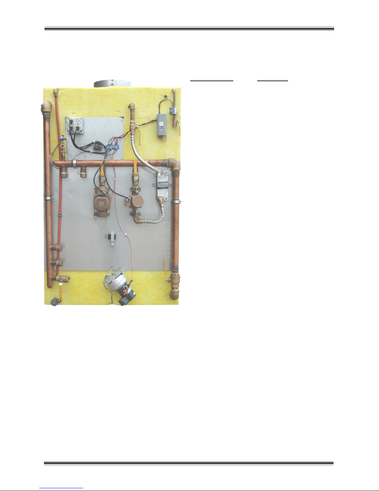
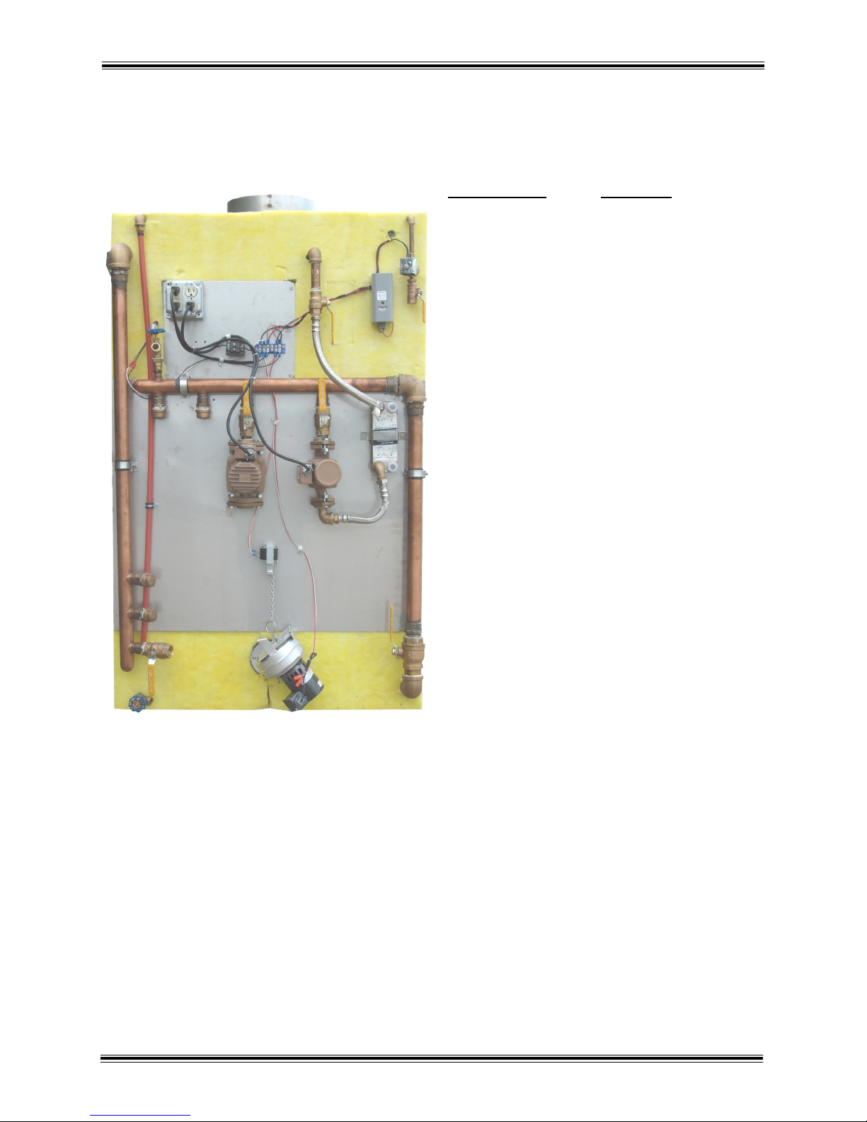
Section I 1-2 Heater Component Parts (Model H25)
Legend Part No. Description
23
1) 2000.16 Aquastat
24
2) 1100.28 Low Water Switch
3) 1100.00 Water Solenoid
3
4) 508.09 Taco 008
5) 502.08 Taco 009
6) 2000.52 Relay
22
7) 2004.00 GFCI
8) 2001.05 Damper Solenoid
9) 2002.30 130 CFM Blower
27
10) 300.02 Plate Exchanger
11) 600.10 1/2” Brass elbow
12) 810.00 1/2” Overflow pipe
13) 607.42 3/4” Male Boiler Drain Valve
14) 700.05 3/4” x 10” SS Flex Line
15) 700.18 3/4” x 18” SS Flex Line
16) 900.80 1 1/2” Copper Supply
17) 900.85 1 1/2” Copper Pump Supply
18) 900.90 1 1/2" Copper Return
19) 607.47 1 1/2” Brase Ball Valve
20) 607.45 1" Brass Ball Valve
21) 607.12 3/4" Brass Ball Valve
22) 607.00 1/2" Brass Ball Valve
23) 600.05 1/4" Brass Elbow
24) 603.04 1/4" X 4" Brass Nipple
25) 603.28 3/4” X 4” Brass Nipple
26) 600.30 3/4" Brass Elbow
27) 600.48 1 1/2” Brass Elbow
28) 1100.30 Low Water Indicator Light
27
18
11
12
28
13
20
17
2
26
7
6
20 20
5
25
21
1
15
10
4
8
14
16
19
9
27
13
HARDY MANUFACTURING CO., INC (MODEL H25) PAGE 2
Page 13
SECTION II
OUTSIDE
COVER
WATER
TANK
CONCRETE
PAD
PUMP
RUN A 4" WATERTIGHT
PIPE TO PULL WATER
AND ELECTRICAL LINES
THROUGH BETWEEN THE
FURNACE AND THE
LOCATION TO BE HEATED
OR OTHER MEANS TO
INSULATE THE PLUMBING
LINES.
INSTALLATION OF HEATER
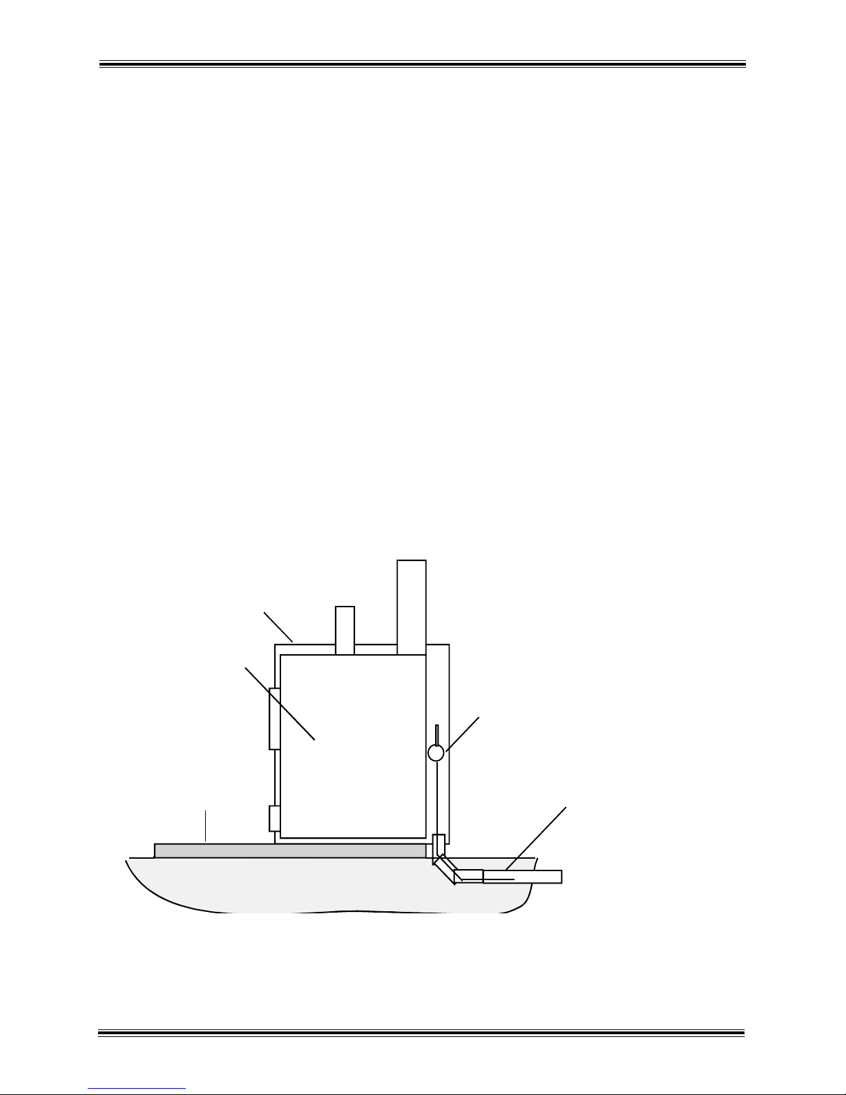
Section II 2-1 Location of Heater
The Hardy heater is designed to set outside the building to be heated. The unit must be
located a minimum of 10 feet from the building. The unit should be installed upon a
concrete pad. There are two typical options that we recommend.
Option 1 has the unit installed on concrete pad with the rear of the water tank flush with
end of the pad. We recommend the pad to be 48” wide and 53” long minimum. If you add
extra length it will allow ample concrete in front of the heater for loading wood and
removing ashes. The space between the rear of the unit and the outside cover will allow a
4 inch water tight pipe or other means to insulate the plumbing and electrical lines to run
directly into the ground. The outside cover can be removed by lifting it off the water tank on
all four corners. This will allow you easy access for the connection of the plumbing and
electrical lines.
Please see the illustration below for details.
Heater over hanging pad (not to scale)
HARDY MANUFACTURING CO., INC (MODEL H25) PAGE 3
Page 14
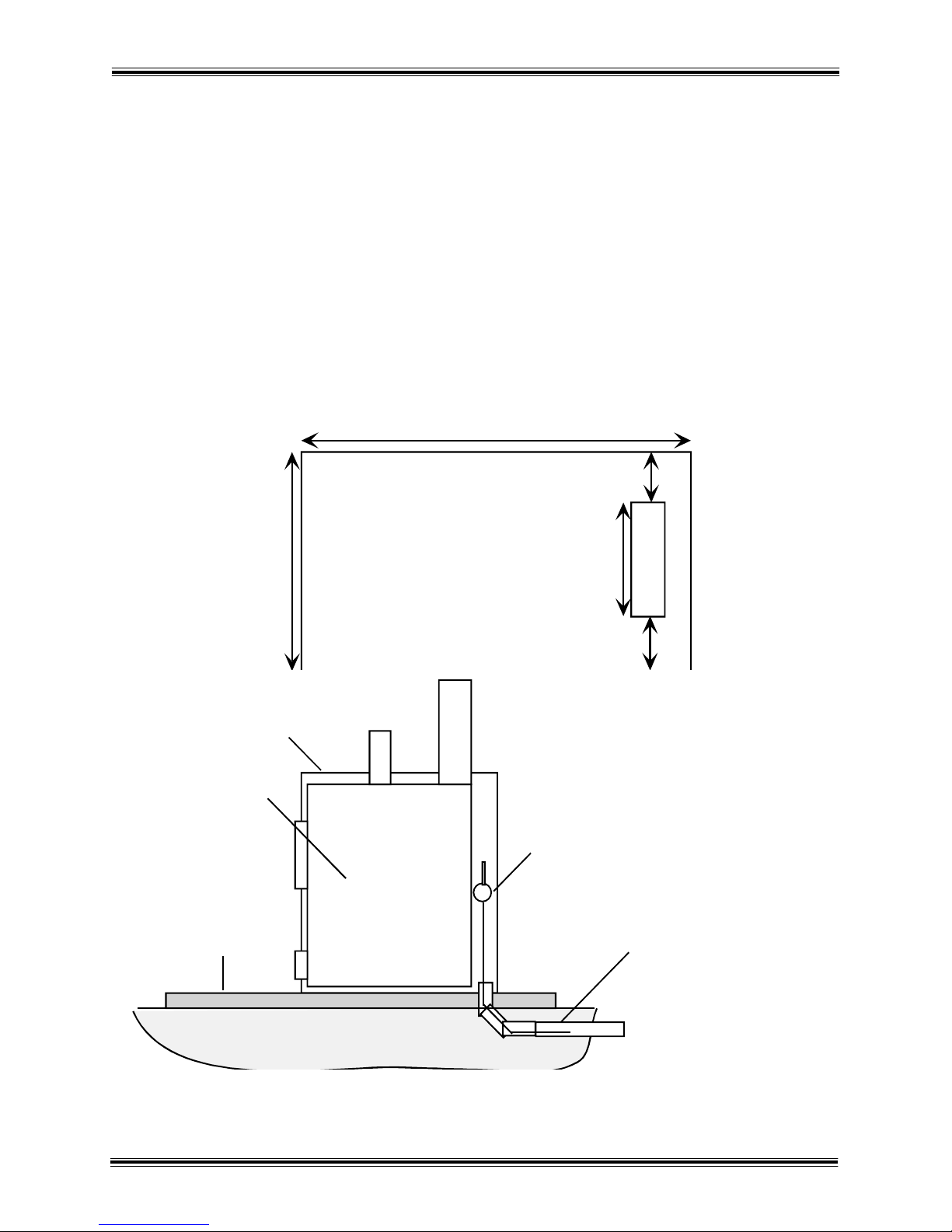
Section II 2-1 Location of Heater (continued)
65" Minimum
20"
4"
6"
14"
14"
48"
OUTSIDE
COVER
WATER
TANK
CONCRETE
PAD
PUMP
RUN A 4" WATERTIGHT
PIPE TO PULL WATER
AND ELECTRICAL LINES
THROUGH BETWEEN THE
FURNACE AND THE
LOCATION TO BE HEATED
OR OTHER MEANS TO
INSULATE THE PLUMBING
LINES.
Option 2 illustrates the unit installed on a concrete pad with cut out in the pad for
plumbing and electrical connection to run through. We recommend this pad to 48”
wide by 65” minimum long. If you add extra length it will allow ample concrete in
front of the heater for loading wood and removing the ashes. The 4” watertight pipe
or other means to insulate plumbing that runs underground exits through this cut
out to allow connections to the unit. The unit sits on the pad with the rear of the
water tank flush or even with the front side of the cutout. The outside cover of the
heater can be removed by lifting it from the water tank on all four corners. This will
allow you easy access for the plumbing and electrical connections.
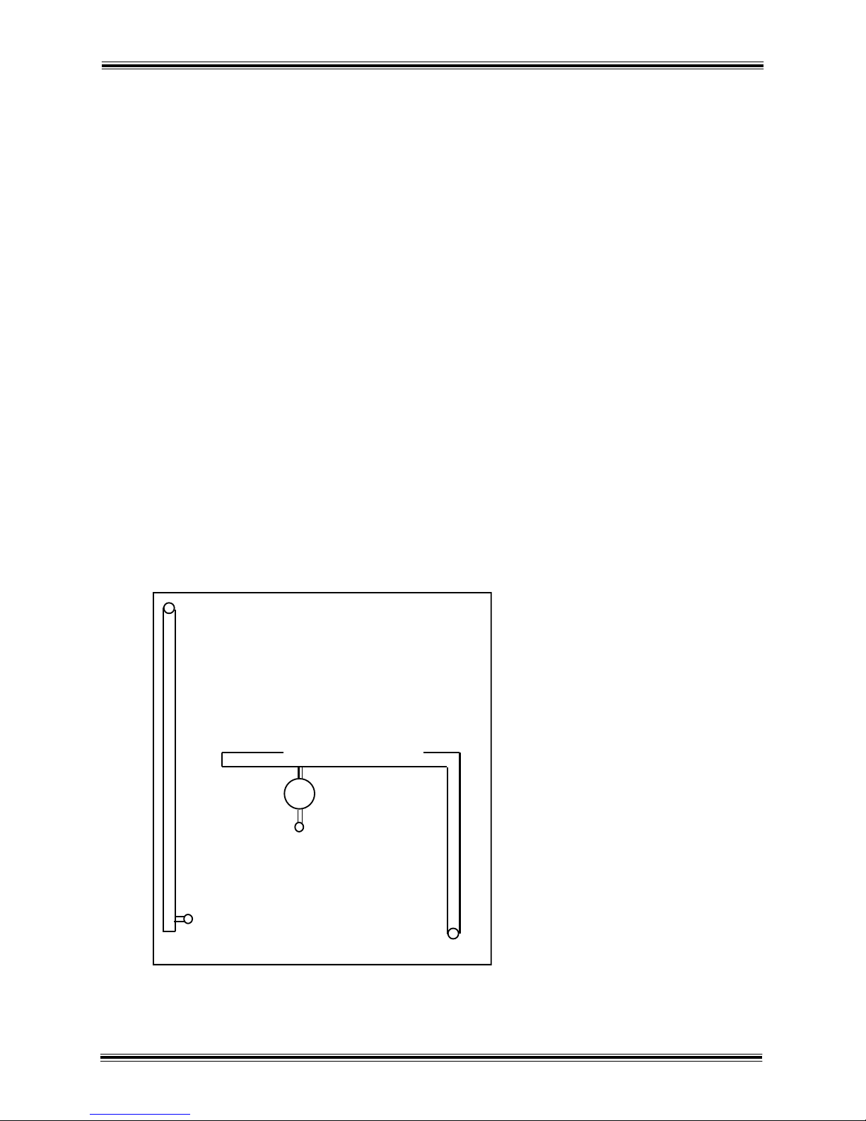
Top View of Concrete Pad
HARDY MANUFACTURING CO., INC (MODEL H25) PAGE 4
Heater on solid pad (not to scale)
Page 15

Section II 2-2 Hull Removal
After placing your new Hardy Heater upon the concrete pad, you are ready to
continue the installation process. There are two methods to gain access to the rear
of the heater to make plumbing and electrical connections.
The first and easiest method is to remove the screw holding the back door panel in
place. The door is easily removed by lifting up on the handle and taking it out.
With the back door removed, using a 5/16” wrench, remove the 8 metal screws that
are located below the back door. There are four on each side that hold the panel in
place. After the screws are removed, the panel should come out easily and allow
access to the bottom of the unit to make plumbing and electrical connections.
The second method is the removal of the entire cover. With the back and the
rectangular piece of stainless and insulation between the fire box and ash door
removed, the outside cover can be lifted up and off as seen in the picture. To
replace the cover simply repeat these steps in reverse order.
REAR FRONT
HARDY MANUFACTURING CO., INC (MODEL H25) PAGE 5
Page 16

Section II 2-3 Set-Up of Grates
First open the firebox door and remove everything from inside the heater
except the air tube, two channel beams, the welded steel baffle, and the 3/8” steel
plate. Stand the two channel beams up on the edge with flat side of channel over
against the sides of the fire box.
Slide the 3/8” steel plate in the firebox across the air tube and channel beams
under the drop down section of the fire box against the back wall. Install the grates
across the air tube and the channel beams inline and end to end in front of the 3/8”
steel plate. Stand the steel flame baffle up with the 5” support legs on the bottom
facing the front of the heater. The openings should be facing and pushed against
the drop down section. The picture below shows the proper way for grates, flame
baffle and 3/8” steel plate to be installed. These grates are designed to be turned
over if they warp.
HARDY MANUFACTURING CO., INC (MODEL H25) PAGE 6
Page 17

Section II 2-4 Location of Plumbing and Electrical Lines
The plumbing and electrical lines for your unit must be installed underground. The
water lines must be buried below the frost line to prevent freezing. The depth of the
trench varies to different regions of the country. Be completely sure about the
correct depth before the plumbing lines are installed underground.
A trench must be dug wide enough to accommodate a 4” watertight pipe or other
insulation means. All plumbing and electrical lines should be run inside the 4”
water tight pipe or other insulation means for a standard installation. If more than 1
zone is to be heated or more than 1 location is to be heated then an additional pipe,
or insulation must be installed underground.
This pipe will run from the rear of the unit to the location to be heated. Inside
the 4” watertight pipe is the water lines, thermostat wire, and electrical supply wire.
The listing below describes each line and their function.
1. One water supply line to heating system
2. One water return line from heating system
(All of these must be at least 3/4” pipe and
may require 1” because of longer distances
or some hydronic applications.)
3. One 3 conductor thermostat wire
4. One #12/2 W/G UF underground Romex wire
If more than one location is to be heated, a second 4” or single 6” watertight pipe
or other insulation means will need to be installed underground for the water lines
and thermostat wires of the second location.
HARDY MANUFACTURING CO., INC (MODEL H25) PAGE 7
Page 18

Section II 2-5 Connection of Power to Heater
This unit must be wired by a qualified electrician
in accordance with the National Electrical Code.
1. The #12/2 W/G UF wire is run from the electrical system in the house through the
4” watertight pipe or other insulation means to the heater.
2. This wire will connect to the Ground Fault Circuit Interrupter (GFCI) on the back of
the heater.
3. Install a Romex Connector in the bottom of the electrical makeup box, and insert
Romex wire through this connector.
4. Connect the black wire to the brass screw on the line side of the GFCI receptacle.
5. Connect the white wire to the silver screw on the line side of the GFCI receptacle.
6. Connect the bare copper wire to the green screw on the GFCI receptacle.
7. After the wiring is complete check the receptacle with a circuit tester to determine if
the polarity is correct, and to make sure the ground is connected. Press the test
button on the GFCI receptacle the reset button should pop out indicating the
interrupter is operating correctly. Push the reset button back to restore the GFCI
receptacle to normal operation. This test should be done monthly to insure safe
operation of the heater.
8. If moisture is allowed into Ground Fault Circuit Interrupter box, it will have a
tendency to trip unwarranted. Measures should be taken to keep the box dry.
HARDY MANUFACTURING CO., INC (MODEL H25) PAGE 8
Page 19

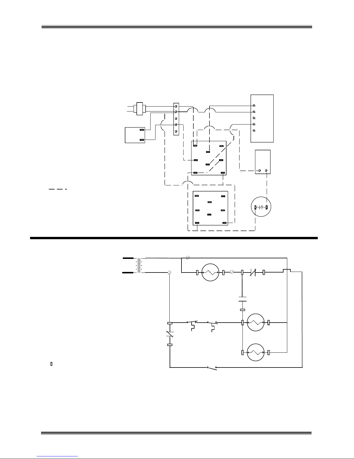
Section II 2-6 Wiring Diagrams (H25)
GROUND
FAULT
CIRCUIT
INTERRU PTER
12 0
VOL T
NEU T R AL
CONNECTION
DIAGRAM
M1
RECIR CULATOR
4
6R 3
BM
1
PM
SO L 1
GFC I
L 1
L 2
SCHEMATIC
DIAGRAM
LEGEND
GFCI GROUND FAULT CIRCUIT INTERRUPTER
R3 CIRCULA TOR PUMP RELAY
PM WATER CIRCU LATOR PUMP
M1 RECIRCULATOR PUMP
T1 DAYTON AQU ASTAT
BM1 DAM PER B LOWER MOT OR
SOL1 DAMPER SOLENOID
SOL2 WATER SOLENOI D
F1 LOW WATER SWIT CH
L1 LOW WATER LIGH T
R
F 1
L 1
SO L 2
1 2
3 4 5 6 7 8
R
BM
1
SO L 1
R 3
PM
M1
RECIR CULATOR
ZONE
CIR C ULATOR
SO L 2
F 1
T1
D ayton
ther mos t at
R B
R
B
This equipment must be installed in accordance
with the National Electrical Code.
HARDY MANUFACTURING CO., INC (MODEL H25) PAGE 9
Page 20
Section II 2-7 Plumbing Instructions
3
4
Connection to Heating System
1. The pipe that will supply the heating system is connected to the under side of the
pump. This pump is located on the right hand side of the heater (Noted by #3 in
diagram).
2. The pipe that will carry the return water from the heating system is connected to
the ¾” brass tee located at the bottom left hand corner of the heater (noted by #4
in the diagram).
Water pipes must be designed for hot water service (ex. copper,
cpvc, or Pex.) Pipes should be installed in a 4” watertight pipe or
some other type of insulating means to prevent heat loss from heater to
heating system. Use only copper, brass, or stainless steel fittings.
Do not use galvanized or black iron.
Back view of Heater
Supply Header
Pump
3) Supply to Heating System
Return
Header
4) Heating System Return
HARDY MANUFACTURING CO., INC (MODEL H25) PAGE 10
Page 21

Section II 2-8 Filling the Heater with Water
When you are ready to replace the cover, the hull can slide down over the heater. Make
sure that the condenser tank and smoke stack opening come through the outside cover.
The space between the smoke stack opening and outside cover will need a bead of
silicone applied to fill any openings. The condenser tank will also need to be sealed in this
manner. The application of silicon to these openings is illustrated by the diagram on the
next page.
Inside the firebox should be a rectangular piece of insulation and stainless steel. The
insulation fits between the firebox and ash doors. The stainless steel slides between the
two doors to protect the insulation.
After these steps, you can install the smoke stack which is a three foot section of pipe. The
trim should be slid down the smoke stack until it sits on the outside cover.
The condenser stack must also be installed in the condenser stack opening. The trim
should be slid down the smoke stack until it sits on the outside cover.
The condenser stack must also be installed in the condenser stack opening. The trim must
also sit snugly upon the outside cover.
DO NOT SEAL THE CONDENSER TANK TO THE CONDENSER TANK
LID. THIS IS THE WATER TANK VENT AND MUST NOT BE SEALED.
There are certain parts of the country that have high enough levels of chloride in the water
to be harmful to stainless steel tanks. Even though the USDA allows up to 250 parts per
million of chloride (salt) in the water as acceptable for drinking, experience has shown that
chloride levels as low as 45 parts per million will eventually cause stress corrosion cracking
in stainless steel tanks when water is heated. It is therefore required to use rain water or
bottled water with chloride content of less than 15 parts per million or test the water supply
for chloride to assure that the water supply does not exceed 45 parts per million. Call your
Hardy dealer to get a chloride test on your water supply.
Fill your heater with water through the condenser stack opening. If the chloride content of
your local water supply exceeds the specifications mentioned above and necessitates the
use of bottled or rain water, please do so to maintain the warranty of your heater.
HARDY MANUFACTURING CO., INC (MODEL H25) PAGE 11
Page 22

Section II 2-8 Filling the Heater with Water (continued)
THE HEATER MUST BE FILLED WITH WATER BEFORE STARTING A FIRE.
There is a low water switch located in a fitting on the back if the heater. This low water
switch operates a low water warning light and automatic water fill solenoid.
Condenser Stack insert’s into
condenser tank. Do not seal
between the condenser stack
and condenser tank.
Seal between the
condenser tank and
the heater hull
Insulation
Smoke stack and collar
Seal between the collar around the
smoke stack and the outer hull
Heater with Hull installed
Stainless Steel Trim
HARDY MANUFACTURING CO., INC (MODEL H25) PAGE 12
Page 23

SECTION III
CONNECTION TO CENTRAL HEATING/AC SYSTEM
3-1 Connection to Central Unit with Existing Blower Relay
CONNECTED TO ONE CENTRAL HEATING/AC SYSTEMS THAT
HAS AN EXISTING BLOWER RELAY AND ONE PUMP USING
HONEYWELL RELAY R8222D FOR THE PUMP RELAY AND THE
NEW BLOWER RELAY.
This unit must be wired by a qualified electrician
in accordance with the National Electrical Code.
1 Run a three conductor thermostat wire from the wood heater to central unit in the
house. This wire must be rated for underground use or be run inside a watertight pipe.
The colors normally are red, white, and green.
2 At the heater connect the white wire to terminal 8 of the water pump relay (R-3).
3 Connect the red wire to one side of the low temperature sensor (the round disc with
two terminals under the insulation near the center of the heater appx. 12” from the top).
This is an option that prevents the plumbing of water less than 100ºF but is not
required. If you elect not to use this option, then only a two wire conductor is required,
bypassing the low temperature sensor.
4 Connect a jumper wire from the other side of the low temperature sensor to
terminal 7 of the water pump relay (R-3) and also connect the green wire to terminal 7
of R-3. If two wires are used then one is connected to terminal 7 and the other to
terminal 8.
5 Inside the house:
A. Install the new wood heating thermostat next to the existing thermostat.
1. Remove the cover on the new home heat thermostat to mount it
on the wall. There is a round dial visible with an adjustable
pointer. This is the heat anticipator. The dial also has a series of
numbers. The pointer must be set to the highest number on the
dial. On the Honeywell model #(t 822-1016), the pointer is
turned counter clockwise as far as it can go.
6 Run a two conductor thermostat wire from the new thermostat to central unit:
A. The colors normally used are red and white.
NOTE: If you are not familiar with the control circuit of your central
unit, do not continue beyond this point. Call a heating and air
conditioning serviceman to complete the wiring. Improper wiring can
cause excessive electrical usage or cause your blower motor to over
heat and burn out.
HARDY MANUFACTURING CO., INC (MODEL H25) PAGE 13
Page 24

Section III 3-1 Connection to Central Unit
with Existing Blower Relay (continued)
7. Locate the existing 24 volt transformer:
A. One 24 volt line (hot) should run from the transformer to the existing thermostat;
1. Cut this wire and connect the wire going to the existing thermostat to
terminal 2 of R-2 (new blower relay).
2. Connect the wire running from the 24 volt transformer to terminal 1 of
R-2 and also connect the red wire of the two conductor thermostat wire
to terminal 1 of R-2.
3. Connect the white wire of the two conductor thermostat wire to the red
wire of the three conductor wire.
8. Locate the other 24 volt line (common) coming from the transformer:
A. Splice a white jumper wire to this wire.
B. Connect the other end of the white jumper wire to terminal 8 of R-2.
C. Also connect the white wire of the three conductor thermostat to
terminal 8 of R-2.
D. Connect the green wire of the three conductor thermostat wire to
terminal 7 of R-2.
E. Also connect a jumper wire from terminal 7 of R-2 to terminal 6 of R-2.
9. Locate the existing central unit blower relay (R-1):
A. Locate the wire running from the existing thermostat to the blower relay coil.
Disconnect this wire from the existing blower relay coil and connect it to terminal
5 of the new blower relay R-2.
B. Connect a jumper wire from the existing blower relay coil (the point that you just
disconnected) to terminal 4 of relay R-2.
10. If all connections are made properly and the water in the wood heater is hot, the unit
should be ready for operation. NOTE: This is a general diagram. You may have to
make various changes according to how your unit is wired.
A. Insure that the compressor on a heat pump or A/C unit does not run when the
wood system is running.
B. Insure that the gas burner, oil burner, or electric elements do not come on when
the wood system is running.
C. Insure that only one speed of the blower motor can be energized at one time.
If more than one speed is energized at the same time, the blower motor will burn
out.
D. Insure that the Volt Amp rating of the existing 24 volt transformer is not
exceeded when the relays in the wood heating system are energized.
HARDY MANUFACTURING CO., INC (MODEL H25) PAGE 14
Page 25
Section III 3-1 Connection to Central Unit
R1 EXISTING BLOWER RELAY
R3 PUMP CONTROL RELAY
R2 NEW CONTROL RELAY
T2 NEW THERMOSTAT
LTS LOW TEMPERATUR E SENSOR
FS EXISTING THERMOSTAT
TC TERMINAL STRIP "C" CONNECTION
TR TERMINAL STRIP "R" CONNECTION
TG TERMINAL STRIP "G" CONNECTION
R EXISTING THERMOSTAT CONNECTION
G EXISTING THERMOSTAT CONNECTION
QUICK CONNECT TERMINALS
LEG END
1
2
3
4
5
6
7
8
R
C
G
W
L1
L2
24 VOLTS
R
C
G
W
1
2
3
4
5
6
7
8
EXIS TING
T RA NSF ORMER
EXIS TING
THE RMOSTAT
EXIS TING
BLOW ER RE LAY
NE W
RELAY
NEW
THE RMOSTAT
LOW
TE MPERATUR E
SE NSOR
CIRCUL AT OR
PUMP RELA Y
L1
L2
11
5V
2
4V
TR
TC
R1
R2
R3
T2
LTS
FS
1
2
4 5
6
7
8
7
8
R2
R2
R2
TG
CONNECTION DIAGRAM
SCHEMATIC DIAGRAM
G
R
LOW VOLTAGE FIELD WIRING
with existing Blower Relay (continued)
HARDY MANUFACTURING CO., INC (MODEL H25) PAGE 15
Page 26
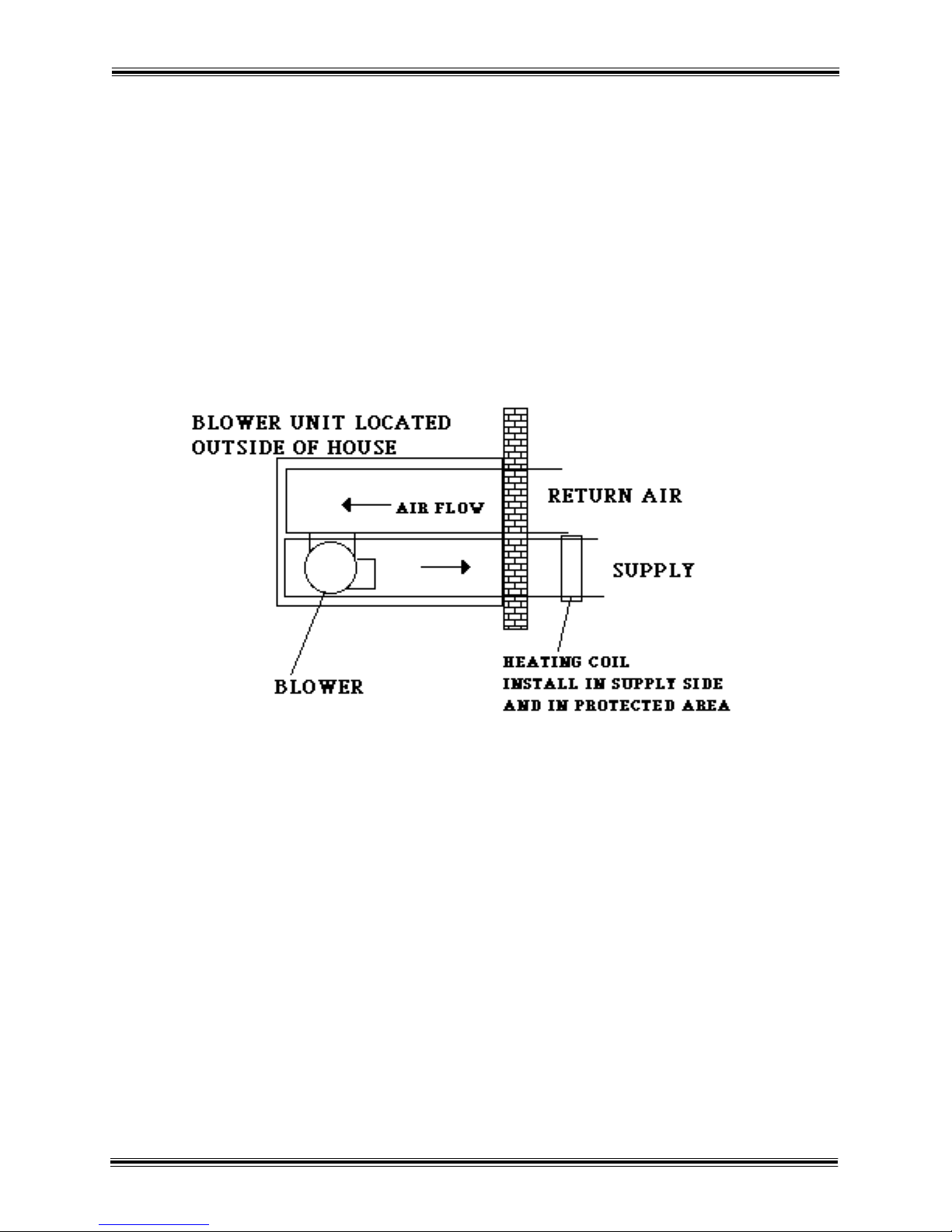
Section III 3-2 Location of Heating Coil
The following diagrams and pictures
on this page and the following page
show various methods of installing
the heating coil in forced air system.
HARDY MANUFACTURING CO., INC (MODEL H25) PAGE 16
Page 27
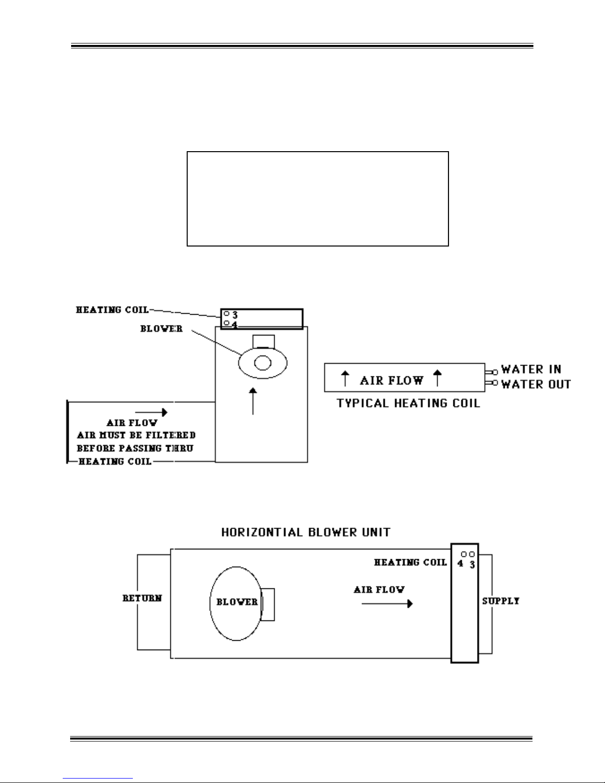
Section III 3-2 Location of Heating Coil (continued)
3) SUPPLY TO HEATING SYSTEM
4) HEATING SYSTEM RETURN
HARDY MANUFACTURING CO., INC (MODEL H25) PAGE 17
Page 28

SECTION IV
CONNECTION TO HYDRONIC HEATING SYSTEMS (BASEBOARD)
4-1 Connection to Hydronic System
with Existing 24 Volt Transformer
ONE PUMP ON THE WOOD HEATER
USING HONEYWELL RELAY R8222D.
This unit must be wired by a qualified electrician in
accordance with the National Electrical Code.
1. Run two conductor thermostat wire from the wood heater to the existing heating
system in the house. This wire must be rated for underground use or be run inside
a pvc pipe. The colors normally used are red and white.
2. At the heater, connect the white wire to terminal 8 of the water pump. (R-3)
3. Connect the red wire to terminal 7 of the water pump relay. (R-3)
4. In the house locate the existing pump relay. Connect the red wire of the two
conductor thermostat wire to the coil of the pump relay, that is fed by the existing
thermostat.
5. Connect the white wire of the two conductor thermostat wire to the coil of the
pump relay on the side that is fed from the common side of the transformer.
HARDY MANUFACTURING CO., INC (MODEL H25) PAGE 18
Page 29

Section IV 4-1 Connection to Hydronic System
1
2
3
4
5
6
7
8
CONNECTION DIAGRAM
LOW VOLTAGE
FIELD WIRING
P M
EXISTING PUMP
MOTOR
EXISTING PUMP
RELAY
EXISTING
24 V OLT
TRA NSFORMER
EXISTING
THERMOSTA T
CIRCULA TING PUMP
RELA Y ON FURNACE
SCHEMATIC DIAGRAM
L1
L2
R1
R1
R3
TX1
24V
T1
LEGEND
TX1 EXISTING TRA NSFORMER
T1 EXISTING THERMOSTA T
PM EXISTING PUMP MOTOR
R1 EXISTING PUMP RELA Y
R3 CIRCULA TOR PUMP RELA Y
P M
with Existing 24 Volt Transformer (continued)
HARDY MANUFACTURING CO., INC (MODEL H25) PAGE 19
Page 30
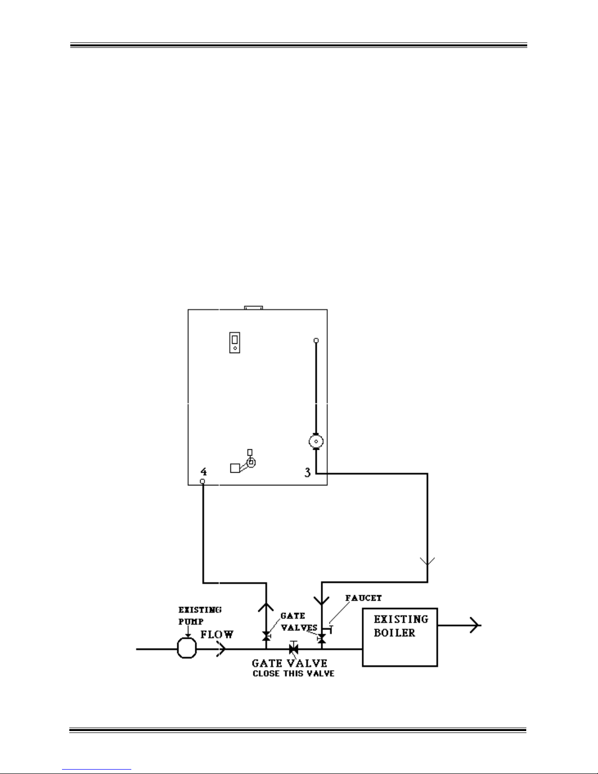
Section IV 4-2 Typical Diagram for Plumbing
Hydronic System
Water Pipes must be designed for hot water service (ex. Copper, cpvc, or
polybutylene.) Pipes should be installed in a 4” watertight pipe or some other
type of insulating means to prevent heat loss from heater to heating system. Use
only copper, brass, or stainless steel fittings. Do not use galvanized or black iron.
Turn off the makeup water for the existing system. Manual filling of the wood heater
or the electric fill option will supply makeup water for the wood heater and the
existing hydronic. Close all automatic air vents on the existing system.
Valving arrangement may
be located on suction side
of pump if space is limited
on pump discharge.
HARDY MANUFACTURING CO., INC (MODEL H25) PAGE 20
Page 31

1
2
cold
hot
SECTION V
PLUMBING OPTIONS FOR DOMESTIC WATER
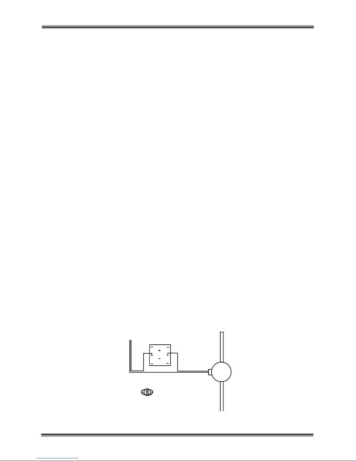
5-1 Plate Heat Exchanger for Domestic Hot Water
To add domestic hot water to the H25 model heater, a plate heat exchanger can
be added into the recirculating pump circuit. This plate heat exchanger will provide
preheated water to the domestic hot water. Mount a plate heat exchanger on the
back of the heater and connect it as shown in the following picture. The Taco 008
pump will circulate heater water through the plate continuously. The cold water
supply will be connected to the top right port on the plate heat exchanger. The
bottom right port will feed into the cold side of your water heater.
Cold water feed will connect to the top
port of the heat exchanger. The hot
water will return from the bottom port
of the heat exchanger to the cold water
inlet of the water heater
HARDY MANUFACTURING CO., INC (MODEL H25) PAGE 21
1
2
!
WATER TEMPERATURE
OVER 125° CAN CAUSE
SEVER BURNS INSTANTLY
DANGER
Page 32

SECTION VI
HEATER OPERATION
6-1 Firing the Heater
Start the fire as you would in any other wood heater. Do not use petroleum
products to start a fire. After you get an initial fire started, always stack the wood in
the fire box straight. Do not cross the wood because this can cause the fire to go
out. Any time you add wood, fill the fire box completely. The heater will burn only as
much wood as is needed to keep the water hot.
CAUTION: ALWAYS OPEN THE BOTTOM DOOR BEFORE YOU OPEN THE TOP DOOR.
6-2 Water Temperature
In the back of the heater is a hot water aquastat. When power is supplied to the
terminal strip the aquastat will send power to the damper system and draft blower
as long as the heater water is below the setpoint of the aquastat. This setpoint is
factory set at 170 to 180 degrees. If your heater does not operate correctly at these
temperatures contact your authorized Hardy dealer for temperature adjustments.
6-3 Wood Usage
Never leave the doors open unattended because it will cause excessive wood
consumption and could possibly damage the heater. If the heater is burning more
wood than usual, check the seal around the front doors. If the seal is bad it will
need replacing. Call your local Hardy dealer and order rope and silicone for the
firebox or ash door. The fire in the heater must be out to seal the door. With door
still mounted on the heater, scrape the old silicone out of the groove. Run a small
bead of silicone in the groove of the door. Start installing the rope at the top edge of
the wide groove (next to the hinges) running down the hinge side and continue
around the door. Make sure the ends of the rope join together in the final corner,
cut off any excess rope. Fill in the corners with silicone.
6-4 Moisture in the Firebox
On a new heater or the first time you start a fire each year, you will probably think
you have a leak in the firebox. The firebox walls will sweat and water will run down
the side. This can also happen if the water temperature drops below 100’F in the
winter. This drop in temperature can be caused by improper burning due to
stopped up grates. If you see moisture in the firebox, wait three days before you
get alarmed. If it continues, check to see if you are burning green wood. Green
wood will create a lot of moisture in the firebox, even to the extent that water can
get as high as an inch or two in the ash pan.
HARDY MANUFACTURING CO., INC (MODEL H25) PAGE 22
Page 33

If you still think you have a leak in your heater, remove all wood and ashes from the
heater. Let it set a couple of days with doors closed. Then open the ash door. If you
have a leak, water will run out of the ash box.
6-5 Improper Burning
If the fire is not burning properly, remove all of the ashes and wood from the heater.
Check to see if the grates are stopped up. Check the air intake at the back of the
heater to insure it is clear of ashes. Lift the damper lid to check for ashes. Check to
see if the force air blower is running. If you have made these checks and the fire
will not burn properly, remove the smoke stack and check for creosote buildup.
Look down the smoke stack into the firebox to check for creosote buildup. Looking
through the firebox door you will see an opening on the lower left and lower right
corners just above the grates. These holes need to remain open for proper burn.
The plate in the center is a loose plate that can be removed through the firebox
door, cleaned, and reinstalled. These steps should correct the problem.
6-6 Ash Removal
Ashes must be removed before they build up to the level of the grates. Failure to
keep the ash bin cleaned out will result in warped grates. The buildup of ashes in
the firebox should be checked at least once a week. Allow the fire to burn down
until the grates can be seen. This insures that all of the grates are clear. Failure to
do this will cause your heating system to stop working and the grates to warp. If the
grates warp slightly, they can be turned over and allowed to straighten out.
HARDY MANUFACTURING CO., INC (MODEL H25) PAGE 23
Page 34
SECTION VII
1
2
3
4
5
6
7
8
115 volts
Relay p/n H2000.52
Low Temperature Sensor
p/n H2000.36
Pump
SERVICE INFORMATION
7-1 Water Circulation System
LOW TEMPERATURE SENSOR, P/N H2000.36 – (WARNING: When working with
electrical circuits, use caution to avoid electrical shock) – This sensor can be wired
in the home heat thermostat circuit to prevent the pump on the heater from running
when the water in the wood heater is not hot. The sensor has a set of contacts that
close when the water rises to 110ºF and open when the water drops to 90ºF.
WATER PUMP RELAY, P/N H2000.52 - (WARNING: When working with electrical
circuits, use caution to avoid electrical shock) – This is a Honeywell DPDT relay
with a 24 volt coil. Terminal 4 and 6 (normally open contacts) are used to turn on
the water pump. Control voltage (24 volts) connected at terminals 7 and 8 routed
through a home thermostat energizes the relay.
WATER PUMP FOR HEATING SYSTEM, Taco 009 pump P/N H502.00 - (WARNING:
When working with electrical circuits, use caution to avoid electrical shock) – with
bronze body. If the pump will not run, first unplug the power cord then check the
water pump relay. The relay can be bypassed by disconnecting the wire from
terminal 6 and then connecting to terminal 5 (terminals 4 to 5 is normally closed)
remove the thermostat wire from terminal 8 and plug the power cord back in. This
should supply 115 vac directly to the pump. If the pump will still not run, unplug the
power cord. Remove the four bolts holding the pump to the pump housing. Remove
the cartridge from the pump. Spin the impeller by hand to see if the cartridge is
locked up. If the impeller will not spin, replace the cartridge. If the impeller will spin,
it may have been temporarily stuck (reassemble and try again) or the problem is the
electrical winding or capacitor. Use an ohm meter to check the winding and
capacitor. If the capacitor is defective, replace it. If the electrical winding is
defective, replace the complete pump.
HARDY MANUFACTURING CO., INC (MODEL H25) PAGE 24
Page 35

Section VII 7-2 Temperature Control System
1
2 3 4 5 6 7 8
BM
1
SO L
1
Dayton
Aquastat
120 volts
Neutral
R e d
Bl ue
DAMPER THERMOSTAT, Dayton - (WARNING: When working with electrical circuits, use
caution to avoid electrical shock) – This thermostat has a probe that is in a well in the water tank
of the wood heater. It has a set of contacts that open on a temperature rise and close on a temperature
fall. This thermostat is normally set at 170ºF to 180ºF. It controls the damper solenoid and the forced
air draft. If the damper solenoid and forced air draft will not operate, place a jumper wire across the
terminal strip from #4 to #5. If they operate when the correct terminals are jumpered out, and the
temperature of the water in the heater is below the set point on the thermostat, the thermostat is
defective. Do not leave the jumpers across the terminal strip because the heater will overheat.
DAMPER SOLENOID, P/N H 2001.05 - (WARNING: When working with electrical circuits,
use caution to avoid electrical shock) – This solenoid lifts the cover off the intake to the forced air
draft blower. The solenoid is controlled by the damper thermostat. It should lift the cover when the
forced air blower comes on and drop the cover.
FORCED AIR DRAFT BLOWER, P/N H2002.28 - (WARNING: When working with electrical
circuits, use caution to avoid electrical shock) – This blower supplies air to the fire box when the
damper thermostat calls for heat. If the blower wheel or the intake to the blower is clogged, the
blower will not deliver the proper amount of air to the fire. The blower can be disassembled and
cleaned. Be sure to seal the blower motor back to the blower housing if the blower is disassembled.
The motor should be oiled at the beginning of each heating season. When the heater is not in use, the
power cord for the blower should be unplugged.
HARDY MANUFACTURING CO., INC (MODEL H25) PAGE 25
Page 36

SECTION VII 7-3 Preseason Heater Maintenance
Each year before the heating season begins,
you should check your heater to insure
that everything is ready for the heating season.
1. WATER QUALITY – The Hardy Heater is designed not to loose heater water through
evaporation. At times during the year, accidental overheating can occur, and the water will
evaporate. The evaporation causes a concentration of chlorides (salts) and other minerals.
To protect your heater from this build up of chlorides (salts) and other minerals, we
recommend to drain your heater each year at time of startup for the heating season and
refill with rain water or bottled water with a chloride concentration of less than 15 parts per
million. This will add to the life of your stainless steel tank.
2. DAMPER AND DRAFT SYSTEM – When you plugged in the power cord, the damper
solenoid should have opened the draft lid on the draft blower. The forced air draft blower
should also have come on. If both of these components are working correctly, unplug the
power cord. Open the clean out lid beside the draft blower and check for any build up of
ash, tar, or any other material that could restrict the amount of combustion air entering the
heater. Check the seal on the clean out lid to assure a good air tight seal is still
established. Lift the damper lid on the draft blower and inspect the blower wheel for any
build up of lint, dust, creosote, or any other substance that could effect the performance of
the draft blower. Spray the damper lid hinge, and the damper solenoid plunger with WD-40,
or its equivalent. Oil the draft blower motor with electric motor oil, or 10 weight non
detergent motor oil. Do no use WD-40, or machine oil. Check the grates inside the heater
to see if there is any ash build up or if the grates are warped. If a grate does warp, lift that
grate up and turn it over. Also at this time check the smoke stack for blockage.
3. WATER PUMP – Unplug the power cord going to the water pump. Close the valve
above the water pump and the return water valve at the bottom of the heater. Remove the
pump motor from the pump housing by removing the four bolts in the pump housing.
Remove the impeller cartridge assembly from the pump housing. Check the impeller to
determine if it is free by spinning the impeller in the cartridge. Check the pump housing for
rust or any other build up that could impede the flow of water. Reassemble the water pump,
making sure the “O” ring in the cartridge is seated right. Once the pump is reinstalled, open
the water valve above the pump and the return valve.
HARDY MANUFACTURING CO., INC (MODEL H25) PAGE 26
Page 37
Section VII 7-5 Trouble Shooting Guide H25
COMPLAINT AREA OF TROUBLE POSSIBLE CAUSES CORRECTIVE ACTION
NO HEAT
Main power
supply and
ground fault
interrupter
receptacle “OK”
Water
temperature is
“HOT”
Pump Performance Unplug pump and bypass relay by tying relay wires #4 and #6
together. Plug pump back in.
Pump does not run 1 Defective pump
cartridge
2 Defective pump
capacitor
3 Defective pump
motor winding
Pump does run 1 Defective 24 volt
transformer
2 Defective wall
thermostat (heater)
3 Defective low
temperature sensor
4 Defective pump relay
1 Unplug pump. Remove pump.
Pull cartridge from pump and
spin impeller by hand. If
impeller will not spin, replace
cartridge.
2 Use Ohmmeter. When the
meter is connected to the
capacitor, the needle should
jump to “0” ohms and slowly
drift back to infinity. Replace
if defective.
3 Disconnect the wires
connected to the motor
terminals to test the motor
independent of electrical
connections. Check for
ground and continuity with
ohmmeter The insulator of the
windings should show no
breakage. If it does, replace
pump
1 Located at existing central
unit. If 115/120 volts is being
supplied to primary side
check for 24 volts on
secondary. If 24 volts not
present, replace transformer.
2 Located inside home.
Remove cover. Check for 24
volts. Level the mounting
base. Blow dust from sensing
bimetal. Adjust heat
anticipator. See owners
manual connection
instructions.
3 Remove wires on sensor and
connect to each other to
bypass. If pump runs replace
low temperature sensor.
4 Check relay terminals #7 &
#8 for 24 volts. If 24 volts is
present, use ohmmeter to
check contacts. Connect
ohmmeter to terminals #4 &
#6. If no reading replace
relay.
HARDY MANUFACTURING CO., INC (MODEL H25) PAGE 27
Page 38

Section VII 7-5 Trouble Shooting Guide H25
COMPLAINT AREA OF TROUBLE POSSIBLE CAUSES
NO HEAT
Main power
supply and
ground fault
interrupter
receptacle “OK”
Water
temperature is
“COLD”
Aquastat
Damper Solenoid 1 Defective damper
Forced Air Draft Blower
Motor
Ash Bin 1 Ash buildup in ash bin 1 Clean out ash bin. Ash bin
1 Defective Aquastat 1 Place a jumper wire across
solenoid
Defective blower motor
1 Defective electrical
wiring
2 Air passage stoppage
3 Blower wheel clogged
CORRECTIVE ACTION
terminal #4 on the
terminal strip. If blower and
Damper solenoid operates,
replace aquastat
1 When bypassing aquastat if
solenoid does not lift the lid
off the intake to the forced
air draft blower, replace the
solenoid.
1 Make sure all connections
are secure.
2 Clear air passages in
cleanout and damper blower
outlets
3 Clear blower wheel of any
lint, ashes or creosote build
up.
should be cleaned out each
week. Ash build up on grates
can cause grates to warp. If
grates warp they can be
turned over and allowed to
straighten.
Excessive Wood
Usage
Heater Stack 1 Ash and Creosote
Buildup
Firebox 1 Open
2 Defective door seals
3 Damper lid not closing
properly
4 T & P valve leaking
1 Clean heater stack of any ash
and creosote build up.
1 Close all doors and make
sure they are securely
fastened.
2 If the seal is bad it will need
replacing. Call your local
Hardy dealer to request rope
and silicone. See owners
manual, (heater operation
section) for replacing door
seals.
3 Remove any obstructions
causing lid not to close
properly.
4 If leaking, replace.
HARDY MANUFACTURING CO., INC (MODEL H25) PAGE 28
Page 39
Section VII 7-5 Trouble Shooting Guide H25
COMPLAINT AREA OF TROUBLE POSSIBLE CAUSES CORRECTIVE ACTION
Improper
Burning
Remove all the
ashes and wood
Grates
Air intake 1 Air intake stopped up 1 Clean air intake at back of
Damper Chamber 1 Damper chamber
Forced Air Blower 1 Forced air blower not
Smoke Stack 1 Smoke stack stopped
Baffle 1 Baffle blocked 1 Clean out fire box and check
Fire 1 Fire goes out 1 If fire goes completely out
1 Grates stopped up
stopped up
running
up
1 Clear grates of ash buildup.
If grates are warped, turn
them over and allow to
straighten.
heater of any obstructions.
1 Lift damper lid and check
for obstructions.
1 If not running see No Heat
section in this guide
1 Remove smoke stack and
check for creosote build up.
openings to baffle plate
when damper is closed,
check the holes in the
damper lid for obstructions,
clean out.
Moisture
In Fire Box
Firebox 1 Yearly startup
2 Green Wood
1 The firebox walls will sweat
and water will run down the
sides. This should clear up in
a few days.
2 Green wood will create
excess moisture.
HARDY MANUFACTURING CO., INC (MODEL H25) PAGE 29
Page 40

THIS PAGE INTENTIONALLY LEFT BLANK
HARDY MANUFACTURING CO., INC (MODEL H25) PAGE 30
Page 41
HARDY MANUFACTURING CO., INC (MODEL H25) PAGE 31
Page 42
Section I 1-2 Heater Component Parts (Model H25)
Section VII Repair Parts
Legend Part No. Description
23
1) 2000.16 Aquastat
24
2) 1100.28 Low Water Switch
3) 1100.00 Water Solenoid
3
4) 508.09 Taco 008
5) 502.08 Taco 009
6) 2000.52 Relay
22
7) 2004.00 GFCI
8) 2001.05 Damper Solenoid
9) 2002.30 130 CFM Blower
27
10) 300.02 Plate Exchanger
11) 600.10 1/2” Brass elbow
12) 810.00 1/2” Overflow pipe
13) 607.42 3/4” Male Boiler Drain Valve
14) 700.05 3/4” x 10” SS Flex Line
15) 700.18 3/4” x 18” SS Flex Line
16) 900.80 1 1/2” Copper Supply
17) 900.85 1 1/2” Copper Pump Supply
18) 900.90 1 1/2" Copper Return
19) 607.47 1 1/2” Brase Ball Valve
20) 607.45 1" Brass Ball Valve
21) 607.12 3/4" Brass Ball Valve
22) 607.00 1/2" Brass Ball Valve
23) 600.05 1/4" Brass Elbow
24) 603.04 1/4" X 4" Brass Nipple
25) 603.28 3/4” X 4” Brass Nipple
26) 600.30 3/4" Brass Elbow
27) 600.48 1 1/2” Brass Elbow
28) 1100.30 Low Water Indicator Light
27
18
11
12
28
20
13
17
2
26
7
6
20 20
5
25
21
1
15
10
4
8
14
16
19
9
27
13
HARDY MANUFACTURING CO., INC (MODEL H25) PAGE 32
 Loading...