

Hardware MB-GATEWAY User Manual

Appendix
Appendix
Appendix
ApplicAtion ExAmplEs
A
A
A
In this Appendix...
Example 1: Using Modbus Poll to MB-GATEWAY with DL06 Slave ............................ A-2
Items needed for this example: ����������������������������������������������������������������������������������� A-2
Step 1: Connect the MB-GATEWAY serial port to the DL06 secondary
communications port� ������������������������������������������������������������������������������������� A-2
Step 2: Configure the DL06 PLC serial port and MB-GATEWAY serial port� ����������������� A-3
Step 3: Connect to the MB-GATEWAY using the Modbus Poll simulator software� ������ A-7
Example 2: Using Modbus Poll to MB-GATEWAY with CLICK Slave ........................ A-11
Items needed for this example: ��������������������������������������������������������������������������������� A-11
Step 1: Connect the MB-GATEWAY serial port to Port 3 of the CLICK PLC� ��������������� A-11
Step 2: Configure the CLICK serial port and MB-GATEWAY serial port� ��������������������� A-12
Step 3: Connect to the MB-GATEWAY using the Modbus Poll simulator software� ���� A-18
Example 3: Using P3000 as Master (Client) to MB-GATEWAY with CLICK Slave. ... A-24
Step 1: Connect CLICK to the MB-GATEWAY as shown in example 2� ���������������������� A-24
Step 2: Connect P3000 CPU (P3-550) to MB-GATEWAY via Ethernet Switch and
Two Ethernet Cables� ������������������������������������������������������������������������������������ A-24
Step 3: Configure the MRX instruction to read data from the MB-GATEWAY� ����������� A-28
Example 4: DirectLogic 06 (H0-ECOM100) as Master (Client) to
MB-GATEWAY with Mulitple GS Drives as Slaves. .................................................... A-29
Step 1: Set up Peer to Peer Configuration ����������������������������������������������������������������� A-30
Step 2: Set the Serial Port Configuration ������������������������������������������������������������������� A-31
Step 3: Set the Communication Parameters �������������������������������������������������������������� A-31
Step 4: Using Automatic Reads ���������������������������������������������������������������������������������� A-32
Step 5: Access the Automatic Read Data ������������������������������������������������������������������� A-33
Step 6: Read and Write from the DL06 ��������������������������������������������������������������������� A-36
Example 1:
Internally Connected
Ready to send (+) (RS-422/485)
Appendix A: Application Examples
Using Modbus Poll to MB-GATEWAY with DL06 Slave
This example will illustrate how to use Modbus Poll, which is a PC based Modbus Master
simulator tool, to connect through the MB-GATEWAY to a DL06 PLC via 2 wire RS-485.
Items needed for this example:
• MB-GATEWAY
• DirectLogic 06 PLC (any model)
• PC with Modbus Poll installed (free demo is available at www.modbustools.com)
• Small length of Belden 9842 or equivalent cable
• ZL-CMA15 ZipLink communication port adapter, 15-pin high density female to terminal block
• Ethernet switch and cables to connect from the PC to MB-GATEWAY
A
2
3
4
5
6
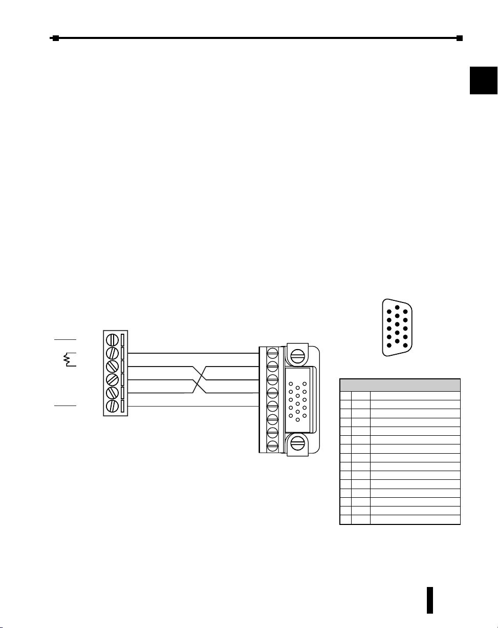
Step 1: Connect the MB-GATEWAY serial port to the DL06 secondary
communications port.
Using the short length of Belden 9842, connect the MB-GATEWAY to the DL06 Port 2 as
shown:
RS-422/RS-485
Gateway
GND
RX+
RX-
TX-
TX+
GND
(Gateway contains a
120Ω Termination Resistor
between RX+ and RX-)
GND
ZL-CMA15
to DL06 Port2
TX+
RX+
TXRX-
NOTE: If using a connector
other than ZL-CM15 or
ZL-CMA15L, jumpers must
be installed on the
PLC side:
Pin 11 to 14
Pin 12 to 15
DL06 Port 2 Pin Descriptions
1
5V Power (+) connection
2
TXD
3
RXD
4
RTS
5
CTS
6
RXD
7
0V
8
0V
9
TXD+
10
TXD-
11
RTS+
12
RTS-
13
RXD+
14
CTS+
15
CTS-
6
1
11
10
5
15
15-pin Female
D Connector
Transmit data (RS-232C)
Receive data (RS-232C)
Ready to send (RS-232C)
Clear to send (RS-232C)
Recieve data (-) (RS-422/485)
Power (-) connection (GND)
Power (-) connection (GND)
Transmit data (+) (RS-422/485)
Transmit data (-) (RS-422/485)
Ready to send (-) (RS-422/485)
Recieve data (+) (RS-422/485)
Clear to send (+) (RS-422/485)
Clear to send (-) (RS-422/485)
7
8
9
10
11
12
13
14
A
B
C
MB-GATEWAY-USER-M Hardware User Manual, 1st Ed. Rev. H 02/21
D
A-2
Appendix A: Application Examples
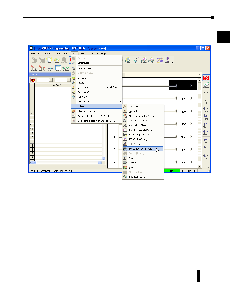
Step 2: Configure the DL06 PLC serial port and MB-GATEWAY serial port.
Connect to the DL06 PLC with DirectSoft. Go to the PLC pulldown and select Setup >
Setup Secondary Comm. Port as shown:
A
2
3
4
5
6
7
8
9
MB-GATEWAY-USER-M Hardware User Manual, 1st Ed. Rev. H 02/21
10
11
12
13
14
A
B
C
D
A-3
Appendix A: Application Examples
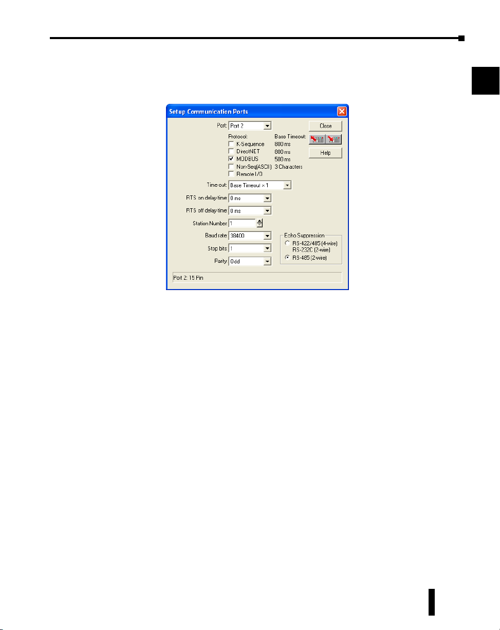
Setup the port as shown for Modbus protocol, 38400 baud rate, Odd parity, 1 Stop bit and
Station Number 1. Match everything else as shown. Note the Station Number configured in
the PLC. Once this has been done, click on the icon on the upper right hand side with the
arrow pointing to the PLC to save the settings in the PLC.
A
2
3
4
5
6
7
8
9
MB-GATEWAY-USER-M Hardware User Manual, 1st Ed. Rev. H 02/21
10
11
12
13
14
A
B
C
D
A-4
Appendix A: Application Examples
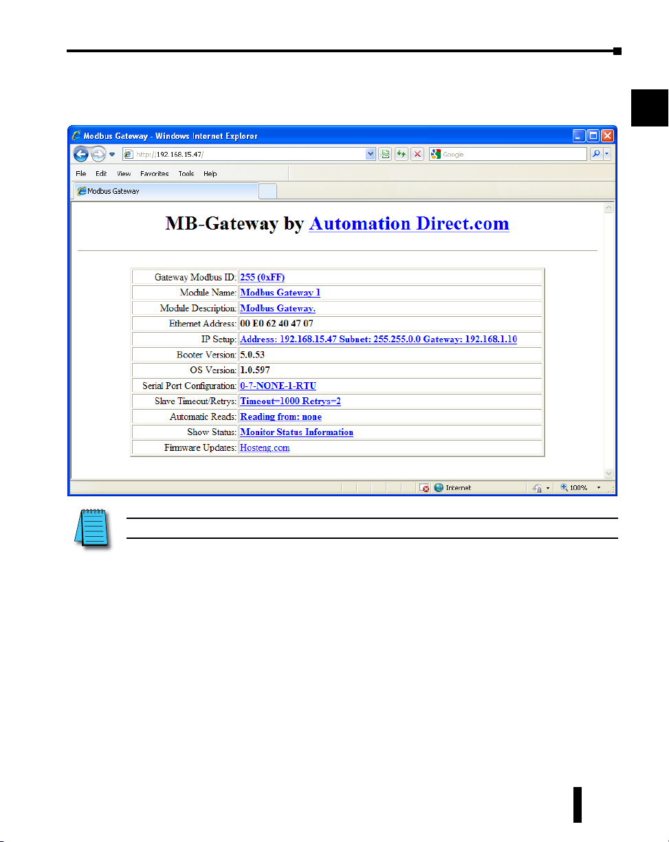
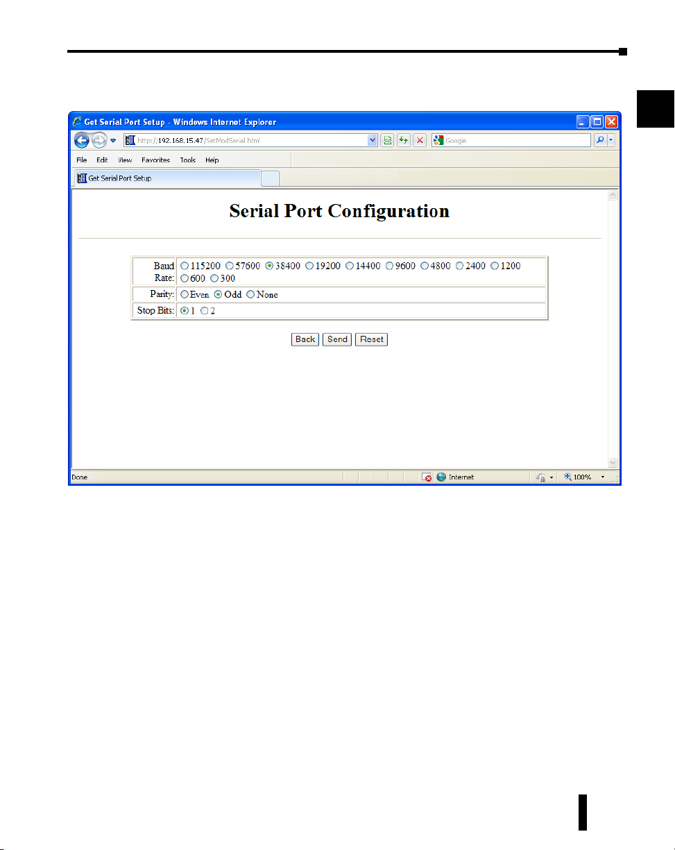
In order to match the serial port settings of the DL06 to the MB-GATEWAY open up a web
browser, such as Internet Explorer, and enter in the IP address of the MB-GATEWAY to
access the main screen as shown:
A
2
3
4
5
6
7
8
9
For instructions on connecting with a web browser see NetEdit Configuration section in Chapter 3.
MB-GATEWAY-USER-M Hardware User Manual, 1st Ed. Rev. H 02/21
10
11
12
13
14
A
B
C
D
A-5
Appendix A: Application Examples
Click on the link to the right of “Serial Port Configuration” and set up the window to match
the DL06 PLC port and then click on the Send button to save the settings:
A
2
3
4
5
6
7
8
9
MB-GATEWAY-USER-M Hardware User Manual, 1st Ed. Rev. H 02/21
10
11
12
13
14
A
B
C
D
A-6
Appendix A: Application Examples
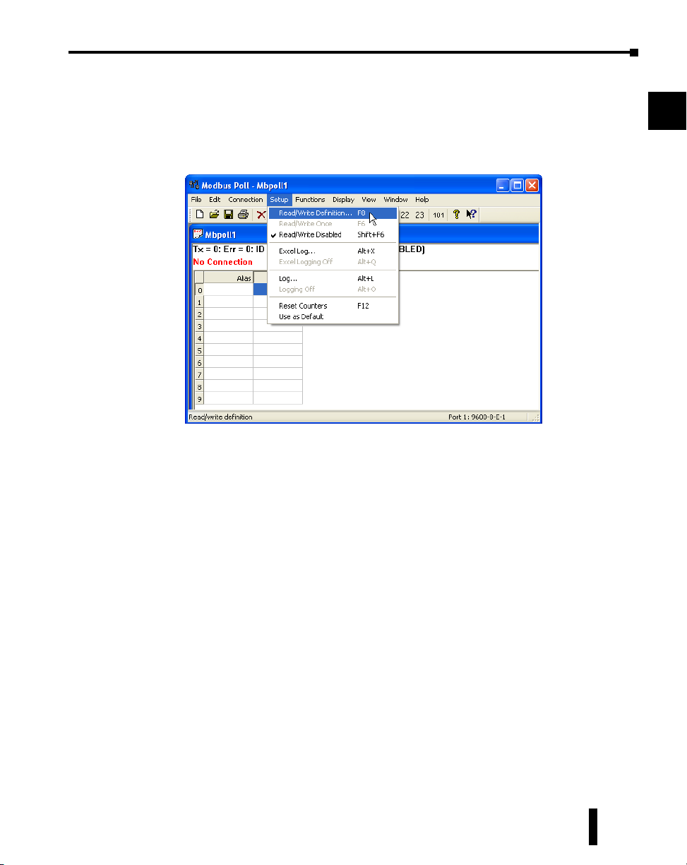
Step 3: Connect to the MB-GATEWAY using the Modbus Poll simulator
software.
Once the software has been obtained from www.modbustools.com and installed according to
the directions provided from their website, open up the Modbus Poll software.
Click on the Setup pulldown menu and select Read/Write Definition as shown:
A
2
3
4
5
6
7
8
9
MB-GATEWAY-USER-M Hardware User Manual, 1st Ed. Rev. H 02/21
10
11
12
13
14
A
B
C
D
A-7
Appendix A: Application Examples
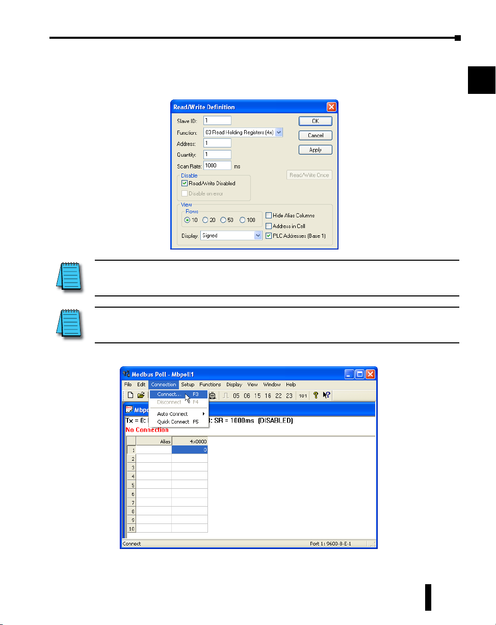
Configure the Read/Write definition for a simple read of the register 400001, which equates
to V0 in the DirectLogic PLCs.
(see http://support.automationdirect.com/docs/Modbus_xref.pdf for more information on
Modbus addressing to DirectLogic PLC addressing equivalents).
Enter in 1 for the Slave ID. This matches the Unit ID in the protocol that will determine which Modbus Serial Slave
will be targeted on the serial side of the MB-GATEWAY. Entering 1 here will match up to the Station Number
configured above in DirectSoft for the DL06 PLC.
A
2
3
4
5
6
7
8
Choosing Function 3 sets up the read for 4xxxxx registers. Checking the “PLC Addresses (Base 1)” in the lower
right corner matches the addressing to the cross reference chart mentioned above. Once this windows has been
configured as shown above, click on OK.
Now click on the Connection pulldown menu and select Connect:
MB-GATEWAY-USER-M Hardware User Manual, 1st Ed. Rev. H 02/21
9
10
11
12
13
14
A
B
C
D
A-8
Appendix A: Application Examples
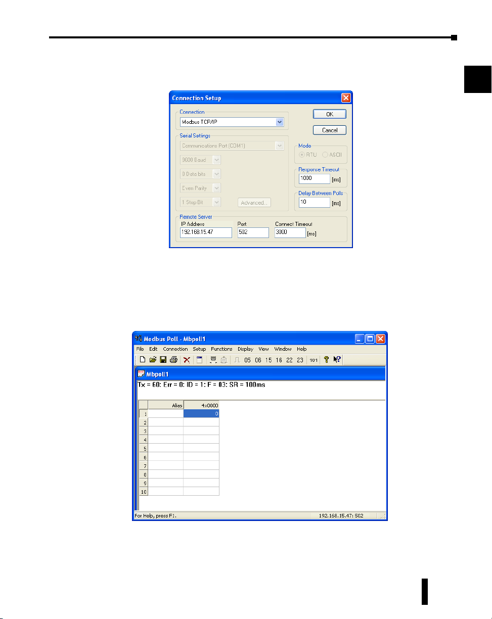
In the Connection Setup window, choose the Modbus TCP/IP connection type. Enter the
IP address of your MB-GATEWAY module in the lower left hand corner. Match everything
else as shown:
Click on OK to connect to the MB-GATEWAY.
If everything has been configured correctly, the counter next to “TX =” will increment rapidly
and the counter next to “Err =” will not increment. If the Error counter is incrementing,
go back and verify that all the steps prior to this one have been followed. If you get an error
that says, “Modbus TCP connection failed”, verify that the IP address of the PC and the IP
address of the GATEWAY are in compatible subnets and can communicate.
A
2
3
4
5
6
7
8
9
10
MB-GATEWAY-USER-M Hardware User Manual, 1st Ed. Rev. H 02/21
11
12
13
14
A
B
C
D
A-9
Appendix A: Application Examples
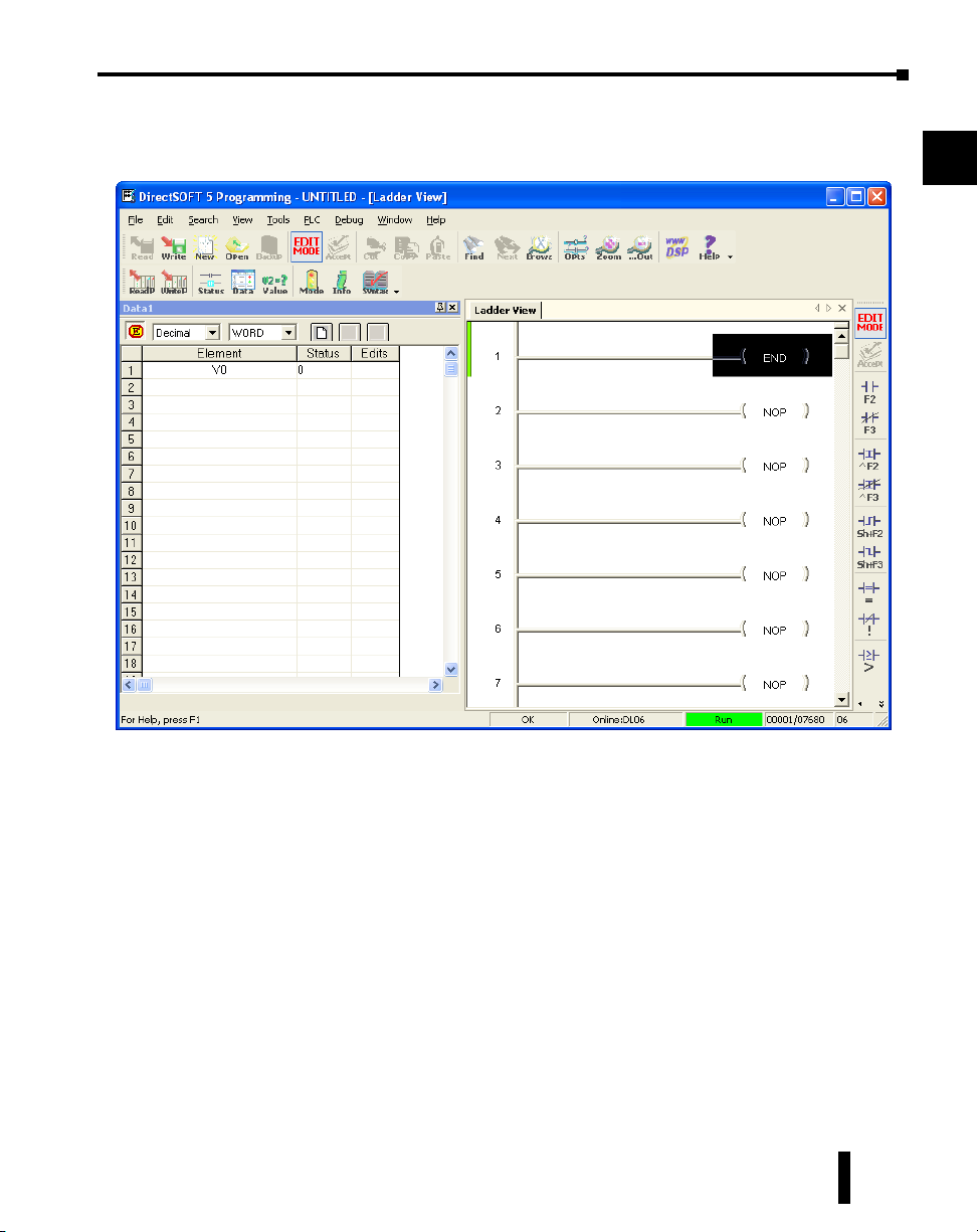
Once Modbus Poll is communicating to the PLC, go into DirectSoft, open up a Data View
window and enter in V0 and change the display type to “Decimal” to match the Modbus Poll
software:
A
2
3
4
5
6
7
8
9
Change the value in data view for V0 to various values and watch the value change in
Modbus Poll to match.
MB-GATEWAY-USER-M Hardware User Manual, 1st Ed. Rev. H 02/21
10
11
12
13
14
A
B
C
D
A-10
Example 2:
RS-485
Appendix A: Application Examples
Using Modbus Poll to MB-GATEWAY with CLICK Slave
This example will illustrate how to use Modbus Poll, which is a PC based Modbus Master
simulator tool, to connect through the MB-GATEWAY to a CLICK PLC via 2 wire RS-485.
Items needed for this example:
• MB-GATEWAY
• CLICK PLC (any C0-01xx-x or C0-02xx-x PLC with 3 pin terminal RS-485 port)
• PC with Modbus Poll installed (free demo is available at www.modbustools.com)
• Small length of Belden 9842 or equivalent cable
• Ethernet switch and cables to connect from the PC to MB-GATEWAY
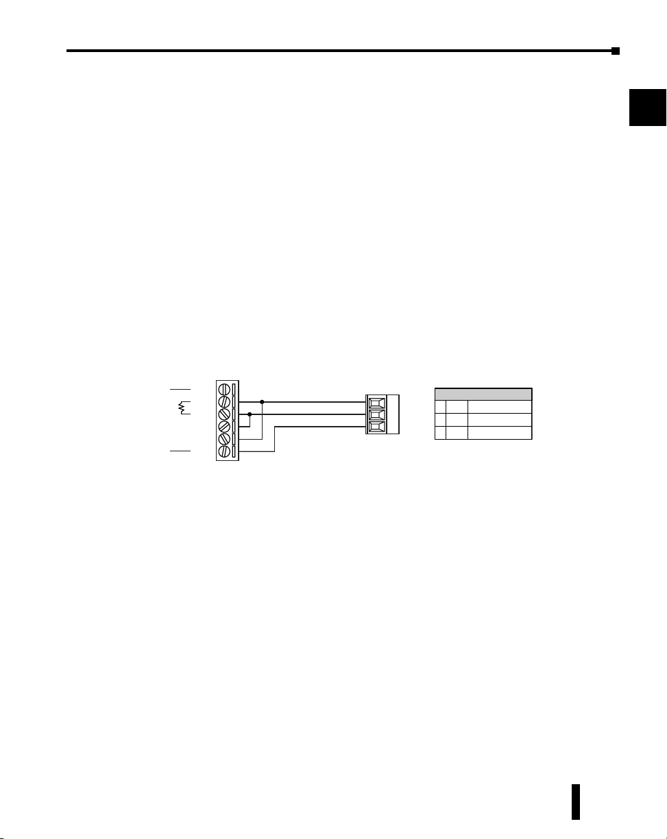
Step 1: Connect the MB-GATEWAY serial port to Port 3 of the CLICK PLC.
Using the short length of Belden 9842, connect the MB-GATEWAY to CLICK’s Port 3 as
shown:
Gateway
GND
RX+
RXTXTX+
Internally Connected
GND
(Gateway contains a
120Ω Termination Resistor
between RX+ and RX-)
Port 3
3 Pin
Terminal Block
+
LG
-
Port 3 Pin Descriptions
+
Signal A (RS-485)
1
(plus)
-
2
Signal B (RS-485)
(minus)
3
Logic Ground (0V)
LG
A
2
3
4
5
6
7
8
9
10
11
MB-GATEWAY-USER-M Hardware User Manual, 1st Ed. Rev. H 02/21
12
13
14
A
B
C
D
A-11
Appendix A: Application Examples
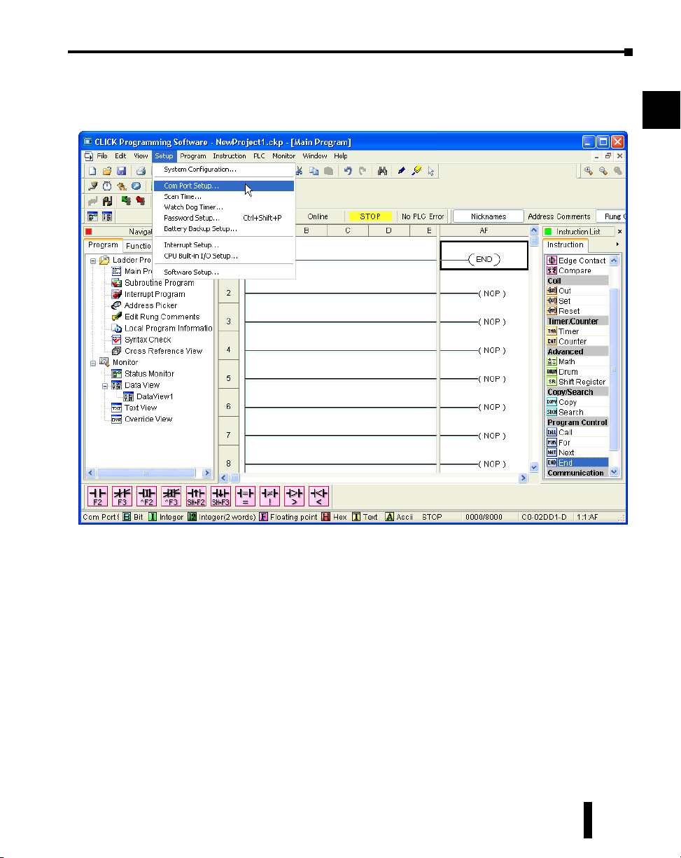
Step 2: Configure the CLICK serial port and MB-GATEWAY serial port.
Connect to the CLICK PLC with CLICK programming software. Go to the Setup pulldown
and select Com Port Setup... as shown:
A
2
3
4
5
6
7
8
9
MB-GATEWAY-USER-M Hardware User Manual, 1st Ed. Rev. H 02/21
10
11
12
13
14
A
B
C
D
A-12
 Loading...