

Page 1
27 December 2011
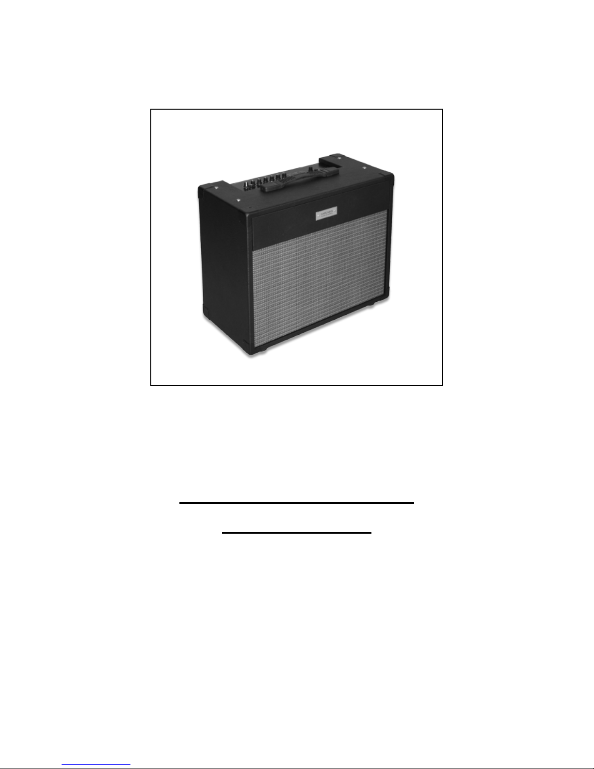
GP4 Guitar Amplifier
User’s Guide
Copyright © 2011 Hardman Guitar Amplifiers Ltd
Page 2
2
GP4 Guitar Amplifier
CAUTION: To reduce the risk of electric shock do not
remove the bottom cover. There are no user
serviceable parts inside. Refer servicing to
qualified personnel.
WARNING: To reduce the risk of fire and electric shock, do
not expose this appliance to rain or moisture.
Take care not that the appliance is not exposed
to dripping or splashing of liquids.
This symbol, wherever it appears alerts you to
the presence of uninsulated dangerous voltage
inside the enclosure - voltage that is sufficient to
constitute a risk of shock.
This symbol, wherever it appears alerts you to
important operating and maintenance
instructions in the accompanying literature.
Please read this manual.
Important Safety Instructions
Detailed Safety Instructions
1) Read, retain, and follow all instructions. Heed all
warnings.
2) Only connect the electric line cord to an earth grounded
AC receptacle in accordance with the voltage and frequency
ratings listed under INPUT POWER on the rear panel of this
product.
3) WARNING: To prevent damage, fire or shock hazard,
do not expose this unit to rain or moisture.
4) Unplug the AC power line cord before cleaning the unit
exterior (use a damp cloth only). Wait until the unit is
completely dry before reconnecting it to power.
5) Maintain at least 6 inches of unobstructed air space
behind the unit to allow for proper ventilation and cooling of
the unit.
6) This product should be located away from heat sources
such as radiators, or other products that produce heat.
7) This product is equipped with a polarized plug (the
central earth pin is offset). This is a safety feature. If you are
unable to insert the plug into the outlet, contact an electrician
to replace your obsolete outlet. Do not defeat the safety
purpose of this plug.
8) Protect the power cord from being walked upon, pinched
or abraded.
9) This product should be serviced by qualified service
personnel when the power supply cord or the plug has been
damaged; or objects have fallen, or liquid has been spilled
onto the product; or the product has been exposed to rain; or
the product does not appear to operate normally or exhibits a
marked change in performance; or the product has been
dropped, or the enclosure damaged.
10) The power supply cord of this product should be
unplugged from the outlet when left unused for a long period
of time, or during electrical storms.
11) Do not drip nor splash liquids, nor place liquid filled
containers on the unit.
12) CAUTION: No user serviceable parts inside, refer
servicing to qualified personnel only.
13) The GP4 Amplifier and loudspeaker system is capable
of producing very high sound pressure levels which may
cause temporary or permanent hearing damage. Use care
when setting and adjusting volume levels during use.
Page 3

3
GP4 Guitar Amplifier
Contents
1. INTRODUCTION
1.0 Introduction 4
1.1 Before getting started 4
1.2 Quick Start Guide 4
2. ROTARY CONTROLS
2.1 Level Controls 6
2.1.1 Tone 6
2.1.2 Input Gain 6
2.1.3 Master Volume 6
2.1.4 Reverb 6
2.2 Tone Controls 6
2.2.1 Bass 6
2.2.2 Mid 6
2.2.3 Treble 6
2.2.4 Presence 6
2.3 PARAMETER CONTROLS
2.3.1 Changing Parameters 7
2.3.2 Frequency 7
2.3.3 Tone/Anti-Fb 7
2.3.4 Amplifier Gain/Volume/Midi Channel 7
2.3.5 Reverb Delay/Depth/Treble/Tape+ reverb 7
2.3.6 Effect Depth/Speed/Delay Level 7
2.3.7 Rhythm Scoop/Gain 7
2.3.8 Comp Threshold/Gain/Slope 7
2.3.9 Wah Level/Speed/Location/Glide direction 8
2.3.10 Gate Threshold/Delay 8
2.3.11 Automatic Parameter Selection 8
3. PUSH BUTTON SWITCHES
3.1 Tap 9
3.2 Rhythm 9
3.3 Gate 9
3.4 Comp 9
3.5 Phase 9
3.6 Wah 10
3.7 Anti-Fb 10
3.8 Reverb 10
3.9 Bright 10
3.10 Effect 10
3.11 Cab 10
3.12 Lock 10
3.12.01 Lock Edit 10
3.13 Tuner 10
3.14 Amplifier (Select) 10
3.15 Reverb (Select) 10
3.16 Effect (Select) 11
3.17 Channel 11
3.18 Channel Copy 11
4. Restoring Factory Settings 11
5. Audio Line Output 12
6. Footswitch control 12
7. Getting a good Distortion Tone 13
8.0 Midi Interface 14
8.1 Introduction 14
8.2 Midi Messages 14
8.3 Setting the Midi Channel 14
8.4 Midi Message Codes 15
9. Summary of Parameter Control Functions 16
10. Specification 17
11. GP4 Signal Path 18
Foreword
Dear Customer
Welcome to the GP4 Guitar Amplifier group of users. GP4
is the result of extensive research and design, bringing
together modern innovative technology with the traditional
needs of the guitarist.
The GP4 has been design to give immediate access to the
standard functions expected from a guitar amplifier with an
intuitive front panel. However the GP4 is extremely versatile
and has many features beyond that of most amplifiers that
enable it to deal with a wide range of guitars, playing styles
and performance locations.
Please read this manual, it will help you explore and use the
full capabilities of your amplifier. Finally and importantly
please be aware of all the safety instructions.
Page 4

4
GP4 Guitar Amplifier
1.0 Introduction
The GP4 guitar amplifier has been designed to provide
sound re-enforcement and expression for a wide range of
guitars and playing styles.
It is compact, powerful, versatile, light weight, enhancing
the playing of both enthusiast and professional guitarist.
To cope with such a wide combination of available settings
the GP4 automatically stores to one of six channel
configurations. Even the rotary controls (except Input Gain
and Master Volume) can have their positions stored and
recalled.
The amplifier comes integrated with a number of popular
effects and has audio outputs for amplifiers, mixers or
speakers.
There is an extensive remote control facility via a Midi
interface. With an optional footswitch providing a more basic
alternative.
1.1 Before getting started
Your GP4 Amplifier has been carefully packed for transport.
If the cardboard packaging shows any signs of damage the
amplifier should be carefully inspected.
Please immediately inform the transport company from
which you took delivery, or claims for replacement or repair
may be rendered invalid.
Please ensure that the original packaging is used to return
an amplifier.
Please ensure that children cannot play with the amplifier or
the packaging.
Please dispose of the packaging in an environ-mentally
friendly way.
Please ensure that the GP4 amplifier has adequate
ventilation, to the top and back. Do not cover or place near
radiators
1.2 Quick Start Guide
The first time you switch on your GP4 amplifier it will turn ON
all the LEDs and then revert to the clean Jazz amplifier setting,
No Reverb, No Effect and Channel 1 selected. Turn the Volume
and Input Gain control to minimum. Set the other controls to
central positions. Plug in your guitar and set the Input Gain
Control so that the Led above it flashes at a reduced brilliance
compared with the other Leds when playing at any level. If the
Input Gain is set too high the Led will flash at full brilliance, this
should be avoided. Turn up the Volume as required.
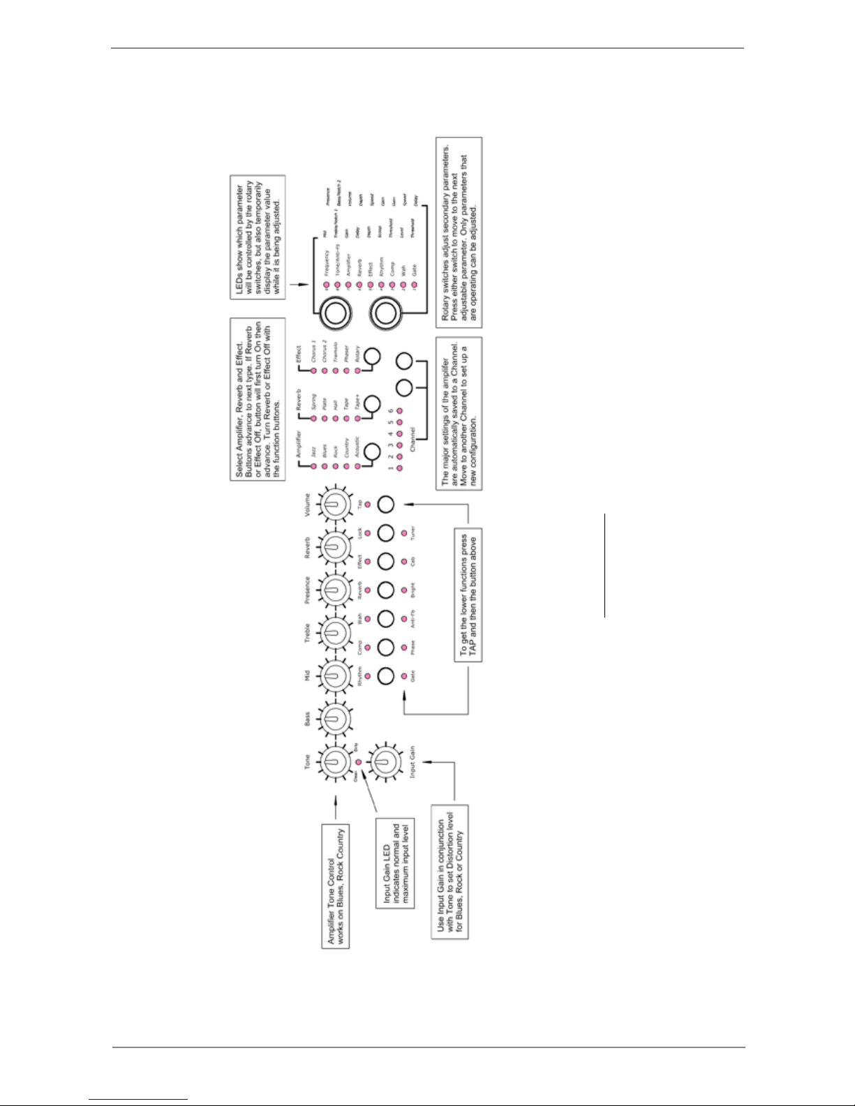
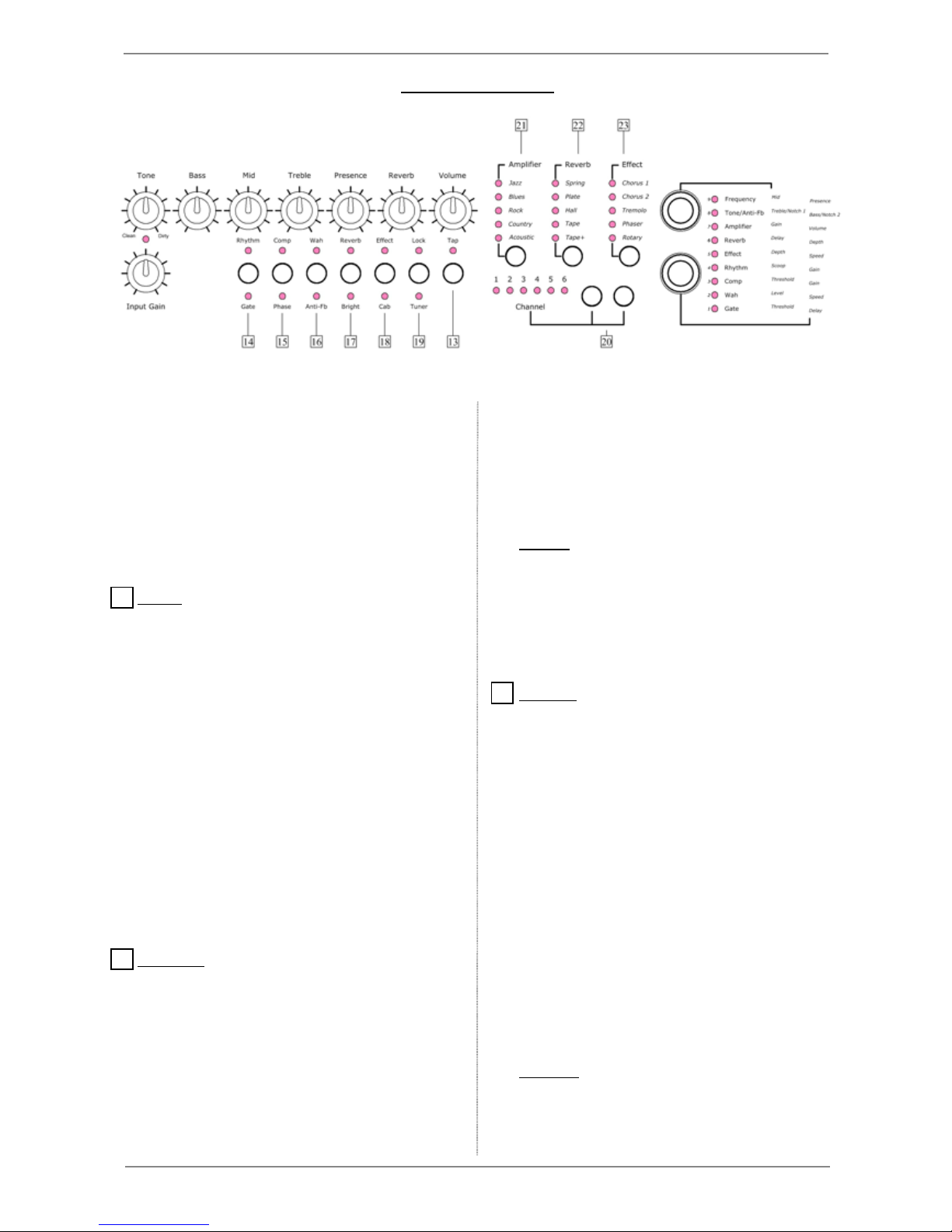
Now have a look at Figure 1.0. for a short summary of the GP4
front panel functions.
Page 5
5
GP4 Guitar Amplifier
Figure 1.0
Quick Start Guide
Page 6
6
GP4 Guitar Amplifier
2.1 Level Controls
2.1.1 Tone
Sets the amount of distortion in the Blues, Rock and
Country settings. When the Jazz and Acoustic amplifier
operating modes are selected this control has no effect.
Initially start with the control in a central position, then
set the Input Gain just to the point of distortion . The
control will then provide a range of tone from clean
through to heavy saturation with an approximately
constant volume.
However there is no hard and fast rule determining
how the Tone and Input Gain controls should be used in
relation to one another and it is an area where the user
can explore a wide range of possible tones.
2.1.2 Input Gain
Sets the amplifier operating level. Allows for the
differing pickup sensitivities from guitar to guitar. The
Input Gain should be set so that the Clip LED (9)
occasionally comes On at half brightness, but never at
full brilliance.
The Input Gain control is used in conjunction with the
Drive control to set the amount and quality of distortion
in the Blues, Rock and Country settings.
2.1.3 Master Volume
Sets the overall level from the loudspeaker power
amplifier. (Internal speaker or external speaker output.)
This control has no effect on the line outputs.
2.1.4 Reverb
Controls the level from the Reverb-Delay effects unit.
2.2 Tone Controls
2.2.1 Bass
Controls the level of low frequencies
2.2.2 Mid
Controls the level of mid frequencies. The frequency
at which the control operates can be changed over a
wide range with the Parameter - Frequency - Mid, see
2.3.2.
2.2.3 Treble
Controls the level of high frequencies
2.2.4 Presence
Provides a bell shape boost or cut. The frequency at
which the control operates can be set over a wide range,
100 - 4000 Hz, set using the Parameter - Frequency Presence, see 2.3.2.
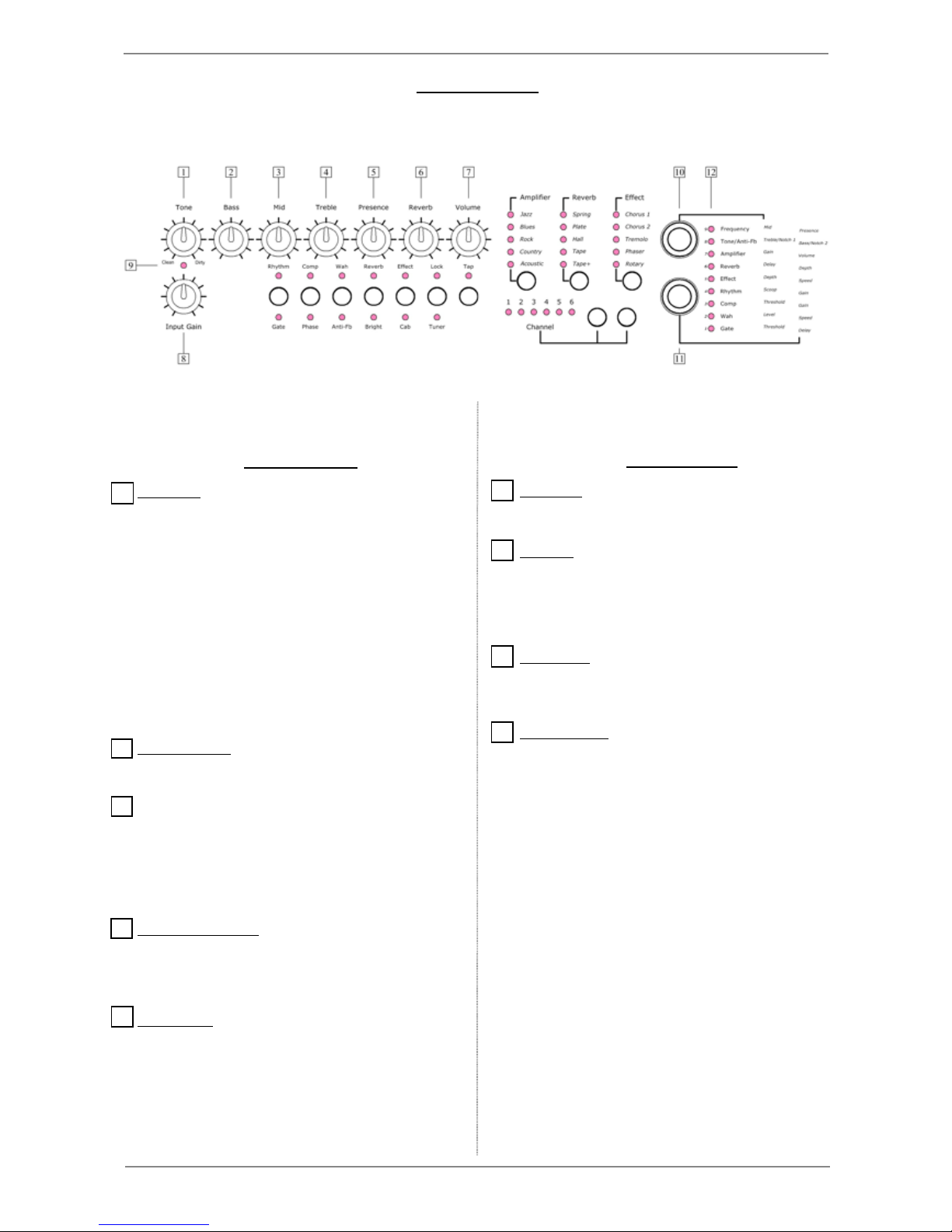
2.0 Rotary Controls
Fig 2.0 GP4 Front Panel Rotary Controls
1
8
7
6
2
3
4
5
9
Page 7

7
GP4 Guitar Amplifier
2.3.1 Changing Parameters
The Parameter Control knobs are pushed momentarily to
move to select the Parameter to be controlled. The upper
Parameter Control moves
up
to the next selected parameter
and similarly the lower Parameter Control moves
down
.
A parameter cannot be adjusted unless its associated effect
is On. For example, the Reverb must be On before the Delay
and Depth can be adjusted. If an effect is turned Off while its
parameter is selected then the displayed parameter will revert
to the Tone/Anti-Fb.
When a parameter is altered the approximate value is
briefly displayed using the Parameter LEDs. The Parameter
LEDs revert to normal operation after a couple of seconds.
The Amplifier, Reverb, Effect, Comp and Wah functions
have more than two parameters. The additional parameters
are accessed by holding the TAP button down at the same
time as turning the parameter control.
2.3.2 Frequency
These parameter controls set the operating frequency of
two of the tone controls, the Mid and Presence, provided the
Lock is not in operation. The frequencies set are stored along
with the Channel. This means that each Channel has its own
Mid and Presence Frequency settings, but these are shared
by all the possible Amplifier types for that Channel.
2.3.3 Tone/Anti-Fb
This parameter control has two functions. When Anti-Fb is
not in operation the parameter controls adjust filters used to
shape the overall low and high frequency response of the
amplifier. One use would be to allow for variations from one
guitar to another. To help with this the filter settings can be
different for each channel allowing channels to be set for
different guitars. Both the Bass and the Treble filters come
before distortion generation. When Anti-Fb is in operation the
two parameter controls are used to set notch filters that can
be useful for suppressing feedback from electro-acoustic
instruments. When a notch filter is set this remains
independent of the channel.
11
12
2.3 Parameter Controls
These provide a simple means of controlling the large
number of parameters that are associated with the
various effects. These two rotary controls are of the
digital type, having a click action, continuous rotation and
a combined push switch.
The Parameter LEDs have a number of functions. The
primary functions is to show the current Parameter that
the Parameter Controls are going to modify.
2.3.4 Amplifier Gain/Volume
Sets the levels before and after the distortion generation. In
the case of the clean Jazz and Acoustic amplifiers the two
controls operate in series, both having the same effect. These
two controls provide a unique Gain and Volume for each of the
Amplifiers and for each Channel. It provides a powerful way of
coping with different guitar sensitivities and presetting the
output level.
Holding down TAP, and the upper parameter control will
display the Midi Channel but not change it. The lower control will
change the Midi Channel. See 6.0 Midi Interface.
2.3.5 Reverb Delay/Depth/Treble/Tape+ reverb
For Spring, Plate and Hall, the Delay control sets a short time
delay that precedes the principle reverberation effect for which
the Depth controls sets the length and density. For Tape and
Delay, the Delay control sets the time delay and the Depth
controls sets the feedback from the output of the delay back to
its input.
Holding down TAP and moving the lower parameter control
changes the treble response of the reverb. Holding down TAP
and moving the upper parameter control changes the reverb
that will be used in Tape+ and also provides access to a purely
Digital Delay. The result is shown on the top four Parameter
LEDs -
9 - Spring
8 - Plate
7 - Hall
6 - Digital Delay
2.3.6 Effect Depth/Speed/Chorus Delay Gain
Controls the Depth and Speed of the modulation used for
each of the Effects. The Chorus Effects consist of mixing a time
varying delayed signal with the original. The level of this signal
can be altered with the Lower Parameter Rotary while holding
down the TAP button. This allows subtle Chorus Effects to be
set.
2.3.7 Rhythm Scoop/Gain
Scoop adjusts the level of the frequency selective scoop filter,
0-10 dB. Gain sets the overall cut in level from 0-15 dB.
2.3.8 Comp Threshold/Gain/Slope
The Threshold and Gain set the signal level at which
compression starts and the output level from the Compressor.
When the Guitar signal is greater than the Compressor
Threshold signal compression starts and is indicated by the
Compressor status Led dimming. The Compressor slope can be
selected by holding down the TAP button and turning the lower
rotary. The selected slope is shown on the top three parameter
LEDs. The top most indicates infinite slope, the next two down
indicate 4:1 and 2:1.
10
Page 8

8
GP4 Guitar Amplifier
2.3.9 Wah Level/Speed/Location/Glide direction
When the Wah effect is turned On from the front panel it is
in Auto Mode. That is the effect is controlled from the guitar
signal level. The Level sets the threshold at which the Wah
effect begins to operate. Turn the Level parameter control
clockwise to increase the sensitivity to signal level. Speed
sets how fast the Wah effect responds to changes in signal
level. Turn the Speed parameter clockwise to make the Wah
effect follow more closely changes in playing level.
Holding down TAP and changing the upper parameter
allows the selection of whether the Wah filter location is to be
before or after the distortion Tone generation. Clockwise
selects pre distortion and displays ‘9’ on the parameter LEDs.
Anti-clockwise selects post distortion and shows ‘5’. Similarly
TAP plus the lower rotary selects the Auto-Wah filter glide
direction. Clockwise rotation selects glide up and shows ‘9’ on
the parameter LEDs, anti-clockwise selects glide down and
shows ‘5’.
2.3.10 Gate Threshold/Delay
Threshold sets the signal level at which the Gate operates.
When the signal level drops below the threshold the Gate
blocks the signal after a short delay that can be set using the
Delay parameter. The Delay parameter controls how rapidly
the gate closes and can be used to match the Gate
characteristic to your playing style. Short delays give a very
abrupt ending which when used with a high threshold can
provide an interesting effect in itself.
2.3.11 Automatic Parameter Selection
This is a facility that can be turned ON and OFF using
TAP+Parameter UP or TAP+Parameter Down. When ON, the
selection of Reverb, Effect, Wah, Comp, Rhythm, Gate,
AntiFb, will automatically cause the associated parameter to
be selected.
Page 9
9
GP4 Guitar Amplifier
3. Push Button Switches
3.1 Tap
This button has two functions -
1. To access the lower functions of the six buttons to
the left. To do this press the TAP button and then within
one second the button for the required function. Pressing
a second button within the one second time period also
cancels the TAP one second time period. For example
pressing the TAP button twice will cancel its effect.
2. To control the speed of certain effects parameters
by tapping the TAP button at the required speed.
The parameters that can be controlled are -
1. Tape repeat time
2. Tremolo or Rotary speed
When a parameter can be set using the Tap button
the LED above will be illuminated. To select a parameter
for Tapping, the effect must be ON, and the parameter
selected using the Push switches in the Parameter rotary
controls.
3.2 Rhythm
When ON, the volume is reduced and the mid
frequencies reduced by amounts that can be adjusted by
the Parameter controls (see section 2.3.5)
The effect consists of two parts -
1. A frequency selective scoop filter
providing 0-10dB cut at 600Hz
2. A gain control with a 15dB range.
The filter and gain control operate in front of any
distortion generation. When Rhythm is ON it has its own
settings for the ON-OFF status of Compressor, Wah,
Reverb, and Effect. The way these are set when Rhythm
is ON, will stay with it. When Rhythm is turned OFF, the
original settings for Compressor, Wah, Reverb, and
Effect will be restored.
3.3 Gate
Turns ON/OFF a signal gating system. This
comprises a signal level dependent switch that blocks
the input when it has fallen to a low level. The aim is to
remove noise signals that could be of annoyance when
the wanted guitar signal is not sufficient. The Gate
function has two Parameters, Threshold and Delay,
(see 2.3.20 )
3.4 Comp
Turns the Compressor ON/OFF.
This comes before the distortion section. The
compressor slope is accurately controlled to 2:1, 4:1 or
infinite slope. (See 2.3.8 ) For a 2:1 slope a 2 dB change
at the input above the compressor Threshold gives 1 dB
change at the output. Similarly 4:1 gives 1 dB change in
output for 4 dB change at the input. Infinite slope means
that the output remains essentially constant for inputs
above the Threshold. The 2:1 slope is effective in
controlling instrument dynamics while maintaining
expressiveness.
The Compressor effect is controlled by setting the
level above which compression begins and the output
level. These are set by the parameters Comp Threshold/Gain. ( see 2.3.8 )
The compressor action is only operative above a
fixed input level Threshold. When this Threshold is
exceeded the Comp LED will brighten, indicating that the
signal is now being compressed.
3.5 Phase
Reverses the Phase of the Output in relation to the
input. This is primarily for use when the Amplifier is in
Fig 3.0 GP4 Front Panel Push Button Switches
The six buttons on the left (14-19) each control two
functions as indicated by the status of the LEDs above and
below the button. Normally pressing any of these will operate
the function that is indicated by the LED above the button.
To operate the function below the button first press the TAP
button and then the required function button within one
second. Once a time period of one second has passed the
buttons will revert to controlling the upper functions.
13
14
15
Page 10
10
GP4 Guitar Amplifier
Acoustic Mode to get the best working conditions where
an electro -acoustic guitar is the signal source.
3.6 Wah
Turns Auto Wah ON/OFF. This has four Parameter
controls, Level, Depth, Location and Glide Direction (see
2.3.9). The operation is triggered from the guitar signal
level. For the effect to operate correctly Level must be
adjusted for the desired effect.
3.7 Anti-Fb
When ON Anti-Feedback places in the signal path
two notch filters that can be used to reduce the possibility
of acoustic feedback. These notch filters can be swept
over a wide range. The frequency at which they operate
can be set from the Parameter controls Notch 1 and
Notch 2 (see 2.3.3).
3.8 Reverb
Turns Reverb ON/OFF. See Reverb 3.15
3.9 Bright
Bright applies a boost to upper mid frequencies.
3.10 Effect
Turns Effect ON/OFF. See Effect 3.16
3.11 Cab
Applies to the Line Output frequency response
shaping that rolls off the extreme bass and treble
simulating the natural response of a guitar amplifier
cabinet and loudspeaker drive unit.
3.12 Lock
The Lock button controls a memory system for storing
and recalling the positions of the Drive, Bass, Mid,
Treble, Presence and Reverb rotary controls for each
Channel. To store the locations of these controls, press
the Lock button and hold it down until the Lock LED
flashes. To recall stored locations press the Lock button
in the normal way (briefly). The Lock LED will be
illuminated. The Drive, Bass, Mid, Treble, Presence and
Reverb rotary controls will no longer have any effect, but
their position relative to the stored value is temporarily
displayed on the Channel LEDs. When the control is in
the same position as the stored location the central four
Channel LEDs will be illuminated. This pattern of LEDs
will move left or right as the control is moved either side
of the stored value.
3.12.01 Lock Edit
If it is required to adjust the position of an individual
Locked control this can be done by enabling the Lock
Edit mode. The Lock Edit mode can only be entered
when Lock is ON. With Lock ON, hold down the TAP
button then press and release the Lock button. The Lock
Led will commence flashing, indicating that the Lock Edit
mode is in operation. Moving any of the rotary controls
while the Lock LED is flashing will over ride the stored
value. Frequency Parameters for Mid and Presence can
also be adjusted (see 2.3.2). Press the Lock button again
when all the changes are made, the new values will be
stored and the Lock condition will be resumed.
3.13 Tuner
Turns on the built-in guitar tuner. All normal LED
display functions are suspended. Pressing any button
other than TAP will return the amplifier to normal
operation. As each string is played the string number is
displayed using the top six parameter LEDs. The top
most LED corresponding with top E. The deviation from
correct tuning is displayed using the Channel LEDs.
Correct tuning is indicated by all six LEDs being
illuminated. This pattern moves left and right as the
string pitch is below or above the correct pitch. The end
LEDs remain permanently illuminated. To get the fastest
and most consistent response to the string pitch it is
helpful to make sure that the five strings not being tuned
are damped.
The factory preset value for A is 440 Hz, but this can
be changed from 440 to 448 Hz. To do so, engage the
Tuner operation. Hold down the TAP button, the value
for A will be shown on the Parameter LEDs, top to
bottom indicates 440 to 448 Hz (9-1). The value for A
can be altered using the lower rotary.
The Tuner function also provides a convenient way
of quickly Muting all the audio outputs.
3.14 Amplifier (Select)
Selects the style of Amplification. The Jazz and
Acoustic settings are clean. The Acoustic frequency
response is overall flat and includes frequency
compensation for the drive unit to give the best response
for an electro-acoustic instrument.
The Country, Blues and Rock settings have the
option, using the Drive control, to add varying levels of
distortion. Jazz, Blues and Rock have a similar
frequency response providing a bright punchy tone. The
Country setting has mid frequency scoop and lighter
distortion to provide a clear, singing tone.
Where a jazz guitarist would like slight distortion, to
add colour and limit the dynamic range, the Country,
Blues and Rock settings can be used with the drive
control kept toward its minimum.
3.15 Reverb (Select Type)
Selects the type of Reverb or Delay. When the
Reverb is OFF there are no LEDs illuminated. If the
Reverb is OFF pressing the Reverb button will turn the
Reverb ON without changing the selected Reverb type.
When the Reverb is ON pressing the Reverb button will
select the next reverb type.
Spring, Plate and Hall provide a short delay followed
by high quality stereo reverberation system with the two
outputs going to the internal power amplifier and line
output. The delay and reverb time can be set from the
Parameter controls (see 2.3.3).
The Spring setting provides a good general purpose
reverb similar to a traditional mechanical unit. The range
16
17
19
22
21
18
Page 11

11
GP4 Guitar Amplifier
23
20
of variation of delay and reverb is limited in keeping of
what can be expected from such units.
Plate provides a bright medium delay, while the Hall
setting is expansive and diffuse with the options for
setting long reverb times.
Tape provides a straight delay with feedback for
providing decaying repeats. The Tape setting simulates
the softer response associated with a mechanical tape
loop echo unit. The time delay and repeat level can be
set by the Parameter Controls (see 2.3.3).
Tape+ provides the combination of Delay and Reverb
or a purely Digital Delay. Delay and feedback are set in
the same way as Tape. The Reverb type can be selected
from one of three possibilities by selecting the the
Reverb Parameter (see figure 2.0 [10][11] ) holding down
the TAP button and turning the lower Parameter Control
[11]. The selected Reverb Type is displayed momentarily
on the top three parameter LEDs corresponding to
Spring(9), Plate(8), Hall(7) from the top downwards.
Tape+ also provides the option of a purely digital
delay. This can be selected as above by holding down
the TAP button and turning the lower Parameter Control
[11] and selecting parameter (7).
The Reverb path has its own tone control that can be
accessed from the Parameter Controls. To adjust the
Reverb treble, the Reverb must be On, select the Reverb
parameter, press and hold down the TAP button, while
using the lower rotary control to adjust the Reverb treble
level. The Reverb tone is set independently for each
Channel, but all the Reverb types within one Channel
setting will share the same tone.
3.16 Effect (Select)
Selects the Effect type. When the Effect is OFF there
are no LEDs illuminated. If the Effect is OFF pressing the
Effect button will turn the Effect ON without changing the
selected Effect type. When the Effect is ON pressing the
Effect button will move to the next option.
There are four different effects, Chorus 1 and 2,
provide a light and full chorus. Tremolo is a traditional
amplitude modulation. Phaser gives a rich time delay
derived phasing effect, while Rotary gives a pleasing
frequency modulation inspired from mechanical rotating
loudspeaker systems. All of the effects can have there
depth and speed set from the Parameter controls. In
addition the TAP button can be used to set the speed of
the Rotary and Tremolo.
3.17 Channel
The channel switching system is a way in which the
user can quickly switch the amplifier from one
configuration to another. The system is simple, all of the
current amplifier conditions are stored automatically to
the displayed channel, except for the Volume and Input
Gain. If the Drive, Bass, Mid, Treble, Presence, Reverb
are to be stored along with the channel then the Lock
must be On. Pressing the Channel buttons cycle left or
right through the available channels.
4. Restoring Factory Settings
To restore all the settings that your amplifier came with,
switch On the amplifier while holding down the TAP button.
The LED above the the TAP button will flash three times, if
the TAP button is still being held down after the third flash the
factory settings will be restored, releasing the button before
will cancel the restore operation.
3.18 Channel Copy
The entire settings of one Channel can be copied to its
neighbour, up or down. This is done by holding down TAP
while pressing Left or Right Channel. The LED for the
Channel that is to be the destination of the copy will start to
flash. Holding down TAP and pressing the same Channel
button again will confirm the copy, with both Channel LEDs
flashing a couple of times. Pressing a Channel button without
TAP will cancel the Copy operation and cause a normal
Channel change.
Page 12
12
GP4 Guitar Amplifier
5. Audio Line Output
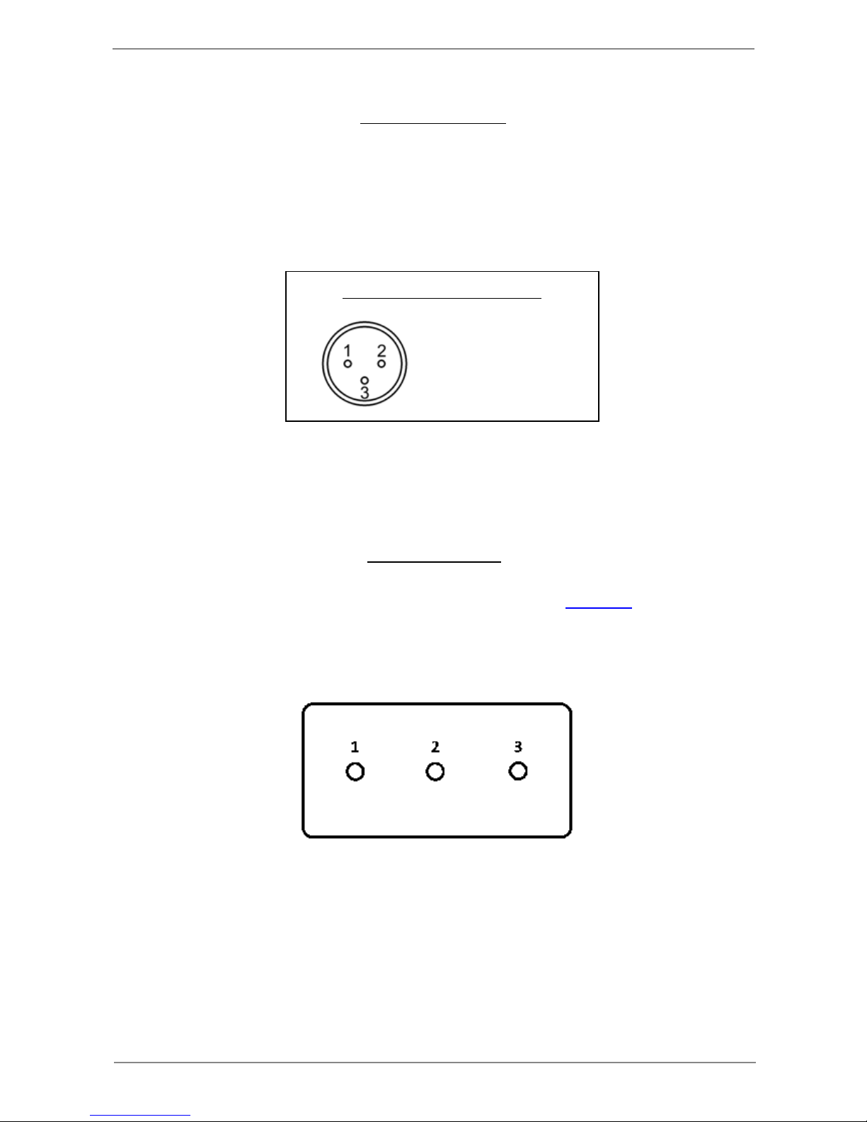
1 - Ground.
2 - Signal High
3 - Signal Low
XLR Line Out Signal Connections
Low level audio output is available from either ¼" jack or XLR socket. The XLR output is suitable for feeding
a balanced line by using signal connections to pins 2 and 3. If an un-balanced output is required from the
XLR socket then the signal should be taken from pins 2 and 1. There is no audio signal on pin 3, but this
terminal provides an impedance to ground that matches the impedance of the Signal High output. This helps
minimise common mode interference.
6. Footswitch Input
A optional footswitch input is available on the back panel. This uses a standard 1/4” jack stereo jack socket.
The control input is compatible with the Switch-3™, 3 button footswitch, from TC-Helicon™. The buttons provide control of Channel selection, Rhythm and Tuner, the latter can also act as an amplifier mute.
Button 1 Select next Channel down- wrapping round from 1
to 6
Button 2 Select next Channel up- wrapping round from 6 to 1
Button 3 Rhythm On - Off
Button 3 - hold down for 1 second Tuner ON (output mute) -press any button to return
to normal operation
Page 13

13
GP4 Guitar Amplifier
7. Getting a good Distortion Tone
For those who want to get down to the nitty-gritty you can
skip the next couple of paragraphs in which I provide an
overview of the object of applying distortion to the guitar.
The Electric Guitar and Distortion - brief overview
The Electric Guitar is characterised by long thin steel
strings attached to an almost completely non-resonant body,
with a transducer system that has minimal effect on the string
vibration and is used to provide an electrical facsimile of the
string vibration. Such a system when played through a high
performance low distortion amplifier produces a delicate
sound with a large initial transient and considerable high
harmonics. Plucking a string more heavily tends to produce
more volume but with little change in harmonic structure. It
has much in common with the Harpsichord, also a plucked
instrument with thin steel strings, and like the Harpsichord
struggles when used up against other instruments. The
Harpsichord was superceded by the Piano which among
other things is characterised by having thick strings under
high tension on a heavy frame. This type of development is
not available to the electric guitar. It must remain within the
capabilities of the human hand for its operation, where if
anything the demands of modern playing have meant that
strings have got thinner.
The inspiration for the modern electric guitar tone is more
in line with the characteristic of the Saxophone. Here we have
an instrument with considerable power in the lower
harmonics and very little in the way of initial transient. In
addition when blown heavily the Saxophone is capable of
considerable thickening of the middle harmonics due to
distortion added by non linear movement of the reed. The
electric guitar does not naturally produce a noticeable
thickening of harmonics when plucked with more force, but
there are two ways of achieving this, by saturation or clipping
of the signal in the Pickup or in the Amplifier. This process
also has the desirable effect of reducing the initial transient.
Amplifier clipping initially came about because of normal
short comings rather than intentional design, but was
eventually recognised as an integral and desirable
characteristic of an amplifier intended for guitar amplification.
GP4 and Distortion Generation
The aim of GP4s Distortion is to reduce but not eliminate
the initial transient, to thicken the lower harmonics and
increase the sustain. By carefully controlling the onset of
distortion new capabilities of expressiveness become
possible. Unlike traditional amplifiers the distortion is
available at all operating levels. Due to the peculiarities of
human hearing our ability to hear extreme bass and treble
frequencies at low listening levels is less than at high levels.
Thus an amplifier set up for moderate room levels will be
perceived as having too much treble and bass when operated
at higher levels for a larger environment. This means that the
treble, mid and bass controls cannot be used to control the
distortion and are placed after distortion generation. The
guitar source signal has considerable effect on the distortion
tone. In general we want moderate upper middle harmonics
and not too much bass. This means that it is necessary to
have control of the bass and treble response in front of the
distortion generation to cope with the wide range of signals
from humbucker to single coil pickups from bridge position to
neck position.
The following controls operate in front of the distortion
generation :-
1. Tone/Treble and Tone/Bass ( see 2.3.3 )
These two filters are extremely useful. They both have a
shelving shape. This means that after applying a mild cut the
response flattens out leaving more of the extreme treble and
bass than if traditional bass and treble tone controls were
used.
2. Presence Control ( see 2.2.4 )
This control offers considerable opportunities for
experimentation. Unlike its operation in a traditional amplifier
that would be at a single fixed frequency, the GP4 Presence
Control can operate over a wide range of frequencies from
100 Hz up to 4 KHz.
3. Compressor ( see 3.4 )
The high performance GP4 compressor can be used to
control the depth of distortion. Set a 2:1 compression with a
Threshold at or just above the point at which distortion
commences and then adjust the Gain for the overall level of
distortion. The general characteristic of compression in front
of distortion is to give a very fluid sound with a singing quality,
together with a reduction in inter-modulation distortion that
makes more sense of chords.
Page 14

14
GP4 Guitar Amplifier
8.1 Introduction
The GP4 Amplifier has Midi Input and Thru Sockets. The
Thru socket passes out all the data that appears at the Input
socket. The Midi input allows the remote control of the main
amplifier functions, together with real time control of the Wah
frequency and overall volume. The Midi control codes for
these are compatible with those produced by the Behringer
FCB1010, using factory presets for the V-AMP family
products. With this setting the left expression pedal will
control Wah frequency and the right will control the volume.
8.2 Midi Messages
The table shows all the midi messages that GP4 will
respond to. X indicates a value that is not used. All of the
commands behave in a similar way to the front panel controls
with the exception of Wah ON. This disables the Auto Mode
and instead the Wah frequency can be controlled by a foot
pedal that supplies Wah Frequency Control values. Note that
if the overall volume is changed using the Midi Controller and
the controller is removed or the Midi disabled or the Midi
address changed the volume will remain as set. The normal
volume can be restored without the aid of a Midi Controller by
switching the GP4 Off and back On.
8.3 Setting the Midi Channel
The Midi control can be disabled or set to respond to
commands on Midi channels 1 - 9. This is done by the use of
the Parameter controls and the TAP button. Press the
Parameter controls to select the Amplifier Parameters. To
display the Midi Channel without changing it, hold down the
TAP button and turn the Upper Parameter Control. If all the
Parameter LEDs are extinguished this indicates that Midi is
OFF. If Midi is ON then the Parameter LEDs will indicate the
channel in the range 1-9. To change the Midi channel or turn
Midi OFF, hold down the TAP button and use the lower
parameter control. After the parameter LEDs have displayed
the Midi state they will revert back to normal operation after a
couple of seconds.
8. Midi Interface
Page 15

15
GP4 Guitar Amplifier
Command Byte 1 Byte 2 Byte 3
Volume Control 7 0 - 127
Wah Frequency Control 27 0 - 127
Select Channnel 1 Program Change 0 X - don’t care
Select Channnel 2 Program Change 1 X
Select Channnel 3 Program Change 2 X
Select Channnel 4 Program Change 3 X
Select Channnel 5 Program Change 4 X
Select Channnel 6 Program Change 5 X
Rhythm ON Program Change 10 X
Compressor ON Program Change 11 X
Reverb ON Program Change 12 X
Effect ON Program Change 13 X
Lock ON Program Change 14 X
Rhythm OFF Program Change 15 X
Compressor OFF Program Change 16 X
Reverb OFF Program Change 17 X
Effect OFF Program Change 18 X
Lock OFF Program Change 19 X
Jazz Amplifier
Program Change
20
X
Blues Amplifier
Program Change
21
X
Rock Amplifier
Program Change
22
X
Country Amplifier
Program Change
23
X
Acoustic Amplifier
Program Change
24
X
Spring Reverb ON
Program Change
30
X
Plate Reverb ON
Program Change
31
X
Hall Reverb ON
Program Change
32
X
Tape Reverb ON
Program Change
33
X
Tape+ Current Preset Reverb ON
Program Change
34
X
Tape+ Spring Reverb ON
Program Change
35
X
Tape+ Plate Reverb ON
Program Change
36
X
Tape+ Hall Reverb ON
Program Change
37
X
Reverb OFF
Program Change
39
X
Chorus 1 Effect ON
Program Change
40
X
Chorus 2 Effect ON
Program Change
41
X
Tremolo Effect ON
Program Change
42
X
Phaser Effect ON
Program Change
43
X
Rotary Effect ON
Program Change
44
X
Effect OFF
Program Change
49
X
8.4 Midi Message Codes
Page 16
16
GP4 Guitar Amplifier
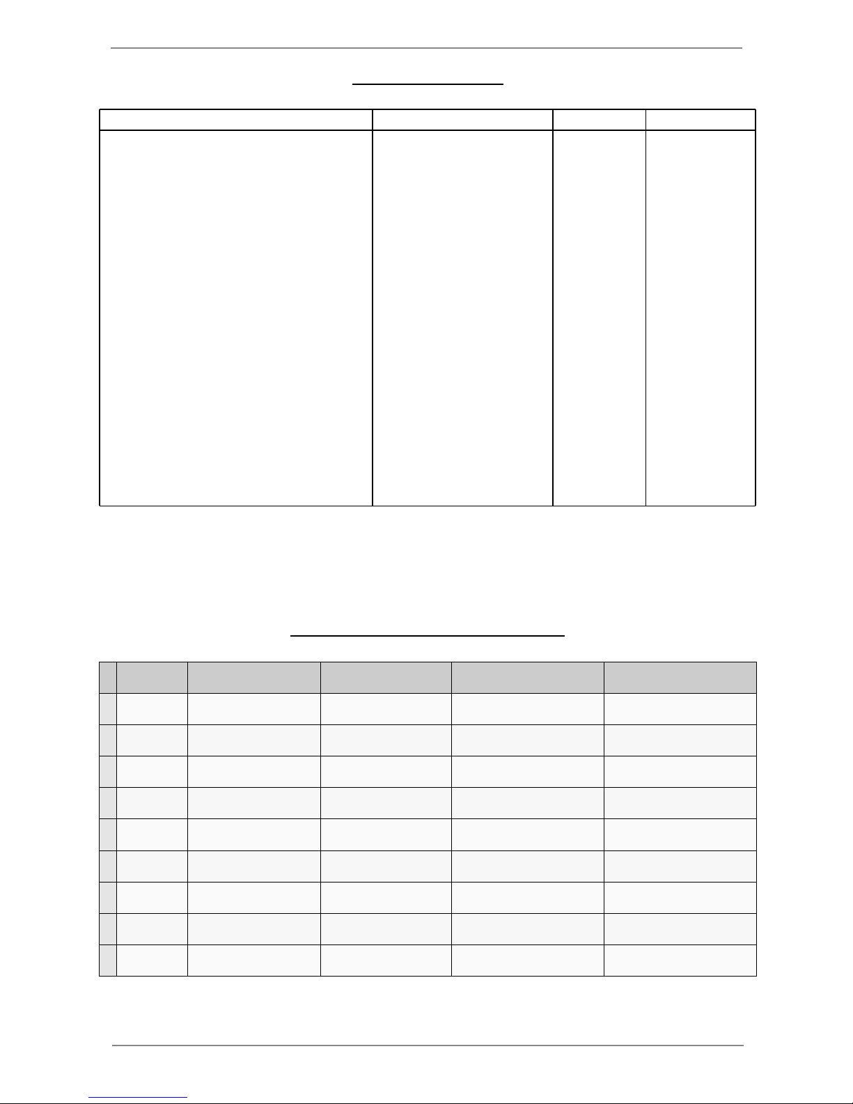
Parameter Upper Control Parameter Lower Control Parameter TAP+Upper Control Parameter TAP+Lower Control Parameter
9
Frequency Mid Control Presence Control
8
Tone/Anti-Fb HF/Notch 1 LF/Notch 2
7
Amplifier Gain Volume Show Midi Channel Change Midi Channel
6
Reverb
Reverb Pre-Delay
Tape Delay
Reverb Time
Tape Feedback
Reverb selected for Tape+ (9-7)
Select Digital Delay (6)
Reverb Treble
5
Effect Depth Speed Chorus Delay Level
4
Rhythm Scoop Level Volume
3
Comp Threshold Volume Select Compression Slope
2
Wah Threshold Release Speed Select Wah Pre/Post distortion
Select Auto Wah filter glide
direction
1
Gate Threshold Hold Time
9. Summary of Parameter Control Functions
8.4 Midi Message Codes
Command Byte 1 Byte 2 Byte 3
Wah Auto Pre-distortion ON
Program Change
51
X
Wah Auto Post-distortion ON
Program Change
52
X
Wah Pedal Pre-distortion ON
Program Change
53
X
Wah Pedal Post-distortion ON
Program Change
54
X
Wah Auto Pre-distortion Glide Down ON
Program Change
55 X
Wah Auto Post-distortion Glide Down ON
Program Change
56 X
Wah OFF
Program Change
59
X
Gate ON
Program Change
60
X
Phase ON
Program Change
61
X
Anti Feedback ON
Program Change
62
X
Cab Filter ON
Program Change
63
X
Bright ON
Program Change
64
X
Gate OFF
Program Change
65
X
Phase OFF
Program Change
66
X
Anti Feedback OFF
Program Change
67
X
Cab Filter OFF
Program Change
68
X
Bright OFF
Program Change
69
X
Tuner OFF
Program Change
70
X
Page 17

17
GP4 Guitar Amplifier
10. Specification
MODEL: GP4
MAINS VOLTAGE: 230 V~, 50 Hz
POWER CONSUMPTION: 80 W max.
FUSE: 630 mA(T)
POWER OUTPUT: 30W
SPEAKER UNIT: Celestion G12H 30W Anniversary
DIMENSIONS: 430 x 520 x 260 mm (H x W x D)
WEIGHT: 16.6 Kg
AUDIO INPUT: 1/4” Mono Jack
Input Impedance: 1M ohms
LINE OUTPUT(1): 1/4” Mono Jack
Output Impedance 1K ohms
Nominal Level 0 dBV
LINE OUTPUT(2): XLR
Output Impedance 1K ohms, impedance balanced
Nominal Level 0 dBV
SPEAKER OUTPUT: 1/4” Jack
Minimum Load 8 ohms
Maximum Output Power 30W
FOOTSWITCH INPUT: 1/4” Stereo Jack
MIDI IN: 5 pin DIN
MIDI OUT/THRU: 5 pin DIN
Product specifications are subject to change without notice.
Page 18
18
GP4 Guitar Amplifier
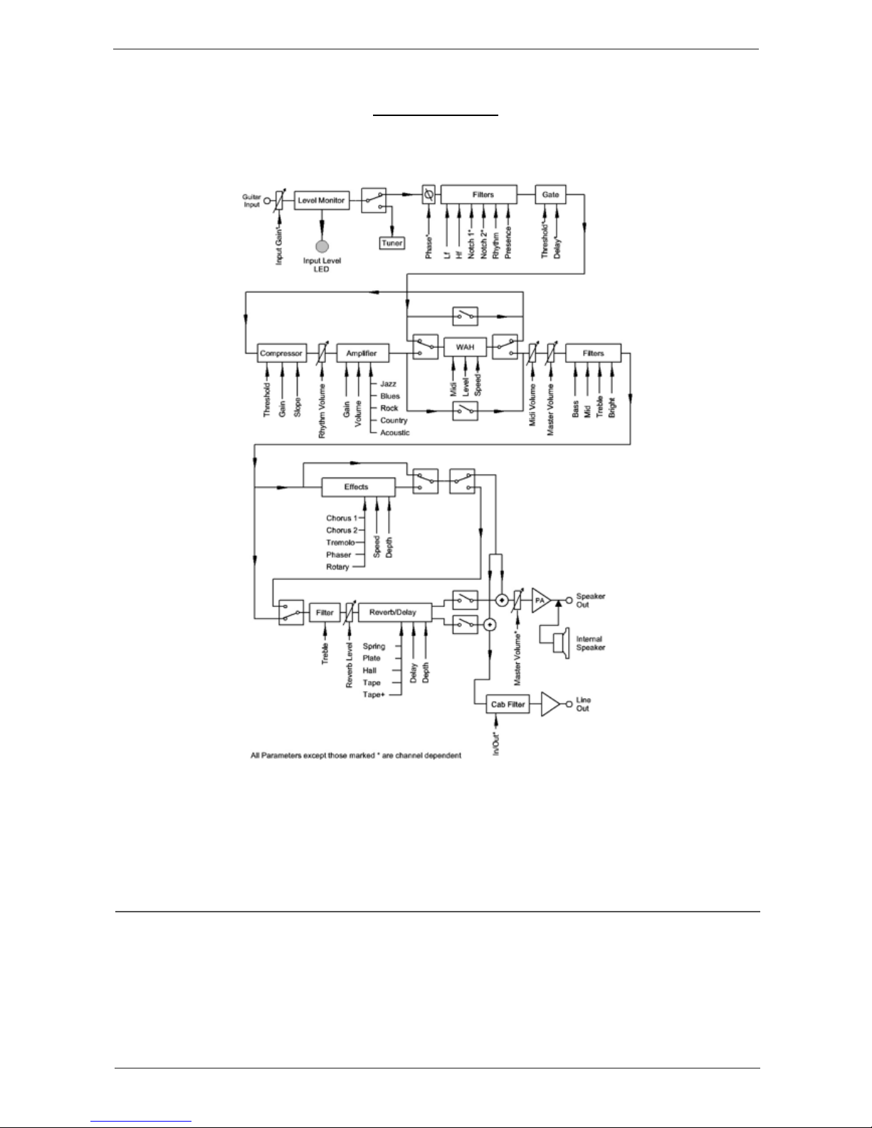
11. GP4 Signal Path
The information in this manual is subject to change without notice. No part of this manual may be
reproduced or transmitted in any form or by any means, electronic or mechanical, without the express
written permission of Hardman Guitar Amplifiers Ltd.
All Right Reserved © 2011 Hardman Guitar Amplifiers Ltd
 Loading...