

Harding Instruments Microcomm IEB-400 Installation Instructions Manual
IEB-400 Intercom Board
1. Intent & Scope
This document describes the installation procedure for the IEB-400 intercom board. The intercom board is used to
interface with 8 ohm intercom stations to obtain full MicroComm DXL quality and performance. The board can
also be used to transform 8 ohm ceiling loudspeakers and an external call switch into an intercom station.
2. Description
The IEB-400 intercom boards are connected to a DXI system via a SAB-400 or SAB-401 station audio board, or to a
DXL system via a SCC-400 or SCC-401 station control card. Each IEB-400 intercom station is connected to the
system via a 4-pin header and a single shielded twisted pair cable that carries all the microphone, loudspeaker,
switch, and LED indicator signals.
An 8-pin header is used to connect the IEB-400 intercom board to an 8 ohm loudspeaker, up to two switches and
an LED.
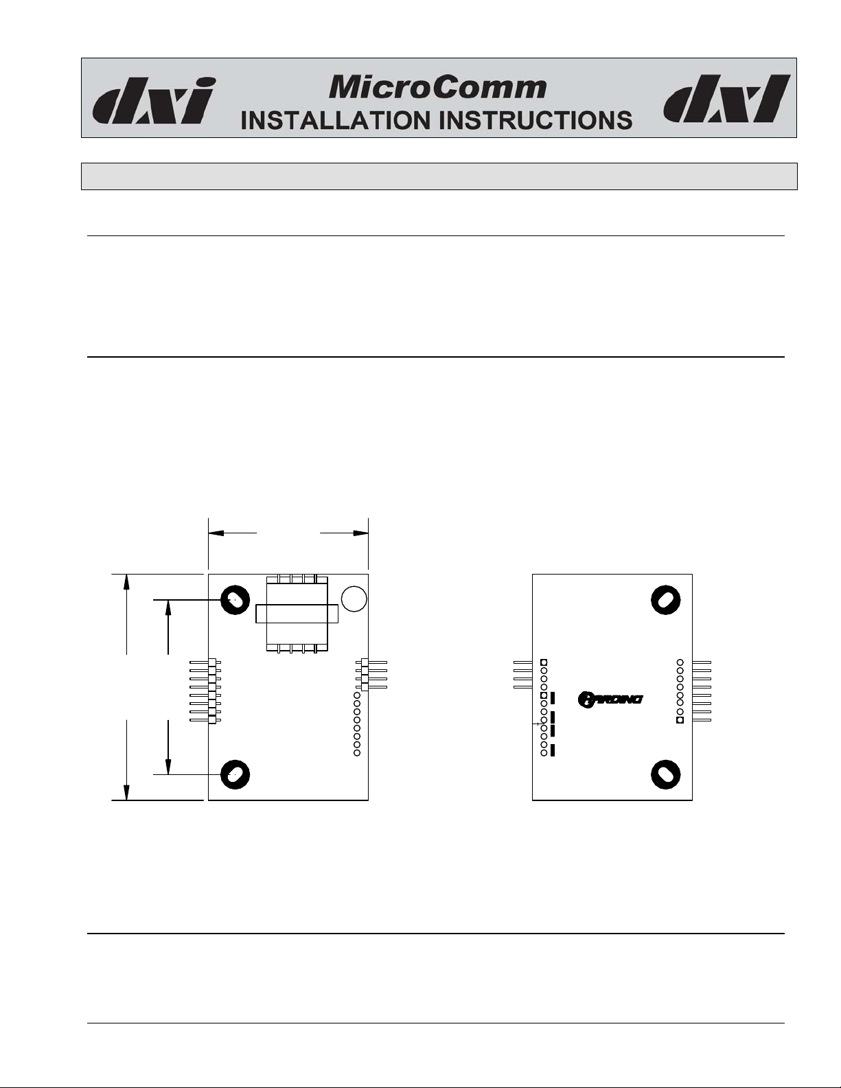
1.95"
PCB06741-06
MicroComm
ICE-400 Station
CN2
2.75"
2.13"
Component Side Back Side
Figure 1 IEB-400 showing Dimensions and Header Positions
3. Installation
ICE-400
Intercom Station
CN8
Pin 1
CN8
CN4
+
-
Line
+
SPK
SW
SW
SPK
SPK
SW
AB
SECONDARY
SW
SPK
PCB06741-06MicroComm
SPK
SPK
SWB+
SWB-
SWA+
SWALED+
LED-
CN2
Faceplate
Pin 1
A simplified diagram of an IEB-400 is shown in Figure 1. The 4-pin header CN8 connect the audio lines to the
DXL or DXI and the 8-pin header connects the loudspeaker, switch(es) and LED to the IEB-400 itself.
Document IM-IEB-400-1.1 2015 Harding Instruments - Printed in Canada
IEB 400 Intercom Board
3.1 Standard Station Audio Connections
Each IEB-400 intercom station is connected to the exchange with a single shielded twisted pair. The pair is
connected to terminals on the field interface terminal block. In turn these terminals are connected via a CBL-190 or
CBL-196 cable to the SCC-400 or SCC-401 in a DXL system. The shields are terminated at the field interface
terminal block and are grounded through the cable that connects the terminal block to the DXI or DXL exchange.
The audio line shielded twisted pair connects to pins 1 and 2 of a MTA-100-04 connector that plugs into CN8
header labeled Line. The shield is left open at the intercom station end of the cable.
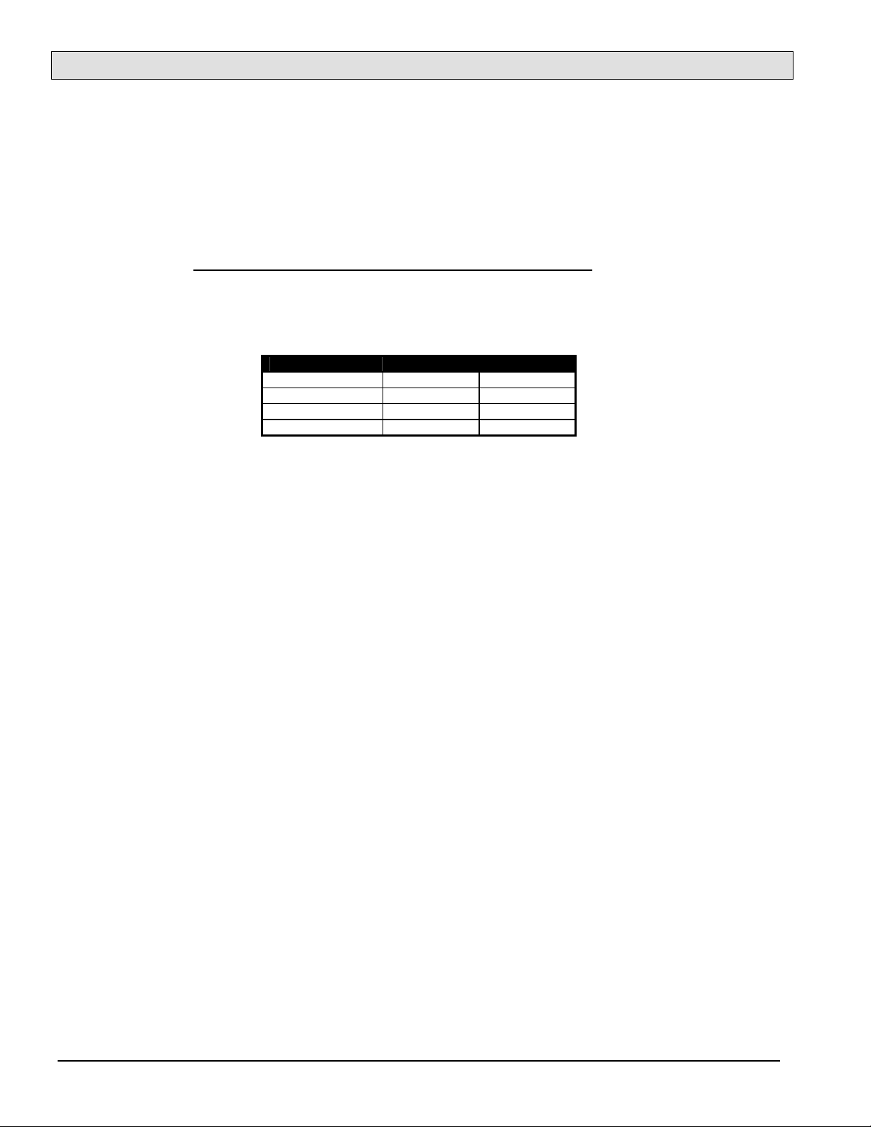
header and the corresponding MTA-100-04 connections are shown in the following table: The connector pin outs
are assigned so that the orientation of the mating connectors is reversible.
Connector Pin Signal MTA Pins
1 Line + Line +
2 Line - Line 3 Line - NC
4 Line + NC
Table 1 CN8 header pin signals
The pin assignments of CN8
The maximum recommended distance to run 22-gauge twisted-pair shielded cable from a 400 series station to
SAB-400, SAB-401, SCC-400 or SCC-401 is 2500 feet (750 meters).
3.2 Connections to an MTA Connector
The connections to the intercom station are made with an AMP MTA-100 series connector. The intercom pair
should connect to pins 1 and 2 on a female 4-pin AMP MTA-100 series connector that plugs onto the header CN8
labeled Line on the intercom station printed circuit board. To make these connections you should use an AMP
Handle Assy 58074-1 tool with a 58246-1 head. The cable should be cut to length and the shield and outer jacket
should be trimmed back about 1/2 inch. Ensure that the shield is not exposed or it may short out exposed contacts
on the intercom PCB when it is installed.
To insert the signal wires into the connector you remove the white cover from the connector, insert the connector
into the tool from the left side (it will travel through the tool in the direction indicated by the arrow), pull the
trigger once to load the connector. Then insert the signal wire for pin 1 (do not strip the wire) into the hole on the
top of the tool and pull the trigger to insert the wire into the connector. Then repeat to install the other signal wire.
Finally, remove the connector from the tool, replace the cover, and then slide the connector onto the pins on the
intercom station.
3.3 Connections to Loudspeaker, Switches and LED
The IEB-400 use one 8-pin MTA-100 header CN2 to connect the loudspeaker, switches and LED to the printed
circuit board. The pin assignments for the header are as follows.
Page 2 Document IM-IEB-400-1.1
 Loading...