

Hardinge Talent 6/45, Talent 8/52, Talent 8/66, Talent 10/78 Maintenance Manual
MAINTENANCE MANUAL
TP7086
®
TALENT
6/45
TALENT 8/52
TALENT 8/66
TALENT 10/78
CNC LATHES
Equipped with a Fanuc 0i-T,
Fanuc 0i Mate-T,
or Siemens 810D Control
Revised: March 31, 2006
Manual No. M-448B Litho in U.S.A.
Part No. M B-0009500-0448 January, 2006

- NOTICE -
Damage resulting from misuse, negligence, or accident is not covered by the
Hardinge Machine Warranty.
Information in this manual is subject to change without notice.
This manual covers the maintenance of Hardinge TALENT
equipped with a Fanuc 0i-T, Fanuc 0i Mate-T, or Siemens 810D control.
In no event will Hardinge Inc. be responsible for indirect or consequential
damage resulting from the use or application of the information in this man
ual.
Reproduction of this manual in whole or in part, without written permission
of Hardinge Inc., is prohibited.
CONVENTIONS USED IN THIS MANUAL
- WARNINGS -
Warnings must be followed carefully to avoid the possibility of personal injury or damage to the machine, tooling, or workpiece.
®
CNC lathes
-
- CAUTIONS -
Cautions must be followed carefully to avoid the possibility of damage to the
machine, tooling, or workpiece.
- NOTES -
Notes contain supplemental information.
Hardinge Inc.
One Hardinge Drive
P.O. Box 1507
Elmira, New York 14902-1507 U.S.A.
www.hardinge.com
© 2006, Hardinge Inc. M-448B

READ COMPLETE INSTRUCTIONS CAREFULLY
BEFORE OPERATING MACHINE OR BAR FEED SYSTEM
When this instruction book was printed, the information given was current. However, since we are
constantly improving the design of our machine tools and bar feed systems, it is possible that the
illustrations and descriptions may vary from the machine or bar feed system you received.
- WARNING -
Occupational Safety and Health Administration (OSHA) Hazard Communica
tion Standard 1910.1200, effective May 25, 1986, and various state “employee
right-to-know laws” require that information regarding chemicals used with
this equipment be supplied to you. Refer to the applicable section of the Ma
terial Safety Data Sheets supplied with your machine when handling, storing,
or disposing of chemicals.
Machine should only be used with a bar feed approved by Hardinge Inc.
-
-
HARDINGE SAFETY RECOMMENDATIONS
Your Hardinge machine is designed and built for maximum ease and safety of operation.
However, some previously accepted shop practices may not reflect current safety regulations and
procedures, and should be re-examined to insure compliance with the current safety and health
standards.
Hardinge Inc. recommends that all shop supervisors, maintenance personnel, and machine tool
operators be advised of the importance of safe maintenance, setup, and operation of Hardinge-built
equipment. Our recommendations are described below. READ THESE SAFETY
RECOMMENDATIONS BEFORE PROCEEDING ANY FURTHER.
READ THE APPROPRIATE MANUAL OR INSTRUCTIONS before attempting operation or
maintenance of the machine. Make certain that you understand all instructions.
DON’T ALLOW the operation or repair of equipment by untrained personnel.
CONSULT YOUR SUPERVISOR when in doubt as to the correct way to do a job.
WEAR SAFETY GLASSES AND PROPER FOOT PROTECTION at all times. When neces
sary, wear respirator, helmet, gloves, and ear muffs or plugs.
DON’T OPERATE EQUIPMENT unless proper maintenance has been regularly performed
and the equipment is known to be in good working order.
WARNING or INSTRUCTION TAGS are mounted on the machine for your safety and infor
mation. Do not remove them.
DON’T ALTER THE MACHINE to bypass any interlock, overload, disconnect, or other safety
device.
DON’T OPERATE EQUIPMENT if unusual or excessive heat, noise, smoke, or vibration oc
curs. Report any excessive or unusual vibration, sounds, smoke, or heat as well as any dam
aged parts.
-
-
-
-
REDUCE SPINDLE SPEED if vibration occurs. Bar stock straightness will have an effect on
vibration and balance of the spindle system.
M-448B i

NEVER OPERATE THE MACHINE SPINDLE without a work-holding device if the draw tube is
in the spindle.
TIGHTEN ALL DRAW TUBE SCREWS before beginning spindle operation.
MAKE CERTAIN that the equipment is properly grounded. Consult National Electric Code and
all local codes.
DISCONNECT MAIN ELECTRICAL POWER before attempting repair or maintenance.
ALLOW ONLY AUTHORIZED PERSONNEL to have access to enclosures containing electri
cal equipment.
DON’T REACH into any control or power case area unless electrical power is OFF.
DON’T TOUCH ELECTRICAL EQUIPMENT when hands are wet or when standing on a wet
surface.
REPLACE BLOWN FUSES with fuses of the same size and type as originally furnished.
ASCERTAIN AND CORRECT the cause of a shutdown caused by overload heaters before
restarting the machine.
KEEP THE AREA AROUND THE MACHINE well lighted and dry.
KEEP CHEMICAL AND FLAMMABLE MATERIAL away from electrical or operating equipment.
HAVE THE CORRECT TYPE OF FIRE EXTINGUISHER handy when machining combustible
material and keep chips clear of the work area.
DON’T USE a toxic or flammable substance as a solvent cleaner or coolant.
MAKE CERTAIN THAT PROPER GUARDING is in place and that all doors are closed and
secured.
-
TO REMOVE OR REPLACE the chuck closer it is necessary to remove the guard door at the
left end of the machine. Make certain that the guard door is in place before starting the machine.
DON’T OPEN GUARD DOORS while any machine component is in motion.
MAKE SURE chucks, closers, fixture plates, and all other spindle-mounted work-holding de
vices are properly mounted and secured before starting the machine.
MAKE CERTAIN all tools are securely clamped in position before starting the machine.
REMOVE ANY LOOSE PARTS OR TOOLS left on machine or in the work area before oper
ating the machine. Always check the machine and work area for loose tools and parts espe
cially after work has been completed by maintenance personnel.
REMOVE CHUCK WRENCHES before starting the machine.
BEFORE PRESSING THE CYCLE START PUSH BUTTON, make certain that proper func
tions are programmed and that all controls are set in the desired modes.
KNOW WHERE ALL stop push buttons are located in case of an emergency.
CHECK THE LUBRICATION OIL LEVEL and the status of the indicator lights before operat
ing the machine.
-
-
-
-
-
ii M-448B

MAKE CERTAIN that all guards are in good condition and are functioning properly before op
erating the machine.
-
INSPECT ALL SAFETY DEVICES AND GUARDS to make certain that they are in good con
dition and are functioning properly before the cycle is started.
CHECK THE POSITION of the tool top plate before pressing the Cycle Start push button.
CHECK SETUP, TOOLING, AND SECURITY OF THE WORKPIECE if the machine has been
OFF for any length of time.
DRY CYCLE a new setup to check for programming errors.
MAKE CERTAIN that you are clear of any “pinch point” created by moving slides before start
ing the machine.
DON’T OPERATE any equipment while any part of the body is in the proximity of a potentially
hazardous area.
DON’T REMOVE CHIPS with hands. Use a hook or similar device and make certain that all
machine movements have ceased.
BE CAREFUL of sharp edges when handling a newly machined workpiece.
DON’T REMOVE OR LOAD a workpiece while any part of the machine is in motion.
DON’T OPERATE ANY MACHINE while wearing rings, watches, jewelry, loose clothing, neck-
ties, or long hair not contained by a net or shop cap.
-
-
DON’T ADJUST tooling or coolant hoses while the machine is running.
DON’T LEAVE tools, workpieces or other loose items where they can come in contact with a
moving component of the machine.
DON’T CHECK finishes or dimensions of workpiece near running spindle or moving slides.
DON’T JOG SPINDLE in either direction when checking threads with a thread gage.
DON’T ATTEMPT to brake or slow the machine with hands or any makeshift device.
ANY ATTACHMENT, TOOL, OR MACHINE MODIFICATION not obtained from Hardinge Inc.
must be reviewed by a qualified safety engineer before installation.
USE CAUTION around exposed mechanisms and tooling especially when setting up. Be care
ful of sharp edges on tools.
DON’T USE worn or defective hand tools. Use the proper size and type for the job being per
formed.
USE ONLY a soft-faced hammer on tooling and fixtures.
DON’T USE worn or broken tooling on machine.
MAKE CERTAIN that all tool mounting surfaces are clean before mounting tools.
INSPECT ALL CHUCKING DEVICES daily to make certain that they are in good operating
condition. Replace any defective chuck before operating the machine.
-
-
USE MAXIMUM ALLOWABLE gripping pressure on the chuck. Consider weight, shape, and
balance of the workpiece.
M-448B iii

USE LIGHTER THAN NORMAL feedrates and depth of cut when machining a workpiece di
ameter that is larger than the gripping diameter.
DON’T EXCEED the rated capacity of the machine.
DON’T LEAVE the machine unattended while it is operating.
DON’T CLEAN the machine with an air hose.
KEEP TOTE PANS a safe distance from the machine. Don’t overfill the tote pans.
DON’T LET STOCK project past the back end of the chuck closer or machine spindle without
being adequately covered and properly supported.
FOLLOW each bar feed manufacturer’s guidelines. For performance and safe application,
size and use feed tube bushings, pushers, and spindle liners according to bar feed informa
tion.
MAKE CERTAIN that any bar feed mechanism is properly aligned with the spindle. If the bar
feed is a floor-mounted type, it must be securely bolted to the floor.
-
-
UNLESS OTHERWISE NOTED, all operating and maintenance procedures are to be per
formed by one person. To avoid injury to yourself and others, be sure that all personnel are
clear of the machine when opening or closing the coolant guard door and any access covers.
FOR YOUR PROTECTION - WORK SAFELY
-
iv M-448B

Table of Contents
CHAPTER 1 - POWER-UP, POWER-DOWN, AND LOCK-OUT PROCEDURES
Machine Equipped with a Fanuc Control......................1-1
Power-Up Procedure .............................1-1
Reference Home Procedure ..........................1-2
Power-Down Procedure ............................1-3
Machine Equipped with a Siemens Control ....................1-4
Power-Up Procedure .............................1-4
Power-Down Procedure ............................1-4
Air and Electrical Lock-Out Procedures ......................1-5
Air Lock-Out Procedure ............................1-5
Electrical Lock-Out Procedure .........................1-5
Clearing an Emergency Stop ...........................1-6
Hour Run Meter .................................1-6
CHAPTER 2 - LUBRICATION
Introduction ...................................2-1
Importance of Lubrication ............................2-1
Recommended Grease..............................2-1
Lubrication Alarm ................................2-2
Grease Volume .................................2-2
Axis Lubrication .................................2-3
X and Z Axis Lubrication on TALENT
X and Z Axis Lubrication on TALENT 8/66 and 10/78 Lathes ..........2-4
Tailstock Lubrication on TALENT 6/45 and 8/52 Lathes .............2-5
Tailstock Lubrication on TALENT 8/66 and 10/78 Lathes ............2-6
Live Tool Gear Lubrication ............................2-7
Lubrication Line Replacement ..........................2-8
Replacement Part Numbers ..........................2-8
Replacing a Lubrication Line .........................2-8
®
6/45 and 8/52 Lathes ..........2-3
CHAPTER 3 - AIR SYSTEM
System Description ...............................3-1
Standard Configuration ............................3-1
Optional Configuration ............................3-1
Setting the Air Pressure .............................3-2
Maintenance ..................................3-2
Air Filter/Regulator ..............................3-2
Air Line Lubricator ..............................3-3
Approved Air System Oils ...........................3-3
M-448B v

CHAPTER 4 - COOLANT SYSTEM
Introduction ...................................4-1
System Description ...............................4-2
Water-Based Coolants ..............................4-2
Concentration ................................4-2
pH......................................4-3
Water Quality ................................4-3
Care and Maintenance ............................4-3
Checking the Coolant Level ...........................4-4
Chip Removal ..................................4-5
TALENT
®
6/45 and 8/52 Lathes ........................4-5
TALENT 8/66 and 10/78 Lathes ........................4-5
Cleaning the Coolant Tank ............................4-6
TALENT 6/45 and 8/52 Lathes ........................4-6
TALENT 8/66 and 10/78 Lathes ........................4-7
Replacing the Coolant Pump ...........................4-9
CHAPTER 5 - HYDRAULIC SYSTEM
Introduction ...................................5-1
Hydraulic Tank .................................5-2
Filling the Hydraulic Tank ...........................5-2
Approved Hydraulic System Oils ........................5-2
Draining and Filling the Hydraulic Tank.....................5-3
Adjusting the Hydraulic System Pressure .....................5-4
CHAPTER 6 - MISCELLANEOUS
Battery Maintenance ...............................6-1
Turret Controller Battery Replacement (Non-Live Tooling Machines Only).....6-1
CNC Control Battery Replacement (Fanuc Control Only) ............6-3
Control Configurations ...........................6-3
Fanuc 0i Mate-T Control ..........................6-3
Fanuc 0i-T Control.............................6-5
Turret Zero Reference ..............................6-6
Adjusting the Tailstock Bushing for Center .....................6-8
Cleaning the Power Case Heat Exchanger Air Filter ................6-9
Cleaning the Power Case Plenum Fan Air Filter ..................6-10
APPENDIX ONE - PREVENTIVE MAINTENANCE SCHEDULE
Cleaning the Machine ..............................A1-1
Maintenance Schedule ..............................A1-1
APPENDIX TWO - MACHINE PHOTOGRAPHS
vi M-448B

- NOTES -
M-448B vii

- NOTES -
viii M-448B
CHAPTER 1 - POWER-UP, POWER-DOWN,
AND LOCK-OUT PROCEDURES
- CAUTION -
The recommended operating temperature range is 50° to 95° F [7° to 35° C].
MACHINE EQUIPPED WITH A FANUC CONTROL
- NOTE -
Information relating to machines equipped with a Siemens control begins on page
1-4.
POWER-UP PROCEDURE
- NOTE -
It is important that the power-up procedure is followed as described to ensure safe,
accurate, and repeatable machine operation.
1. Close the main guard door.
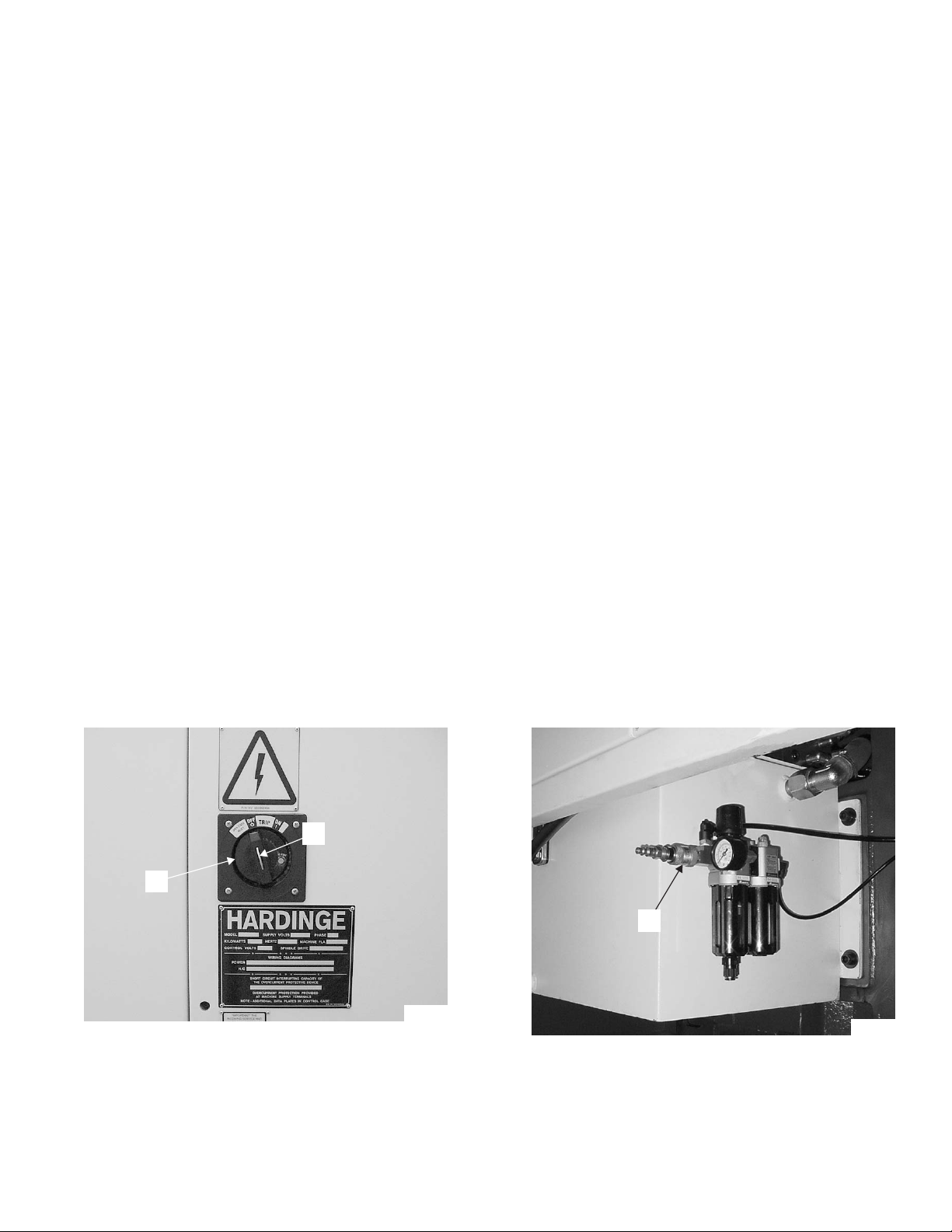
2. Turn main disconnect switch “A”, Figure 1.1, ON.
3. If the machine is equipped with the optional parts catcher, turn main air valve “C”, Figure 1.2,
ON.
4. Check the coolant level. Refill as needed.
5. Check the hydraulic oil level. Refill as needed.
B
A
TP5053
Figure 1.1 - Main Disconnect Switch
C
TP5040
Figure 1.2 - Air Filter Regulator for
Optional Parts Catcher
M-448B 1-1

- CAUTION -
When pressing the Control ON push button, DO NOT press any other push
buttons or keys until the position or alarm screen is displayed. Some push
buttons and keys are used for control maintenance or special operation commands.
- NOTE -
TALENT
®
6/45SV and 8/52SV lathes are not equipped with Control ON/OFF push
buttons. Step 6 will be omitted.
6. Press the Control ON push button and wait until the control display screen is ON.
7. Pull the Emergency Stop push button out and release.
8. Open and close the coolant guard door to perform the guard door switch verification and clear
the verification alarm.
9. Press the Work Light push button.
10. The machine is now ready for the Reference Home procedure.
REFERENCE HOME PROCEDURE
- CAUTION -
When homing the axes, be sure that no interference exists between the
workpiece, spindle tooling, optional tailstock, or turret tooling.
- NOTE -
The X and Z axes must both be jogged approximately 1 inch [25 millimeters] in the
minus direction before a Reference Home can be performed.
The optional tailstock must be at Home position before the X and Z axes can be
homed.
1. Set the Mode Select switch to Jog mode.
2. If the lathe is equipped with the optional tailstock:
Verify the tailstock is at the Home position.
If necessary, turn the Tailstock Jog switch to the right to move the tailstock to the Home
position.
3. Set the Feedrate switch to any setting above 0 (zero).
4. Press and hold the -X push button to jog the turret approximately 1 inch [25 millimeters] in the
minus direction.
5. Press and hold the -Z push button to jog the turret approximately 1 inch [25 millimeters] in the
minus direction.
6. Set the Mode Select switch to Reference mode.
1-2 M-448B
Revised: March 31, 2006

- NOTE -
The X axis must be “homed” before the Z axis is “homed” on machines equipped
with a tailstock.
7. Press the +X push button. The X axis will move to the X Home position and the X Home
indicator light will turn ON.
8. Press the +Z push button. The Z axis will move to the X Home position and the X Home
indicator light will turn ON.
9. If the machine is equipped with the live tooling option, reference the turret as follows:
A) Set the Turret Station selector switch to any station not at the active position.
B) Press the Turret Index push button.
POWER-DOWN PROCEDURE
1. Be sure “Cycle Start” is not active. The Cycle Start push button light will be OFF.
2. Be sure the program has been completed and that the spindle and slides are stationary.
3. Press the Emergency Stop push button.
4. Press the Control OFF push button.
5. Turn main air valve “C”, Figure 1.2, OFF.
6. Turn main disconnect switch “A”, Figure 1.1, OFF.
7. If necessary, lock out the main air valve and main disconnect switch, as outlined on page 1-5.
M-448B 1-3

MACHINE EQUIPPED WITH A SIEMENS CONTROL
- NOTE -
Information relating to machines equipped with a Fanuc control begins on page
1-1.
POWER-UP PROCEDURE
- NOTE -
It is important that the power-up procedure is followed as described to ensure safe,
accurate, and repeatable machine operation.
1. Close the main guard door.
2. Turn main disconnect switch “A”, Figure 1.1, ON.
3. If the machine is equipped with the optional parts catcher, turn main air valve “C”, Figure 1.2,
ON.
4. Check the coolant level. Refill as needed.
5. Check the hydraulic oil level. Refill as needed.
- NOTE -
The machine will power up in the ShopTurn mode.
WAIT until the following alarm message is displayed before proceeding to Step 4:
“3000ê EMERGENCY STOP”
6. Press the Reset push button to clear the Emergency Stop.
7. Open and close the coolant guard door to perform the guard door switch verification and clear
the verification alarm.
8. Press the Axis Home push button. The Axis Home indicator light will start flashing and the X and
Z axes will automatically home.
POWER-DOWN PROCEDURE
1. Be sure “Cycle Start” is not active. The Cycle Start push button light will be OFF.
2. Be sure the program has been completed and that the spindle and slides are stationary.
3. Press the Emergency Stop push button.
4. Turn main air valve “C”, Figure 1.2, OFF.
5. Turn main disconnect switch “A”, Figure 1.1, OFF.
6. If necessary, lock out the main air valve and main disconnect switch, as outlined on page 1-5.
1-4 M-448B

AIR AND ELECTRICAL LOCK-OUT PROCEDURES
- NOTE -
The air lock-out procedure applies only to machines equipped with the optional
parts catcher.
AIR LOCK-OUT PROCEDURE
1. Turn main air valve “C”, Figure 1.2, OFF.
2. Place a lock on the main air valve to prevent the valve from being turned ON.
ELECTRICAL LOCK-OUT PROCEDURE
1. Turn main disconnect switch “A”, Figure 1.1, OFF.
2. Pull lock out tab “B” out.
3. Lock out the main disconnect handle through tab “B”.
M-448B 1-5

CLEARING AN EMERGENCY STOP
The Emergency Stop pish button is located on the operator control panel.
1. Correct the problem that prompted the Emergency Stop condition.
2. Pull the Emergency Stop push button out and release.
HOUR RUN METER
- NOTE -
TALENT
Hour Run meter “D”, Figure 1.3, Is located on the right side of the operator control panel. It records
the amount of time the control has been powered up.
®
6/45SV and 8/52SV lathes are not equipped with an Hour Run meter.
D
Figure 1.3 - Hour Run Meter
(Fanuc Control Shown)
TP5197
1-6 M-448B

- NOTES -
M-448B 1-7

- NOTES -
1-8 M-448B

CHAPTER 2 - LUBRICATION
INTRODUCTION
TALENT®CNC lathe axes are grease lubricated at grease blocks mounted on the right side of the
carriage. The grease system lubricates the ball screws and truck bearings on the linear guideways.
Fresh grease should be added every 600 hours of machine operation or more frequently under
severe operating conditions.
When the grease lubrication system requires maintenance, the machine must be powered down.
Refer to Chapter 1 for the power-up, power-down, and lock-out procedures.
IMPORTANCE OF LUBRICATION
Running conditions of this machine depend heavily upon the lubrication management. Make
certain that the lubrication system is checked frequently under severe operating conditions to keep
the machine in proper working condition.
RECOMMENDED GREASE
The following greases are recommended by Hardinge Inc. for use on the TALENT CNC lathe.
Grease
®
KLÜBER
KLÜBER Isoflex NBU 15 HS 00010994SL
Other greases may not contain certain additive packages needed for proper lubrication and
performance. The additive packages may include rust inhibitors, corrosion inhibitors, and anti-wear
compounds, which have been blended specifically for that application. Although many companies
offer “similar” greases, these may not contain the needed additives to ensure maximum performance
and protection of Hardinge machines.
Isoflex NCA 15 TT 0010994NCA
Hardinge Grease
Cartridge Part Number
M-448B 2-1

LUBRICATION ALARM
The control issues the following lubrication alarms:
• Axis lubrication alarm message after 600 hours of operation.
• Turret lubrication alarm message after 2000 hours of operation. (Live tooling machines
only)
A lubrication alarm does not stop the machine, but will inhibit Cycle Start.
Clear the alarm message as follows:
If the machine is equipped with a Fanuc control, press the Feed Hold and Reset push buttons at the same time to clear the alarm.
If the machine is equipped with a Siemens control, press the Reset key AND HOLD FOR 5
SECONDS to clear the alarm.
GREASE VOLUME
The grease volume presented is dependent upon the grease gun being used. Carefully measure
the amount of grease or count the grease gun strokes necessary to lubricate the guides and ball
screws. Be certain that all air is purged from any grease gun before use.
- NOTE -
The grease gun supplied with the machine delivers 3 cc per full stroke.
The required amount of grease is:
Linear Guides: 3½ cc
Ball Screws: 11 cc
Make certain that all the sliding surfaces are lubricated well by jogging the axes at 50% of the
maximum rapid traverse for a full 30 minutes before resuming automatic operation.
2-2 M-448B
AXIS LUBRICATION
- NOTE -
Grease should be added when the linear guides are still warm from operation.
X AND Z AXIS LUBRICATION ON TALENT
1. Wait for the cycle to end and that the spindles
and slides are stationary.
- NOTE -
Refer to the Operator’s Manual
(M-447) for information on using Rapid
Reference to move axes to the reference position.
2. Move the Z axis to the reference position.
3. Power down and lock out the machine. Refer to
the appropriate power-down procedure in
Chapter 1.
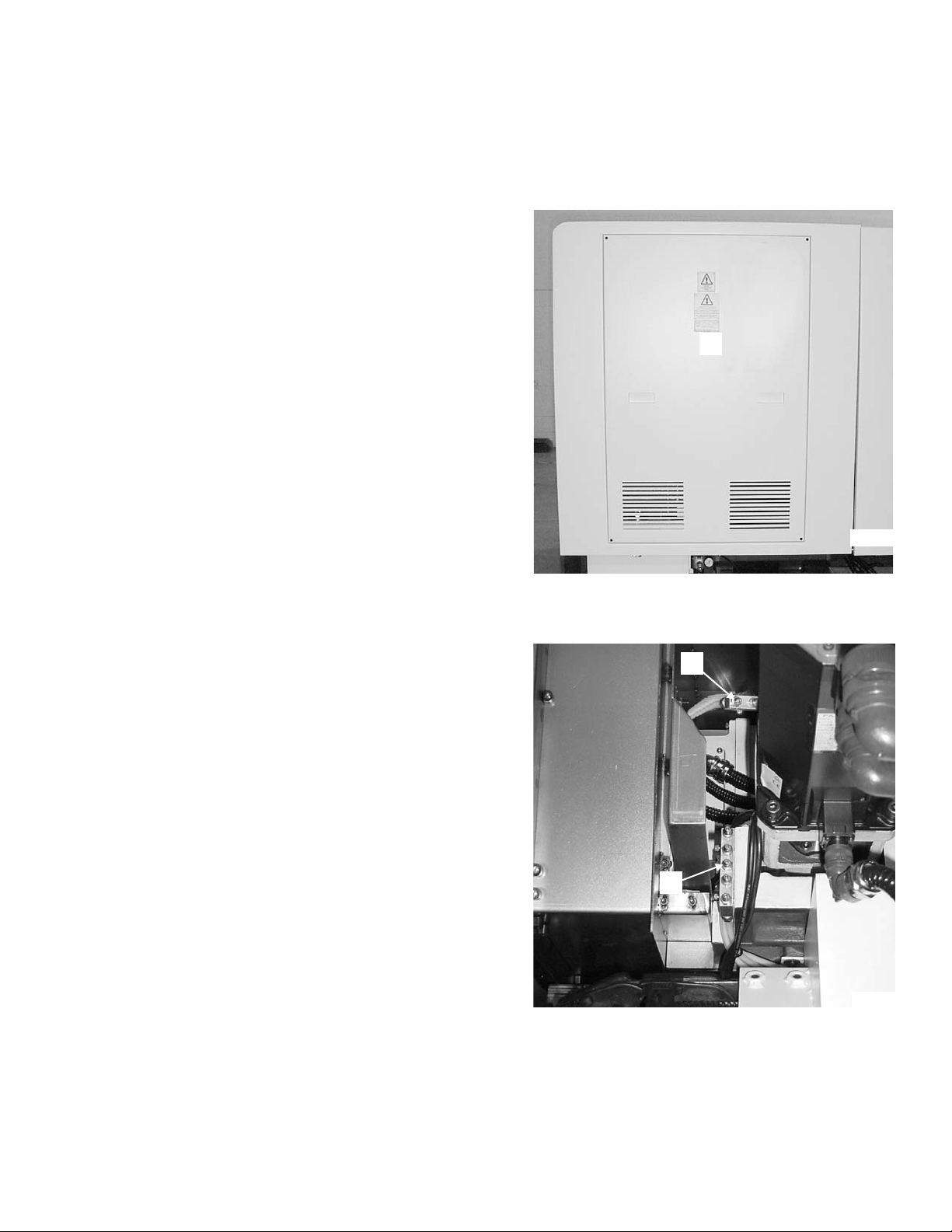
4. Remove cover “A”, Figure 2.1, to gain access
to the fittings on grease manifolds “B” and “C”,
Figure 2.2.
5. Clean the grease fittings.
- NOTE -
Only use a manually operated grease
gun.
Manifold “B” supplies grease to the X
axis. Manifold “C” supplies grease to
the Z axis.
®
6/45 AND 8/52 LATHES
Figure 2.1 - Rear Access Cover
A
TP5196
B
6. Attach the grease gun nozzle to each grease
fitting; slowly and evenly pump in the specified
amount of grease.
7. Wipe the fittings clean of excess grease.
8. Install cover “A”, Figure 2.1.
9. Power up the machine. Refer to the
C
appropriate power-up procedure in Chapter 1.
10. If necessary, clear the lubrication alarm as
outlined in "Lubrication Alarm", page 2-2.
11. Jog the axes at 50% of the maximum rapid
traverse for a full 30 minutes before resuming
automatic machine operation.
M-448B 2-3
Figure 2.2 - Grease Manifolds
TP5038
X AND Z AXIS LUBRICATION ON TALENT®8/66 AND 10/78 LATHES
1. Wait for the cycle to end and that the spindles
and slides are stationary.
- NOTE -
Refer to the Operator’s Manual
(M-447) for information on using Rapid
Reference to move axes to the reference position.
2. Move the Z axis to the reference position.
3. Power down and lock out the machine. Refer to
the appropriate power-down procedure in
Chapter 1.
4. Remove cover "A", Figure 2.1, to gain access
to the X and Z axis grease fittings.
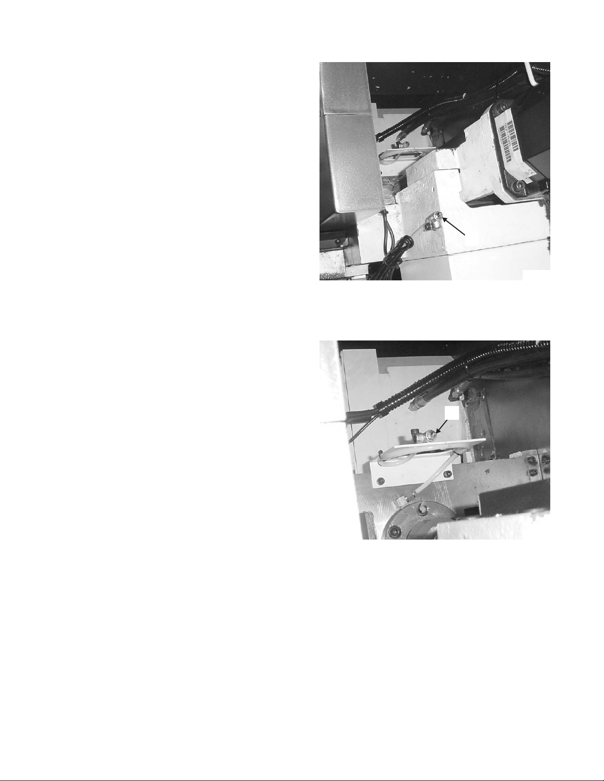
5. Clean Z axis grease fitting "D", Figure 2.3, and
X axis grease fitting "E", Figure 2.4.
- NOTE -
Only use a manually operated grease
gun.
6. Attach the grease gun nozzle to each grease
fitting; slowly and evenly pump in the specified
amount of grease.
7. Wipe the fittings clean of excess grease.
8. Replace cover “A”, Figure 2.1.
9. Power up the machine. Refer to the
appropriate power-up procedure in Chapter 1.
10. If necessary, clear the lubrication alarm as
outlined in "Lubrication Alarm", page 2-2.
11. Jog the axes at 50% of the maximum rapid
traverse for a full 30 minutes before resuming
automatic machine operation.
D
TP6034
Figure 2.3 - Z Axis Grease Fitting
E
TP6035
Figure 2.4 - X Axis Grease Fitting
2-4 M-448B
TAILSTOCK LUBRICATION ON TALENT®6/45 AND 8/52 LATHES
1. Wait for the cycle to end and that the spindles
and slides are stationary.
- NOTE -
Refer to the Operator’s Manual
(M-447) for information on using Jog
mode to move the tailstock.
2. Move the tailstock toward the guard door
opening to gain access to cover “F”, Figure 2.5.
3. Power down and lock out the machine. Refer to
the appropriate power-down procedure in
Chapter 1.
4. Remove cover “F”, Figure 2.5, to gain access
to the fittings on grease manifold “G”, Figure
2.6.
Figure 2.5 - Grease Manifold Access
Cover on Tailstock
5. Clean the grease fittings.
- NOTE -
Only use a manually operated grease
gun.
F
TP5256
6. Attach the grease gun nozzle to each grease
fitting; slowly and evenly pump in the specified
amount of grease.
7. Wipe the fittings clean of excess grease.
8. Replace cover “F”, Figure 2.5.
9. Power up the machine. Refer to the
appropriate power-up procedure in Chapter 1.
10. Move the tailstock to the fixed Home position.
11. If necessary, clear the lubrication alarm as
outlined in "Lubrication Alarm", page 2-2.
G
TP5223
Figure 2.6 - Tailstock Grease Manifold
M-448B 2-5

TAILSTOCK LUBRICATION ON TALENT®8/66 AND 10/78 LATHES
1. Wait for the cycle to end and that the spindles and slides are stationary.
- NOTE -
Refer to the Operator’s Manual (M-447) for information on using Jog mode to move
the tailstock.
2. Move the tailstock toward the guard door opening to gain access to grease fitting “H”, Figure
2.7.
3. Power down and lock out the machine. Refer to the appropriate power-down procedure in
Chapter 1.
4. Clean the grease fitting.
- NOTE -
Only use a manually operated grease gun.
5. Attach the grease gun nozzle to the grease fitting; slowly and evenly pump in the specified
amount of grease.
6. Wipe the fitting clean of excess grease.
7. Power up the machine. Refer to the appropriate power-up procedure in Chapter 1.
8. Move the tailstock to the fixed Home position.
9. If necessary, clear the lubrication alarm as outlined in "Lubrication Alarm", page 2-2.
H
TP6037
Figure 2.7 - Tailstock Grease Fitting
2-6 M-448B

LIVE TOOL GEAR LUBRICATION
- NOTE -
Use Klübersynth UH1 14-1600 grease for live tool gear lubrication.
The live tool gear lubrication should be checked every 2000 hours of machine operation.
1. Remove plug screw "I", Figure 2.8 or 2.9.
2. Insert a thin tool into the turret, as shown in Figure 2.10, and touch the live tool gear.
- CAUTION -
Contact a Duplomatic Service Center if metallic dust, coolant, or oil is detected in the grease.
3. Check the tool tip for the presence of grease:
If grease is detected, no action is required.
If grease is not detected, add 2 ~ 2.4 in
4. Replace the plug screw.
5. If necessary, clear the lubrication alarm as outlined in "Lubrication Alarm", page 2-2.
3
[30 ~ 40 cm3] of grease as shown in Figure 2.11.
I
Figure 2.8 - Grease Plug Location
(TALENT
®
6/45 and 8/52 Lathes)
Figure 2.10 - Checking the Grease
TP7097
TP7098
I
TP7100
Figure 2.9 - Grease Plug Location
(TALENT 8/66 and 10/78 Lathes)
TP7099
Figure 2.11 - Adding Grease
M-448B 2-7

LUBRICATION LINE REPLACEMENT
REPLACEMENT PART NUMBERS
Grease Manifold TT 0010234
Tubing TT 0007007
REPLACING A LUBRICATION LINE
1. Wait for the cycle to end and make certain that the spindle is stopped.
2. Remove cover “A”, Figure 2.1, to gain access to the grease manifolds and grease lines.
3. Jog each axis until the grease/lubrication lines are accessible.
4. Power down and lock out the machine. Refer to the appropriate power-down procedure in
Chapter 1.
- NOTE -
Replace the lubrication lines one line at a time.
The ball screw lubrication lines connect to the middle fitting (marked “BS”) on each
grease manifold.
5. Check each lubrication line for damage. Before disconnecting the line being replaced, measure
the length and check the route from the grease manifold to either the linear guide or ball screw.
6. Disconnect the lubrication line and compare the length of the old lubrication line and the
replacement lubrication line.
7. Before installing the replacement line, fill the line with KLÜBER
®
Isoflex NCA 15 or NBU 15
grease.
8. Install the replacement lubrication line:
A) Connect one end of the replacement lubrication line at the grease manifold.
B) Add the specified grease through its fitting until grease appears at the other end of the
lubrication line.
C) Connect that end of the lubrication line.
9. Wipe the fittings clean of excess grease.
10. Install cover “A”, Figure 2.1.
11. Power up the machine. Refer to the appropriate power-up procedure in Chapter 1.
12. Jog the axes at 50% of the maximum rapid traverse for a full 30 minutes before resuming
automatic machine operation.
2-8 M-448B

- NOTES -
M-448B 2-9

- NOTES -
2-10 M-448B
CHAPTER 3 - AIR SYSTEM
SYSTEM DESCRIPTION
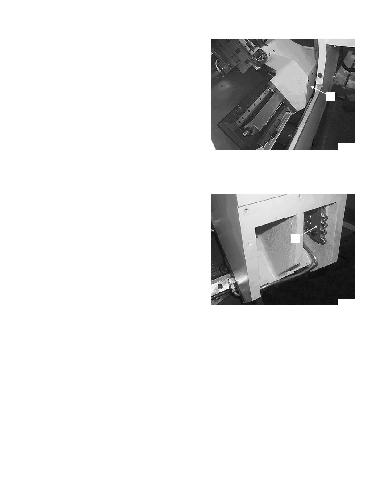
The air connection is located at the rear of the machine near the lower left corner. It is mounted on
the side of the hydraulic tank, as shown in Figure 3.1 or 3.2.
The incoming air line should have a minimum inside diameter of 3/8 inch [9.5 mm].
Air is supplied to the following:
The air nozzle located on the front of the machine below the operator control panel
•
The optional parts catcher
•
STANDARD CONFIGURATION
Standard machines are equipped with a quick disconnect fitting, as shown in Figure 3.1.
OPTIONAL CONFIGURATION
- NOTE -
The air filter/regulator is equipped with an automatic drain.
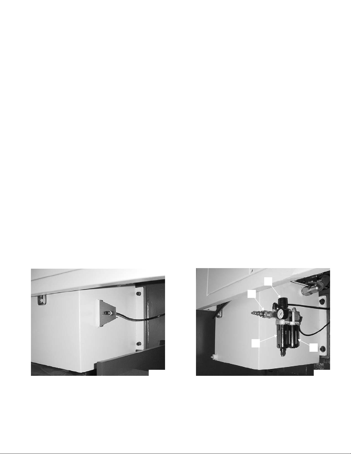
Machines equipped with the optional parts catcher are equipped with a quick-disconnect fitting,
ON-OFF air valve, air filter/regulator, and air line lubricator, as shown in Figure 3.2. An air dryer may
have to be added in the air line if the factory air has excessive moisture.
When a machine equipped with the optional parts catcher is powered up, turn ON the air source
and set regulator knob “A”, Figure 3.2, at a constant pressure from 70 psi to 90 psi [4.9 to 6.2 bars].
A
B
C
TP5219
D
TP5040
Figure 3.1 - Air Connection
(Machine without Optional Part Catcher)
M-448B 3-1
Figure 3.2 - Air Connection
(Machine with Optional Part Catcher)
SETTING THE AIR PRESSURE
- NOTE -
This information applies only to machines equipped with the optional part catcher.
1. Turn main air valve “B”, Figure 3.2, ON.
2. Lift knob “A” up to unlock.
3. Rotate the knob in the appropriate direction to increase or decrease pressure, as needed.
Observe the air pressure on the gauge.
4. Press knob “A” down to secure the pressure setting.
MAINTENANCE
- WARNING -
Turn the air valve OFF and lock out before performing air system maintenance. Refer to page 1-5 for the air system lock-out procedure.
- NOTE -
This information applies only to machines equipped with the optional part catcher.
Air system maintenance consists of the following:
• Cleaning the air system bowls
• Replacing the air filter
• Replacing the air lubrication oil
AIR FILTER/REGULATOR
1. Turn main air valve “B”, Figure 3.2, OFF and lock out.
- NOTE -
Notice the orientation of the locking lugs on the filter bowl when it releases from
the filter/regulator head.
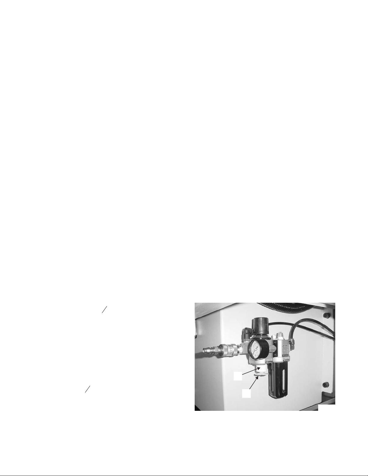
2. Twist filter bowl “C”
1
turn in either direction to
8
release the bowl from the filter/regulator head.
3. Clean the bowl with a lint-free cloth.
4. Unthread filter retainer “F” and remove air filter
“E”, Figure 3.3.
5. Install the replacement air filter and the filter
retainer.
6. Insert the bowl into the filter/regulator head and
twist the bowl
1
turn in either direction to lock
8
the bowl in position.
E
F
TP5246
Figure 3.3 - Air Filter
and Filter Retainer
3-2 M-448B
 Loading...