

Hardinge T-51, T-65, T-42 Installation And Extended Storage Instructions
INSTALLATION AND
EXTENDED STORAGE INSTRUCTIONS
Multi-Tasking CNC Lathes
READ THE ENCLOSED INFORMATION BEFORE
REMOVING THE MACHINE FROM THE SKID.
Revised: July 25, 2012
TI7878A
T-42
T-51
T-65
ATTENTION
Original Instructions
Manual No. M-507C Litho in U.S.A.
Part No. M C-0009500-0507 April, 2012

- NOTICE -
Damage resulting from misuse, negligence, or accident is not covered by the
Hardinge Machine Warranty.
Information in this manual is subject to change without notice.
This manual covers the installation and extended storage of Hardinge
T-42, T-51, and T-65 Multi-Tasking CNC lathes.
In no event will Hardinge Inc. be responsible for indirect or consequential
damage resulting from the use or application of the information in this man
ual.
Reproduction of this manual in whole or in part, without written permission
of Hardinge Inc., is prohibited.
CONVENTIONS USED IN THESE INSTRUCTIONS
- WARNINGS -
Warnings must be followed carefully to avoid the possibility of personal injury or
damage to the machine, machine attachments, tooling, or workpiece.
-
- CAUTIONS -
Cautions must be followed carefully to avoid the possibility of damage to the machine, machine attachments, tooling, or workpiece.
- NOTES -
Notes contain supplemental information.
© 2012, Hardinge Inc. M-507C

Table of Contents
Offices ........................................... iii
Machine Description and Intended Use .......................... iv
Warnings .......................................... v
CHAPTER 1 - INSTALLATION
Machine Installation Requirements ............................ 1-1
Foundation Requirements............................... 1-1
Approximate Weight.................................. 1-1
Machine Dimensions ................................... 1-2
T-42 and T-42 Big-Bore Lathes ............................ 1-2
T-51 and T-65 Lathes ................................. 1-3
Setting the Machine ................................... 1-5
Securing the Machine to the Floor ............................ 1-6
Shipping Brackets .................................... 1-8
Shipping Bracket Locations .............................. 1-8
Removing the Pendant Shipping Bracket .......................1-9
Removing the Guard Door Shipping Bracket (T-51 and T-65 Lathes) ........1-9
Removing the Guard Support Brackets (T-51 and T-65 Lathes)...........1-10
Removing the Platform and Carriage Shipping Brackets ..............1-11
Installing the Interlock Switch on the Rear Access Door ................1-12
Power Case Platform .................................. 1-13
Mounting the Control Pendant in Operating Position .................. 1-15
Cleaning the Machine .................................. 1-18
Air Connection...................................... 1-19
Connecting the Air Supply .............................. 1-19
Setting the Machine Air Pressure .......................... 1-19
Spindle Chiller Installation................................ 1-20
Coolant Tank Installation ................................ 1-24
Coolant Chiller Installation................................ 1-28
Installing the Chiller Unit Fuses ............................. 1-31
Coolant ......................................... 1-33
Water-Based Coolants................................ 1-33
Filling the Coolant Tank ............................... 1-33
Grounding the Machine ................................. 1-34
Supplemental Earth Ground ............................. 1-34
System Ground ................................... 1-35
Electrical Power Connection .............................. 1-35
Electrical Requirements ............................... 1-35
Line Configuration for European Machine Installation ................1-36
Connect the Electrical Supply ............................ 1-37
Electrical Phase ................................... 1-38
Checking the Electrical Phase .......................... 1-38
Changing the Electrical Phase .......................... 1-38
M-507C i

Hydraulic System .................................... 1-39
Hydraulic Tank Fluid Capacity ............................ 1-39
Filling the Hydraulic Tank .............................. 1-39
Foot Switch Installation ................................. 1-40
Option Interface Receptacles .............................. 1-41
Non-Metallic Materials Typically Found in Hardinge Machine Construction.......1-41
CHAPTER 2 - EXTENDED STORAGE
Battery Maintenance ................................... 2-1
Control Battery .................................... 2-1
Axis Drive Batteries .................................. 2-3
Lubrication ........................................ 2-5
Lubrication Procedure................................. 2-6
Apply Rust Inhibitor .................................... 2-8
Clean the Spindle(s) ................................... 2-8
Clean the Air Filter Bowls ................................ 2-11
Coolant System ..................................... 2-12
Clean the Coolant Filter ............................... 2-12
Clean the Coolant Tank ............................... 2-13
Clean the Main Spindle Coolant Catcher ...................... 2-20
Hydraulic System .................................... 2-21
Spindle Chiller ...................................... 2-23
Coolant Chiller...................................... 2-25
Removing the Machine Hold-Down Brackets ......................2-26
Shipping Restraints ................................... 2-27
Install the Shipping Tubes .............................. 2-27
Install the Shipping Brackets............................. 2-29
Electrical and Air Supplies................................ 2-33
Electrical Lockout .................................. 2-33
Air Lockout...................................... 2-33
DOCUMENT REVISION RECORD
ii M-507C

Global Headquarters
United States Hardinge Inc.
Hardinge Subsidiaries
England Bridgeport
Germany Hardinge GmbH
OFFICES
One Hardinge Drive
Elmira, NY 14902-1507 USA
Telephone: 607-734-2281
web site: www.hardinge.com
Hardinge Machine Tools, Ltd.
Whiteacres
Cambridge Road
Whetstone
Leicester
LE8 6BD England
Telephone: +44 (0)116 2869900
web site: www.bpt.com
email: sales@bpt.com
Saalestrasse 20
47800 Krefeld
Germany
Telephone: (49) 2151 496490
Distributor
China Hardinge Machine (Shanghai) Co. Ltd.
Hardinge China Limited
No.1388 East Kang Qiao Road
Pudong , Shanghai 201319
Telephone : 0086 21 38108686
web site: www.hardinge.com.cn
Taiwan Hardinge Taiwan Precision Machinery Ltd.
4 Tzu Chiang 3rd Road
Nan Tou City
540 Taiwan, R.O.C.
Telephone: 886-49-226-0536
France Delta Machines
3 Rue du Docteur Charcot
F-91422 Morangis Cedex
France
Telephone: +33 (0)1 60 49 09 74
web site: www.delta-machines.fr
email: delta-machines@delta-machines.fr
M-507C iii

MACHINE DESCRIPTION
AND INTENDED USE
Applicable Machines: T-42, T-51, and T-65 Lathes
These lathes are numerically controlled machine tools designed to shape cold metal by the appli
cation of a cutting tool and rotating workpiece capable of performing two or more machining pro
cesses (e.g. turning, facing, drilling, grooving and boring) at one set-up of a workpiece and
incorporating the following features:
Select and change tools from a turret.
•
Change the position of the turret relative to the spindle clamped workpiece.
•
Select and apply spindle speeds and axis feeds.
•
Control auxiliary services.
•
Tailstock provides added support when machining long parts and reduces part deflec
•
tion.
Optional sub-spindle provides capability of back side tuning.
•
Optional live tooling provide milling capabilities.
•
These lathes are designed to machine non-hazardous metals only.
Non-hazardous materials such as Tools Steels, Aluminum, and Brass may be machined.
DO NOT machine any flammable, explosive, toxic, or radioactive material.
-
-
-
DO NOT machine any material that produces a hazardous residue, dust, or gas.
DO NOT use any flammable, explosive, or toxic cutting fluids.
In all cases,if in doubt about the content of the material that you wish to machine, contactthe material supplier.
iv M-507C

WARNINGS
CHEMICAL WARNING:
Current laws and regulations require that information regarding chemicals used
with this equipment be supplied to you. Refer to the applicable section of the
Material Safety Data Sheets supplied with your machine when handling, storing, or
disposing of chemicals.
BAR FEED WARNING:
Machine should only be used with a bar feed approved by Hardinge Inc.
SPINDLE TOOLING WARNING:
Hardinge HQC (Quick-Change) collets MUST NOT be used in applications where
the spindle is rotating without a bar or workpiece in the collet.
Rotating the spindle without a bar or workpiece in the collet can result in the collet
head being expelled from the spindle.
Failure to comply with this warning can result in serious injury or death.
ENTRAPMENT WARNING:
DO NOT climb into the machine guard! You may become entrapped.
Due to the compact size of the Hardinge lathes and the provision of side access
doors to allow servicing of the machine, it is not necessary to climb into the
machine guard.
In the unlikely event that this warning is ignored and the main access door is
closed, the door will latch shut and cannot be opened from the inside. Another
person must release the door lock. Refer to the Operator's Manual (M-505) for
information on releasing the door lock.
MAIN COOLANT GUARD:
The guards provided with the machine are intended to minimize the risks of
workpiece ejection and not to eliminate them completely.
M-507C v

- NOTES -
vi M-507C

CHAPTER 1 - INSTALLATION
MACHINE INSTALLATION REQUIREMENTS
T-42, T-51, and T-65 lathes require a substantial foundation. Do not locate the machine near equip
ment that causes vibration. Poor surface finishes or damage to the control may result from vibration
transmitted to the machine.
FOUNDATION REQUIREMENTS
Refer to Figure 1.1, 1.2, or 1.3 to locate the feet in the machine base. Usethe dimensions to size the
machine footprint and locate the concrete pads.
The soil under the pads or floor for the machine must be compacted to a safe bearing capacity of 4
tons per square foot [0.38 MPa].
The pads must be level with each other within ±.13 inch [±3.3 mm] or the floor must be level within
±.13 inch in 5 feet [±3.3 mm in 1524 mm] and be constructed of 3000psi [207 bars] concrete or better.
Avoid placing the machine over floor expansion joints.
RECOMMENDED 6 inch [152 mm] thick concrete floor as large as the machine footprint.
The machine footprint is the overall dimensions, length and width, of the
machine.
ACCEPTABLE Concrete pads 14 x 14 x 6 inches [356 x 356 x 152 mm] centered under
each of the machine feet.
MINIMUM 4 inch [102 mm] thick concrete floor as large as the machine footprint or
concrete pads 14 x 14 x 4 inches [356 x 356 x 102 mm] centered under
each of the machine feet.
-
APPROXIMATE WEIGHT
- NOTE -
The machine weight and shipping weight will vary, depending on the configuration
of the machine.
Machine Model
T-42 Lathe 12,600 [5,715] 13,200 [5,988]
T-51 and T-65 Lathes 17,900 [8,165] 18,800 [8,528]
Refer to the machine weight tag mounted on the power case door.
Machine Weight
lb [Kg]
Shipping Weight
lb [Kg]
M-507C 1-1
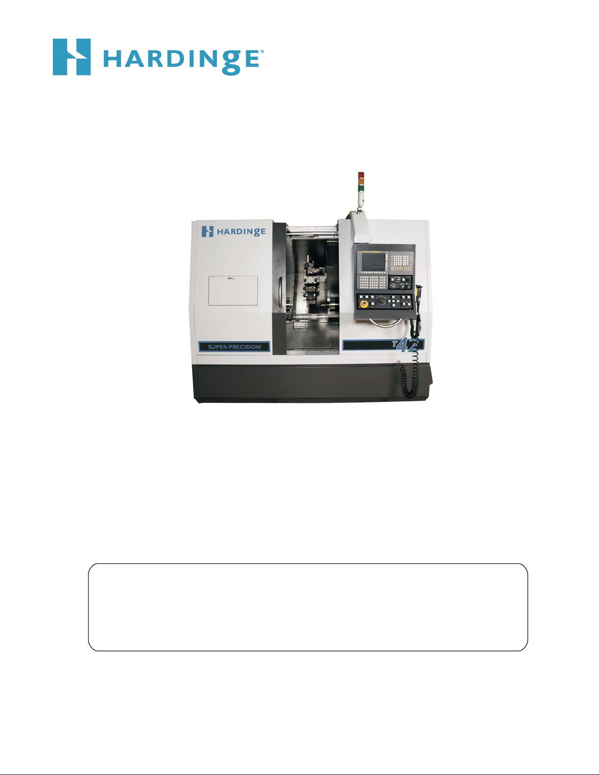
MACHINE DIMENSIONS
T-42 AND T-42 BIG-BORE LATHES
24.0
[610]
Minimum Recommended Space to Allow
Power Case Platform to be Moved to Perform
Service at the Back of the Machine.
101.4
[2576]
46.0
[1168]
Main Power Entrance
25.9
[658]
13.7 [348]
21.9
[557]
1.4 [35]
29.4
[747]
Provide Clearance for
Power Case Door Swing
Lift Slot
30.0
[762]
39.9
[1015]
Main Air Connection
(at bottom of platform)
Lift Slot
Adjustable Foot
Non-Adjustable Feet
72.6
[1844]
80.0
[2031]
98.0
[2488]
43.5
[1106]
Optional
Chip Conveyor
Note: Dimensions are Inches [Millimeters]
TI5696E
Figure 1.1 - Machine Dimensions and Support Feet Locations: T-42 Lathe
1-2 M-507C
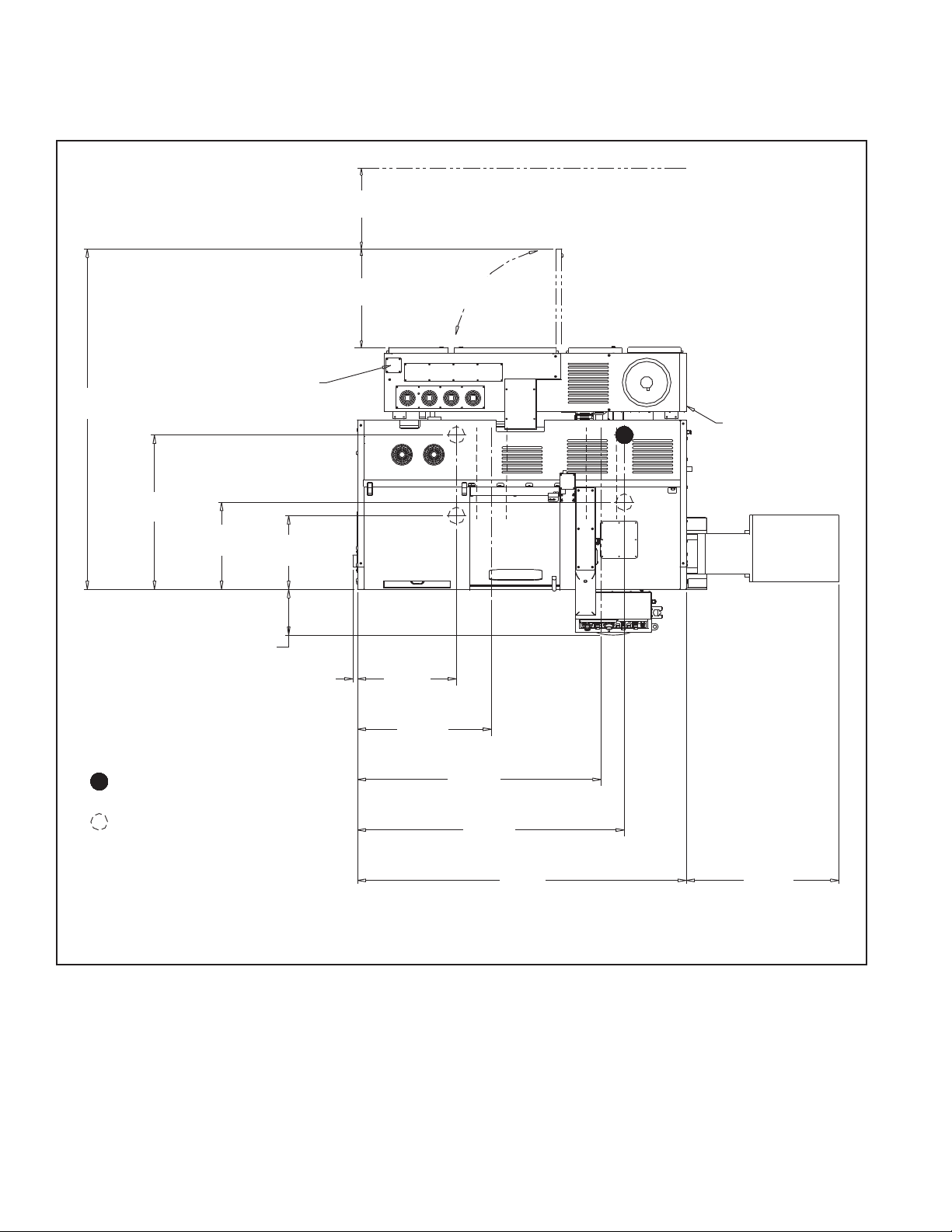
T-51 AND T-65 LATHES
Refer to Figure 1.2 for T-51 and T-65 lathes with serial numbers DQ-101 through
DQ-110, DQ-112, DQ-117, and DQ-120.
Refer to Figure 1.3 for T-51 and T-65 lathes with serial numbers DQ-111, DQ113
through DQ-116, DQ-118, DQ-119, DQ-121 and later.
Main Power Entrance
- NOTE -
Minimum Recommended Space to Allow
24.0
Power Case Platform to be Moved to Perform
[610]
Service at the Back of the Machine.
Provide Clearance for
32.3
[820]
Door Swing
109.9
[2791]
51.4
[1304]
Adjustable Foot
Non-Adjustable Feet
28.4
[723]
13.4 [341]
24.2
[615]
36.5
[927]
[1151]
45.3
77.3
[1964]
85.3
[2167]
Lift Slot
128.2
[3257]
Main Air
Connection
(at bottom of
platform)
Lift Slot
43.2
[1097]
Optional
Chip Conveyor
Note: Dimensions are Inches [Millimeters]
TI5850
Figure 1.2 - Machine Dimensions and Support Feet Locations: T-51 and T-65 Lathes
(Machine Serial Numbers DQ-101 through DQ-110, DQ-112, DQ-117, and DQ-120)
M-507C 1-3
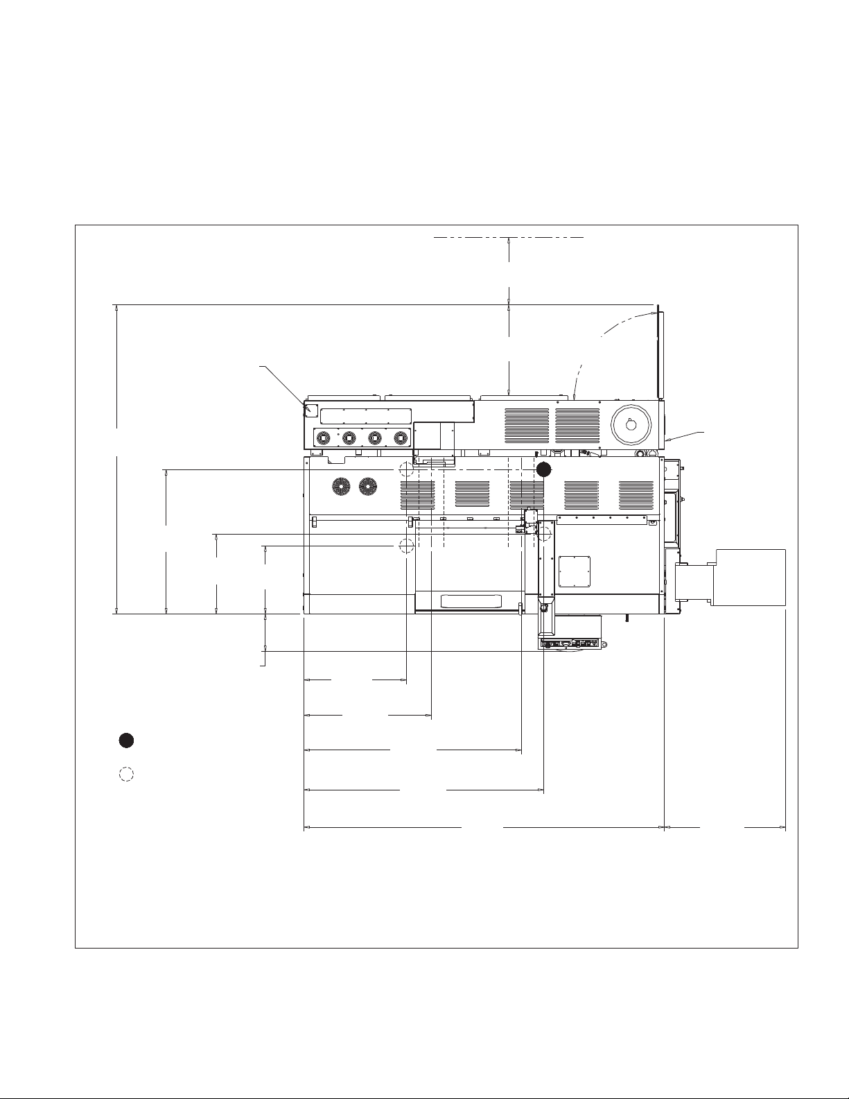
Main Power Entrance
Minimum Recommended Space to Allow
24.0
Power Case Platform to be Moved to Perform
[610]
Service at the Back of the Machine.
Provide Clearance for
32.3
[820]
Door Swing
109.9
[2791]
51.4
[1304]
Adjustable Foot
Non-Adjustable Feet
28.4
[723]
13.4 [341]
24.2
[615]
36.5
[927]
[1151]
45.3
77.3
[1964]
85.3
[2167]
Lift Slot
93.3
[2370]
Main Air
Connection
(at bottom of
platform)
Lift Slot
128.2
[3257]
Note: Dimensions are Inches [Millimeters]
43.2
[1097]
Optional
Chip Conveyor
TI5886
Figure 1.3 - Machine Dimensions and Support Feet Locations: T-51 and T-65 Lathes
(Machine Serial Numbers DQ-111, DQ113 through DQ-116, DQ-118, DQ-119, DQ-121 and Later)
1-4 M-507C

SETTING THE MACHINE
- NOTE -
Review the machine installation requirements on page 1-1 before beginning the
installation.
1. Verify that the foundation for the machine meets the requirements, as outlined on page 1-1.
2. Leave the machine on the skid and move it to the installation location.
3. Remove any parts boxes from the skid.
- NOTE -
Retain the M12 screws, washers, lock washers, and hold-down brackets in the
event the machine is to be used with a bar feed system. Refer to page 1-6 for
information on securing the machine to the floor.
4. Remove the M12 screws, washers, and lock washers that secure the hold-down brackets to the
machine.
5. Remove the hold-down brackets from the skid.
6. Thread the adjustable foot, shown in Figures 1.1 through 1.3, all the way up for clearance.
Initially, the machine is supported by the three non-adjustable feet.
- WARNING -
Raise the machine high enough to make certain that the machine feet and support screws clear the skid.
- NOTE -
There are two lift slots running front to rear under the machine base. Refer to
Figure 1.1, 1.2, or 1.3. Lift the machine slowly to make certain that the fork lift
truck maintains balance.
7. Use a fork lift truck or the rigging to lift the machine from the skid. Lift the machine slowly while
making certain that it remains balanced.
8. Carefully lower the machine into position. The machine will be supported by the three
non-adjustable feet. Rough align the machine.
9. Thread the adjustable foot down until it makes contact with the floor.
10. Tighten the adjustable foot an additional one-sixteenth turn.
11. Secure the adjustable foot lock nut up against the machine base.
M-507C 1-5
SECURING THE MACHINE TO THE FLOOR
- CAUTION -
The hold-down brackets MUST be installed if the machine is to be used with a bar
feed system.
- NOTE -
The lag screws, flat washers, and expansion shields used to secure the hold-down
brackets to the floor are provided with the machine
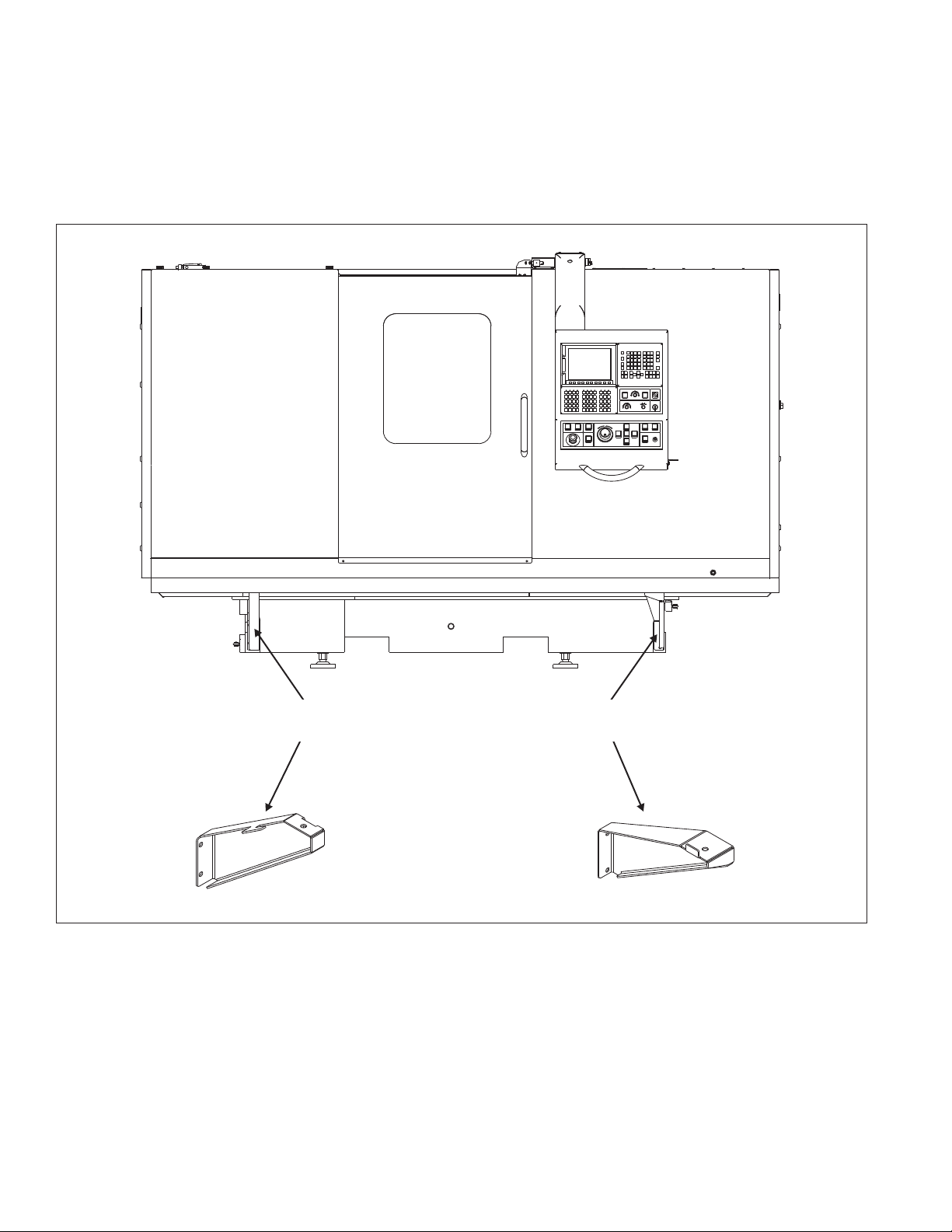
1. Align the hold-brackets with the mounting holes on the machine base. Refer to Figure 1.4.
2. Mark two drilling locations on the floor for each bracket.
3. Drill 3/4 inch [19 millimeter] diameter holes, 4 inches [102 millimeters] deep.
4. Remove any debris from the drilled holes.
Left End of Machine Right End of Machine
Hold-Down Brackets
TI5849
Figure 1.4 - Machine Hold-Down Brackets
(T-51 Machine Shown)
1-6 M-507C
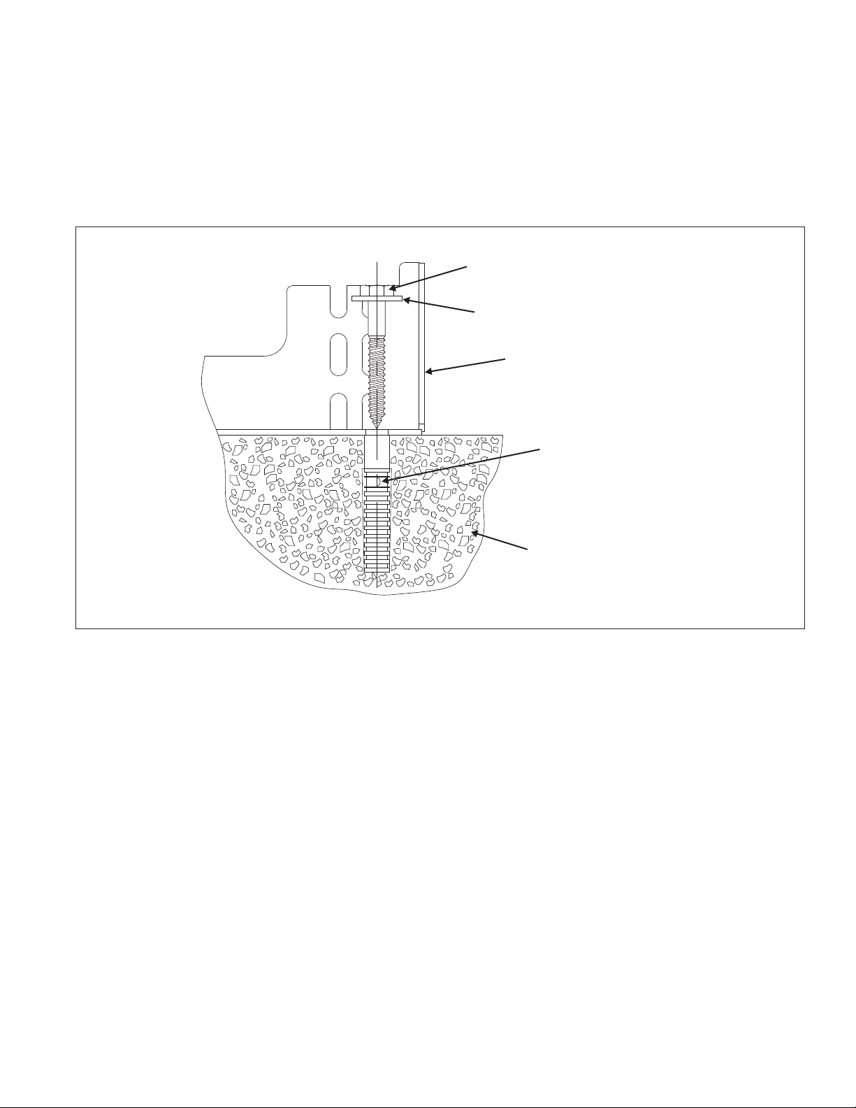
5. Drive an expansion shield down to the bottom of each hole. Refer to Figure 1.5.
6. Attach the brackets to the machine base using the M12 screws, washers, and lock washers
retained during the previous procedure.
7. Secure the brackets to the floor using the lag screws and flat washers provided.
Lag Screw
Flat Washer
Hold-Down Bracket
Expansion Shield
Concrete
Figure 1.5 - Expansion Shield and Lag Screw
TI5851
M-507C 1-7

DO NOT attempt to move the machine axes until the shipping brackets have been
removed.
The shipping brackets are painted RED for easy identification.
DO NOT discard the shipping brackets or mounting hardware. The brackets must
be installed whenever the machine is to be moved.
T-51 and T-65 lathes shipped in containers have the control pendant mounted at
the right end of the machine during shipment. Information on mounting the control
pendant in operating position begins on page 1-15.
SHIPPING BRACKET LOCATIONS
•
Control pendant (Refer to note above)
•
Guard door (T-51 and T-65 lathes only)
•
Left and right front corners of coolant guard (T-51 and T-65 lathes only)
•
Left end of power case platform (Viewed from back of machine)
SHIPPING BRACKETS
- CAUTION -
- NOTE -
•
Machine carriage
1-8 M-507C
REMOVING THE PENDANT SHIPPING BRACKET
1. Remove the screws connecting bracket "A", Figure 1.6, to the top of the machine.
2. Swing the control pendant out to access the screws holding the bracket to the pendant.
3. Remove the screws to release the bracket from the pendant.
4. Install all screws back in location to seal the holes.
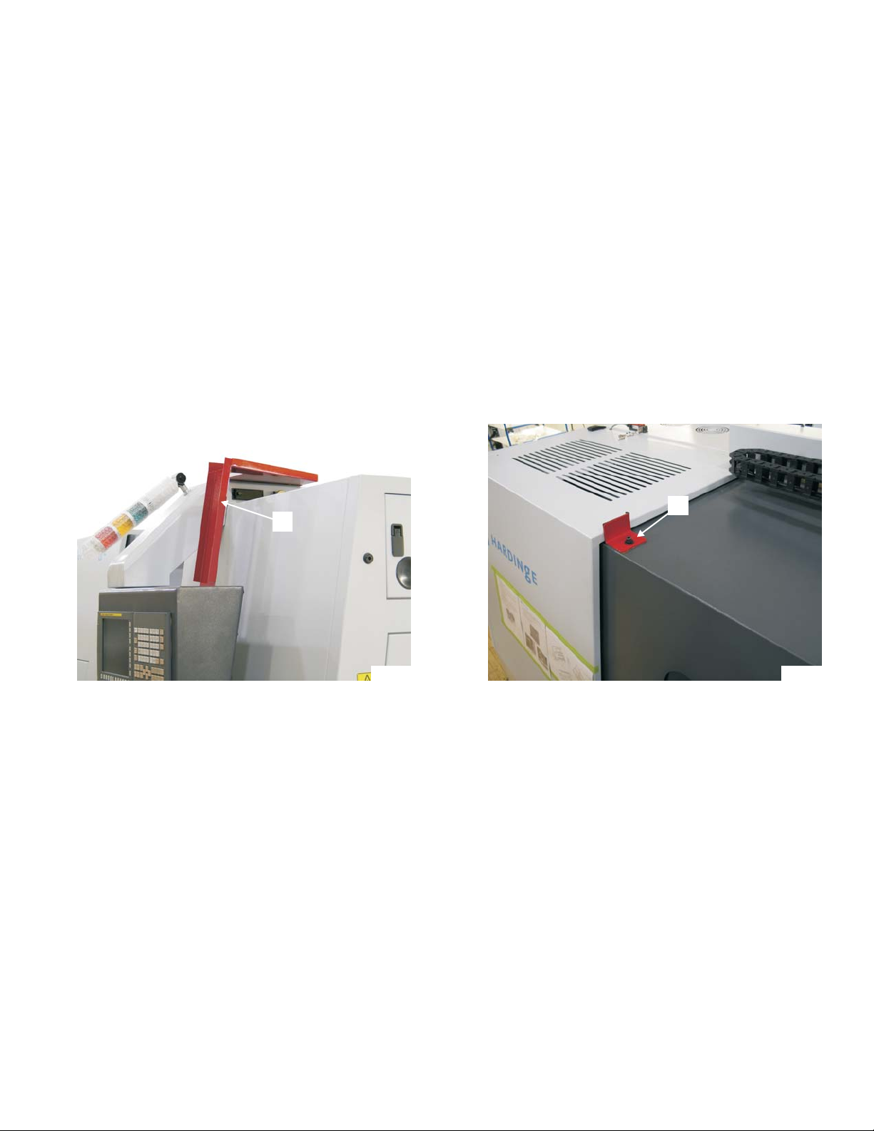
REMOVING THE GUARD DOOR SHIPPING BRACKET (T-51 AND T-65 LATHES)
Remove guard door shipping bracket "B", Figure 1.7.
A
Figure 1.6 - Control Pendant
Shipping Bracket
TP7955A
B
TP8319
Figure 1.7 - Guard Door Shipping Bracket
(T-51 and T-65 Lathes)
M-507C 1-9
REMOVING THE GUARD SUPPORT BRACKETS (T-51 AND T-65 LATHES)
Remove the left and right guard support brackets, shown in Figure 1.8.
Left Guard
Support Bracket
Isometric View
of Brackets
Right Guard
Support Bracket
TI5852
Figure 1.8 - Guard Support Brackets
(T-51 and T-65 Lathes)
1-10 M-507C
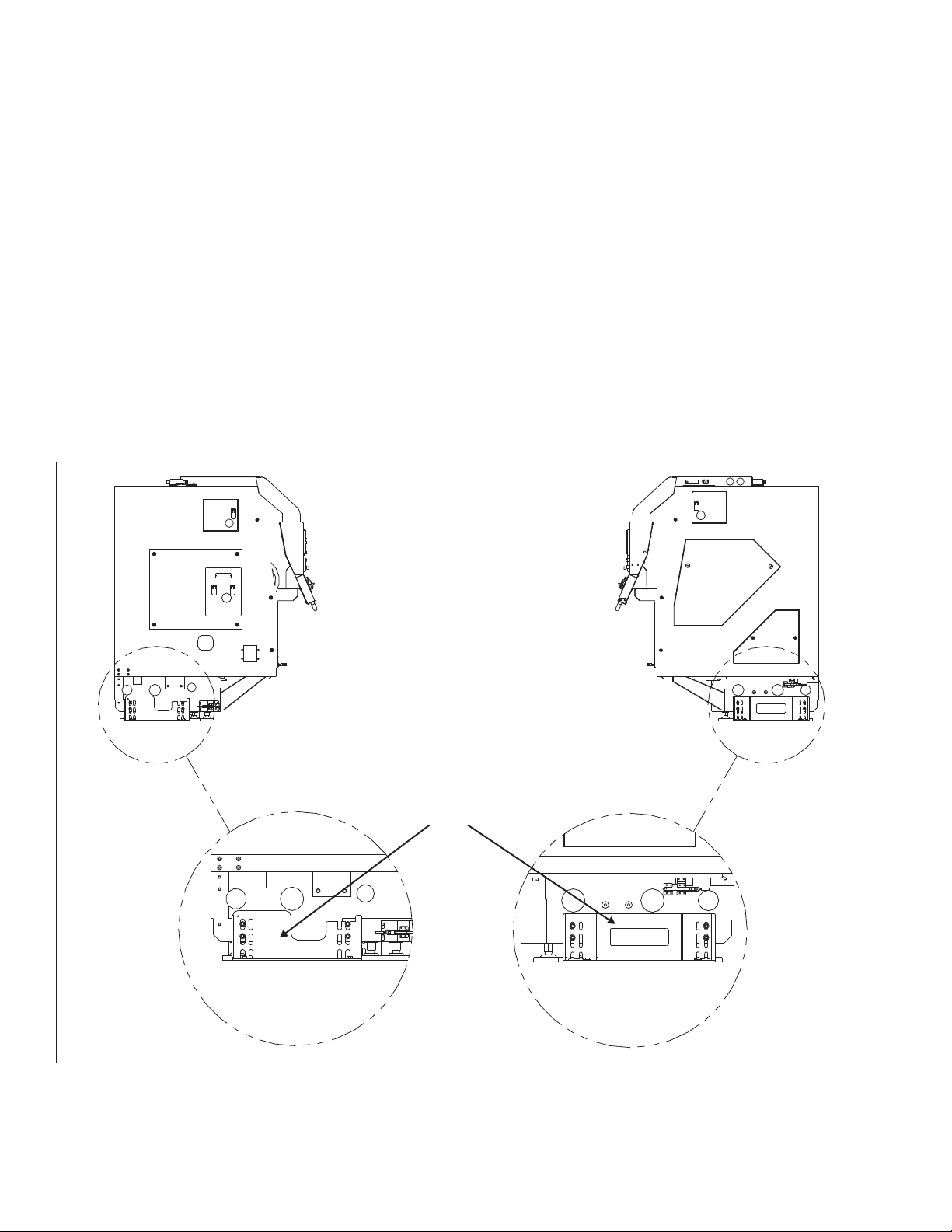
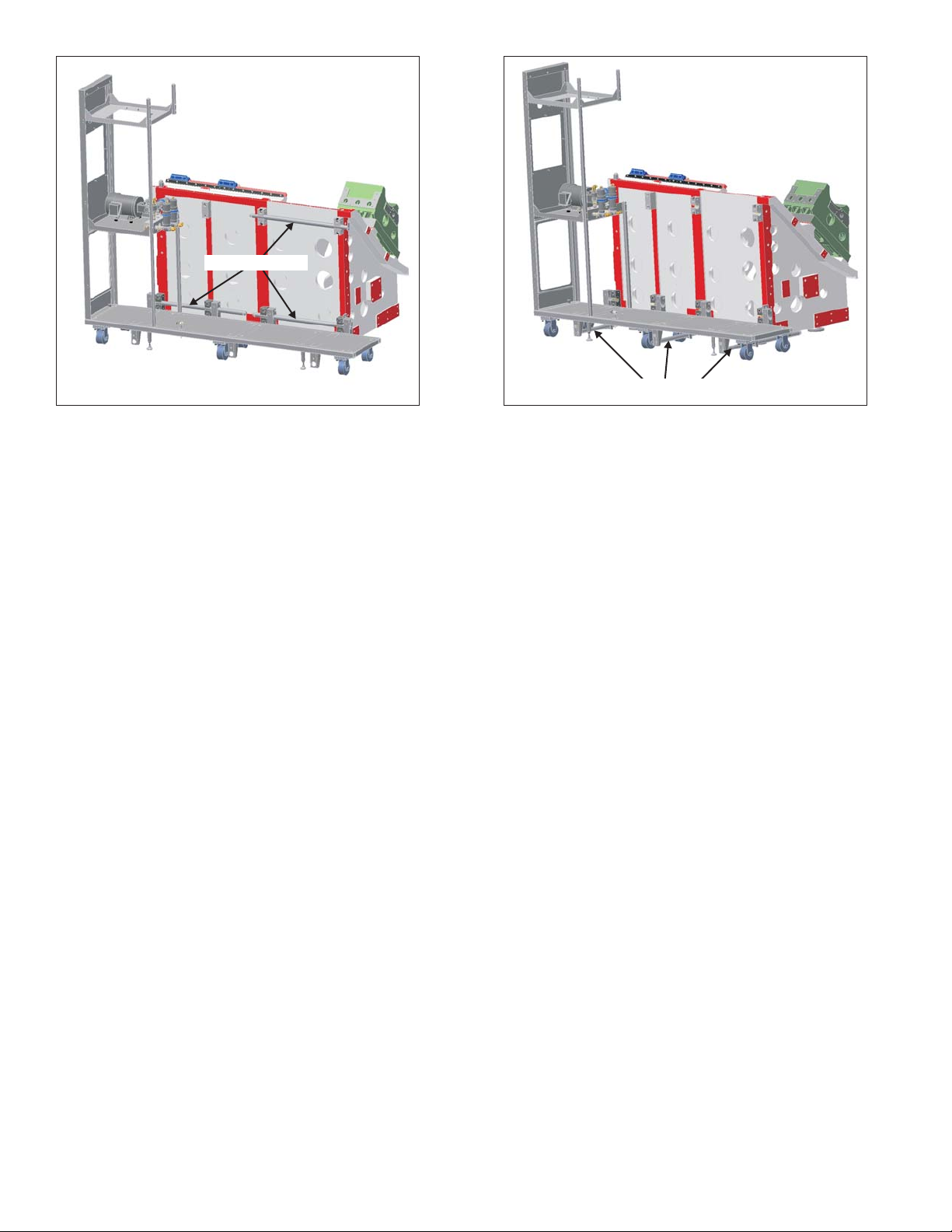
REMOVING THE PLATFORM AND CARRIAGE SHIPPING BRACKETS
1. Release latch "C", Figure 1.9, and open the
access doors.
2. Remove the nut and washer under the platform
to release the lower end of bracket “D”, Figure
1.10, from the platform.
3. Release the upper end of bracket "D" and
remove.
4. On T-51 and T-65 lathes:
A) Remove the nut and washer under the tray
to release the lower end of bracket “E”,
Figure 1.11, from the machine.
B) Release the upper end of bracket "E" and
remove.
Figure 1.9 - Hydraulic System
Access Doors
5. Remove carriage bracket "F", Figure 1.12.
C
TP7863
D
Figure 1.10 - Lower Power Case
Platform Shipping Bracket
F
TP7953
E
TP8328
Figure 1.11 - Upper Power Case
Platform Shipping Bracket
(T-51 and T-65 Lathes)
TP7954
Figure 1.12 - Carriage Shipping Bracket
M-507C 1-11

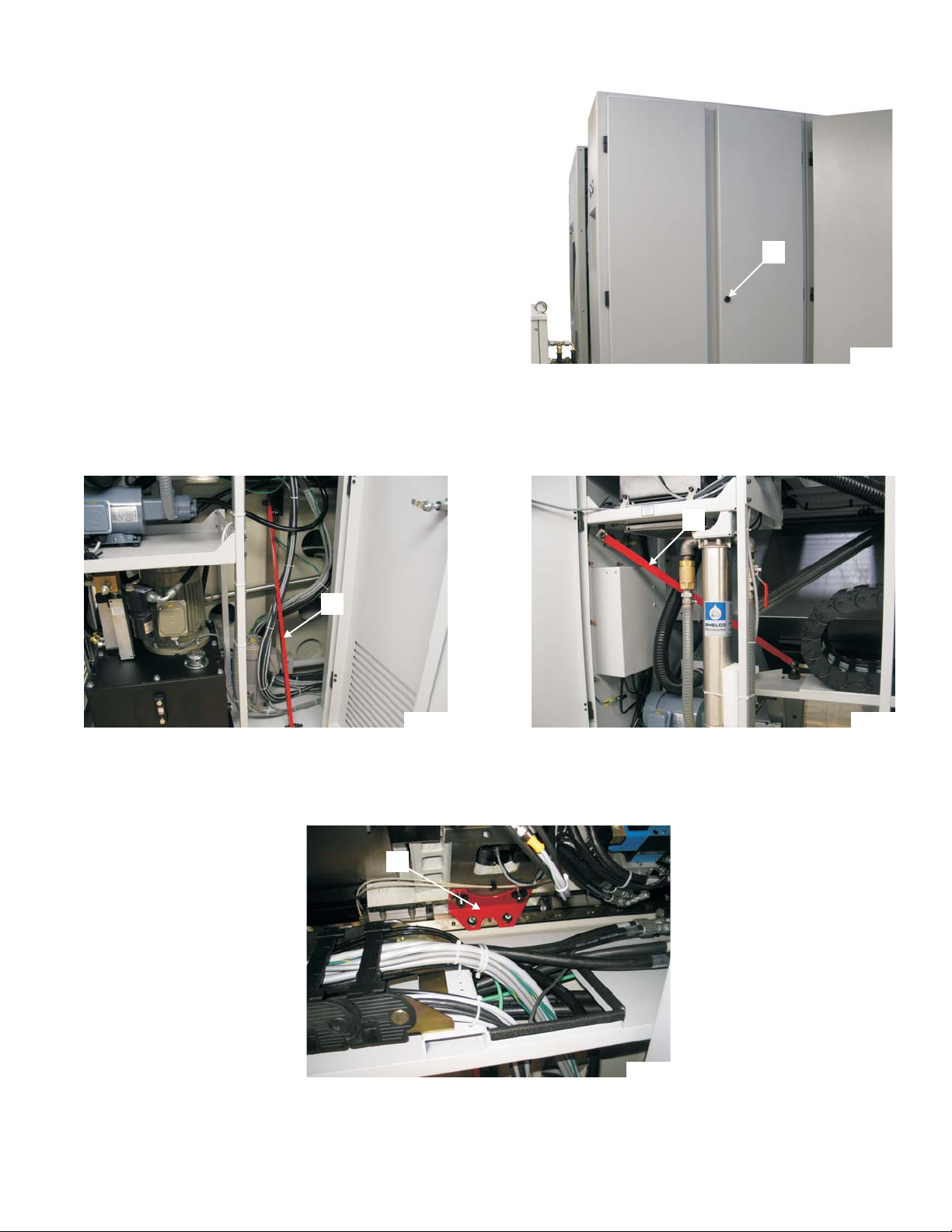
INSTALLING THE INTERLOCK SWITCH ON THE REAR ACCESS DOOR
For shipping purposes, the rear access door interlock switch is stowed next to the hydraulic unit
heat exchanger. Refer to Figure 1.13.
1. Using the fasteners supplied with the switch, mount the interlock switch on the access door, as
shown in Figure 1.14.
2. Close and latch the access doors.
Interlock Switch
Shipping Location
Figure 1.13 - Shipping Location
for Door Interlock Switch
TP8278
TP8279
Figure 1.14 - Interlock Switch
Mounted on Access Door
1-12 M-507C
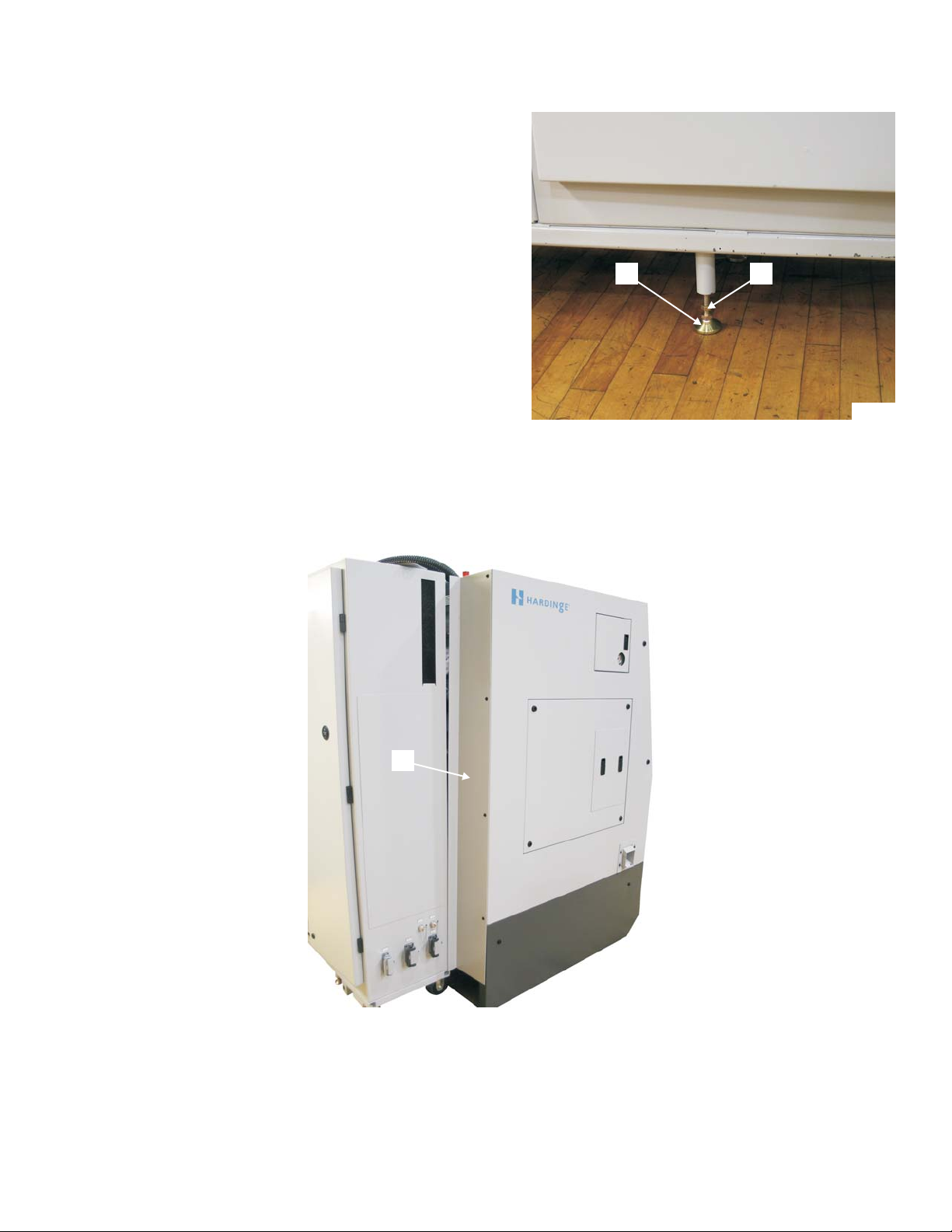
POWER CASE PLATFORM
- NOTE -
The power case platform is equipped
with two threaded platform legs.
1. Rotate two threaded platform legs “G”, Figure
1.15, downward until contact is made with the
floor.
2. Rotate the platform legs an additional ¼ turn.
3. Thread lock nuts "H" upward and tighten to
secure the platform legs.
4. Remove left end cover "I", Figure 1.16.
G H
TP7872
Figure 1.15 - Power Case Platform Legs
I
TP7956
Figure 1.16 - Left End Cover
M-507C 1-13
Shipping Tubes
Shipping Tubes
TP7941
Figure 1.17 - Shipping Tubes
Attached to Machine Pedestal
TP7940
Figure 1.18 - Shipping Tubes
Under Power Case Platform
(Components Removed for Clarity)
5. Remove the retaining screws from the three shipping tubes, shown in Figure 1.17.
- NOTE -
The shipping tubes are equipped with M8 threaded holes. If necessary, a threaded
rod can be used to remove the shipping tubes.
6. Remove the shipping tubes to disconnect the power case platform from the machine. Refer to
Figure 1.17.
7. Install the shipping tubes under the power case platform as shown in Figure 1.18.
8. Secure the shipping tubes with the retaining screws removed in step 5.
9. Install left end cover "I", Figure 1.16.
1-14 M-507C
MOUNTING THE CONTROL PENDANT IN OPERATING POSITION
- NOTE -
T-51 and T-65 lathes shipped in containers have the control pendant mounted at
the right end of the machine during shipment.
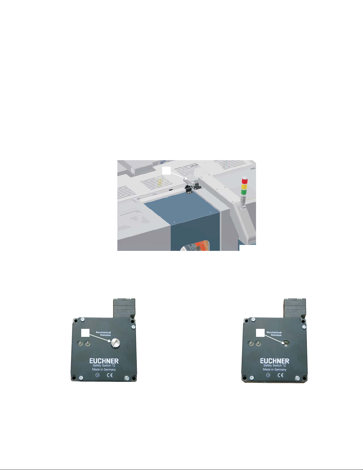
Door lock “J”, Figure 1.19, is located on the top of the machine.
1. Manually release the guard door lock:
A) Remove cap screw “K”, Figure 1.20, from the door lock.
B) Using the key attached to the door lock or a large flat blade screwdriver, rotate manual
release “L”, Figure 1.21, clockwise to allow the guard door to be opened.
2. Open the guard door.
J
Figure 1.19 - Door Lock Location
K
Figure 1.20 - Cap Screw
on the Door Lock
TP8031
TP7995
L
TP8032
Figure 1.21 - Door Lock
Mechanical Release
M-507C 1-15
3. Replace the cap screw on the door lock.
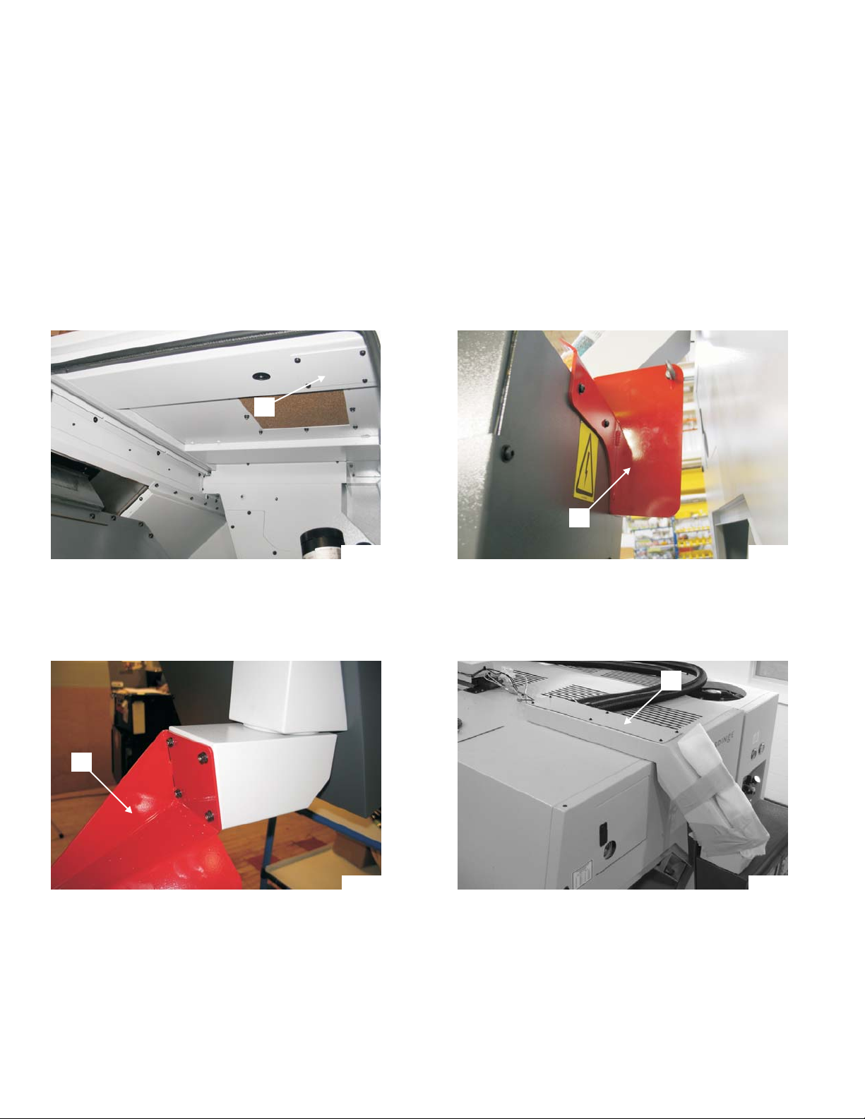
4. Remove access cover “M”, Figure 1.22.
5. At the right end of the machine, attach a hoist with lifting strap to the eyebolt on lifting bracket
“N”, Figure 1.23.
6. Apply tension to the lifting strap to support the pendant and wireway when the fasteners are
removed.
7. Remove the four flange nuts from lower pendant shipping bracket “O”, Figure 1.24.
8. Remove wireway top cover “P”, Figure 1.25.
M
Figure 1.22 - Access Cover
O
Figure 1.24 - Lower Pendant
Shipping Bracket
TP8376
TP8347
N
TP8346
Figure 1.23 - Pendant Lifting Bracket
P
TP8377
Figure 1.25 - Pendant Wireway
1-16 M-507C
Lower Front
Attachment Points
Upper Front
Attachment Points
TP8353
Figure 1.26 - Lower Front Attachment Point
Figure 1.27 - Upper Front Attachment Point
TP8349
9. Remove the eight screws that secure the wireway to the machine.
10. Carefully lift the pendant and wireway.
11. Rotate the pendant to the operating position at the front of the machine. DO NOT set into
position at this time.
12. Connect cable 3009.
13. If the machine is equipped with the optional part present detector, connect cable 5739.
14. Feed any excess wires and cables into the machine wire duct.
15. Apply a bead of silicone sealant around the lower front attachment points, shown in Figure 1.26.
16. Guiding the threaded stuns on the pendant into the upper and lower front attachment points,
Figures 1.26 and 1.27, set the pendant into position.
17. Inside the machine, install two flange nuts at the upper front attachment points.
18. Inside the machine, install four flange nuts at
the lower front attachment points.
19. Install access cover "M", Figure 1.22.
20. At the top of the machine, install the eight
screws to secure the wireway to the machine.
21. Install the wireway top cover.
Q
22. Remove lifting bracket “N”, Figure 1.23, from
the back of the pendant.
23. Remove lower shipping bracket “O”, Figure
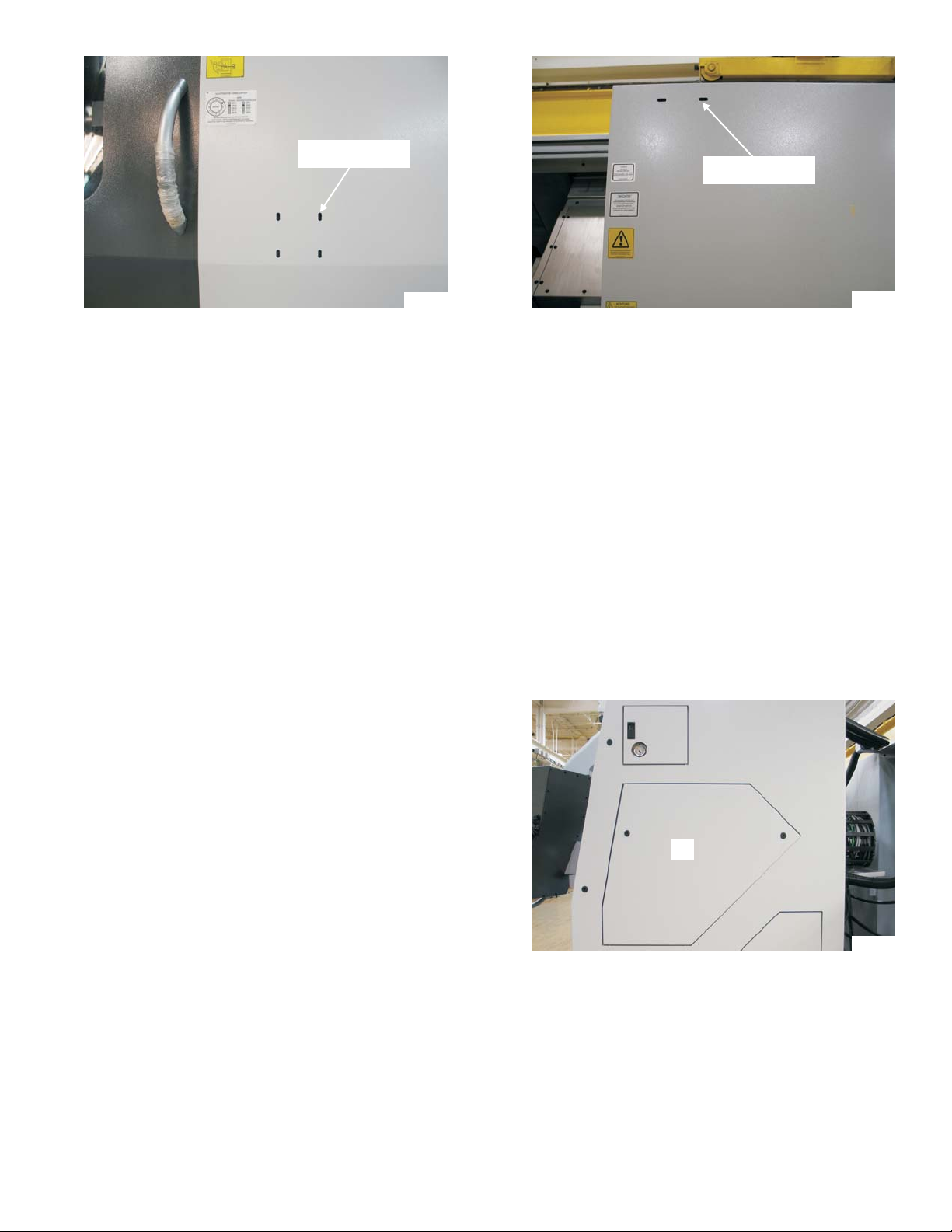
1.24, from the right end of the machine.
24. Install right end access cover "Q", Figure 1.28,
Figure 1.28 - Right End Access Cover
TP7961
on the machine.
M-507C 1-17

CLEANING THE MACHINE
- CAUTION -
Do not use compressed air to clean the machine. Air pressure forces dirt and
other foreign matter past the seals and covers into the slides, ball screws, and
bearings. This causes additional wear and will reduce the life and accuracy of the
machine.
After the machine has been properly located, remove all shipping grease, oil, and dirt accumulated
in transit. USE A CLOTH OR BRUSH WITH A GOOD GRADE OF PETROLEUM BASE GREASE
SOLVENT TO CLEAN THE MACHINE.
Use Clorox 409
not use benzene, leaded gasoline, acetone or chlorinated solvents.
®
cleaner with a soft, clean, lint-free cloth to clean the guard door vision panel. Do
1-18 M-507C
 Loading...