

Hardinge SERIES I Installation Operation & Maintenance
INSTALLATION, OPERATION,
MAINTENANCE, AND PARTS LIST
SERIES I
MILLING MACHINES
Revised: August 29, 2005
Manual No. M-450 Litho in U.S.A.
Part No. M -0009500-0450 June, 2003
TP5260
CHAPTER 2 - OPERATION
HEAD CONTROLS
R
Q
A
B
C
D
E
G
F
P
O
N
M
L
H
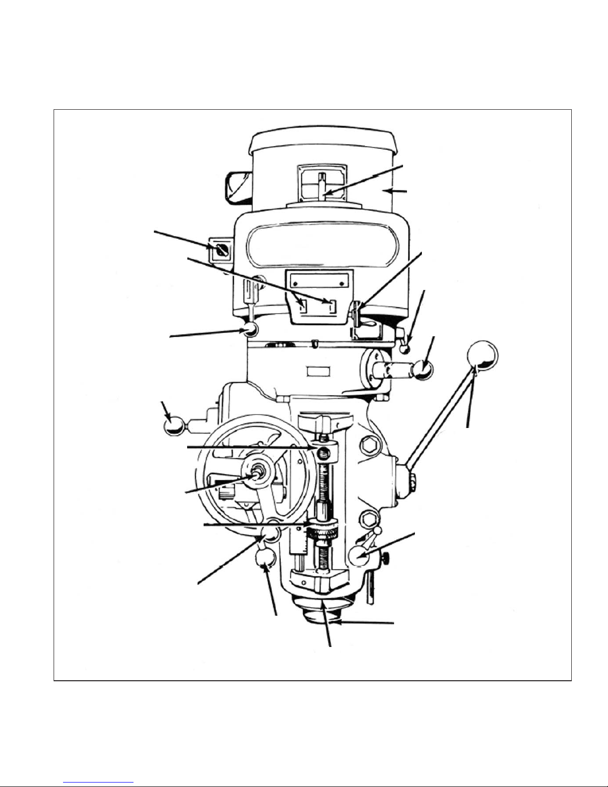
Figure 2.1 - Head Controls Parts Assembly
M-450 2-1
I
J
K
TP5285
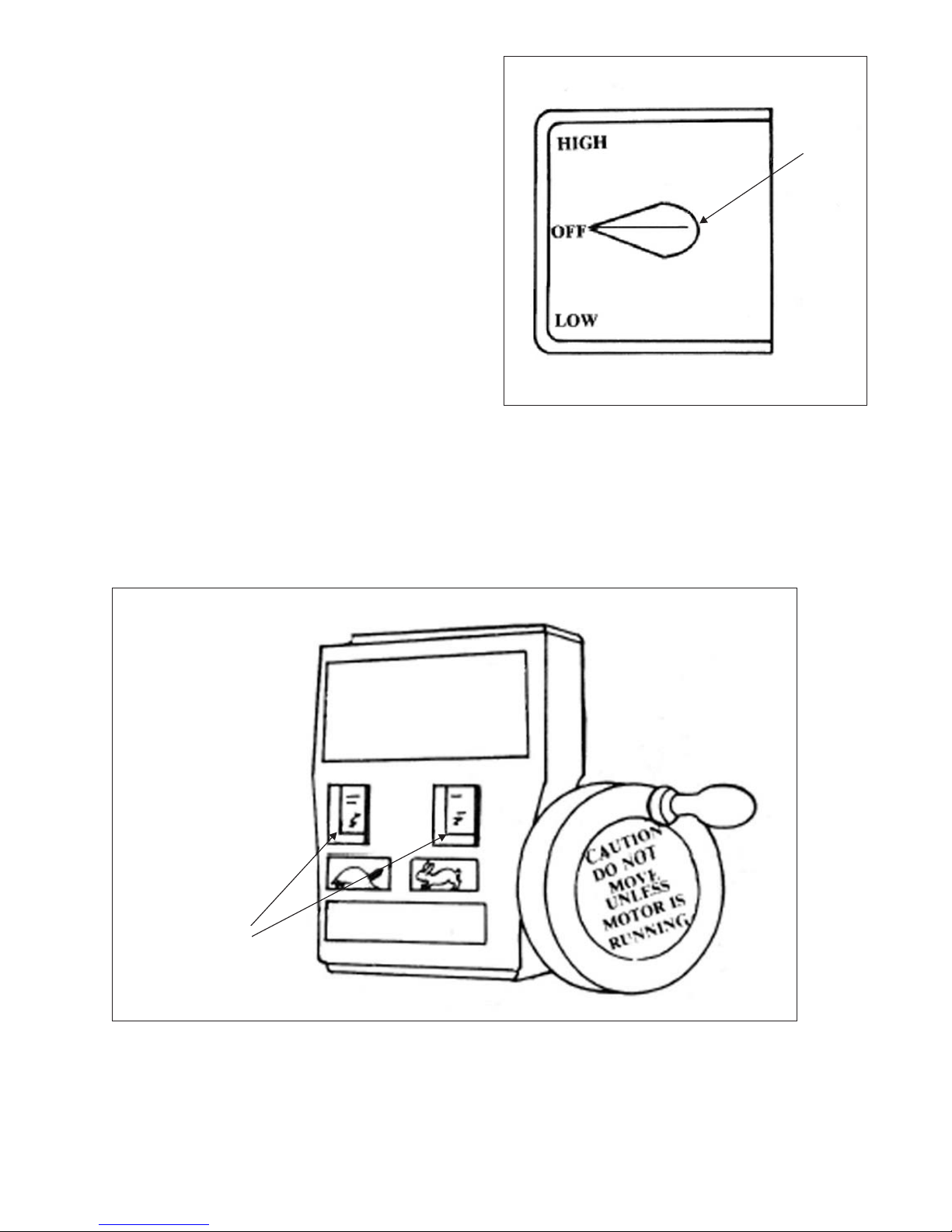
HIGH-LOW RANGE SWITCH
High-Low Range Switch “A”, Figure 2.2, is a
motor reversing switch. When the attachment is in
direct drive (HIGH SPEED), the motor and spindle
A
are turning in a clockwise direction as viewed from
the topof machine. When the attachment is in “Back
Gear”(LOW SPEED), the spindle willrunbackwards
(counter-clockwise) unless the motor direction is
reversed by moving switch to “Low”.
The back gear lever is marked Hi-Lo. This will
indicate the proper switch position. They should be
positioned alike or the spindle will run backwards.
- NOTE -
Spindle should run in clockwise position.
Figure 2.2 - High-Low Range Switch
VARIABLE SPEED DIAL
Variable Speed Dial “B”, Figure 2.3, visibly indicates, in windows, the speed range that the
machine is operating in, 60 to 500 low range, 500 to 4200 high range.
TP5286
B
Figure 2.3 - Variable Speed Dial
2-2 M-450
TP5287
SPINDLE BRAKE
Spindle Brake “C”, Figure 2.4, can be moved in
either direction to stop spindle; however, when
locking spindle, brake lever should be moved either
by pulling towards the operator or pushing away
from the operator, then raised. When brake is worn
out it has to be replaced. There are no adjustments
to be made.
- CAUTION -
BE certain that spindle brake is re
leased before starting the motor.
This is important as the motor can
be damaged if switch is turned on
with brake in locked position.
C
Lock On
Lock Off
TP5288
Figure 2.4 - Spindle Brake
QUILL FEED SELECTOR
The Quill Feed Selector “D”, Figure 2.5, is used
for selecting the three feeds: .0015”, .003” and .006”
per revolution. It is shifted by pulling knob out and
turning from one position to the other. Feeds are
stamped on cover below indentation hole. Feed is
more readily engaged when spindle is running.
D
TP5289
Figure 2.5 - Quill Feed Selector
M-450 2-3
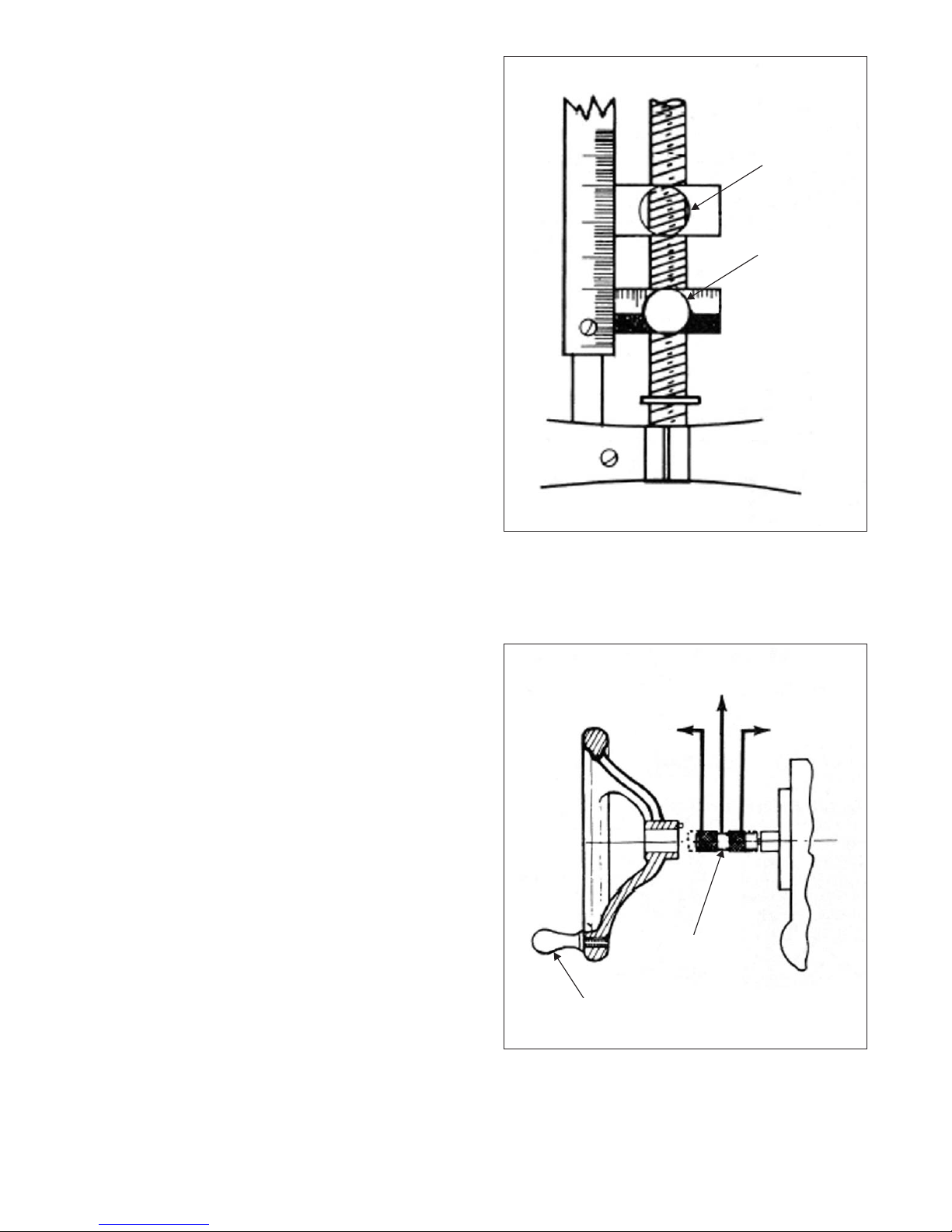
QUILL STOP KNOB
Quill Stop Knob “E”, Figure 2.6, is used to
disengage automatic feed in either direction as well
as the stop point setting working depths.
MICROMETER NUT
Micrometer Nut “F”, Figure 2.6, is used for setting
depths. Each graduation on nut indicates .001” of
depth, it reads directly to scale mounted along the
side of it. Depths may be obtained by setting
micrometer nut in conjunction with quill stop.
E
F
TP5290
FEED REVERSE KNOB
The position of the Feed Reverse Knob “G”,
Figure 2.7, depends upon direction of spindle
rotation. If boring with right hand cutting tools, pull
feed handle towards operator until clutch becomes
engaged.
Neutral position is between forward and reverse
position. It is recommended that the handle be left in
neutral position when not in use.
MANUAL FEED HANDWHEEL
Feed Reverse Knob “G” should be in neutral
position and Feed Control Lever “I”, Figure 2.8
engaged. Clockwise rotation of Manual Feed
Handwheel “H”, Figure 2.7, moves quill down. The
manual feed handwheel and the quill feed handle
may be disengaged by moving them outward about
.125”.
Figure 2.6 - Quill Stop Knob and
Micrometer Nut
Neutral
Up
G
H
Down
TP5291
2-4 M-450
Figure 2.7 - Feed Reverse Knob and
Manual Feed Handwheel
FEED CONTROL LEVER
Feed Control Lever “I”, Figure 2.8, engages
overload clutch on pinion shaft when positioned left
and will stay engaged until either quill stop comes in
contact with micrometer adjusting nut, forcing feed
control lever to drop out automatically, or release
manually by engaging lever to right.
FEED CONTROL OVERLOAD CLUTCH
The Feed Control Overload Clutch is set at the
factory to hold up to 200 lbs of down pressure on
quill, which will accommodate drills up to .375”
diameter in mild tool steel.
- CAUTION -
This clutch should not be tampered
with in the field.
Engage
I
Disengage
- NOTE -
The feed control lever must be en
gaged in order to use manual feed
controls. the quill feed handle and
manual feed handwheel may be
removed when not in use.
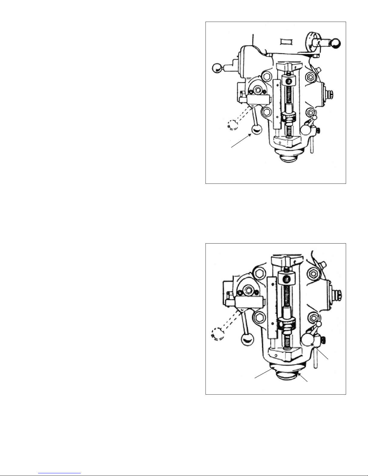
QUILL
Quill “J”, Figure 2.9, contains the spindle
assembly and can be raised or lowered by using the
quill feed handle “M”, Figure 2.10.
SPINDLE
Spindle “K”, Figure 2.9, performs the actual
rotation and also retains the machine tooling.
QUILL LOCK
Quill Lock “L”, Figure 2.9, is a friction lock for use
when quill isin a stationaryposition such as a milling
operation. It is recommended that this lock be used
whenever quill movement is not desired.
TP5292
Figure 2.8 - Feed Control Lever and
Feed Control Overload Clutch
J
K
TP5293
L
M-450 2-5
Figure 2.9 - Quill, Spindle and
Quill Lock
QUILL FEED HANDLE
Quill Feed Handle “M”, Figure 2.10, is used to
raise and lower the quill manually. It is generally
recommended that handle be engaged when using
the power feed. It may be removed by simply pulling
handle off.
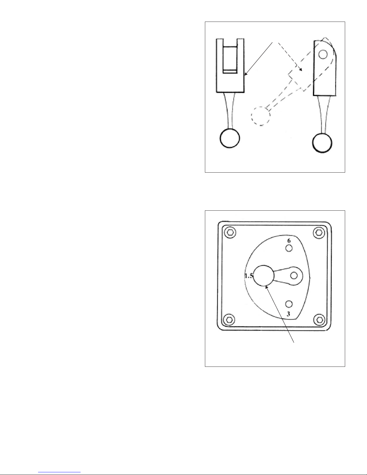
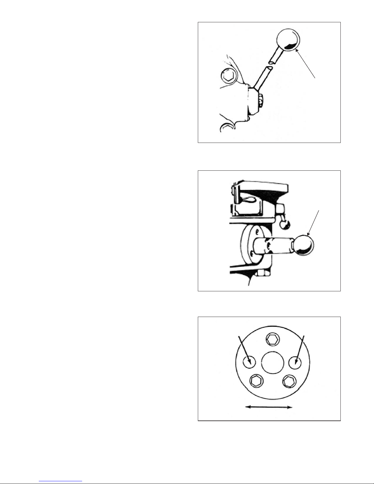
POWER FEED TRANSMISSION ENGAGEMENT
CRANK
M
TP5294
Figure 2.10 - Quill Feed Handle
Power Feed Transmission Engagement Crank
“N”, Figure 2.11, engages power feed worm gear.
When lever is in right hand hole, the power feed
worm gear is engaged.
To engage worm gear, pull knob out and crank
handle in clockwise or down direction and move to
opposite position (see Figure 2.12).
- NOTE -
Crank should be rotated counter-clockwise to engage power quill feed. Crank
should be rotated clockwise to disen
-
gage.
- CAUTION -
Power feed worm gear may be en
gaged when spindle is rotating,
however, it should be engaged
gently to avoid damage to worm
gear. The worm gear may be disen
gaged at any time. do not use power
feed at speeds above 3000 RPM.
N
TP5295
Figure 2.11 - Power Feed Transmission
Engagement Crank
Disengaged Engaged
2-6 M-450
Clockwise
CounterClockwise
TP5296
Figure 2.12 - Worm Gear Disengagement
 Loading...