

Page 1
INSTALLATION, OPERATION,
MAINTENANCE, AND PARTS LIST
SERIES I
MILLING MACHINES
TP8035
Revised: August 3, 2011
Manual No. M-508 Litho in U.S.A.
Part No. M -0009500-0508 June, 2010
Page 2

Information in this manual is subject to change without notice.
This manual covers installation, operation, maintenance, and parts list for
Bridgeport Series I milling machines with serial numbers ending with the let
ter "M". The machine serial number is located on the front of the knee. If the
machine serial number does not end with the letter "M", refer to the latest
version of manual M -0009500-0450.
In no event will Hardinge Inc. be responsible for indirect or consequential
damage resulting from the use or application of the information in this man
ual.
-
-
Reproduction of this manual, in whole or in part, without written permis
-
sion of Hardinge Inc. is prohibited.
ORDERING REPLACEMENT PARTS
Please provide the following information when ordering replacement parts:
1. The complete machine serial number. The machine serial number is located on the front of the
knee.
2. List the following:
A) Manual Number (M-508).
B) Page Number.
C) Item Number.
D) Part Description.
E) Part Number.
F) Quantity of each part required.
3. Specify how and where to ship.
- NOTICE -
Bridgeport is a registered trademark of Hardinge Inc.
© 2010, Hardinge Inc. M-508
Page 3

SAFETY
To prevent serious bodily injury, you should observe the following basic safety precautions when
installing, operating or servicing the milling machine.
1. Follow all instructions in the manual.
2. Wear approved industrial safety glasses and safety shoes.
3. Do not wear gloves, long sleeves, long hair, rings, watches, jewelry or other items that could
become caught in moving parts.
4. Keep all parts of your body away from moving parts (belts, cutters, gears, etc.)
5. Use proper point of operation safeguarding.
These and other safety precautions are discussed in the American National Standard Institute
standard entitled safety requirements for the construction, care, and use of drilling, milling, and
boring machines (ANSI B11-8-1983).
This publication is available from:
American National Standards Institute
25 West 43rd Street, 4th floor
New York, NY 10036
Safeguarding for protection at the point of operation can only be designed and constructed when
the parameters of the particular operation have been determined. As a result, ANSI B11.8-1983,
Section 5.1, states that “it shall be the responsibility of the employer to provide, and ensure use of, a
guard, guarding device, awareness barrier, awareness device, or shield…”
To assist machine users in designing point of operation safeguarding for their specific machine
applications, the Occupational Safety And Health Administration has published a booklet entitled
Concepts and Techniques of Machine Safeguarding (OSHA Publication No. 3067).
This publication is available from:
The Publication Office – OSHA
U.S. Department of Labor
200 Constitution Avenue, NW
Washington, D.C. 20210
The general purpose point of operation shield provided with this machine and shown in certain
illustrations throughout this manual may not be appropriate and cannot be utilized for all possible
applications of the machine. Use additional or alternate safeguarding where this shield is not
appropriate or cannot be utilized. Note that for purposes of display, the shield has been removed in
certain other illustrations in this manual.
M-508 i
Page 4

WARNINGS, CAUTIONS, AND NOTES
- WARNING -
Warning notices are used in this publication to emphasize that hazardous
mechanical conditions, voltages, currents, or temperatures exist in this
equipment which could cause serious personal injury and/or damage to the
equipment.
- CAUTION -
Caution notices are used where equipment might be damaged if care is not
taken.
In situations where inattention could cause either personal injury or damage to the equipment, a
warning notice is used.
- NOTE -
Notes merely call attention to information that is especially significant in under
standing and operating the equipment.
This document is intended for the use of those who install, operate and maintain the milling
machine. Although reasonable care has been exercised in the preparation of this manual to make it
complete and accurate, this manual does not purport to cover all conceivable problems or
applications pertaining to this machine.
-
ii M-508
Page 5

SAFETY RECOMMENDATIONS
DO NOT OPERATE EQUIPMENT until you have read and understood the appropriate opera
tor and safety maintenance manuals.
DO NOT OPERATE EQUIPMENT until you have read and understood all machine and con
trol key signs.
DO NOT OPERATE EQUIPMENT for the first time without a qualified instructor. Consult your
supervisor when in doubt as to the correct way to perform an operation.
DO NOT OPERATE EQUIPMENT unless proper maintenance has been regularly performed
and the equipment is known to be in good working order.
DO NOT ALLOW the operation or repair of equipment by untrained personnel.
WARNING or INSTRUCTION TAGS are mounted on the equipment for your safety and infor
mation. Do not remove them.
DO NOT OPERATE EQUIPMENT if any unusual or excessive heat, noise, smoke, or vibra
tion occurs. Report any excessive or unusual vibration, sounds, smoke, or heat as well as any
damaged parts.
WEAR SAFETY GLASSES with side shields and SAFETY SHOES with steel toes and oil-re
sistant soles at all times. When necessary, wear respirator, helmet, and ear muffs or plugs.
DO NOT OPERATE ANY MACHINE while wearing rings, watches, jewelry, loose clothing,
neckties, or long hair not contained by a net or shop cap.
-
-
-
-
-
DO NOT WEAR GLOVES while operating equipment. Gloves are easily caught in moving
parts.
REMOVE ANY LOOSE PARTS OR TOOLS left on machine or in the work area before operating the machine. Always check the machine and work area for loose tools and parts, especially after work has been completed by maintenance personnel.
REMOVE CHUCK WRENCHES before starting the machine.
NEVER OPERATE A MACHINE after taking strong medication, using non-prescription drugs
or consuming alcoholic beverages.
SAFEGUARD THE CUTTING ZONE (“point of operation”). Use standard, general purpose
safeguards when possible. Use special safeguards when required.
PROTECT YOUR HANDS. Stop the spindle completely before changing tools.
PROTECT YOUR HANDS. Stop the spindle completely before loading or unloading a
workpiece.
DO NOT REMOVE CHIPS with hands. Use a hook or similar device and make certain that all
machine movements have ceased.
DO NOT ADJUST tooling, workpieces or coolant hoses while the machine is running.
PROTECT YOUR HANDS. Stop the spindle completely before taking measurements.
PROTECT YOUR HANDS. Stop the spindle completely before opening safeguards or covers.
NEVER REACH around a safeguard.
M-508 iii
Page 6

PROTECT YOUR HANDS. Stop the machine before changing or adjusting belts, pulleys or
gears.
PROTECT YOUR HANDS. Keep hands and arms clear of spindle start switch when changing
tools.
PROTECT YOUR EYES AND THE MACHINE. Never use a compressed air hose to remove
chips.
KEEP WORK AREA WELL LIGHTED. ask for additional light if needed.
DON’T SLIP. Keep your work area clean and dry. Remove chips, oil and obstacles.
NEVER LEAN ON your machine. Stand away when the machine is running.
MAKE CERTAIN that you are clear of any “pinch points” created by moving slides before
starting the machine.
PREVENT OBJECTS from flying loose. Securely clamp and locate workpiece. Use stop
blocks where necessary. Keep clamps clear of cutter path.
PREVENT CUTTER BREAKAGE. Use correct table feed and spindle speed for the job. Re
duce feed and speed if you notice unusual noise or vibration.
PREVENT CUTTER BREAKAGE. Rotate spindle in clockwise direction for right-hand tools,
counterclockwise for left-hand tools. Use the correct tool for the job.
PREVENT WORKPIECE and cutter damage. Never start the machine when the cutter is in
contact with the workpiece.
DO NOT USE worn or defective tools. Use the proper size and type of tool for the task at
hand.
KEEP ROTATING CRANKS AND HANDWHEELS well lubricated and maintained. Do not re-
move safety springs.
CERTAIN MATERIALS, such as magnesium, are highly flammable in dust and chip form. See
your supervisor before working with these materials.
PREVENT FIRE. Keep flammable liquids and materials away from work area and hot chips.
PREVENT MACHINE from moving unexpectedly. Disengage power feed when not being used
(manual machines only).
PREVENT MACHINE from moving unexpectedly. Always start machine in manual mode.
UNLESS OTHERWISE NOTED, all operating and maintenance procedures are to be per
formed by one person. To avoid injury to yourself and others, be sure that all personnel are
clear of the machine when opening or closing the coolant guard door and any access covers.
-
-
iv M-508
Page 7

INSTALLATION AND USE OF SAFEGUARDS
Both American National Standard B11.8 and OSHA Section 1910.212 assign responsibility for
point of operation safeguarding of milling machines to the employer/user. Therefore, to prevent
serious injury resulting from the rotating cutter, flying chips, or splashing coolant, point of operation
safeguarding should be used on milling machines to the greatest extent practicable.
This booklet provides basic information for the installation and use of the general purpose
safeguard. It also contains the names of several manufacturers of other types of point of operation
safeguarding for vertical milling machines.
Remember, point of operation safeguarding is your responsibility as the employer/user. You are in
the best position to evaluate your safeguarding needs and ensure that the proper safeguards are
installed and used.
- CAUTION -
A safety shield is supplied for protection from chips and coolant with every
machine.
The chip and coolant shields have been designed and are custom manufac
tured with the highest clear impact material commercially available:
polycarbonate (G.E. Lexan). It has an impact strength 5 to 10 times greater
than acrylic (plexiglass) or butyrate (UVEX) materials, thereby offering the
greatest protection for our customers.
Some of the new “easy to dispose of” coolants and/or cutting oils contain
chemicals harmful to polycarbonate. These chemicals are:
Mono-ethanolamine, Di-ethanolamine, Tri-ethanolamine and the combination
thereof. These chemicals may significantly reduce the impact strength of the
shield within days, and could destroy the entire shield in weeks.
Use of use of coolants and/or cutting oils containing these chemicals will
void the warranty on your safety shield, and could cause injury to your workers.
- WARNING -
This safeguard DOES NOT take the place of any other safety practice or
safety equipment.
YOU MUST ALWAYS wear safety glasses and safety shoes.
YOU MUST ALWAYS stop the spindle of the machine completely before
changing or adjusting the workpiece, fixture, or tool.
-
YOU MUST NEVER wear gloves, long sleeves, long hair, rings, watches,
neckties, jewelry or other loose items.
M-508 v
Page 8
GENERAL PURPOSE SAFEGUARDS
There is no single safeguard which can match the versatility of the Series I machine. As a result,
you will find that the guard assembles shown in Figures I.I and I.II, like all safeguards, will be suitable
for some operations, but not for others. Carefully analyze the operation to be performed before
deciding whether this safeguard is suitable. Adjust the safeguard to suit your special requirements. If
you find that it is not suitable for a particular application, you should use an alternate form of
protection.
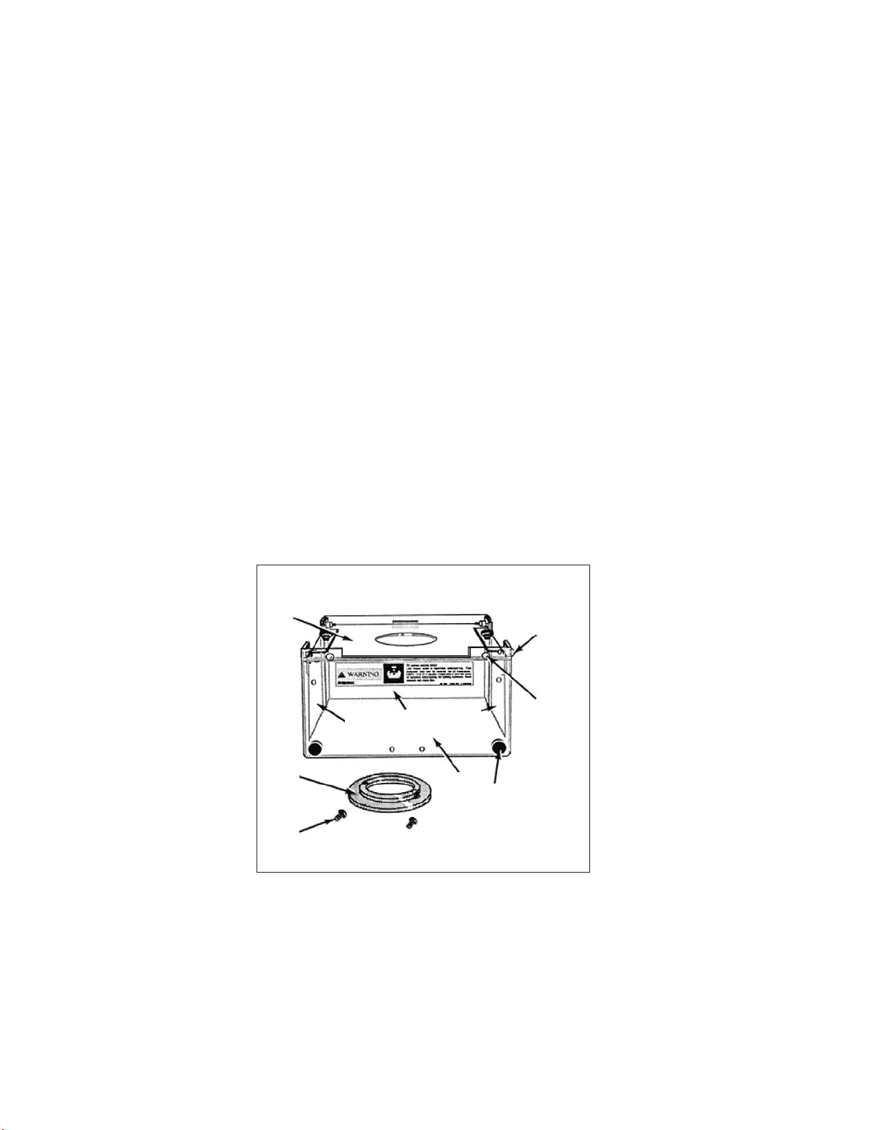
Installation for Machines with R-8 Spindle Taper
There are two tapped holes in the nose cap of the spindle to be used for mounting the guard (the
two untapped holes serve to remove the nose cap with a spanner wrench).
1. Place the mounting ring (Item 11) underneath the top of the guard (Item 7).
2. Place two socket head cap screws (Item 12) through the holes in the ring, and hand-start them
into the threaded holes in the nose cap until hand tight.
3. Align guard to be square with table of machine (unless angular mounting is desired).
4. Tighten screws with a hex Allen wrench.
7
6
9
2
11
12
10
1
Figure I.I - Spindle Guard Assembly
(R8 Spindle)
3,4,5
8
TP5262A
vi M-508
Page 9
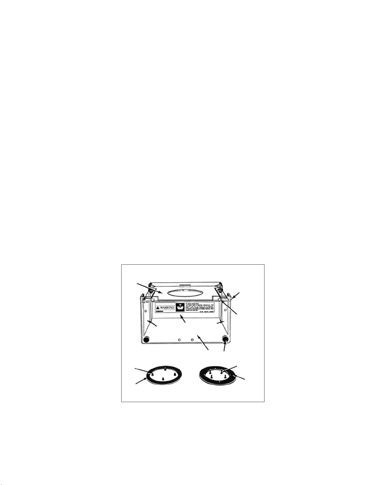
Installation for Machines with Erickson #30 Quick Change Spindles
1. Remove the spindle locknut. This is done by removing the long button head black finish screw,
which is normally left of the cadmium-finished button head screw on the locknut of the spindle.
This will allow you to unscrew the locknut by turning it counter-clockwise.
2. Place the nose cap mounting ring “O” up against the quill nose cap and install the four button
head cap screws “M”.
- NOTE -
The counterbored side of the nose cap mounting ring fits against the nose cap.
Observe the orientation of the mounting holes in the spindle and the mounting ring
to orient the quill guard as desired.
3. Place the mounting ring (Item 11) on the top of the guard (Item 7).
4. Place the locking ring (Item 12) underneath the top of the guard (Item 7).
5. Secure the two rings together with four #8-32 x 5/8 button head cap screws.
6. Lower the quill.
7. Position the guard under the spindle.
8. Use four #8-32 x 1/2 button head cap screws to secure the guard to the spindle.
9. Reinstall the quick change locknut. Refer to assembly instructions.
7
3,4,5
8
6
9
2
13
11
TP5263A
14
12
10
1
Figure I.II - Spindle Guard Assembly
M-508 vii
Page 10

Guard Assembly Component Lists
BP 11060813 – R-8 SHIELD ASSEMBLY
Refer to Figure I.I.
Item Part Number Description Qty
1 BP 11191203 Shield Assembly, Rear 1
2 BP 11010060 Screw, Hand 8-32 x .500 4
3 0300312 Screw, BHC 10-32 x .750 4
4 BP 11010065 Washer, Plastic #10-32 8
5 BP 11010055 Nut, Stop, #10-32 (Elastic) 4
6 BP 11060824 Shield, Right Side 1
7 BP 11060817 Shield Assembly, Top 1
8 BP 11010063 Screw, Drive, "Type U" #12 x .625 2
9 BP 11060820 Shield Assembly, Front 1
10 BP 11060822 Shield, Left Side 1
11 BP 11191201 Ring, Guard Mounting 1
12 0100610 Screw, SHC 1/4-20 x 5/8 2
BP 11060814 – QUICK CHANGE SHIELD ASSEMBLY
Refer to Figure I.II.
Item Part Number Description Qty
1 BP 11191203 Shield Assembly, Rear 1
2 BP 11010060 Screw, Hand 8-32 x .500 4
3 0300312 Screw, BHC 10-32 x .750 4
4 BP 11010065 Washer, Plastic #10-32 8
5 BP 11010055 Nut, Stop, #10-32 (Elastic) 4
6 BP 11060824 Shield, Right Side 1
7 BP 11060816 Shield Assembly, Top 1
8 BP 11010063 Screw, Drive, "Type U" #12 x .625 2
9 BP 11060820 Shield Assembly, Front 1
10 BP 11060822 Shield, Left Side 1
11 BP 12190330 Ring, Guard Mounting 1
12 BP 12190331 Ring, Guard Locking 1
13 0300208 Screw, BHC #8-32 x 1/2 4
14 0300210 Screw, BHC #8-32 x 5/8 4
viii M-508
Page 11

- NOTES -
M-508 ix
Page 12

- NOTES -
x M-508
Page 13

Table of Contents
CHAPTER 1 - INSTALLATION
Uncrating ....................................1-1
Shortages ....................................1-1
Cleaning ....................................1-1
Positioning the Head Upright ...........................1-2
Lifting the Machine................................1-4
Foundation ...................................1-5
Placing on a Solid Foundation .........................1-5
Leveling Bolts and Pads ..........................1-5
Machine Hold-Down Bolts .........................1-5
Leveling the Machine .............................1-6
Machine Power Supply..............................1-7
Connecting the Power Supply .........................1-7
Lubrication ...................................1-8
Alignment of the Head for Fine Work .......................1-9
CHAPTER 2 - OPERATION
Head Controls ..................................2-1
High-Low Range Switch............................2-2
Variable Speed Dial..............................2-2
Spindle Brake ................................2-3
Quill Feed Selector ..............................2-3
Quill Stop Knob ...............................2-4
Micrometer Nut ................................2-4
Feed Reverse Knob .............................2-4
Manual Feed Handwheel ...........................2-4
Feed Control Lever ..............................2-5
Feed Control Overload Clutch .........................2-5
Quill .....................................2-5
Spindle ...................................2-5
Quill Lock ..................................2-5
Quill Feed Handle .............................2-6
Power Feed Transmission Engagement Crank .................2-6
Hi-Neutral-Lo Lever ..............................2-7
Speed Change Handwheel ..........................2-8
Drawbar ...................................2-9
Operational Procedures ............................2-10
Spindle Speed ..............................2-10
Back Gear (Low Speed) ..........................2-10
Direct Drive (High Speed) .........................2-11
Quill Feed ................................2-11
Spindle Brake ...............................2-13
Quill Sensitive Hand Feed .........................2-13
M-508 xi
Page 14

Machine.....................................2-14
Operational Procedures ............................2-14
Swivel the Belt Housing ..........................2-14
Swivel the Turret .............................2-14
Move the Ram Slide ............................2-15
Saddle Clamping .............................2-15
Table Clamping ..............................2-16
Knee Clamping ..............................2-16
CHAPTER 3 - MAINTENANCE
2J-Head.....................................3-1
Motor Removal ................................3-1
Drive Belt Replacement ............................3-2
Timing Belt Replacement ...........................3-2
Brake Shoe Replacement ...........................3-3
Head ......................................3-4
Micro Feed Trip Assembly and Quill Removal .................3-4
Balance Spring Replacement .........................3-5
Feed Trip Adjustment .............................3-5
Collet Aligning Screw Replacement ......................3-6
Gib Adjustment .................................3-7
Adjustment of the Table Gib ..........................3-7
Adjustment of the Saddle Gib .........................3-8
Adjustment of the Knee Gib ..........................3-10
Table Feed Screw Backlash Adjustment......................3-12
Saddle Feed Screw Backlash Adjustment .....................3-13
CHAPTER 4 - PARTS LISTINGS
2J-Head
Top Housing .................................4-1
Back Gear ..................................4-4
2J- and J-Head Lower Housing ..........................4-7
Basic Machine ..................................4-12
Table and Lead Screw Assembly .........................4-15
Flood Coolant ..................................4-17
Lubrication System ...............................4-18
Replacement Motor Assemblies Available .....................4-19
Motor Assembly 2J-Head 2 HP Unified without NFPA, BP 12550150 .......4-19
Motor Assembly 2J-Head 2 HP Unified with NFPA ...............4-19
Motor Assembly 2J-Head 2 HP 575 Volts without NFPA, BP 12550020......4-20
Motor Assembly 2J-Head 2 HP 575 Volts with NFPA ..............4-20
Replacement Motors Available.........................4-20
2J Milling Head (1-1/2 HP) – Spare Parts ...................4-21
2J Milling Head (2 HP) – Spare Parts .....................4-21
Metric Conversion Kits ..............................4-21
BP 2184000 – 2J-Head, Metric Conversion Kit .................4-21
xii M-508
Page 15

CHAPTER 5 - SPECIFICATIONS
Machine.....................................5-1
Principle Dimensions .............................5-1
Left Side View of Machine .........................5-1
Top View of Machine ...........................5-2
Machine Specifications ............................5-3
2J-Head.....................................5-5
General Speed Recommendations .......................5-5
Table of Cutting Speeds and Feeds ......................5-5
M-508 xiii
Page 16

- NOTES -
xiv M-508
Page 17
CHAPTER 1 - INSTALLATION
UNCRATING
Carefully remove protective crating and skids so that the machine and parts are not marred,
scratched or impaired. In the event of damage having occurred during transit, communicate at once
with our representative and the transportation company making delivery.
SHORTAGES
Check shipment carefully against the itemized packing list which is included in the parts box. In
case of shortages, report them immediately to the representative from whom the machine was
purchased, indicating the parts not received which have been checked on the packing list.
CLEANING
Thoroughly clean protective coating from the machine with a suitable cleaning solution.
- WARNING -
DO NOT use gasoline or any other flammable cleaning agent to clean machine.
- NOTE -
Do not move the table, saddle, knee,
or any moveable part until all ways
have been well cleaned and lubricated.
1. After initial cleaning, move table, saddle and
knee in one direction by hand to limit stop.
2. Clean and lubricate the exposed ways.
3. Move each unit to the opposite limit stop, and
clean and lubricate the exposed ways.
4. Move each unit to the opposite stop once more
and similarly clean and lubricate the exposed
ways.
5. Loosen bolts to unlock the ram, and move it
forward and backward to the full length in order
to clean and lubricate.
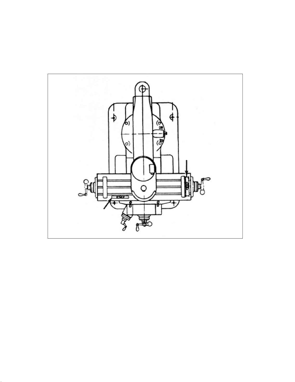
TP5277
Figure 1.1 - Milling Machine
Left Side View
M-508 1-1
Page 18
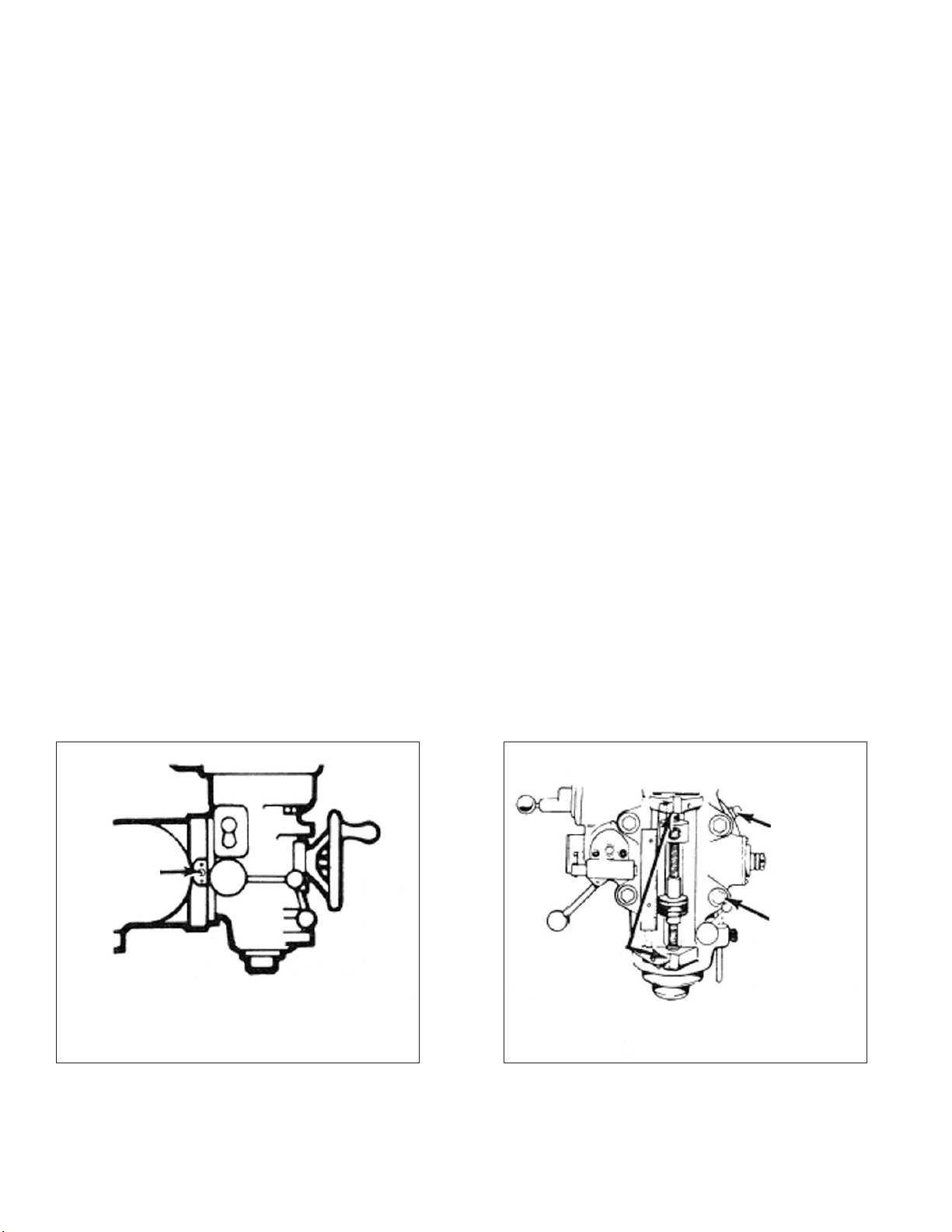
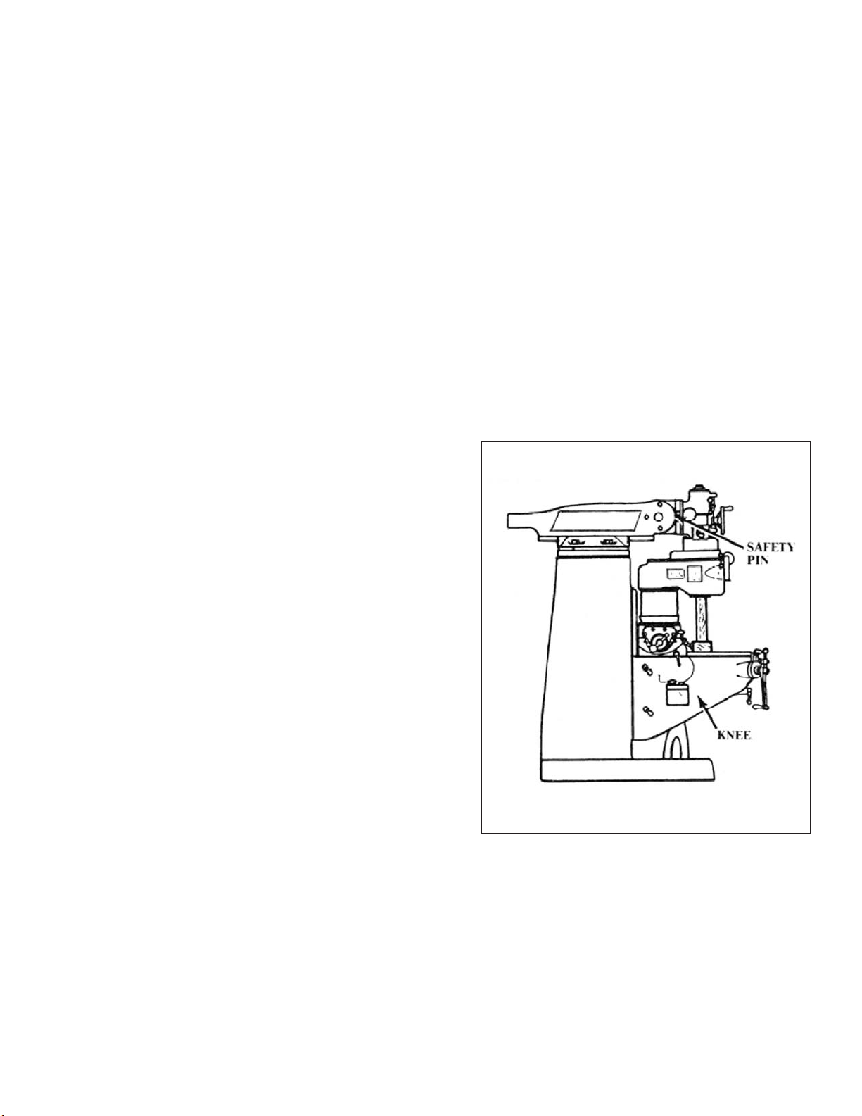
POSITIONING THE HEAD UPRIGHT
If delivery of your machine is made with the milling head in an upside-down position, follow the
instructions below to prepare your machine for operation.
For shipping purposes, the hand cranks are inverted to face the machine. To reverse them,
engage the lock mechanism to the saddle and table. Using a (1-inch) wrench, remove the retaining
lead screw nut and install the hand cranks properly.
Loosen four head mounting bolts “C”, Figure 1.3, and pull stop pin “A”, Figure 1.2, out to detent
and rotate head attachment using the swivel bolt “B”, Figure 1.3, in either direction until it has been
moved within approximately 20% of vertical. It is recommended supporting the head by hand to
relieve the weight on the swivel bolt, as a safety precaution, push the stop pin back in. Continue to
raise the head attachment to vertical position. Align the indicator on the head attachment with the
ZERO line on the ram adapter scale. Tighten all nuts first to 25 lb-ft torque in a diagonal sequence,
then to 50 ft/lbs.
- NOTE -
Care should be taken to avoid excessive pressure since this will cause distortion in
the quill.
1. Lower knee approximately 6” (150mm).
2. Withdraw the safety pin on the left-hand side of ram adapter.
3. Loosen the four unit head mounting bolts.
4. Support unit head manually and use a spanner on swivel bolt to wind into upright position.
5.
Press the safety pin back into the ram adapter after passing the 25° mark.
6. Tighten bolts first to 25 lb-ft torque in a diagonal sequence as noted in Figure 1.4, then to 50
lb-ft. Overtightening could cause bind in the quill movement.
B
A
C
Aligning
Faces
Swiveling Head
To Swivel the Head More Than 25°, the
Safety Pin “A” Must be Pulled Outwards
Figure 1.2 - Positioning Head
TP5278A
Figure 1.3 - Positioning Head
Left View
1-2 M-508
Table
TP5278B
Front View
Page 19
4
1
Figure 1.4 - Tightening Sequence
2
3
TP5280
M-508 1-3
Page 20
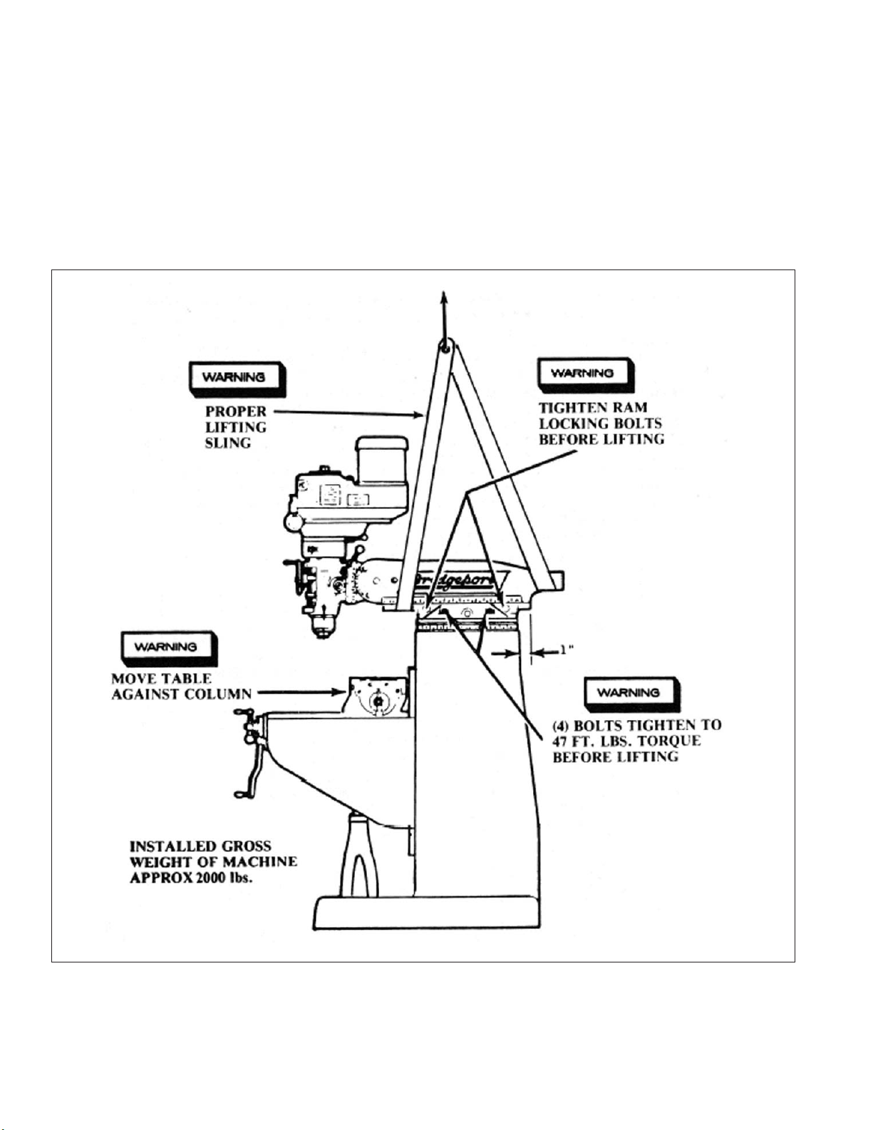
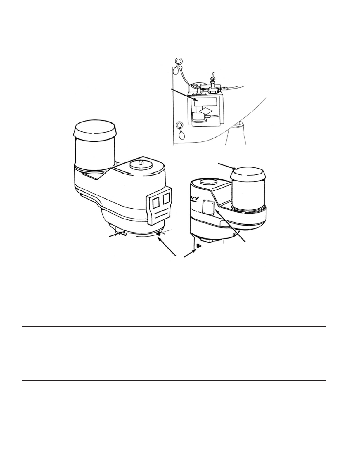
LIFTING THE MACHINE
- WARNING -
BE SURE to use proper sling when lifting. improper lifting could cause seri
ous injury.
Note position of ram and table when lifting with sling. Machine should be lifted by placing a sling
under the ram as illustrated in Figure 1.5.
-
TP5279
Figure 1.5 - Lifting the Machine
1-4 M-508
Page 21
FOUNDATION
PLACING ON A SOLID FOUNDATION
- NOTE -
It is recommended that the machine be secured to the floor to prevent movement
or tipping due to off-center loading. It is the customers responsibility to supply all
necessary hardware if the machine is to be secured to the floor.
When setting machine on a concrete foundation, it is advisable to use grout (thin
mortar) to take care of any unevenness in the concrete as well as to provide a
solid foundation at all points.
Leveling Bolts and Pads
The machine is supplied with leveling bolts and pads. Thread the bolts through the tapped holes in
the base and position on the machine on the pads. Refer to Figure 1.6. Level the machine as outlined
on the next page.
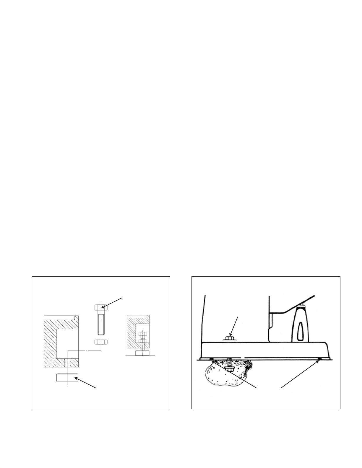
Machine Hold-Down Bolts
When setting machine on a floor than has any surface irregularities, shims should be used to
correct this condition to the greatest extent possible.
If securing machine to floor with hold-down bolts, make certain that all four corners are making
contact with the floor after machine is leveled. If above condition is not met, it is possible to twist the
column and put a bind into ways.
The machine should be placed on a solid level floor with shims or anti-vibration pads as shown in
Figure 1.7 to insure machine base is positioned evenly.
Leveling
Bolt
Hold-Down
Bolt
Leveling
Pad
Figure 1.6 - Leveling Bolts and Pads
M-508 1-5
TP8006
Figure 1.7 - Hold-Down Bolts
Shims
TP5281
Page 22
LEVELING THE MACHINE
Set machine by leveling the work table lengthwise and crosswise with a precision instrument as
shown in Figure 1.8.
Level
Level
Figure 1.8 - Leveling the Machine
TP5282
1-6 M-508
Page 23

MACHINE POWER SUPPLY
- WARNING -
Machine must be connected by a qualified electrician.
CONNECTING THE POWER SUPPLY
To connect the machine to the plant supply, have a qualified electrician proceed as follows:
1. Check required voltage against power supply to ensure that they are compatible.
2. Connect machine wiring to power supply making sure connection is in compliance with safety
regulations.
3. Check for correct spindle rotation. In the HIGH SPEED range, the spindle should rotate
clockwise when viewed from the top of the machine.
- NOTE -
Drum switch and Hi-Neutral-Lo lever must be in Hi range when checking spindle
rotation.
M-508 1-7
Page 24
LUBRICATION
1
3
4
Lubrication
Instruction Plate
2
Recommended Lubrication
Few Drops Twice Daily
Figure 1.9 - Lubrication Requirements
Indicator Lubrication Area Type of Lubrication
1 Way Surfaces and Lead Screws Sunoco Waylube #1180 or equivalent
2 Milling Heads (Spindle Bearings)
3 Motor None required. Motor greased for life of bearings
4
Not Shown Power Feed Oil to sight level with Mobilube No. 46 S.A.E. 140
Not Shown Shaping Attachment Mobil 600W Oil or equivalent
S.A.E. 10 or 10W Light Oil
(None on grease-packed heads)
Lubricate with grease every six months as described on
lubrication plate
TP5283
1-8 M-508
Page 25
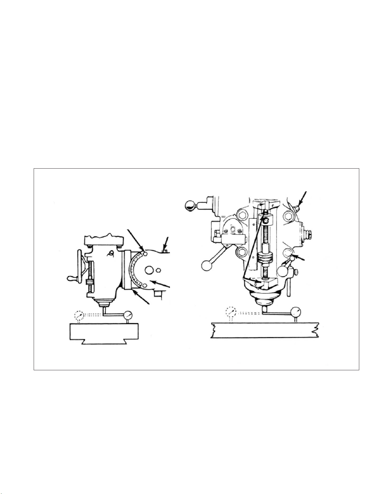
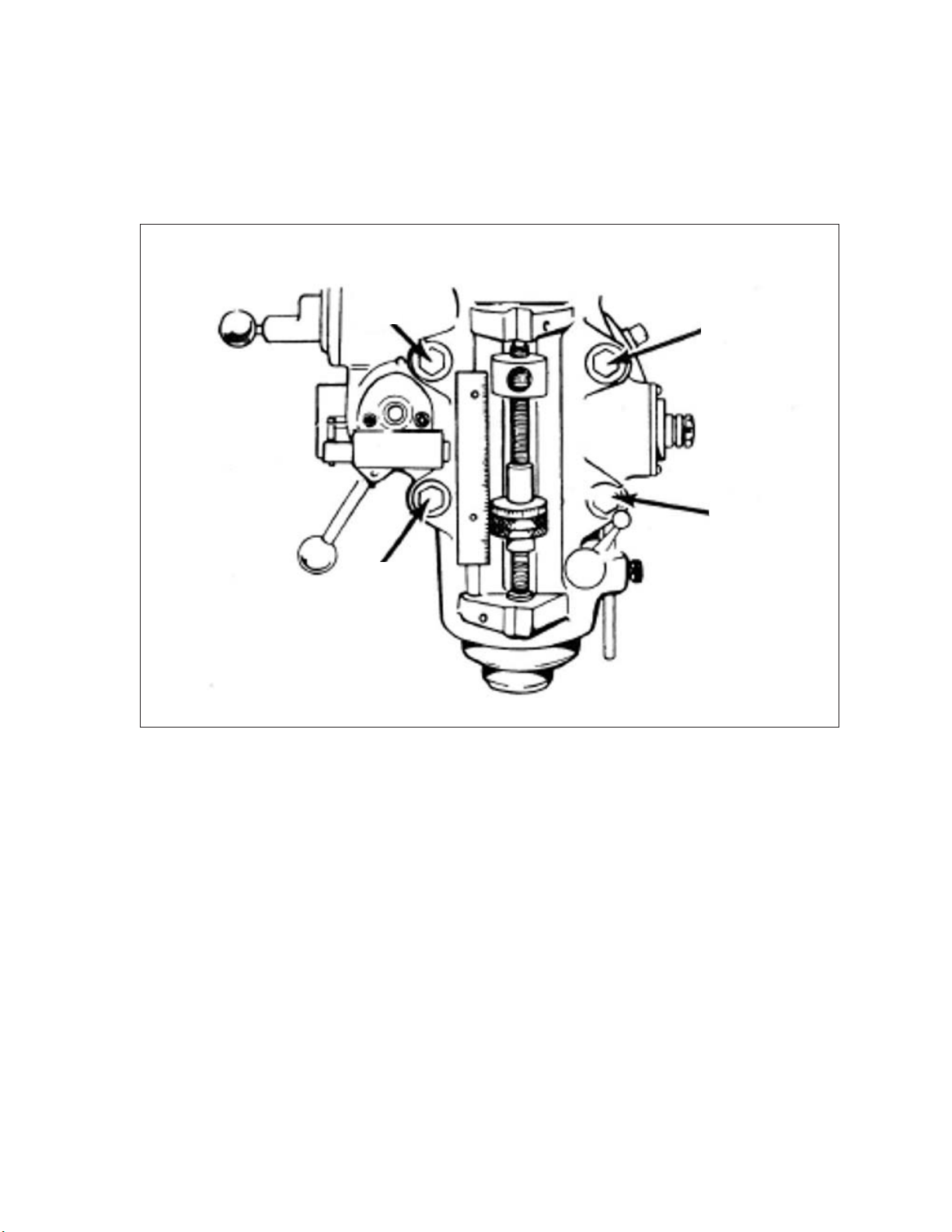
ALIGNMENT OF THE HEAD FOR FINE WORK
For precision boring or work of that nature, where it is necessary to have the head perfectly square
with the table, use method described below. To set head perfectly square with table, adjust ram
adapter through vertical adjusting worm shaft with ram adapter on ram. Loosen four locknuts but
leave drag on same for fine adjustment. To square head to table in the longitudinal axis, mount
indicator as shown in Figure 1.10. For general milling use, graduations provided on the head are
close enough.
Tighten the four head locknuts in a diagonal order as previously described on page 1-2. Tighten
the three ram locking bolts to 50 lb-ft.
- CAUTION -
Do not operate the machine until properly lubricated.
Adjustable
Worm Shaft
3 Ram
Locking Bolts
Zero
Head Alignment Y-Axis
Zero
Figure 1.10 - Head Alignment for Y and X Axis
Vertical Adjustable
Worm Shaft
Ram
Ram Adapter
Aligning
Faces
Zero
Head Alignment X-Axis
Locknuts
Zero
TP5284
M-508 1-9
Page 26

- NOTES -
1-10 M-508
Page 27
CHAPTER 2 - OPERATION
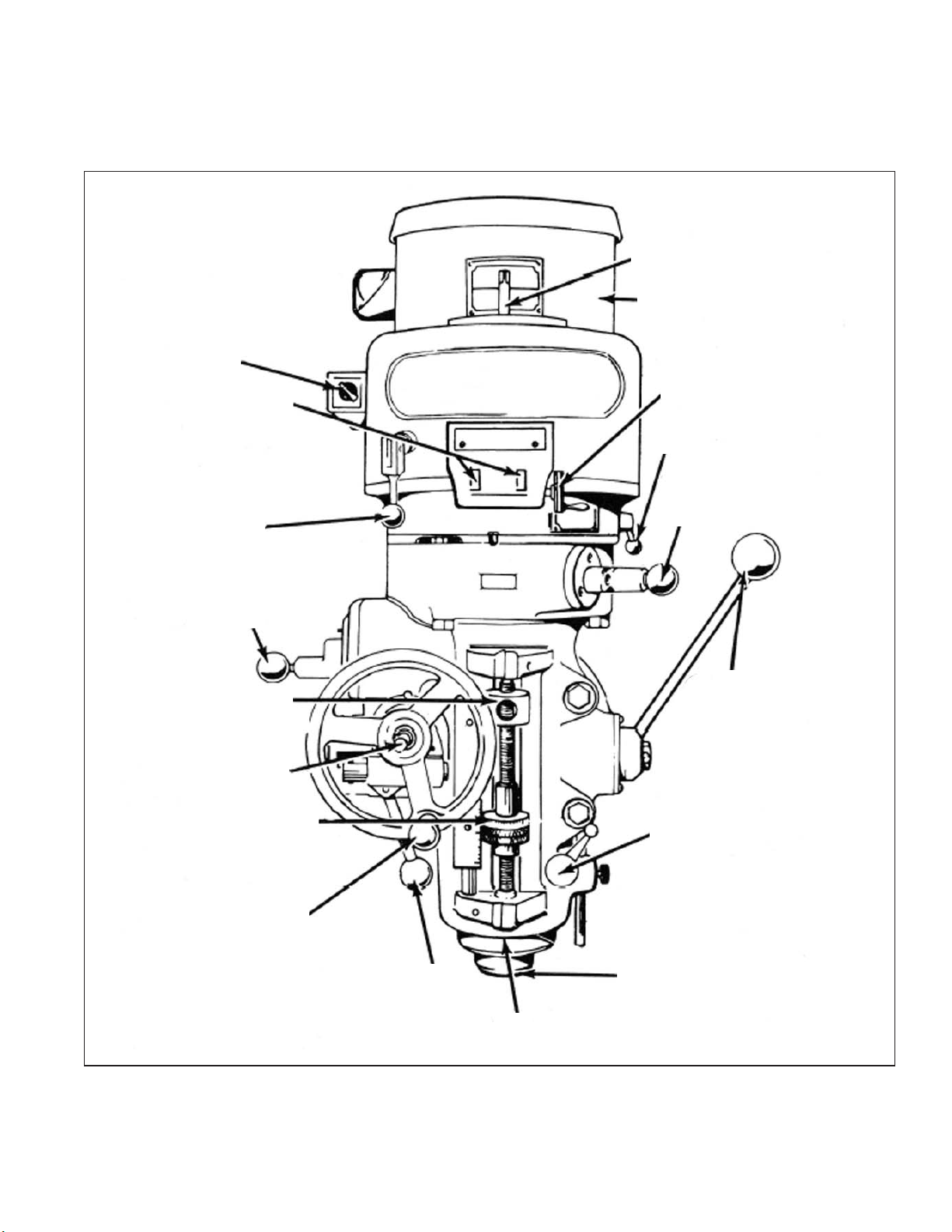
HEAD CONTROLS
R
Q
A
B
C
D
E
G
F
P
O
N
M
L
H
I
J
K
TP5285
Figure 2.1 - Head Controls Parts Assembly
M-508 2-1
Page 28

HIGH-LOW RANGE SWITCH
High-Low Range Switch “A”, Figure 2.2, is a
motor reversing switch. When the attachment is in
direct drive (HIGH SPEED), the motor and spindle
A
are turning in a clockwise direction as viewed from
the top of machine. When the attachment is in “Back
Gear” (LOW SPEED), the spindle will run backwards
(counter-clockwise) unless the motor direction is
reversed by moving switch to “Low”.
The back gear lever is marked Hi-Lo. This will
indicate the proper switch position. They should be
positioned alike or the spindle will run backwards.
- NOTE -
Spindle should run in clockwise position.
Figure 2.2 - High-Low Range Switch
VARIABLE SPEED DIAL
Variable Speed Dial “B”, Figure 2.3, visibly indicates, in windows, the speed range that the
machine is operating in, 60 to 500 low range, 500 to 4200 high range.
TP5286
B
TP5287
Figure 2.3 - Variable Speed Dial
2-2 M-508
Page 29

SPINDLE BRAKE
Spindle Brake “C”, Figure 2.4, can be moved in
either direction to stop spindle; however, when
locking spindle, brake lever should be moved either
by pulling towards the operator or pushing away
from the operator, then raised. When brake is worn
out it has to be replaced. There are no adjustments
to be made.
- CAUTION -
BE certain that spindle brake is re
leased before starting the motor.
This is important as the motor can
be damaged if switch is turned on
with brake in locked position.
C
Lock On
Lock Off
TP5288
Figure 2.4 - Spindle Brake
QUILL FEED SELECTOR
The Quill Feed Selector “D”, Figure 2.5, is used
for selecting the three feeds: .0015”, .003” and .006”
per revolution. It is shifted by pulling knob out and
turning from one position to the other. Feeds are
stamped on cover below indentation hole. Feed is
more readily engaged when spindle is running.
D
TP5289
Figure 2.5 - Quill Feed Selector
M-508 2-3
Page 30

QUILL STOP KNOB
Quill Stop Knob “E”, Figure 2.6, is used to
disengage automatic feed in either direction as well
as the stop point setting working depths.
MICROMETER NUT
Micrometer Nut “F”, Figure 2.6, is used for setting
depths. Each graduation on nut indicates .001” of
depth, it reads directly to scale mounted along the
side of it. Depths may be obtained by setting
micrometer nut in conjunction with quill stop.
E
F
TP5290
FEED REVERSE KNOB
The position of the Feed Reverse Knob “G”,
Figure 2.7, depends upon direction of spindle
rotation. If boring with right hand cutting tools, pull
feed handle towards operator until clutch becomes
engaged.
Neutral position is between forward and reverse
position. It is recommended that the handle be left in
neutral position when not in use.
MANUAL FEED HANDWHEEL
Feed Reverse Knob “G” should be in neutral
position and Feed Control Lever “I”, Figure 2.8
engaged. Clockwise rotation of Manual Feed
Handwheel “H”, Figure 2.7, moves quill down. The
manual feed handwheel and the quill feed handle
may be disengaged by moving them outward about
.125”.
Figure 2.6 - Quill Stop Knob and
Micrometer Nut
Neutral
Up
G
H
Down
TP5291
Figure 2.7 - Feed Reverse Knob and
Manual Feed Handwheel
2-4 M-508
Page 31

FEED CONTROL LEVER
Feed Control Lever “I”, Figure 2.8, engages
overload clutch on pinion shaft when positioned left
and will stay engaged until either quill stop comes in
contact with micrometer adjusting nut, forcing feed
control lever to drop out automatically, or release
manually by engaging lever to right.
FEED CONTROL OVERLOAD CLUTCH
The Feed Control Overload Clutch is set at the
factory to hold up to 200 lbs of down pressure on
quill, which will accommodate drills up to .375”
diameter in mild tool steel.
- CAUTION -
This clutch should not be tampered
with in the field.
Engage
I
Disengage
- NOTE -
The feed control lever must be en
gaged in order to use manual feed
controls. the quill feed handle and
manual feed handwheel may be
removed when not in use.
QUILL
Quill “J”, Figure 2.9, contains the spindle
assembly and can be raised or lowered by using the
quill feed handle “M”, Figure 2.10.
SPINDLE
Spindle “K”, Figure 2.9, performs the actual
rotation and also retains the machine tooling.
QUILL LOCK
Quill Lock “L”, Figure 2.9, is a friction lock for use
when quill is in a stationary position such as a milling
operation. It is recommended that this lock be used
whenever quill movement is not desired.
TP5292
Figure 2.8 - Feed Control Lever and
Feed Control Overload Clutch
J
K
TP5293
L
Figure 2.9 - Quill, Spindle and
Quill Lock
M-508 2-5
Page 32

QUILL FEED HANDLE
Quill Feed Handle “M”, Figure 2.10, is used to
raise and lower the quill manually. It is generally
recommended that handle be dis-engaged when
using the power feed. It may be removed by simply
pulling handle off.
POWER FEED TRANSMISSION ENGAGEMENT CRANK
M
TP5294
Figure 2.10 - Quill Feed Handle
Power Feed Transmission Engagement Crank
“N”, Figure 2.11, engages power feed worm gear.
When lever is in right hand hole, the power feed
worm gear is engaged.
To engage worm gear, pull knob out and crank
handle in clockwise or down direction and move to
opposite position (see Figure 2.12).
- NOTE -
Crank should be rotated counter-clockwise to engage power quill feed. Crank
should be rotated clockwise to disen
-
gage.
- CAUTION -
Power feed worm gear may be en
gaged when spindle is rotating,
however, it should be engaged
gently to avoid damage to worm
gear. The worm gear may be disen
gaged at any time. do not use power
feed at speeds above 3000 RPM.
N
TP5295
Figure 2.11 - Power Feed Transmission
Engagement Crank
Disengaged Engaged
Clockwise
CounterClockwise
TP5296
Figure 2.12 - Worm Gear Disengagement
2-6 M-508
Page 33

HI-NEUTRAL-LO LEVER
The Hi-Neutral-Lo Lever “O”, Figure 2.13, is used to put the attachment into either back gear or
direct drive. Rotate the spindle by hand to facilitate meshing of clutch or gears.
Neutral is provided to permit free spindle rotation for indicating and setup work.
In the high speed position (direct drive) the spindle is driven by tapered clutch teeth. If the clutch is
not meshed tightly, clutch rattle will be heard. This can be corrected by loosening the two securing
screws in lever while in high speed position. The clutch spring will automatically adjust the clutch.
Tighten the two securing crews in lever.
Securing Screws
High
O
Neutral
Low
Figure 2.13 - Hi-Neutral-Lo Lever
- CAUTION -
Do not shift hi-lo lever while motor is running.
TP5297
M-508 2-7
Page 34

SPEED CHANGE HANDWHEEL
- CAUTION -
DO NOT attempt to change spindle RPM unless the motor is running. Dial
speeds will only be approximate. Belt wear will cause a slight variation in
speeds from what is indicated on the dial.
Spindle speeds are adjusted by turning Speed Change Handwheel “P”, Figure 2.14, on the front of
the belt housing. There are two ranges: 60 to 500 and 500 to 4200.
To obtain 60 to 500 (low range):
1. Hold the Hi-Neutral-Lo lever (right rear side
of the attachment) so the gears are clear of
P
one another.
2. Rotate the spindle nose by hand until the
gears line up, then move the Hi-Neutral-Lo
lever to the “Lo” position (back gear).
3. Use the low range on the drum switch to
engage the back gears.
- CAUTION -
- CAUTION -
If the back gears do not mesh, do
Do Not Move
Unless Motor is
Running
not force the lever.
To obtain 500 to 4200 (high range):
1. Hold the Hi-Neutral-Lo lever (right rear side
of the attachment) so the gears are clear of
one another.
2. Rotate the spindle nose by hand until the
gears line up, then move the Hi-Neutral-Lo
lever to the “Hi” position.
3. Set the drum switch to high range.
- CAUTION -
Try to avoid shifting the hi-lo lever when the feed worm is engaged.
Increase
Speed
Decrease
Speed
TP5298
Figure 2.14 - Speed Change Handwheel
2-8 M-508
Page 35

DRAWBAR
When tightening or loosening the Drawbar “R”, Figure 2.15, it is necessary to lock the spindle. To
accomplish this, use the spindle brake which is located on the left side of the belt housing, pulling
towards the operator or pushing away from the operator until it binds, then raise the quill feed handle.
Drawbar has 7/16”-20 right hand thread and should be tightened by hand with normal amount of
pressure using wrench furnished with machine. To loosen collet, back off drawbar and if collet does
not open immediately, give knob on top of drawbar a slight tap. Spindle has non-sticking taper and
collet should release readily.
Q
R
TP5299
Figure 2.15 - Motor and Drawbar
M-508 2-9
Page 36

OPERATIONAL PROCEDURES
Spindle Speed
- CAUTION -
DO NOT change speed when spin
dle is stationary. Change speed only
when spindle is running.
To change speed within range:
1. Start spindle.
2. Turn handwheel “A”, Figure 2.16, to select
required speed.
-
A
TP5300
Figure 2.16 - Spindle Speed Change
Back Gear (Low Speed)
- CAUTION -
DO NOT change range while spindle
is running. Change range only when
spindle is stationary.
To change range from direct to back gear drive:
1. Switch “B”, Figure 2.17, to OFF (Stop spindle
rotation).
2. Move lever “C” through neutral to LOW (This
reverses the spindle rotation).
3. Switch “B” to LOW.
B
C
TP5301
Figure 2.17 - Back Gear Range Change
2-10 M-508
Page 37

Direct Drive (High Speed)
To change range from back gear to direct drive:
1. Switch “B” to OFF (Stop spindle rotation).
2. Move lever “C”, Figure 2.18, through neutral to
HIGH.
3. Rotate spindle by hand until the clutches are
felt to engage.
4. Switch “B” to HIGH.
Quill Feed
FINE HAND FEED
1. Disengage Auto Quill Feed “D”, Figure 2.19.
2. Locate “F” in mid (neutral) position.
3. The quill is now under handwheel control
C
High
Neutral
Figure 2.18 - Direct Drive Lever
Low
TP5302
D
I
H
F
G
Off
E
Engage
On
TP5303
Figure 2.19 - Quill Feed
Fine Hand Feed Control
M-508 2-11
Page 38

AUTOMATIC FEED
- NOTE -
Maximum loading .375” (9.5mm) diameter drill steel.
1. Ensure quill lock “G”, is off.
2. Set micrometer dial “H” to required depth.
3. Engage auto quill feed “D” when motor has stopped
4. Select feed rate “I”.
5. Select feed direction “F”, Figure 2.22.
6. Engage feed trip lever “E”. The feed will automatically trip out at a depth within .010” (.25mm)
7. Hand feed to dead stop for repeating accuracy .001” (.025mm)
- CAUTION -
Do not engage quill feed “D” over 3000 RPM.
Neutral
Up
F
Fine Feed
Handwheel Engage
Figure 2.20 - Quill Feed
Automatic Feed Control
Down
TP5304
2-12 M-508
Page 39

Spindle Brake
Brake lever has capability to rotate in either
direction to brake and lock.
Brake
CAM upwards to lock and prevent movement of
spindle (see Figure 2.21).
Quill Sensitive Hand Feed
Off
Brake
Turn and
Lift to
Lock
TP5306
Figure 2.21 - Spindle Brake
1. Place the handle on the quill feed shaft.
2. Select the most suitable position.
3. Push home until the locating pin engages.
TP5307
Figure 2.22 - Quill Sensitive Hand Feed
M-508 2-13
Page 40

SWIVEL THE BELT HOUSING
- CAUTION -
Incorrect spline alignment can be
caused by unequal tightening of the
locknuts ’J’ causing fluctuation of
the quill feed which can be felt
through the sensitive feed handle. It
is advised to call Hardinge service
department before attempting this
procedure.
1. Loosen three locknuts “J”, Figure 2.23.
MACHINE
- WARNING -
DO NOT remove these locking nuts.
2. Swivel to required angular setting.
3. Tighten three locknuts “J” snugly before final
tightening of locknuts. Run spindle to give
correct spline alignment, then tighten locknuts
securely.
SWIVEL THE TURRET
1. Use wrench supplied with machine to loosen
the four bolts “K”, Figure 2.24.
- WARNING -
DO NOT remove these four bolts.
2. Index to the required setting.
3. Lock the four bolts “K” to 47 lb-ft.
J
Figure 2.23 - Swivel Belt Housing
360°
K
K
K
K
TP5305
TP5308
Figure 2.24 - Swivel Turret
2-14 M-508
Page 41

MOVE THE RAM SLIDE
1. Use wrench provided with machine to loosen
bolts “L” and “M”, Figure 2.25.
2. Use wrench to move the slide to the desired
position using bolt “N”.
3. Tighten bolts “L” and “M”, starting with the rear
bolt.
- NOTE -
It is recommended that on heavy mill
ing work, head should be kept as close
to column as possible, where maxi
mum rigidity is obtained.
SADDLE CLAMPING
When milling with longitudinal table feed only, it is
advisable to clamp the knee to the column (see
Figure 2.28) and the saddle to the knee to add
rigidity to these members and provide for heavier
cuts with a minimum of vibration. The saddle locking
lever is located on the left hand side of the saddle.
L
Figure 2.25 - Ram Slide
Unlock
Rear
M
N
TP5309
Excessive moisture can cause slight table bind.
Use moderate clamping pressure, as this will hold
saddle sufficiently.
Lock
Saddle
Locking Lever
TP5310
Figure 2.26 - Saddle Clamping
M-508 2-15
Page 42

TABLE CLAMPING
The table clamp levers are located on front of
saddle and should always be clamped when
longitudinal movement is not required (see Figure
2.27).
Lock
Table Clamp
Levers
Unlock
Figure 2.27 - Table Clamping
KNEE CLAMPING
The knee clamping levers are at the left side of the knee. Leave clamped at all times unless using
knee in operation (see Figure 2.28).
TP5311
Knee
Clamp
On
Off
TP8033
Figure 2.28 - Knee Clamping
2-16 M-508
Page 43

- NOTES -
M-508 2-17
Page 44

- NOTES -
2-18 M-508
Page 45

CHAPTER 3 - MAINTENANCE
2J-HEAD
MOTOR REMOVAL
1. Run head to adjust to lowest speed.
2. Disconnect power.
3. Remove three screws “A” and cover “B”, Figure
3.1.
4. Using the two screws “A”, compress spring “C”.
5. Rotate the speed changer to the highest
speed.
6. Remove the reversing switch from the belt
housing.
7. Remove the two securing screws “D”.
D
8. Lift the motor and rest the case on stud “E”,
Figure 3.2.
9. Ease the belt over the lower drive disc and
remove the motor.
C
B
A
TP5320
Figure 3.1 - Motor Removal
Front View
E
TP5321
Figure 3.2 - Motor Removal
Side View
M-508 3-1
Page 46

DRIVE BELT REPLACEMENT
1. Remove the motor as described on page
3-1.
2. Remove the three screws “F”, Figure 3.3,
insert into the adjacent tapped holes and
withdraw bearing housing “G”.
3. Remove the two screws and the bushings
“H”.
4. Remove four screws “I” and one screw “J”.
5. Remove four screws securing speed
changer “K”.
6. Remove top housing “L”. Tap to clear the
dowels.
7. Replace the belt.
F
G
I
H
K
L
J
TP5322
TIMING BELT REPLACEMENT
1. Remove the motor.
2. Lower the quill to full extent.
3. Remove the two lower cap screws “M”,
Figure 3.4, from the speed changer
housing.
4. Remove the four cap screws “N”.
5. Remove the top assembly “O”, and tap to
clear dowels
6. Replace the belt.
Figure 3.3 - Drive Belt Replacement
M
O
N
TP5323
Figure 3.4 - Timing Belt Replacement
3-2 M-508
Page 47

BRAKE SHOE REPLACEMENT
1. Remove the top section.
2. Remove the two screws “P”, Figure 3.5.
3. Remove the clutch hub assembly “Q”.
4. Replace the brake shoes “R”.
5. Remove the bearing, drive discs and circlips from the hub assembly “Q”.
6. Replace the bearing and housing “S”.
7. Thread hub “B” through the bearing and reassemble the discs, etc.
S
Q
R
P
Figure 3.5 - Brake Shoe Replacement
TP5324
M-508 3-3
Page 48

HEAD
MICRO FEED TRIP ASSEMBLY AND QUILL REMOVAL
1. Remove screw “A” and ball reverse lever “B”,
Figure 3.6.
2. Remove retaining ring “C”, screw “D” and arm
“E”.
3. Thread shaft “F” through micro nuts and
remove.
4. Remove screw “G” and stop “H”.
B
H
5. Remove quill.
6. Clean all areas, oil liberally and reassemble.
7. Check correct operation of micro feed trip
assembly together with feed trip linkage as
per feed tripping adjustment (see Figure 3.8).
G
A
F
C
E
D
TP5325
Figure 3.6 - Micro Feed Trip Assembly and
Quill Removal
3-4 M-508
Page 49

BALANCE SPRING REPLACEMENT
1. With quill in maximum up position apply quill
lock.
2. Remove screw “I”, hub “J”, and key “K”, Figure
3.7.
3. Remove screws “L”, allowing housing to rotate
slowly releasing spring tension.
4. Lift end of spring from pin on the pinion shaft.
5. Rotate housing “M” counter-clockwise from
head casting.
6. Remove spring from housing and replace.
7. Refit spring to main housing casting. Turn
housing clockwise until spring locates on pin in
pinion shaft.
J
I
1-1/2
Turns
TP5326
M
K
L
Figure 3.7 - Balance Spring Replacement
FEED TRIP ADJUSTMENT
1. Release locknut “N”, Figure 3.8.
2. Engage trip handle lever “P”.
3. Adjust micro nuts against quill stop “O”.
4. Slowly turn adjusting screw “Q” until lever “P”
trips. If set to light will not be able to drill.
5. At this point secure locknut “N”.
6. Check for quick action response.
P
Engage
Q
N
Figure 3.8 - Feed Trip Adjustment
O
TP5327
M-508 3-5
Page 50

COLLET ALIGNING SCREW REPLACEMENT
1. Use felt pen, mark reference line on quill
and nose cap “S”, Figure 3.9.
2. Remove set screw “R”.
3. Unscrew nose cap “S”.
4. Remove lock screw “T” and collet aligning
screw “U”.
5. Replace “U”; insert collet and check that the
dog on the end of the screw does not
interfere with the bottom of the guide slot.
6. Replace lock screw “T”.
7. Replace nose cap “S”; check felt pen
markings for correct alignment.
8. Replace set screw “R”. CAUTION - DO NO
OVERTIGHTEN as this will cause
distortion.
9. Check gap “V” (.003”, .08mm)
R
T
U
S
- CAUTION -
Do not attempt to remove nose
cap before removing set screw
“R”. Doing so will cause serious
damage.
V
T
U
TP5328
Figure 3.9 - Collet Aligning Screw
Replacement
3-6 M-508
Page 51

GIB ADJUSTMENT
ADJUSTMENT OF THE TABLE GIB
The table is equipped with a tapered gib and adjusting screws at the left and right sides of the
table.
To Adjust the Gib:
1. Loosen table clamps "B", Figure 3.10.
2. Clean the slides and apply lubricant.
3. To tighten the gib:
A) Loosen right gib screw "C", Figure 3.11.
B) Tighten left gib screw "A", Figure 3.10, slightly and test the table movement.
C) Repeat step B until a slight drag is felt when moving the table by hand.
D) Tighten the right gib screw.
To loosen the gib:
A) Loosen left gib screw "A", Figure 3.10.
B) Tighten right gib screw "C", Figure 3.11, slightly and test the table movement.
C) Repeat step B until a slight drag is felt when moving the table by hand.
D) Tighten the left gib screw.
A
B
TP8016
Figure 3.10 - Left Table
Gib Adjustment Screw
Figure 3.11 - Right Table
Gib Adjustment Screw
C
TP8017
M-508 3-7
Page 52

ADJUSTMENT OF THE SADDLE GIB
The saddle is equipped with a tapered gib and adjusting screws at the front and rear of the saddle.
To Adjust the Gib:
1. Loosen saddle clamp "D", Figure 3.12.
2. Clean the slides and apply lubricant.
3. Remove wiper retainer "E" and wiper "F", Figure 3.12, to gain access to front gib screw "G",
Figure 3.13.
4. Remove wiper retainer "H" and wiper "I", Figure 3.14, to gain access to rear gib screw "J",
Figure 3.15.
E
D
F
Figure 3.12 - Front Saddle Wiper
and Retainer
H
I
Figure 3.14 - Rear Saddle Wiper
and Retainer
TP8018
TP8021
G
TP8020
Figure 3.13 - Front Saddle
Gib Adjustment Screw
J
TP8023
Figure 3.15 - Rear Saddle
Gib Adjustment Screw
3-8 M-508
Page 53

5. To tighten the gib:
A) Loosen the rear gib screw.
B) Tighten the front gib screw slightly and test the saddle movement.
C) Repeat step B until a slight drag is felt when moving the saddle by hand.
D) Tighten the rear gib screw.
- NOTE -
Press the wipers downward and inward while tightening the mounting screws.
E) Install the wipers and wiper retainers.
To loosen the gib:
A) Loosen the front gib screw.
B) Tighten the rear gib screw slightly and test the saddle movement.
C) Repeat step B until a slight drag is felt when moving the saddle by hand.
D) Tighten the front gib screw.
- NOTE -
Press the wipers downward and inward while tightening the mounting screws.
E) Install the wipers and wiper retainers.
M-508 3-9
Page 54

ADJUSTMENT OF THE KNEE GIB
The knee is equipped with a tapered gib and adjusting screws at the top and bottom of the knee.
To Adjust the Gib:
1. Loosen the two knee clamps located on the left side of the knee.
2. Clean the slides and apply lubricant.
3. Remove wiper "K", Figure 3.16, to gain access to upper gib adjustment screw "L", Figure 3.17.
K
Figure 3.16 - Left Knee Wiper
TP8024
L
TP8025
Figure 3.17 - Upper Knee
Gib Adjustment Screw
3-10 M-508
Page 55

4. To tighten the gib:
A) Loosen lower gib screw "M", Figure 3.18.
B) Tighten the upper gib screw slightly and test the knee movement.
C) Repeat step B until a slight drag is felt when moving the knee by hand.
D) Tighten the lower gib screw.
- NOTE -
Press the wiper downward and inward while tightening the mounting screw.
E) Install the wiper.
To loosen the gib:
A) Loosen the upper gib screw.
B) Tighten lower gib screw "M" Figure 3.18, slightly and test the knee movement.
C) Repeat step B until a slight drag is felt when moving the knee by hand.
D) Tighten the upper gib screw.
- NOTE -
Press the wiper downward and inward while tightening the mounting screw.
E) Install the wiper.
M
TP8026
Figure 3.18 - Lower Knee
Gib Adjustment Screw
M-508 3-11
Page 56

TABLE FEED SCREW BACKLASH ADJUSTMENT
1. Move the table to the center of travel.
2. Insert the larger end of the two-piece backlash adjustment tool, shown in Figure 3.19, into the
left side of the saddle.
3. Loosen lock nut “P”, Figure 3.20, one full turn.
4. Use the smaller end of the backlash adjustment tool to engage lead screw adjusting nut "O".
5. Tighten the lead screw adjusting nut while slowly turning handle “N” until the backlash is .003 to
.005 inches [.08 to .13 millimeters].
6. Use the larger end of the backlash adjustment tool to secure the lock nut.
TP8012
Figure 3.19 - Two-Piece Backlash Adjustment Tool
N
O
P
TP8013
Figure 3.20 - Table Backlash Adjustment
3-12 M-508
Page 57

SADDLE FEED SCREW BACKLASH ADJUSTMENT
1. Move the saddle back (toward the column) 3/4 of the way through the range of travel.
2. Remove four socket head cap screws securing bracket “Q”, Figure 3.21, to knee.
3. Pull the saddle forward to expose lock nut “R” and adjusting nut “S”, Figure 3.22, through the
hole in the front of the knee.
4. Use the larger end of the two-piece backlash
adjustment tool, shown in Figure 3.19, to
loosen lock nut “R”, Figure 3.22.
5. Use the smaller end of the backlash
adjustment tool to engage lead screw adjusting
nut "S".
6. While slowly turning handle “T”, tighten the
adjusting nut until backlash is .003 to .005
inches [.08 to .13 millimeters].
7. Tighten the lock nut.
8. Move the saddle back and replace the four
screws securing bracket “Q”, Figure 3.21, to
the knee.
Q
TP8027
Figure 3.21 Saddle Feed Handle
and Mounting Bracket
R
T
S
TP8011
Figure 3.22 - Saddle Backlash Adjustment
M-508 3-13
Page 58

- NOTES -
3-14 M-508
Page 59

CHAPTER 4 - PARTS LISTINGS
2J-HEAD TOP HOUSING
TP5340
Figure 4.1 - 2J-Head Assembly
M-508 4-1
Page 60

2J-HEAD TOP HOUSING
Item Part Number Description Qty
1 BP 11011033 Screw, Socket Hd Cap, .250”-20 x .750” Lg 3
2 BP 12180094 Cap, Top Bearing 1
3 BP 11181977 Washer, Wave Spring 1
4 BP 11180252 Bearing, Ball, Fafnir #9107 NNP 1
5 BP 11180848 Ring, Snap, #5100-137 1
6 BP 11011069 Screw, Socket Hd Cap, .312”-18 x 6.00” 2
7 BP 11011745 Nut, UNC Hex Jam, .375”-16 1
8 BP 11550001 Motor, 2 HP, Multi Volt, 50/60 1
9 BP 11011148 Screw, Hex Hd Cap, .375”-16 x 1.00” 2
10** BP 12180051 Housing, Upper Belt (see BP 12183923) 1
11 BP 12180066 Stud, Speed Change Chain 1
12 BP 11010535 Pin, Roll, .156”Æ x 1.00” Lg 2
13 BP 11180058 Plate, Speed Change 1
14 BP 12183920 Assembly, Drawbar 1
15 BP 11010606 Pin, Cotter, .093”Æ x .750” 1
16 BP 12180074 Stud, Speed Change Plate Pivot 1
17 BP 11011020 Screw, Socket Hd Cap, #10-32 x .750” 2
18 BP 11180095 Washer 1
19 BP 12180089 Sleeve, Pivot 2
20 BP 12180093 Washer, Drawbar 1
21 BP 11180915 “O”-Ring, Parker # 2-14 1
22 BP 12180056 Housing, Spindle Pulley Bearing Sliding 1
23 BP 11170262 Bearing, #RM9110NPP 1
24 BP 11182124 Insert, Plastic 2
25 BP 12183934 Varidisc, Adjustable Drive A 1
26 BP 11180855 Ring, Retaining, #5102-156 1
27 BP 11182120 Belt, Varispeed 1
28 BP 12180082 Varidisc, Stationary Drive 1
29 BP 12180043 Cap, Brake and Bearing 1
30 BP 11170262 Bearing, #RM9110NPP 1
31 BP 11182081 Spring, Brake 2
32 BP 12180073 Shoes, Brake 2
33 BP 12180078 Spacer, Spindle Pulley 1
34 BP 12180042 Assembly, Spindle Pulley Hub 1
35 BP 11011138 Screw, Hex Hd Cap, .250”-20 x .750” 1
36 BP 12180071 Sleeve, Brake Shoe Pivot Sleeve 1
37 BP 11010513 Pin, Roll, .125” x .437” 1
38 BP 12550007 Key, Drive, Fixed Varidisc 1
39 BP 12550004 Assembly, Key, Drive, Varidisc 1
40 BP 12550006 Varidisc, Stationary Motor 1
41 BP 11011287 Screw, Stainless Steel, .250”-20 x .250” 2
42* BP 11182126 Insert, Plastic Replaceable Type 2
43 BP 12550029 Assembly, Varidisc and Spring 1
44 BP 11182083 Spring, Varidisc Motor Shaft 1
45 BP 11550003 Collar, Adjustable Varidisc Spring 1
46 BP 11011022 Screw, Socket Hd Cap, #10-24 x 1.00” 3
47 BP 11150843 Ring, Snap 1
48 BP 11011052 Screw, Socket Hd Cap, .132”-18 x .750” Lg 1
4-2 M-508
Page 61

Item Part Number Description Qty
49 BP 11182122 Key, Plastic 1
50 BP 11011707 Nut, Hex Jam, .250”-20 1
51 BP 12180084 Key 1
52 BP 12180107 Pin, Taper, #4 x 1.00” 4
53** BP 12180052 Base, Belt Housing (see BP 12183923) 1
54 BP 12180088 Cover, Motor Pulley 1
56 BP 11011552 Screw, Drive, Type U, #0 x .250” 4
58 BP 11182893 Nameplate, Hi-Low Range 1
61 BP 11182894 Nameplate, Quill Feed 1
63 BP 12180053 Housing, Gear 1
64 BP 11011443 Screw, Round Hd Machine, #10-24 x .375” 3
65 BP 11185030 Plate, Gear Housing 1
66 BP 11180818 Ring, Snap, #5100-25 1
67 BP 11182306 Finger, Brake Operating 2
68 BP 12180083 Stud, Brake Finger Pivot 1
69 BP 11192151 Knob, Bakelite, .250”-20 1
70 BP 12190133 Handle, Brake 1
71 BP 12180046 Pin, Brake Lock 1
72 BP 11011260 Screw, Stainless Steel, #10-32 UNF x .250” 1
73 BP 12180104 Sleeve, Brake Lock Shaft 1
74 BP 28025521 Shaft, Brake Lock 1
75 BP 12180069 Cam, Brake Lock 1
78 BP 11011031 Screw, Socket Hd Cap, .250”-20 x .625” 1
80 BP 11011019 Screw, Flat Hd Cap, #10-32 x .500” 1
82 0100204 Screw, Socket Hd Cap, #8-32 x .250” 1
83 BP 12550008 Key 1
* Non-replaceable turcite bushing must be purchased as part of varidisc assembly BP 12550029.
**Items 10 and 53 sold as assembly only.
- NOTE -
IMPORTANT - for 1-1/2 HP, substitute the following parts.
Item Part Number Description Qty
34 BP 12182004 Assembly, Spindle Pulley Hub 1
37 BP 11010513 Pin, Roll, .125” x .437” 1
38 BP 12180102 Key, Pulley 1
39 BP 11182121 Key, Plastic 1
40 BP 12180080 Varidisc, Stationary Motor 1
42* BP 11182123 Insert, Plastic 2
43 BP 12180165 Assembly, Varidisc and Spring 1
45 BP 11182305 Collar, Adjustable Varidisc Spring 1
47 BP 11180860 Ring, Snap 1
* Non-replaceable turcite bushing must be purchased as part of varidisc assembly BP 12180165.
M-508 4-3
Page 62

2J-HEAD BACK GEAR
TP5341
Figure 4.2 - 2J-Head Back Gear Assembly
4-4 M-508
Page 63

2J-HEAD BACK GEAR
Item Part Number Description Qty
1 BP 11011710 Nut, Hex, .312” 1
2 BP 11180133 Dial, Spindle Speed 1
3 BP 11183646 Bushing, Bronze, .502” x .628” x 5.00” 1
4 BP 11011380 Screw, Full Dog Socket Hd Set, .250”-20 x .500” 1
5 BP 12180055 Housing, Speed Changer 1
6 BP 12182003 Block, Plastic Bearing 1
7 BP 11011031 Screw, Socket Hd Cap, .250”-20 x .625” 4
8 BP 11010516 Pin, Roll, .125” x .625” Lg 1
9 BP 11010520 Pin, Roll, .125”Æ x 1.00” Lg 1
10 BP 11183720 Chain, Speed Changer, Morse #35 1
11 BP 12180066 Stud, Speed Change Chain 1
12 BP 12180051 Housing, Belt (see BP 12183923) 1
13 BP 12180094 Cap, Top Bearing 1
14 BP 11011065 Screw, Socket Hd Cap, .312”-18 x 4.00” 1
17 BP 12182001 Hub, Speed Change 1
18 BP 11181233 Screw, Socket Hd Set, .250”-UNC x .375” 2
19 BP 11182178 Handle, Machine, #3302 1
20 BP 11182892 Plate, Caution 1
24 BP 11011287 Screw, Stainless Steel, .250”-20 x .250” 2
25 BP 11011037 Screw, Socket Hd Cap, .250”-20 x 1.250” 4
27 BP 11183645 Bushing, Oilite 1
28 BP 28300619 Pin, Roll, 2.5mm x 12mm Lg 1
29 BP 28025716 Shaft, Speed Changer 1
30 BP 28007307 Gear, Boston Worm 1
31 BP 11180214 Bushing, Oilite Flanged, FB 1
32 BP 11010539 Pin, Roll, .187”Æ x .375” Lg 1
33 BP 12180090 Gear, Speed Changer Spur 1
34 BP 11181923 Washer, Wavy Spring 1
35 BP 12180065 Drum, Speed Change Chain 1
36 BP 11552106 Belt, Timing 1
37* BP 12180042 Hub, Spindle Pulley 1
38* BP 12180064 Sleeve, Timing Pulley Clutch 1
39 BP 12180059 Hub, Splined Gear 1
40** BP 12180062 Gear, Spindle Bull (see BP 12183933) 1
41 BP 11180254 Bearing, Ball, Fafnir #RM9308NPP 2
42 BP 11180803 Ring, Snap, #5000-244 2
43 BP 12180063 Spacer, Bull Gear Bearing 1
44 BP 12180053 Housing, Gear 1
45 BP 11181650 Bolt, Tee 3
46 BP 11181906 Washer, Flat, .469” ID x .938” OD x .063” 3
47 BP 11011750 Nut, HDN Finished Hex Jam, .438”-14 3
48 BP 11181986 Washer, Ball Bearing Gear Sleeve 3
49*** BP 12183924 Bracket, Fixed Clutch 1
50 BP 11011246 Screw, Socket Hd Set, .312”-18 x .312” 2
51 BP 28025615 Guide 2
52 BP 28025671 Screw, Flat Socket Hd Cap, #10-32 x .375” 2
53 BP 11010511 Pin, Roll, .125” x .250” Lg 1
54 BP 11183104 Cup, Oil, Gits #1202 Style L 1
M-508 4-5
Page 64

Item Part Number Description Qty
55 BP 11182071 Spring, Compression, .375” OD x .3.00” Lg 3
56 BP 11181794 Locknut, Bearing, #–08 1
57*** BP 12183924 Sleeve, Bearing 1
58 BP 11181977 Washer, Wave Spring 1
59 BP 12180067 Pinion, Bull Gear Shift 1
60 BP 12180161 Plate, Hi-Low Detent 1
61 BP 11181732 Nut, Hex, .375”-16 3
62 BP 11151913 Lockwasher, .375” 3
63 BP 12180085 Stud 3
66 BP 12180100 Plunger, Hi-Low Detent 1
67 BP 11182072 Spring, .750” x .032 x .563” 1
68 BP 11011017 Screw, Socket Hd Cap, #10-32 x .500” Lg 2
69 BP 11192151 Knob, Bakelite, .250”-20 1
70 BP 12180099 Crank, Hi-Low Shift 1
71 BP 12180096 Block, Hi-Low Pinion 1
72 BP 11010516 Pin, Roll, .125” x .625” Lg 1
73 BP 11011052 Screw, Socket Hd Cap, .132”-18 x .750” Lg 4
74 BP 11181007 Screw, Socket Hd Cap, #8-32 x .625” 2
75 BP 11011022 Screw, Socket Hd Cap, #10-24 x 1.00” 1
76 BP 12180088 Cover, Motor Pulley 1
78 BP 11013079 Key, Woodruff #9 2
79 BP 11180235 Bearing, #203NPP-C8 2
80 BP 12180075 Shaft, Bull Gear Pinion Counter 1
81 BP 12180103 Key, Sq, .312” x .540” 1
82 BP 11181975 Washer, Wave Spring 1
83** BP 28025529 Pinion, Bull Gear (see BP 12183933) 1
84 BP 12180076 Cap, Bull Gear Pinion Bearing 1
85 BP 11011011 Screw, Socket Hd Cap, #10-24 x .625” Lg 2
86 BP 12550016 Pulley, Timing Belt 1
87 BP 11191738 Nut, Hex Jam, .625”-18 1
88 BP 11182912 Nameplate, Speed Change 1
89 BP 11011139 Screw, Flat Hd Machine, #8-32 x .750” 2
90 BP 11182897 Plate, Lubrication 1
93 BP 11598117 Assembly, Reversing Switch 1
*Items 37 and 38 sold as assembly only.
**Items 40 and 83 sold as assembly only.
***Items 49 and 57 sold as assembly only.
- NOTE -
IMPORTANT - For 1-1/2 HP, substitute the following parts.
Item Part Number Description Qty
36 BP 11182106 Belt, Timing 1
37 BP 12182004 Hub, Spindle Pulley 1
86 BP 12180091 Pulley, Timing Belt 1
4-6 M-508
Page 65

2J- AND J-HEAD LOWER HOUSING
TP5343
Figure 4.3 - 2J- and J-Head Lower Housing Assembly
M-508 4-7
Page 66

2J- AND J-HEAD LOWER HOUSING
Item Part Number Description Qty
1 BP 11011445 Screw, Round Hd Machine, #10-24 x .375” Lg 3
2 BP 12190163 Washer, Bevel Pinion 1
3 BP 12190203 Gear, Feed Bevel Pinion 1
4 BP 12190164 Sleeve, Feed Worm Gear Shaft 1
5 BP 11192303 Bushing, Worm Cradle 1
6 BP 11011287 Screw, Stainless Steel, .250”-20 x .250” 2
7 BP 12190165 Spacer, Worm Gear 1
8 BP 12190166 Gear, Feed Drive Worm 1
9 BP 12190167 Shaft, Feed Drive Worm Gear 1
* BP 12193440 Assembly, Gear Drive Shaft 1
10* BP 12190162 Key, Worm Shaft, Sq, .125” x .312” 3
11 BP 11013078 Key, Woodruff #7 3
12 BP 11191796 Locknut, Flexlok, .375”-24 1
13 BP 12190199 Washer, .375” 1
15 BP 11192209 Gear, Feed Reverse Bevel 1
16 BP 12190168 Pin, Feed Engage 1
17 BP 12190059 Cradle, Worm Gear 1
18 BP 12190169 Throw-Out, Worm Gear Cradle 1
19 BP 12190170 Sleeve, Shift 1
20 BP 12190138 Pin, Shift 2
21 BP 11192052 Spring, Compression 2
22 BP 11010517 Pin, Roll, .125” x .750” 2
23 BP 12190064 Crank, Shift (see BP 12193443) 1
24 BP 11192151 Knob, Bakelite, .250”-20 4
25 BP 11011010 Screw, Socket Hd Cap, #10-24 x .500” Lg 7
26 BP 11011258 Screw, Set, #10-24 x .375” 1
27 BP 12190181 Bushing, Cluster Gear Shaft Upper 1
28 BP 28007099 Assembly, Cluster Gear (see BP 12193504) 1
29 BP 12190148 Key, Sq, .125” x 1.750” 1
* BP 12193544 Assembly, Bevel Feed Pinion 1
30* BP 12190175 Assembly, Key, Sq, .125” x .563” 2
31 BP 12193517 Shaft, Cluster Gear 1
32** BP 11190836 Ring, External Retaining, #5100-62 2
33** BP 12190149 Bearing, Bevel Gear 1
34** BP 12190150 Spacer, Bevel Gear Thrust 1
35** BP 12190180 Pinion, Feed Reverse Bevel 1
36* BP 12190146 Gear, Feed Driving 1
37* BP 12190176 Key, Round End, Sq, .125” x .750” 1
38* BP 12190145 Shaft, Cluster Gear Input 1
40* BP 12190144 Gear, Feed Drive 1
41 BP 11190310 Bearing, Needle, Torrington #B-66 1
42 BP 11193637 Bushing 1
43 BP 28007307 Gear, Worm Speed Control 1
44 BP 12190155 Bushing, Feed Worm Shaft 1
45 BP 11011268 Screw, Stainless Steel, Cup 6
46 BP 11011542 Screw, Set, .312”-18 x .938” 5
47 BP 11190152 Washer, Feed Worm Shaft Thrust 1
4-8 M-508
Page 67

Item Part Number Description Qty
* BP 12193435 Assembly, Bevel Feed Gear 1
48* BP 11183646 Bushing, Bronze, .502” x .628” x 5.00” 2
49* BP 12193432 Gear, Feed Reverse Bevel 2
50 BP 12190153 Clutch, Feed Reverse 1
53 BP 11011547 Lock, Screw, Stainless Steel, .312”-18 x .156” 1
54 BP 11011375 Screw, Stainless Steel, .312”-18 x .312” 1
55 BP 12190157 Rod, Reverse Clutch 1
56 BP 11010509 Pin, Roll, .093” x .750” 1
57 BP 12190198 Shaft, Feed Worm 1
58 BP 12190200 Pin, .093” x .312” Lg 1
59 BP 28007308 Pin, .100 x .438” Lg 1
60 BP 12190179 Rod, Feed Shift 1
61 BP 11011260 Screw, Stainless Steel, #10-32 UNF x .250” 1
63 BP 11190061 Fork, Feed Gear Shift 1
64 BP 12193446 Assembly, Cluster Gear Shift Crank 1
66 BP 12190065 Cover, Cluster Gear 1
73 0100424 Screw, Cap, #10-24 x 1.500” 2
74 BP 12190188 Pin, Stop 2
75 BP 12190098 Ring, Clutch 1
76 BP 11011265 Screw, Stainless Steel, .250”-20 x .250” 1
77 BP 12190073 Plug, Brass, .187”Æ x .093” 1
78 BP 12190105 Locknut, Overload Clutch 1
79 BP 11192055 Spring, Safety Clutch 1
80 BP 11192302 Clutch, Overload 1
81 BP 12193549 Sleeve, Overload Clutch 1
82 BP 11191920 Washer, Single Spring 3
83 0350210 Screw, Round Hd Machine, #8-32 x .625” 3
88 BP 11192032 Spring, Compression, .250”Æ x 1.250” 1
89 BP 12190096 Plunger, Overload Clutch Lever Spring 1
90 BP 12190106 Bushing, Quill Pinion Shaft 1
91 BP 12190104 Spacer, Pinion Shaft Worm Gear 1
92 BP 12190103 Gear, Overload Clutch Worm 1
93 BP 12190102 Ring, Overload Clutch 1
94 BP 11190870 Ring, External Retaining 1
95 BP 11010717 Pin, Dowel, .187” x .750” 1
96 BP 12193427 Assembly, Overload Clutch Trip Lever 1
97 BP 12190097 Washer, Overload Clutch 1
98 37 000823102 Ring, External Retaining, #5100-37 1
99 BP 12190068 Cover, Clutch Arm 1
101 BP 11011740 Nut, Hex Jam, .250”-20 1
102 BP 11010717 Pin, Dowel, .187” x .750” 1
103 BP 12190094 Rod, Cam 1
104 BP 12190095 Handle, Trip 1
106 BP 12190067 Bracket, Feed Trip 1
107 BP 11011035 Screw, Socket Hd Cap, .250”-20 x 1.00” 1
111 BP 12193433 Assembly, Reverse Knob 2
113 BP 12190159 Assembly, Handwheel Clutch (see BP 12193519) 1
116 BP 12190154 Assembly, Handwheel Clutch Spring 1
117 BP 11010515 Pin, Roll, .125” x .562” 1
118 BP 12190093 Assembly, Cam Rod Sleeve 1
M-508 4-9
Page 68

Item Part Number Description Qty
119 BP 11010513 Pin, Roll, .125” x .437” 1
120 BP 11192053 Spring, Compression 1
121 BP 12190091 Plunger, Trip 1
122 BP 12190092 Bushing, Feed Trip Plunger 1
123 BP 12190090 Bushing, Trip Plunger 1
125 BP 12190089 Plunger, Feed Trip 1
125 BP 12193519 Assembly, Handwheel 1
127 BP 12190191 Spindle 1
128 BP 11190081 Skirt, Quill 1
129 BP 11191790 Locknut, #06 1
130 BP 11191942 Lockwasher, #W-06 1
131 BP 11190237 Bearing, Spindle 1
132 BP 12190197 Sleeve, Bearing 1
133 BP 12190196 Nosepiece 1
134 BP 12780915 Shield, Spindle Dirt 1
135 BP 11190238 Bearing, Spindle, Set 1
136 BP 12193513 Bearing, Spindle, Set 1
139 BP 11011265 Screw, Stainless Steel, .250”-20 x .250” 1
140 BP 12193540 Screw, Set, R-8 Collet 1
141 BP 11011545 Screw, Locking Set, .250”-32 x .125” 1
142* BP 12190192 Quill (See BP 12194541) 1
143 BP 28300336 Nut, Steel, #6-32 NC 1
144 BP 28300609 Screw, Stainless Steel, #6-32 x .750” 1
145 BP 28007042 Lever, Feed Trip (see BP 12193498) 1
146 BP 12190185 Pin, Trip Lever 1
147 BP 12200103 Rod, Indicator 1
148 BP 12190109 Sleeve, Quill Lock, Tapped 1
149 BP 12200098 Handle, Lock 2
150 BP 11011595 Screw, Washer Hd Machine, #10-32 x .375” 1
151 BP 11192403 Strainer, Felt 1
152 BP 12190111 Bolt, Quill Lock 1
153 BP 12190110 Sleeve, Quill Lock, Untapped 1
154 BP 12200102 Screw, Rod Indicator Thumb 4
155 BP 12191620 Bolt, Tee, .500” 2
156 BP 12190135 Spacer, Lower Clamping Bolt 2
157 BP 12191736 Nut, Hex, .500” x 1.500” 2
158 0350104 Screw, Round Hd Machine, #6-32 x .250” 1
159 BP 11195306 Scale, Quill Micrometer Inch 1
162 BP 12190344 Assembly, Quick Nut 1
163 BP 12190082 Nut, Quill Stop 1
164 BP 12190083 Screw, Quill Stop Micro 1
165 BP 11011121 Screw, Socket Hd Cap, .375”-24 x .625” 1
166 BP 28007063 Shaft, Quill Pinion 1
168 BP 12200111 Pin, Spring 1
170 BP 11010541 Pin, Roll, .187” x .750” Lg 1
171 BP 11013076 Key, Woodruff #3 1
172 BP 12190182 Screw, Pinion Shaft Hub 1
173 BP 11192165 Ball, Steel 1
174 BP 11192054 Spring, Compression 1
175 BP 12201033 Assembly, Quill Feed Handle 1
4-10 M-508
Page 69

Item Part Number Description Qty
176 BP 12190079 Hub, Quill Pinion 1
177*** BP 12190066 Cover, Spring 1
178*** BP 11192020 Spring, Clock 1
179*** BP 28007150 Pin, Outside Clock Spring 1
180 BP 28007064 Pinion, Quill (see BP 12190108) 1
183 BP 12190085 Lever, Reverse Trip Ball 1
184 BP 12190086 Plunger, Feed Reverse Trip 1
185 BP 12190087 Screw, Reverse Trip Ball Lever 1
186 BP 11192207 Gear, Worm 1
187 5 0001465 Key, Woodruff #405 1
188 BP 11011370 Screw, Socket Hd Set, .250”-UNC x 20 x .375” 1
189 BP 12190850 Shaft, Adjustable Worm 1
192* BP 12190051 Housing, Quill (see BP 12194541) 1
193 BP 11193111 Cup, Oil 1
196 BP 12190162 Key, Worm Shaft, Sq, .125” x 5/16” 1
*Items 10, 36, 37 and 40 sold as assembly BP 12193440.
**Items 32, 33, 34 and 35 sold as assembly BP 12193544.
***Items 177, 178 and 179 sold as assembly BP 12193437.
M-508 4-11
Page 70

BASIC MACHINE
TI5727
Figure 4.4 - Basic Machine Assembly
4-12 M-508
Page 71

BASIC MACHINE
Item Part Number Description Qty
1 BK 0001500C141 Body 1
2 BK 0001500C103 Column 1
3 BK 0001500C139 Elevating screw nut (Inch) 1
4 BK 0001500C137 Elevating screw (Inch) 1
5 BK 0001500C077 Bevel gear (Big) 1
6 BK 0001500C175 Knee 1
7 BK 0001500C096 Bevel gear (Small) 1
8 BK 0001500C094 Elevating shaft 1
9 BK 0001500C092 Bearing Housing 1
10 BK 0001500C090 Bearing Cap 1
11 BK 0001500C088 Dial holder 1
12 BK 0001500C1381 Dial with 100 graduation (Inch) 1
13 BK 0001500D021 Dial nut 1
14 BK 0001500C085 Gear shaft clutch insert 1
15 BK 0001500C084 Knee knob 1
16 BK 0001500C083 Ball crank handle lever 1
17 BK 0001500C055 Knee clamp 1
18 BK 0001500C041 Clamp adjusting screw 2
19 BK 0001500C044A Scraper set 1
20 BK 0001500C044B Scraper set 1
21 BK 0001500C0611 Dustproof cover 1
22 BK 0001500C060A1 Dustproof cover 1
23 BK 0001500C118 Spider 1
24 BK 0001500C124 Turret 1
25 BK 0001500C120 Ram pinion 1
26 BK 0001500C126 Ram lock plunger 2
27 BK 0001500C037 Table lock bolt handle 4
28 BK 0001500C110 Gib lock screw 2
29 BK 0001500C128 Ram pinion set 1
30 BK 0001500C127 Locking bolt 4
31 BK 000146603 Nut, 1/2" 1
32 BK 0001500C172 Ram 1
33 BK 0001500C002 Ram adaptor 1
34 BK 0001500C001 Tilting worm 1
35 BK 0001500C011 Hook 1
36 BK 0001500C008 Vertical adjusting worm shaft 1|
37 BK 0001500C019 Adaptor locking bolt 3
38 BK 0001500C004 Adaptor pivot stud locknut 1
39 BK 000284001 Washer, M14 3
40 BK 0001500C017 Head housing shaft 1
41 BK 000823126 Snap Ring, M26 2
44 BK 000631702 Key, 5 X 5 X 50 1
45 BK 0001500C006 Worm 1
46 BK 0001500C012 Worm thrust washer 1
47 BK 0001500C003 Adaptor scale 1
48 BK 0001500C125 Column side cover 2
49 BK 0001500C130 Oil filter 2
50 BK 000631703 Key, 5 X 5 X 15 2
M-508 4-13
Page 72

Item Part Number Description Qty
51 BK 000026602 Bearing 1
52 BK 0001500C076 Washer 5
53 BK 000026601 Bearing 2
54 BK 000146602 Nut, 3/8 2
55 BK 000033804 Hexagon socket screw 3
56 BK 0001500C170B Leveling screw 4
57 BK 0001800C146 Leveling pads 4
58 BK 000631704 Key, 4 X 4 X 20 1
59 BK 000033805 Hexagon socket screw, M6 X 20 6
62 BK 000033806 Hexagon socket screw, M6 X 16 8
63 BK 000026603 Bearing 1
64 BK 0001500C069 Knee lock plunger 1
65 BK 000033807 Hexagon socket screw, M10 X 20 2
66 BK 000033808 Hexagon socket screw, M5 X 1 4
67 BK 000033802 Cross-Recessed Head Screw 2
68 BK 000033809 Screw, M2 X 5 6
69 BK 0001500C144 Zeroing Point Plate 1
70 BK 001032701 Nipple, 1/8PT 1
71 BK 0001500C007 Washer 1
72 BK 0001500C111 Turret-ram gib 1
73 BK 000033810 Set Screw, M6 X 10 1
74 BK 000146604 Hexagon socket nut 1
77 BK 0001500C048 Turret scale 1
78 BK 0001500C015 Angle plate 1
81 BK 0001500C013 Ram scale 1
82 BK 0001500C318 Body set screw 2
83 BK 0001500C317 Dust cover screw 1
Not Shown:
84 BK 0001500C134 Backlash adjustment tool 2
85 BK 0008150 K Box wrench kit 1
86 BK 0001500C136 Tool Box 1
87 BK 000815001 Open-End Wrench 1
4-14 M-508
Page 73

TABLE AND LEAD SCREW ASSEMBLY
TI5728
Figure 4.5 - Table and Lead Screw Assembly
M-508 4-15
Page 74

TABLE AND LEAD SCREW ASSEMBLY
Item Part Number Description Qty
1 BK 0001500C035 Table 1
2 BK 0001500D024B Right leadscrew bracket 1
3 BK 0001500D023B Left leadscrew bracket 1
4 BK 0001500D005 Right dial holder 1
5 BK 0001500D0161 Dial (inch) 3
6 BK 0001500C086 Dial nut 3
7 BP 12060271 Ball crank handle 3
9 BK 0001500D006 Lock nut 2
10 BK 0001500D021 Left dial holder 2
11 BK 0001500D022 Feed nut bracket 1
12 BK 0001500D074A X leadscrew 1
13 BK 0001500D033A X lead screw nuts (Inch) 2
14 BK 0001500D017 Backlash adjustment nut 2
15 BK 000631701 Key, 3 X 3 X 20 3
16 BK 0001500D034A Cross feed screw nut (Inch) 2
17 BK 000631702 Key, 5 X 5 X 50 2
18 BK 0001500D076 Y leadscrew 1
19 BK 0001500D025A Cross feed bearing bracket 1
21 BK 000026601 Bearing 1
22 BK 001150101 Bearing washer 2
23 BK 000026604 Bearing 4
24 BK 0001500C031 T bolt 2
25 BK 0001500C032 Table stop piece 2
26 BK 0001500C073 Washer 2
27 BK 000146601 Nut, 1/2 3
28 BK 000033801 Screw, 3/8 X 1 16
29 BK 000146602 Nut, 3/8" 2
30 BK 000142401 Overload clutch lever spring plunger, 5 X 30 2
33 BK 000142402 Overload clutch lever spring plunger, 6 X 25 6
35 BK 0001500C052 Saddle 1
36 BK 0001500C043 Saddle table jib 1
37 BK 0001500C041 Adjusting screw 4
38 BK 0001500C049 Gib (left & right) 1
39 BK 0001500C039 Saddle lock plunger 1
41 BK 0001500C059 Table lock plunger 2
42 BK 0001500C037 Table lock bolt handle 3
43 BK 0001500C044 Felt wipers 2
44 BK 000033802 Cross-Recessed Head Screw, 3/16 X 3/8 8
45 BK 0001500C042 Table stop bracket 1
46 BK 000033803 Hexagon socket screw 2
4-16 M-508
Revised: August 3, 2011
Page 75

FLOOD COOLANT
TP5347
Figure 4.6 - Flood Coolant Assembly
Item Part Number Description Qty
1 BP 11713642 Tank, Pump and Motor 1
2 BP 11715470 Tubing, Coolant Pressure Hose, Vinyl, .50”Æ x .625” 10 ft
3 BP 11565476 Valve, Check 1
4 BP 12561010 Block, Manifold 1
7 BP 11565470 Tubing, Drain Hose, Vinyl, .750” x 1000” 15 ft
One Nozzle
5 BP 11563490 Valve, Shut-Off 1
6 BP 11560264 Hose, Flexible Nozzle Coolant, 21” Lg 1
Two Nozzles
5 BP 11563490 Valve, Shut-Off 2
6 BP 11560264 Hose, Flexible Nozzle Coolant, 21” Lg 2
M-508 4-17
Page 76

LUBRICATION SYSTEM
1
2
3
4
5
TP8034
Figure 4.7 - Lubrication System Assembly
Item Part Number Description Qty
1 BP 11060490 Ferrule 1
2 BP 11060491 Nut 1
3 BP 11060492 Lubricator Kit 1
4 BP 11060493 Plug 1
5 BP 11060494 Adapter 1
4-18 M-508
Page 77

REPLACEMENT MOTOR ASSEMBLIES AVAILABLE
Motor Assembly 2J-Head 2 HP Unified without NFPA, BP 12550150
Part Number Description Qty
BP 11010514 Pin, Roll, .125” x .500” 1
BP 11011595 Screw, Washer Hd Machine, #10-32 x .375” 1
BP 11012759 Marker, 208 Volts 1
BP 11012760 Marker, 230 Volts 1
BP 11012761 Marker, 380 Volts 1
BP 11012762 Marker, 460 Volts 1
BP 11012770 Marker, 200 Volts 1
BP 11012771 Marker, 400 Volts 1
BP 11012772 Marker, 416 Volts 1
BP 11150843 Ring, Retaining, #5100 1
BP 11182556 Set, Cord, 14/4 600 Volts 1
BP 11182557 Assembly, Cable, 600 Volts 1
BP 11182655 Switch, Drum 1
BP 11550001 Motor, 2 HP, Multi Volt, 50/60 1
BP 11562534 Nut, Wire 1
BP 12550029 Assembly, Varidisc and Spring 1
BP 12550007 Key, Drive, Fixed Varidisc 1
BP 12550006 Varidisc, Motor Stationary 1
Motor Assembly 2J-Head 2 HP Unified with NFPA
Contact Sales Department for Part Number
M-508 4-19
Page 78

Motor Assembly 2J-Head 2 HP 575 Volts without NFPA, BP 12550020
Part Number Description Qty
BP 11010514 Pin, Roll, .125” x .500” 1
BP 11012763 Marker, 575 Volts 1
BP 11150843 Ring, Retaining, #5100-118 1
BP 11182556 Set, Cord, 14/4 600 Volts 1
BP 11182557 Assembly, Cable, 600 Volts 1
BP 11182655 Switch, Drum 1
BP 11011595 Screw, Washer Hd Machine, #10-32 x .375” 1
BP 11550101 Motor, 2 HP, 575-3-60 1
BP 12550006 Varidisc, Motor Stationary 1
BP 11562534 Connector, Wire Nut, M Type Y 3
BP 12550007 Key, Drive, Fixed Varidisc 1
BP 12550029 Assembly, Varidisc and Spring 1
Motor Assembly 2J-Head 2 HP 575 Volts with NFPA
Contact Sales Department for Part Number
Replacement Motors Available
Part Number Description Qty
BP 11190161 Motor,1 HP, 230/460
BP 11190162 J-Head 1 HP 575 Volts
BP 11550001 Motor, 2 HP, Multi Volt, 50/60
BP 11550101 Motor, 2 HP, 575-3-60
4-20 M-508
Page 79

2J Milling Head (1-1/2 HP) – Spare Parts
Part Number Description Qty
BP 11182120 Belt, Varispeed 1
BP 11182106 Belt, Timing 1
BP 12180073 Shoe, Brake, Set 1
BP 11182081 Spring, Brake 1
BP 11182121 Key, Motor 1
BP 11182122 Key, Plastic 1
BP 12193437 Assembly, Clockspring and Cover 1
BP 12180117 Lubricant, Gear 1
BP 11183147 Lubriplate 1
BP 11190238 Bearing, Spindle, Pair 1
BP 11190237 Bearing, Spindle 1
BP 11192403 Strainer, Felt 2
BP 11191942 Lockwasher 2
BP 12193540 Screw, Set, R-8 Collet 6
2J Milling Head (2 HP) – Spare Parts
Same as above except:
Part Number Description Qty
BP 11552106 Belt, Timing 1
BP 12550004 Assembly, Key, Drive, Varidisc 1
BP 11182122 Key, Plastic 1
METRIC CONVERSION KITS
BP 2184000 – 2J-Head, Metric Conversion Kit
Part Number Description Qty
BP 11195307 Scale 1
BP 12191013 Assembly, Stop 1
M-508 4-21
Page 80

- NOTES -
4-22 M-508
Page 81

CHAPTER 5 - SPECIFICATIONS
PRINCIPLE DIMENSIONS
Left Side View of Machine
MACHINE
TP5264
Figure 5.1 - Machine Principle Dimensions: Side View
ABCDEF
MIN 82” (2083) 51” (1295) 8.750” (222) 2.500” (64) 0 6.750” (171)
MAX 82” (2083) 63” (1600) 20.750” (527) 18.500” (470) 12” (305) 18.750” (476)
Note: Metric specifications in parenthesis
M-508 5-1
Page 82

Top View of Machine
36¼ [921]
24 [610]
20 [508]
63 [1600]
29½ [749]
99½ [2527]
NOTE: All dimensions shown as inches [millimeters].
TP5265A
Figure 5.2 - Machine Principle Dimensions: Top View
5-2 M-508
Page 83

MACHINE SPECIFICATIONS
Range
Table Travel (X-Axis)
without Power Feed 36 in. (914 mm)
with Power Feed 33.5 in. (851 mm)
Saddle Travel (Y-Axis) 12in. (305 mm)
Quill Travel 5 in. (127 mm)
Knee Travel (Z Axis)
without Flood Coolant 16 in. (406 mm)
with Flood Coolant 15 in. (381 mm)
Ram Travel 12 in. (305 mm)
Throat Distance
Minimum 6.75 in. (171 mm)
Maximum 18.75 in (476 mm)
Table to Spindle Nose Gage Line
Minimum 2.5 in. (64 mm)
Maximum 18.25 in. (463 mm)
Table
Overall Size 49 x 9 in. (1245 x 229 mm)
T-Slot Centers 3 @ 2.5 in. (64 mm)
T-Slot Size .625 in. (16 mm)
Height Above Floor (Maximum) 47.25 in. (1200 mm)
Spindle (2J Head)
Power Rating
30 Minute Duty Cycle 3 HP (2.2 Kw)
Continuous 2 HP (1.5 Kw)
Standard Spindle
Spindle Taper R-8
Tooling R-8 Collets
Optional Spindle
Spindle Taper #30 ISO
Tooling Erickson Quick-Change #30 ISP
Speed Range
High (Infinitely variable) 500 - 4200 rpm
Low 60 - 500 rpm
Power Feed Quill 0.0015 in/rev (0.038 mm)
Manual Adjust 0.003 in/rev (0.076 mm)
0.006 in/rev (0.152 mm)
M-508 5-3
Page 84

Drilling Capacity
Power Quill Feed 3/4 in. (19 mm)
Milling Capacity (mild steel) 3/4 in. (19 mm)
Boring Capacity (mild steel) 6 in. dia. (152 mm)
Spindle Diameter 1.875 in. (48 mm)
Quill Diameter 3.375 in. (86 mm)
Space and Weight
Floor Area (Power case door closed) 8.3 x 5.3 ft. (2.53 x 1.62 m)
Floor Area (Power case door open) 8.3 x 7.8 ft. (2.53 x 2.4 m)
Height 7.04 ft. (2.15 m)
Net Weight 1930 lb (875 Kg)
Shipping Weight 2075 lb (941 Kg)
Electrical Supply
Input Voltage 208/230/460
Electrical Phase 3
Frequency 50/60 cycle
Power Capacity 4 KVA
5-4 M-508
Page 85

2J-HEAD
GENERAL SPEED RECOMMENDATIONS
FEET PER MINUTE
ROUGH ROUGH AND LIGHT AND
MATERIAL TO BE CUT CUT FINISH FINISH CUT
Cast Iron – Soft (Under 150 Brinnell) 70 80 – 90 120
Cast Iron – Med (150-200 Brinnell) 55 60 – 70 90
Cast Iron – Hard (Over 200 Brinnell) 40 50 – 60 70
Steel (Chrome Nickel 40-45 Shore) 30 40 50
Steel (Stainless) 60 80 90
Steel (Low Carbon) 80 90 140
Steel (High Carbon) 40 50 70
Bronze (Medium) 90 120 150
Bronze (Hard) 65 90 130
Brass (Hard) 100 150 200
Copper 150 200 300
Duraluminum 400 600
Aluminum 600 1000
TABLE OF CUTTING SPEEDS AND FEEDS
Feet per
Minute 15 20 25 30 40 50 60 70 80 90 100
REVOLUTIONS PER MINUTE
Øin
Inches
.063” 917 1222 1528 1833 2445 3056 3667 4278
.125” 458 611 764 917 1222 1528 1833 2139 2445 2750 3056
.187” 306 407 509 611 815 1019 1222 1426 1630 1833 2037
.250” 229 306 382 458 611 764 917 1070 1375 1375 1528
.312” 183 244 306 367 489 611 733 856 978 1100 1222
.375” 153 204 255 306 407 509 611 713 815 917 1019
.438” 131 175 218 262 349 437 524 611 698 786 873
.500” 115 153 191 229 306 382 458 535 611 688 764
.625” 91 122 153 183 244 306 367 428 489 550 611
.750” 76 102 127 153 204 255 306 357 407 458 509
.875” 65 87 109 131 175 218 262 306 349 393 437
1.000” 60 76 95 115 153 191 229 267 306 344 382
1.125” 67 84 102 136 170 204 238 272 306 340
1.250” 61 76 91 122 153 183 214 244 275 306
1.375” 69 83 111 139 167 194 222 250 278
1.500” 63 76 102 127 153 178 204 229 255
1.625” 60 70 94 118 141 165 188 212 235
1.750” 65 87 109 131 153 175 196 218
1.875” 61 81 102 122 143 163 183 204
2.000” 76 95 115 134 153 172 191
M-508 5-5
Page 86
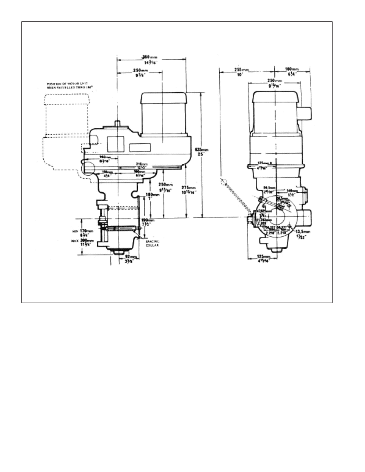
TP5268
Figure 5.3 - 2J-Head Specifications
ENGLISH METRIC
Spindle Taper R8 R8
Spindle Speeds – RPM 60-4200 60-4200
Motor *2 HP 1.5 kw
Quill Travel 5” 127mm
Power Feed of Quill .0015” .04mm
per Rev of Spindle (3 Rates) .003” .08mm
.006” .15mm
Collet Capacity .125” – .750” x .063” 3 – 19mm x 1.5mm
Weight 196 lb. 89 kg
*2 HP Continuous – 3 HP Intermittent
5-6 M-508
Page 87

- NOTES -
M-508 5-7
Page 88

 Loading...