

Hardinge 16C Mounting Instructions
MOUNTING INSTRUCTIONS
and
PARTS LIST
for
16C
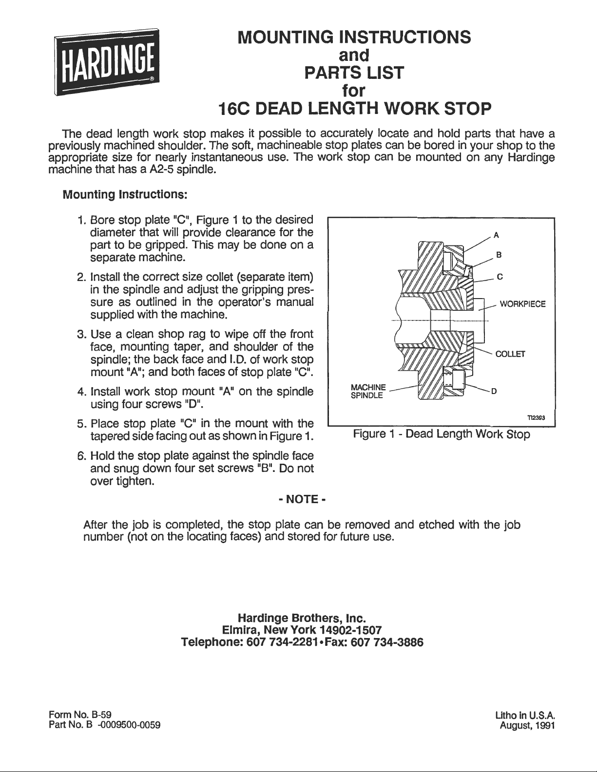
The dead length work stop makes it possible to accurately locate and hold parts that have a
previously machined shoulder. The soft, machineable stop plates can be bored in your shop to the
appropriate size for nearly instantaneous use. The work stop can be mounted on any Hardinge
machine that has a
A2-5
spindle.
DEAD LENGTH WORK STOP
Mounting Instructions:
1.
Bore stop plate "C", Figure 1 to the desired
diameter that will provide clearance for the
part to be gripped. This may be done on a
separate machine.
2.
Install the correct size collet (separate item)
in the spindle and adjust the gripping pressure as outlined in the operator's manual
supplied with the machine.
3.
Use a clean shop rag to wipe off the front
face, mounting taper, and shoulder of the
spindle; the back face and I.D. of work stop
"A";
mount
4.
Install work stop mount
using four screws
and both faces of stop plate "C".
"A"
on the spindle
"DM.
MACHINE
SPINDLE
-
COLLET
D
5.
Place stop plate "C"
tapered side facing out as shown in Figure
6.
Hold the stop plate against the spindle face
and snug down four set screws
over tighten.
After the job is completed, the stop plate can be removed and etched with the job
number (not on the locating faces) and stored for future use.
in
the mount with the
Hardinge Brothers,
Elmira,
Telephone:
1.
"B".
Do not
-
NOTE
New
York
607 734-2281
Figure
=
Inc.
14902-1 507
@Fax:
607 734-3886
1
-
Dead Length Work Stop
Form No. B-59
Part
No. B -0009500-0059
in
Litho
August, 1991
U.S.A.
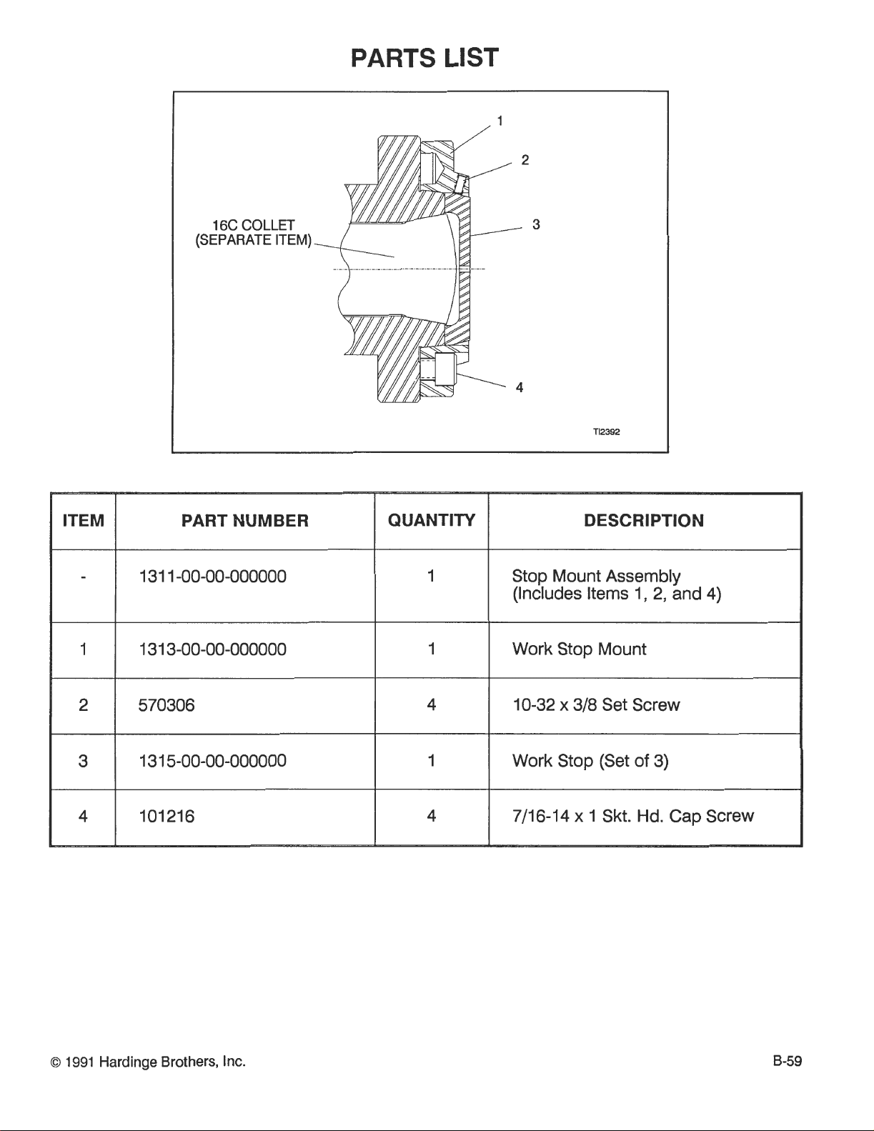
16C
(SEPARATE ITEM)
COLLET
PARTS LIST
ITEM PART NUMBER
QUANTITY
DESCRIPTION
Stop Mount Assembly
I,
2,
(Includes Items
and
Work Stop Mount
10-32 x 318
Work Stop (Set of
7/16-14
Set Screw
3)
x
1
Skt. Hd. Cap Screw
4)
O
1991 Hardinge Brothers, Inc.
 Loading...