

Page 1
ZENIT
Original
Instruction book
67025002-200 - Version 2.00
GB - 09.2015
www.hardi.es
www.hardi-international.com
Page 2

Page 3

Congratulations for choosing a HARDI crop protection product. The reliability and efficiency
of this machine depends entirely on the care it receives. The first step is to carefully read and
pay attention to this instruction book. It contains essential information on correctly using and
ensuring a long useful life of this quality product.
As this instruction book includes all versions of the equipment, including all the different hydraulic boom and operating unit versions, please pay particular attention to the paragraphs
dealing with your specific model.
This book should be read in conjunction with the ‘Spraying Techniques’ booklet
The original instruction book is approved and published in English. All other languages are translations of the original. In the event of any conflicts, inaccuracies or deviations between the English
original and other languages the English version shall prevail.
Since it is ILEMO-HARDI S.A.U. policy to continually improve our products, we reserve the right to
make changes in the design, accessories, specifications and maintenance instructions at any time
and without notice.
ILEMO-HARDI S.A.U. is exenpt from any obligation regarding instruments purchased before or after such changes. ILEMO-HARDI S.A.U. cannot undertake any responsibility for possible omissions
or inaccuracies in this publication, although it has done everything in its power to make this information as complete and correct as possible.
As this instruction book covers models, specifications or equipment that are only available in certain countries, please pay particular attention to the paragraphs dealing with your specific model.
Published and printed by ILEMO-HARDI S.A.U.
Page 4

Page 5

Table of Contents
1 - EC Declaration
EC Declaration of Conformity .............................................................................................................. 5
2 - Safety
Operator safety ................................................................................................................................... 7
Symbols .................................................................................................................................................................................................................................................................7
Precautions ..........................................................................................................................................................................................................................................................7
3 - Description
General information ............................................................................................................................ 9
Overview .............................................................................................................................................................................................................................................................. 9
Use of the mistblower ............................................................................................................................................................................................................................... 10
Roadworthiness ............................................................................................................................................................................................................................................ 10
Use of the mist blower .............................................................................................................................................................................................................................. 11
Roadworthiness ............................................................................................................................................................................................................................................ 11
Identification plate ...................................................................................................................................................................................................................................... 11
Chassis ................................................................................................................................................................................................................................................................. 11
Tank .......................................................................................................................................................................................................................................................................12
Liquid system .................................................................................................................................... 13
General information ................................................................................................................................................................................................................................... 13
The liquid circuit ...........................................................................................................................................................................................................................................13
Diaphragm pump ........................................................................................................................................................................................................................................ 13
Valves ...................................................................................................................................................................................................................................................................13
Valves and symbols .....................................................................................................................................................................................................................................13
Manifold system ............................................................................................................................................................................................................................................ 14
Safety valves .................................................................................................................................................................................................................................................... 14
Blue valve – Blue disc = Return valve .............................................................................................................................................................................................. 14
Pressure pulsation damper.....................................................................................................................................................................................................................14
Circuit Diagram .............................................................................................................................................................................................................................................. 15
Suction filter .................................................................................................................................................................................................................................................... 15
Safety valve.......................................................................................................................................................................................................................................................16
Pressure manifold .........................................................................................................................................................................................................................................16
Suction and pressure pulsation dampers ..................................................................................................................................................................................... 16
Agitator ...............................................................................................................................................................................................................................................................16
Operating unit ................................................................................................................................................................................................................................................ 17
MC/2 operating unit ................................................................................................................................................................................................................................... 17
SV operating unit .......................................................................................................................................................................................................................................... 17
CB operating unit ......................................................................................................................................................................................................................................... 17
Filters ....................................................................................................................................................................................................................................................................17
Powder mixer ..................................................................................................................................................................................................................................................17
TurboFiller ........................................................................................................................................................................................................................................................18
Axial blower units ............................................................................................................................. 19
Technical information ................................................................................................................................................................................................................................ 19
EF820, EF920, AB750, AB820, AB920, AG820 and AG920 ..................................................................................................................................................... 19
Aif flow for axial air kits ..............................................................................................................................................................................................................................21
Deflectors .......................................................................................................................................................................................................................................................... 22
Gearbox .............................................................................................................................................................................................................................................................. 22
Fan ......................................................................................................................................................................................................................................................................... 22
Adjusting the fan .......................................................................................................................................................................................................................................... 23
Centrifugal Blower Units ................................................................................................................... 24
General information ................................................................................................................................................................................................................................... 24
HF540 (TS3 P540 / TS6 P540 Single)...............................................................................................................................................................................................24
HF540D (TD3-P540 Double) ............................................................................................................................................................................................................... 24
HF640D (TD3-P640 Double) .............................................................................................................................................................................................................. 24
Protective grid ................................................................................................................................................................................................................................................25
Gearbox .............................................................................................................................................................................................................................................................. 26
HF540, HF540D and HF 640D Turbine.............................................................................................................................................................................................26
Clutch (All blower types) ......................................................................................................................................................................................................................... 26
Light kit ............................................................................................................................................................................................................................................................... 27
Booms..................................................................................................................................................................................................................................................................27
The LINER boom ......................................................................................................................................................................................................................................... 27
The ATLAS boom .......................................................................................................................................................................................................................................... 28
The BOXER boom .........................................................................................................................................................................................................................................29
1
Page 6

Table of Contents
The CRONOS boom .................................................................................................................................................................................................................................... 30
Variant boom ..................................................................................................................................................................................................................................................31
Break away clutch ........................................................................................................................................................................................................................................32
Particulairly for CRONOS boom ........................................................................................................................................................................................................... 32
Pneumatic spray system ..........................................................................................................................................................................................................................33
Hydropneumatic spray system ............................................................................................................................................................................................................ 33
IRIS system, continuation of Hydro pneumatic system ......................................................................................................................................................34
4 - Starting up
General information .......................................................................................................................... 35
Unloading the mistblower from the truck ...................................................................................................................................................................................35
Before starting up for the first time ................................................................................................................................................................................................... 35
Counterweights ............................................................................................................................................................................................................................................ 35
Coupling the driveshaft............................................................................................................................................................................................................................36
Hooking up the mistblower .................................................................................................................................................................................................................. 37
Hydraulic connections ....................................................................................................................... 38
General information ................................................................................................................................................................................................................................... 38
Tractor requirements ..................................................................................................................................................................................................................................38
Electrical connections ....................................................................................................................... 39
General information ................................................................................................................................................................................................................................... 39
Electrical operating units .........................................................................................................................................................................................................................39
Rate controller................................................................................................................................... 40
Rate controller DB 3610 ............................................................................................................................................................................................................................40
Rate controller DB 3620 ............................................................................................................................................................................................................................41
Fluid circuit ....................................................................................................................................... 42
Suction filter .................................................................................................................................................................................................................................................... 42
Pressure damper ...........................................................................................................................................................................................................................................42
Diaphragm pump ........................................................................................................................................................................................................................................ 42
Deflectors .......................................................................................................................................................................................................................................................... 43
Booms ............................................................................................................................................... 45
General information ................................................................................................................................................................................................................................... 45
FIX .......................................................................................................................................................................................................................................................................... 45
START ................................................................................................................................................................................................................................................................... 45
ATLAS START ....................................................................................................................................................................................................................................................46
ATLAS AGILE .....................................................................................................................................................................................................................................................46
ATLAS SOLID FIX and ATLAS SOLID FIX GV..................................................................................................................................................................................46
ATLAS SOLID CONVERT and ATLAS SOLID GV CONVERT ..................................................................................................................................................... 46
BOXER START ................................................................................................................................................................................................................................................... 47
BOXER SOLID VERTICAL FIX or CONVERT .....................................................................................................................................................................................47
BOXER SOLID HORIZONTAL ...................................................................................................................................................................................................................47
Adjustment of BOXER boom .................................................................................................................................................................................................................48
CRONOS BOOM ............................................................................................................................................................................................................................................. 48
SOLID ................................................................................................................................................................................................................................................................... 48
RIDER .................................................................................................................................................................................................................................................................... 49
VARIA ....................................................................................................................................................................................................................................................................49
CRONOS GV .................................................................................................................................................................................................................................................... 49
General for all boom models ................................................................................................................................................................................................................ 50
Break away clutch .......................................................................................................................................................................................................................................50
Adjustment of hydraulic fold ................................................................................................................................................................................................................50
Transport bracket ........................................................................................................................................................................................................................................ 51
Adjustment of upright ............................................................................................................................................................................................................................. 51
Adjustment of out spray device .......................................................................................................................................................................................................... 51
The hydraulic version .................................................................................................................................................................................................................................52
Adjustment of inner 4 spray device .................................................................................................................................................................................................. 52
Hydraulic adjustment of the Convert brackets ........................................................................................................................................................................ 53
IRIS system setup .......................................................................................................................................................................................................................................... 53
Cannons ............................................................................................................................................................................................................................................................. 54
Calibration.........................................................................................................................................................................................................................................................54
5 - Operation
Blower unit ........................................................................................................................................ 55
Safety information ....................................................................................................................................................................................................................................... 55
Selecting the gear ........................................................................................................................................................................................................................................55
2
Page 7

Table of Contents
While moving the Sprayer ...................................................................................................................................................................................................................... 56
Adjusting the fan AB820 .......................................................................................................................................................................................................................... 57
Single side blinds (Optional) ................................................................................................................................................................................................................. 57
Liquid and air circuits ........................................................................................................................ 58
Filling/washing location requirements ...........................................................................................................................................................................................58
Suction Filter ....................................................................................................................................................................................................................................................58
Filling/washing location requirements ...........................................................................................................................................................................................59
Filling with water ..........................................................................................................................................................................................................................................59
Draining the main tank ............................................................................................................................................................................................................................. 59
Pressure filters .................................................................................................................................................................................................................................................60
Agitation ............................................................................................................................................................................................................................................................ 60
Clean water tank ........................................................................................................................................................................................................................................... 60
Powder mixer ..................................................................................................................................................................................................................................................60
Filling through tank lid ..............................................................................................................................................................................................................................61
Filling the rinsing tank ...............................................................................................................................................................................................................................61
Rinsing nozzle .................................................................................................................................................................................................................................................62
Unexpected interruptions ...................................................................................................................................................................................................................... 62
Filling the clean water tank ....................................................................................................................................................................................................................62
Drain valve ........................................................................................................................................................................................................................................................ 62
Manifold system ............................................................................................................................................................................................................................................ 63
Filling liquid chemicals by HARDI TurboFiller (optional) ......................................................................................................................................................63
TurboFiller rinsing.........................................................................................................................................................................................................................................64
Power supply...................................................................................................................................................................................................................................................65
Installation of control unit brackets .................................................................................................................................................................................................. 65
SB 3002 or SB 3004 ...................................................................................................................................................................................................................................... 66
SV operating unit .......................................................................................................................................................................................................................................... 66
SB 3012 or SB 3014 etc. ............................................................................................................................................................................................................................. 66
CA operating unit .........................................................................................................................................................................................................................................67
SB 3012 or SB 3014 etc. ............................................................................................................................................................................................................................. 67
FB 3610 ............................................................................................................................................................................................................................................................... 67
CB operating unit ......................................................................................................................................................................................................................................... 68
CB operating unit with by pass valve .............................................................................................................................................................................................. 68
Hydraulic control boxes ..........................................................................................................................................................................................................................68
HB 3610 .............................................................................................................................................................................................................................................................. 69
The Joystick S selector ............................................................................................................................................................................................................................. 69
Cannon L-M-T .................................................................................................................................................................................................................................................69
Hydraulic control of the CANNON ................................................................................................................................................................................................... 70
The spout can be rotated180º by another double acting outlet. This allows treatment to either side independet of driving
direction. ............................................................................................................................................................................................................................................................ 70
The hydraulic adjustment ......................................................................................................................................................................................................................70
HC 3100 control box ................................................................................................................................................................................................................................. 71
Vegetation sensor is optionally equipped ....................................................................................................................................................................................71
Rate controller DB3610 and DB3620 ...........................................................................................................................................................................................72
Adjusting the BK/2 Operating Unit ................................................................................................................................................................................................... 74
MC/2 operating unit ................................................................................................................................................................................................................................... 74
Cleaning ............................................................................................................................................ 75
General information ................................................................................................................................................................................................................................... 75
Cleaning and maintaining the filters ............................................................................................................................................................................................... 75
Filling/washing location requirements ...........................................................................................................................................................................................76
Suction Filter ....................................................................................................................................................................................................................................................76
Nozzles ................................................................................................................................................................................................................................................................ 77
Cleaning the tank and liquid system ............................................................................................................................................................................................... 77
Use of rinsing tank and rinsing nozzles (optional) ...................................................................................................................................................................78
6 - Maintenance
Lubrication ........................................................................................................................................ 80
General information ................................................................................................................................................................................................................................... 80
Recommended lubricants ...................................................................................................................................................................................................................... 80
Lubricating and greasing the mistblower ....................................................................................................................................................................................80
Variant boom ..................................................................................................................................................................................................................................................82
Transmission shaft .......................................................................................................................................................................................................................................83
Mechanical clutch ........................................................................................................................................................................................................................................ 83
Diaphragm pump ........................................................................................................................................................................................................................................ 83
3
Page 8

Table of Contents
Filters and fittings .........................................................................................................................................................................................................................................84
Winter storage ................................................................................................................................................................................................................................................84
Preparing the equipment for use after storage .........................................................................................................................................................................84
Service and maintenance intervals ................................................................................................... 85
General information ................................................................................................................................................................................................................................... 85
Every 10 working hours – Spray circuit .......................................................................................................................................................................................... 85
Every 50 working hours – Transmission shaft, chassis, air pressure and diaphragm pump .........................................................................85
Every 100 working hours – Drawbar ................................................................................................................................................................................................ 85
Every 250 working hours – Wheels, brakes, hoses and gearbox .................................................................................................................................... 85
Every 1000 working hours – Full service ........................................................................................................................................................................................ 85
Regular maintenance ........................................................................................................................ 86
Every 10 working hours – Suction filter ......................................................................................................................................................................................... 86
Every 10 hours of operation – Pressure filters ............................................................................................................................................................................86
Every 10 working hours – Nozzles ..................................................................................................................................................................................................... 87
Every 1000 working hours - Gearbox oil change ..................................................................................................................................................................... 87
Every 1000 working hours - Fan clutch inspection ................................................................................................................................................................. 88
Every 1000 working hours - Fan transmission shaft inspection ...................................................................................................................................... 88
Occasional maintenance ................................................................................................................... 89
Replacing the 321 valves and diaphragms .................................................................................................................................................................................. 89
SV operating unit .......................................................................................................................................................................................................................................... 89
CB Section valve ............................................................................................................................................................................................................................................ 90
Cleaning the air kit ..................................................................................................................................................................................................................................... 92
Tank level indicator adjustment ..........................................................................................................................................................................................................93
Replacing the valves and 363 and 463 diaphragms .............................................................................................................................................................. 93
Lubrication ........................................................................................................................................ 94
General information ................................................................................................................................................................................................................................... 94
Grease Gun Calibration ............................................................................................................................................................................................................................. 95
Greasing the Pump .....................................................................................................................................................................................................................................95
Service and Maintenance Intervals ................................................................................................... 96
50 Hours Service - Greasing the Pump ........................................................................................................................................................................................... 96
Occasional Maintenance ................................................................................................................... 97
Lifting and Removing the Pump ........................................................................................................................................................................................................ 97
Pump Valves and Diaphragms Renewal ........................................................................................................................................................................................ 97
Adjusting the 3-way valve ......................................................................................................................................................................................................................99
Replacing the driveshaft protector guard .................................................................................................................................................................................... 99
Replacing the driveshaft crossheads ............................................................................................................................................................................................... 99
Replacing the seal on the drain valve...........................................................................................................................................................................................100
Storing the mistblower at the end of the season ................................................................................................................................................................. 100
Preparing the machine for use after storage ........................................................................................................................................................................... 101
7 - Troubleshooting
Operational problems ..................................................................................................................... 102
General information ................................................................................................................................................................................................................................ 102
Fluid circuit .................................................................................................................................................................................................................................................... 103
Blower unit .................................................................................................................................................................................................................................................... 104
Electrical problems ......................................................................................................................... 105
Emergency function – Fluid circuit ................................................................................................................................................................................................ 105
8 - Technical specifications
Dimensions ..................................................................................................................................... 106
Zenit Axial ...................................................................................................................................................................................................................................................... 106
Zenit Liner ...................................................................................................................................................................................................................................................... 106
Conversion factors (SI to Imperial) .................................................................................................................................................................................................. 107
Pump model 363/7 .................................................................................................................................................................................................................................. 107
Pump model 321/10 ............................................................................................................................................................................................................................... 107
Specifications .................................................................................................................................. 108
321/7 and 321/10 Diaphragm ........................................................................................................................................................................................................... 108
363/7 Diaphragm ...................................................................................................................................................................................................................................... 109
Filters and nozzles ..................................................................................................................................................................................................................................... 109
Temperature and pressure range .................................................................................................................................................................................................... 109
Materials and recycling ................................................................................................................... 110
Disposing of the mistblower ..............................................................................................................................................................................................................110
Index
4
Page 9

EC Declaration of Conformity
Manufacturer:
ILEMO HARDI S.A.U.
Poligono El Segre, 712, 713
25080 Lleida
SPAIN
Declares the following product(s):
1 - EC Declaration
NEPTUN
ZATURN
JUPITER
- hare manufactured in conformity with the applicable provisions of the Directive 2006/42/EC on machinery, and
- all the applicable provisions of the Council Directive 2004/108/EC (EMC)
Lleida, March 2015
Josep Maria Godia
Technical Director
ILEMO HARDI S.A.U.
5
Page 10

6
Page 11

2 - Safety
Operator safety
Symbols
These symbols are used in the book and require special attention. The meaning of the four symbols is:
This symbol means DANGER. Be alert as your safety is involved!
This symbol means WARNING. Be alert as your safety may be involved!
This symbol means ATTENTION. This will guide you on how to correctly and safely use the sprayer equipment.
This symbol means NOTE.
Precautions
Please note these precautions and safe operating practices before using the sprayer.
General information
Read and fully understand this instruction book before using the equipment. It is also equally important that
other operators of the equipment read and understand this book.
If you do not fully understand any part of this instruction book after reading it, please contact your HARDI
distributor for further information before using the equipment.
Local law may demand the operator to be certified to use this spray equipment. Comply with the law.
The tractor seat is the safest area when handling the equipment.
Wear protective clothing. Protective clothing may vary according to the chemical product being used. Comply
with regulations.
Wash and change clothes after spraying. Clean the tools if they have become contaminated.
Do not eat, drink or smoke while spraying or working with contaminated equipment.
In the event of poisoning, immediately seek medical advice. Remember to identify the chemicals used.
Filling and spraying
Be careful not to hit persons or objects while manoeuvring the spraying equipment, especially when reversing.
Slow down when driving over uneven terrain as the machine could overturn.
Keep children away from the sprayer.
Do not attempt to enter the tank.
Do not climb over the sprayer unless it has been securely fastened. The boom is only secure when it is placed in
the transport brackets.
7
Page 12

2 - Safety
Service
Always pressure test with clean water before filling with chemicals. Do not remove the hose if the machine is
turned on.
DANGER! Do not exceed the maximum recommended r.p.m.
Rinse and wash out the equipment after use and before servicing.
Do not remove the hose if the machine is turned on. Always replace all safety devices or shields immediately after
servicing.
Disconnect the power supply before servicing, and de-pressurise the equipment after use and servicing.
If an arc welder is used on the equipment, disconnect any power leads before welding.
Remove all inflammable or explosive materials from the area.
The External Cleaning Device should not be used if any part of the equipment has been damaged, including
safety devices, high-pressure hoses, etc.
8
Page 13
General information
Overview
1
2
3
3 - Description
12
4
5
6
7
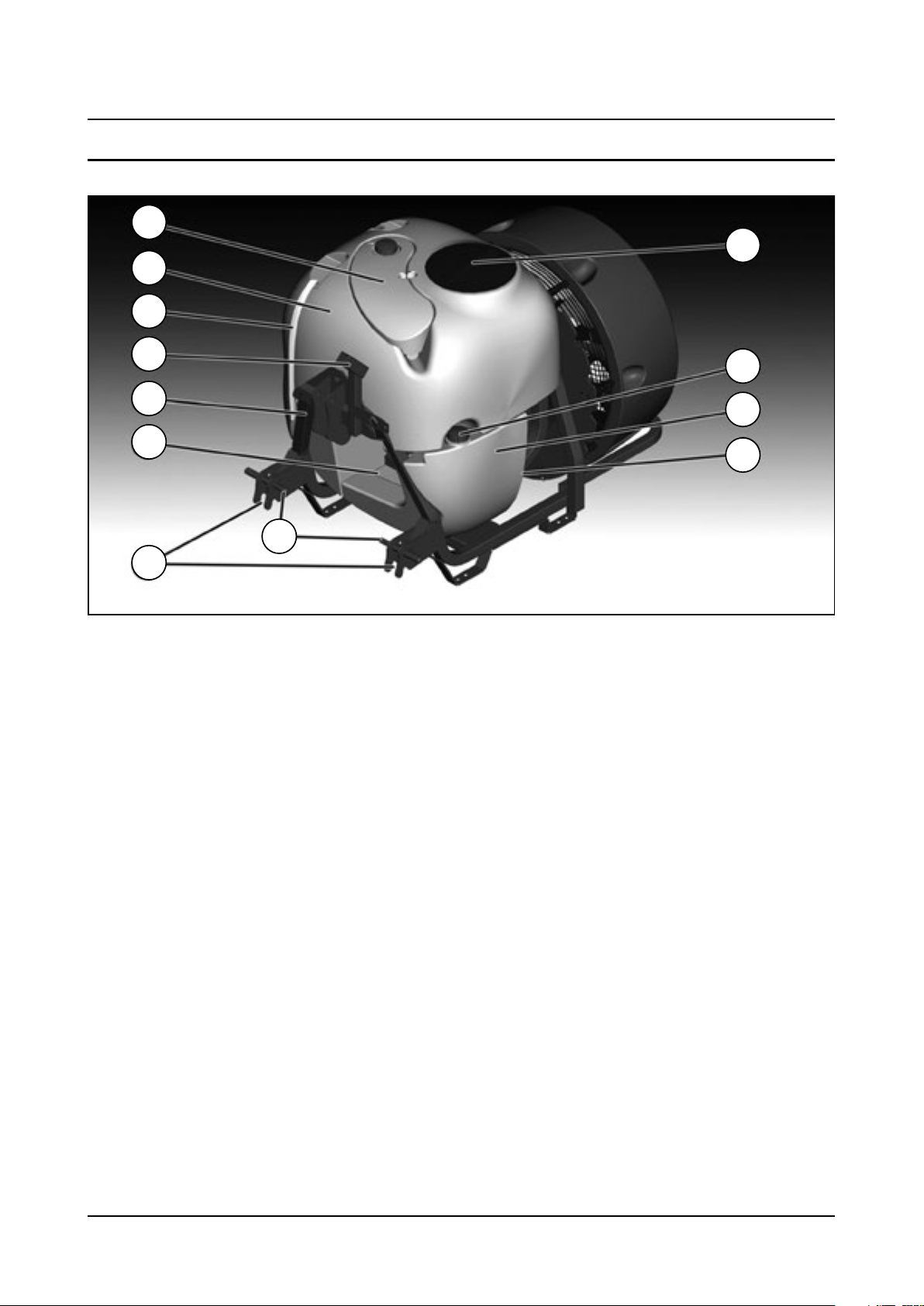
1. Clean water tank
2. Main tank
3. Front level indicator
4. Operating Unit
5. 3-point hitch
6. Pump
11
10
9
8
7. Quick hitch
8. Attachment, lift arms
9. Suction filter
10. Rinse tank
11. Rinse tank cap
12. Main tank lid
9
Page 14
3 - Description
13
14
15
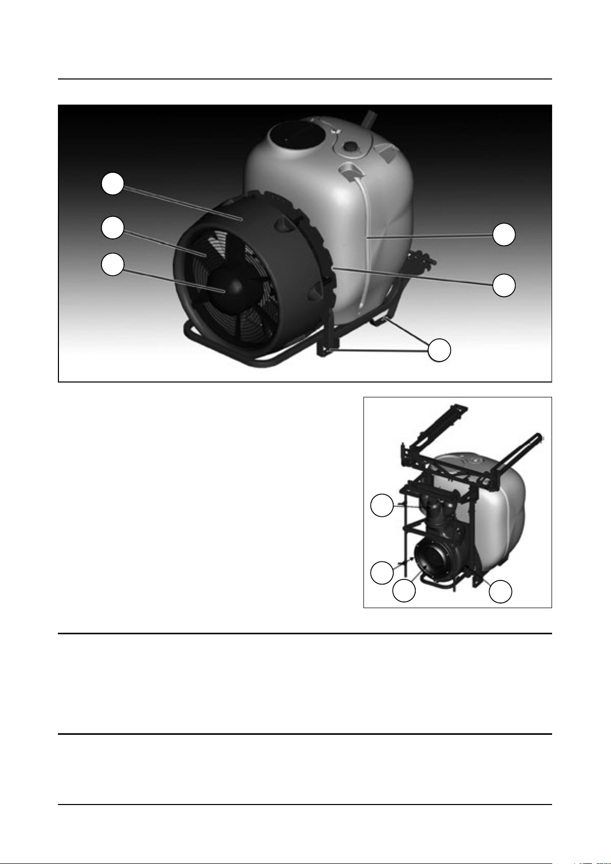
13. Polyethylene fan housing
14. Air inlet grid
15. Fan
16. Support legs
17. Air outlet grid
18. Side level indicator
The illustrations are covering axial and turbine machines, both can
be equipped with optional extras, that might be or not be illustrated.
The turbine machine is either equipped with vine boom or a cannon
spout, as well as the axial machines might be equipped with deflectors.
More detail described further ahead in this chapter, and the following.
18
17
16
17
14
15
Use of the mistblower
The HARDI mistblower is designed for applying crop protection chemicals. The equipment should only be used for this
purpose. The mistblower must not be used for any other purpose. If there is no special regulations requiring operators to
be certified, you must have received the appropriate training for correctly spraying crops and safely handling chemicals
to avoid unnecessary risks to persons and the environment while spraying.
Roadworthiness
When driving on public roads and other places where the road safety code or where there are other special rules and
regulations for marking and lights on machinery, the machine must be equipped to comply with these regulations.
10
13
Page 15
3 - Description
Use of the mist blower
The HARDI mist blower is designed for applying chemical products used for crop protection. This equipment may only
be used for this purpose. The use of this equipment for other purposes is not allowed. If there is no special law in your
region which obliges the user to have a permit, it is recommended to be well-prepared for protecting crops in a correct
way and for handling chemical products safely so as to avoid unnecessary risks to people and the environment while
spraying takes place.
For environmental issues the air kit is offered with option to close either left or right side of the air stream from the
blower. These blinds, are mandatory in some sensitive areas, to avoid chemical contaminated air, blowing towards river
sides and water channels
Roadworthiness
When driving on public roads and other places where the road safety code or where there are other special rules and
regulations for marking and lights on machinery, the machine must be equipped to comply with these regulations.
ATTENTION! For models not fitted with brakes the maximum speed is 25 km/h and 40 km/h for those with. This
could vary according to local legislation. Contact your local authorities to find out the current maximum speed
limits.
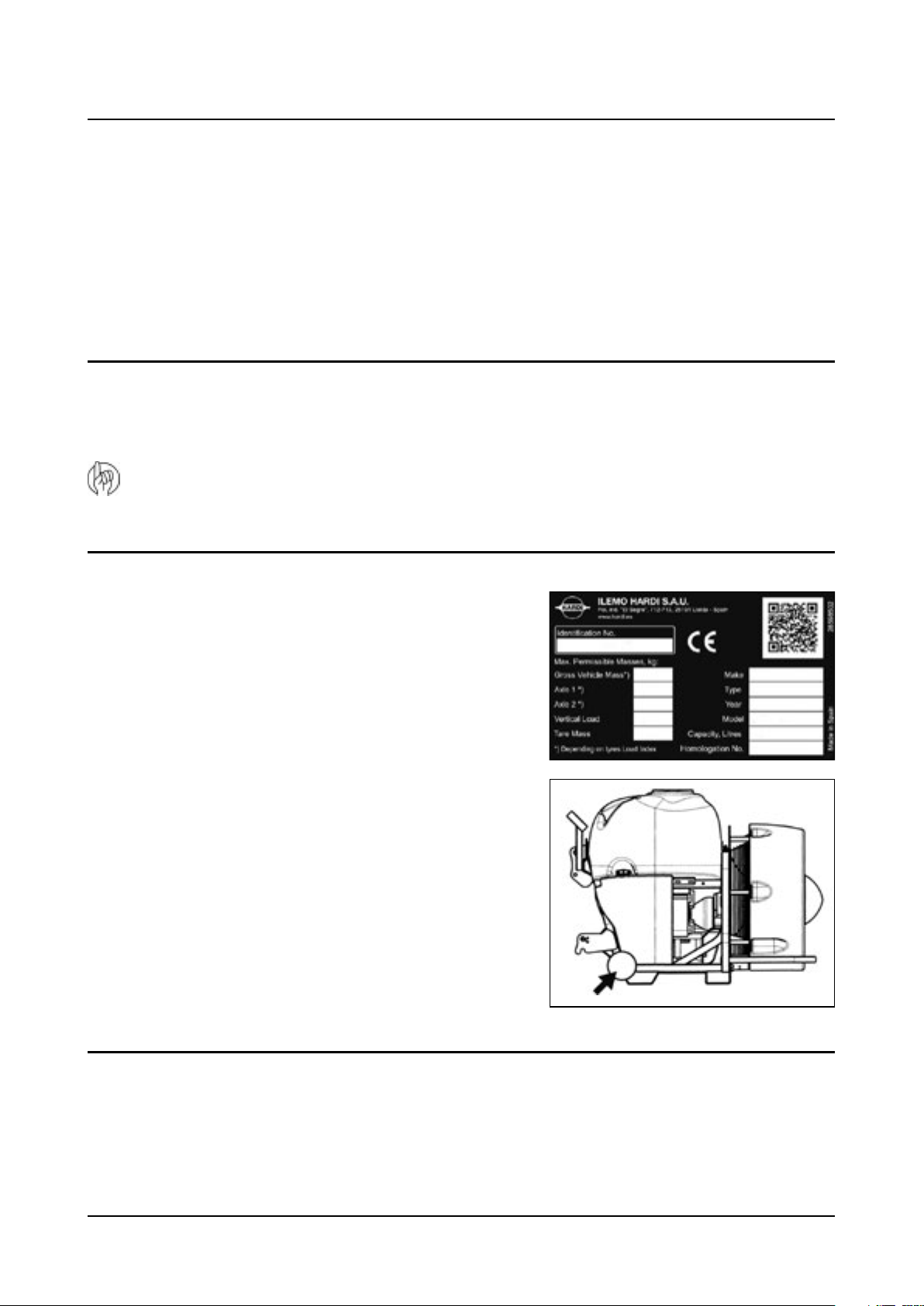
Identification plate
The identification plate is located on the front right-hand side of the
machine and is riveted to the chassis. It indicates the make, model,
serial number, and date of manufacture.
The serial number is also engraved onto the chassis. The number is
found above the identification plate, as indicated in the picture. The
serial number consist of five digits.
Chassis
The monoblock cold-pressed metal chassis is highly durable and built to last under everyday use under extreme
conditions. It is manufactured using only the most advanced laser cutting and automated soldering processes. To protect
against corrosion it is coated with a polyurethane bi-component paint on top of a highly adherent, steel blasted base.
11
Page 16

3 - Description
Tank
The main tank made of impact-proof, UV-resistant and chemical resistant polyethylene, has a purposeful design with
no sharp corners for easy cleaning. Nominal contents are1000, 1500, 2000 or 3000 l. A large, easy to read tank contents
indicator is placed on the front - right-hand side and another one is placed on the left side. First one is visible from the
tractor cabin. The filling hole is accessible from the left-hand side. This ensures an easy access for the filling of spray liquid,
cleaning of the tank, etc. The mistblower is equipped with a clean water tank integrated with the main tank design.
12
Page 17
3 - Description
Liquid system
General information
All the suction system functions are operated via a 3-way valve. The pressure valve is also to be found in the pressure
circuit. The low pressure circuit is called HLC (Hardi Liquid Circuit).
The liquid circuit
Consists of a manifold system in the working zone (front part) where pressure manifold receives liquid from the pump,
and distributes to the different options on the sprayer: to the operating unit, to the TurboFiller, to the bottle cleaner, to
the Powder mixer in strainer etc., all according to configuration of options. The suction manifold in same area allows
suction from main tank, rinsing tank or external water source, if fitted, depending on the configuration.
The pressure side of the liquid circuit is fitted with a safety valve to protect the circuit against misuse of excessive
pressure. See chapter “Safety valve”
Diaphragm pump
Pumps with a diaphragm: Models 321/10 (max. 20 bar) or 363/7 (max. 20 bar)
They are low pressure and robustly built. Use only grease for lubrication. The 363 model has six diaphragms and the 321
has two. This type of pump is self-priming, works without oil and can run dry as long as necessary.
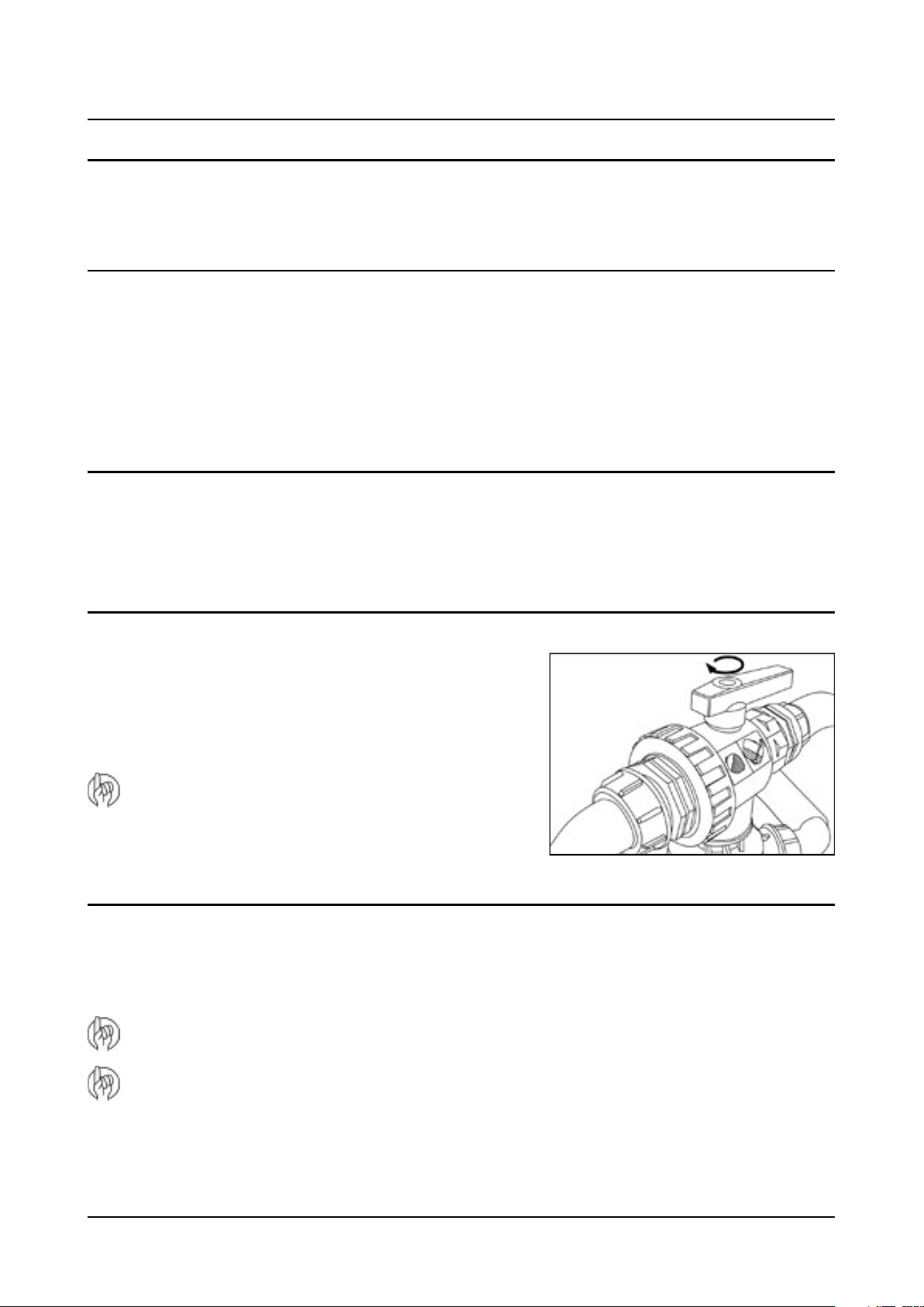
Valves
The suction valve is located above the pump and is used to select
where to suck liquid from. Either suction from the main tank for
spraying or from the rinse tank for internal cleaning of the liquid circuit.
The function is selected by turning the handle of the valve towards the
desired function.
ATTENTION! If one of the handles is too tight - or too loose
(= liquid loss) - the valve needs to be serviced. For more
information, see section on “Maintenance”.
Valves and symbols
The valves are identified by coloured discs fitted on the valves themselves. The symbols correspond to the optional
accessories, and are located on the discs for quick identification and handling. To activate/open a function, turn the lever
to the desired function.
ATTENTION: Only the functions to be used should be activated – the other valves should always be kept closed.
ATTENTION: If the handle of a MANIFOLD valve is too tight – or too loose (loss of fluid)– the valve needs to be
serviced. For more information, see the section on ‘Maintenance’.
13
Page 18
3 - Description
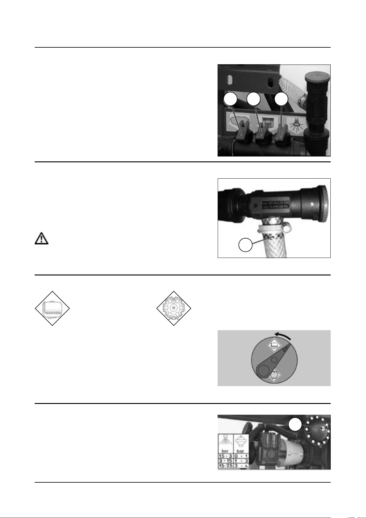
Manifold system
The pressure circuit HLC (Hardi Liquid Circuit) is used with diaphragm
pumps. The HLC distributor has three mechanical valves.
Valve (A) operates the agitator.
Valve (B) activates the powder mixer which flushes powder chemicals
through the tank strainer.
Valve (C) activates the rotating rinsing nozzle for rinsing the main tank
inside when the liquid circuit is rinsed with clean water.
Each function is identified by a pictorial symbol. Valves (A) and (B) are
optional.
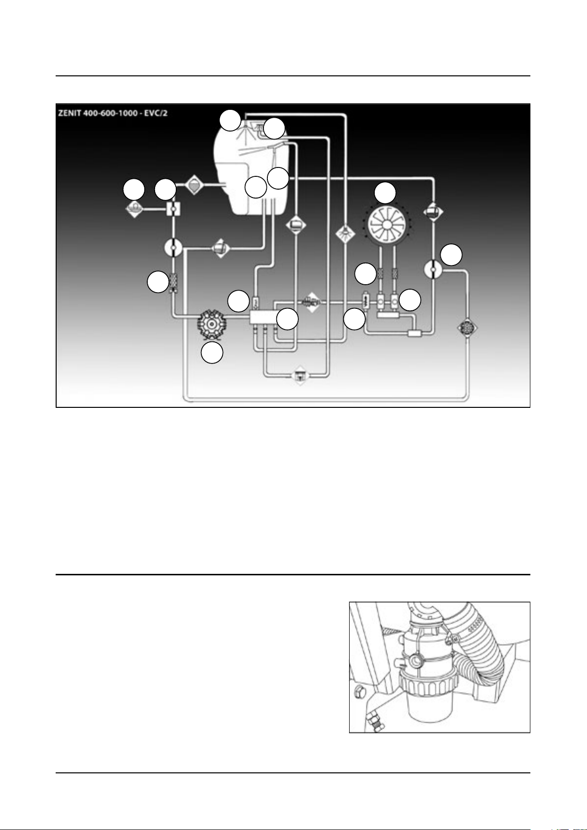
Safety valves
The safety valve protects the liquid circuit against over pressure in the
event of failures or clogged lines.
If the spring-loaded safety valve opens the liquid is lead back to tank
via hose (A).
The safety valve opens at15 bar.
DANGER! Do not remove, bypass or block safety valve from the
liquid circuit as this could put your safety at risk.
A B C
A
Blue valve – Blue disc = Return valve
Towards agitation Towards the suction pump
The position of the return MANIFOLD valve determines where the
excess flow from the fluid circuit goes. When the arrow on the handle
points to a symbol, the excess fluid will be fully sent towards that
function (the example shows agitation). This valve does not have the ‘0’
position.
Pressure pulsation damper
The 321 pump is fitted with a pulsation damper on suction and
pressure sides. The pressure side damper is pressureized. The dampers
will reduce pulsations and secure an even flow from the pump.
The pressuredamper should be inflatedto the pressure shown in the
table on top of the pulsation damper (A).
A
14
Page 19
Circuit Diagram
3 - Description
13
12
8
5
2
1
11
14
10
3
6
9
7 15
4
1. Main tank
2. Suction MANIFOLD (black)
3. Suction filter
4. Pump
5. External filling
6. Safety valve
7. Pressure collector
8. Agitation
Circuit configuration can vary according to local legislation and standards, e.g. dump valve.
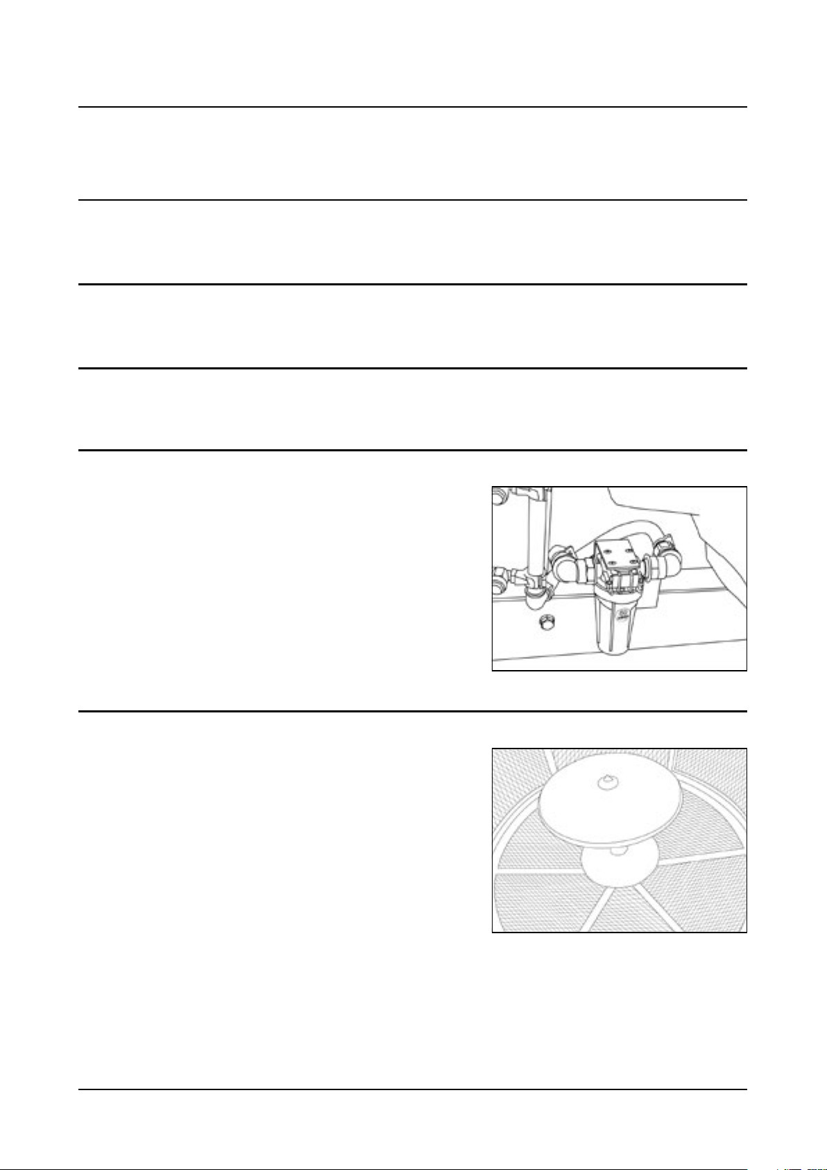
Suction filter
The suction filter is located underneath the three-way suction valve.
9. Section valves
10. Pressure filters
11. Fan and nozzles
12. Powder mixer
13. Nozzle for internal cleaning
14. Return Manifold (Blue)
15. Pressure regulator
15
Page 20
3 - Description
Safety valve
It is made of cast iron and is situated on the front of the machine
next to the operating unit. From this manifold it is possible to activate
the agitator and the rinsing nozzle for internal cleaning (optional),
as well as the Turbofiller (optional) or powder mixer. Do only open
the manifold valve in order do sent pressure to the desired device, as
example given the Turbofiller.
Pressure manifold
It is made of plastic and is situated on the front of the machine next
to the operating unit. From this manifold it is possible to activate the
agitator and the rinsing nozzle for internal cleaning (optional).
MAX. 20 bar
(HLC)
MAX. 40 bar
(HPC)
Suction and pressure pulsation dampers
The 321 pump is fitted with a pulsation damper on suction and
pressure sides. The pressure side damper is pressureized. The dampers
will reduce pulsations and secure an even flow from the pump.
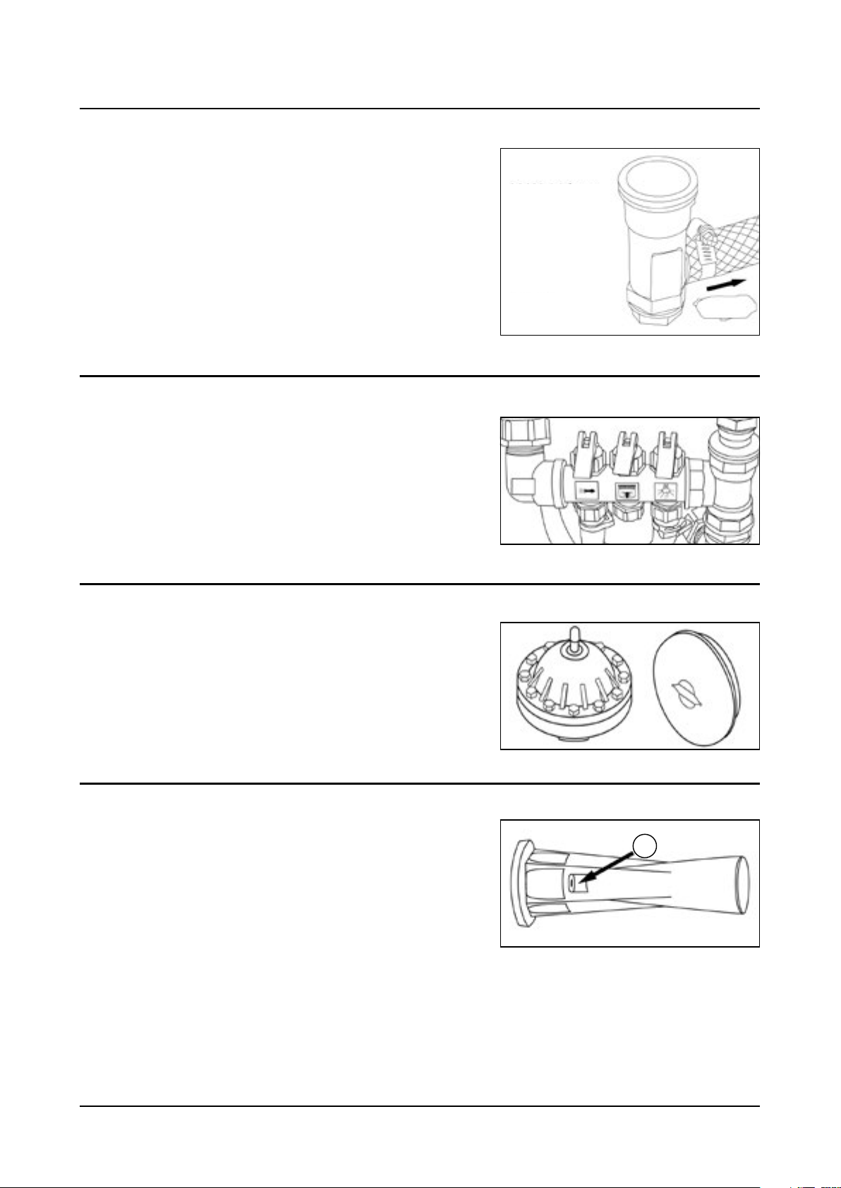
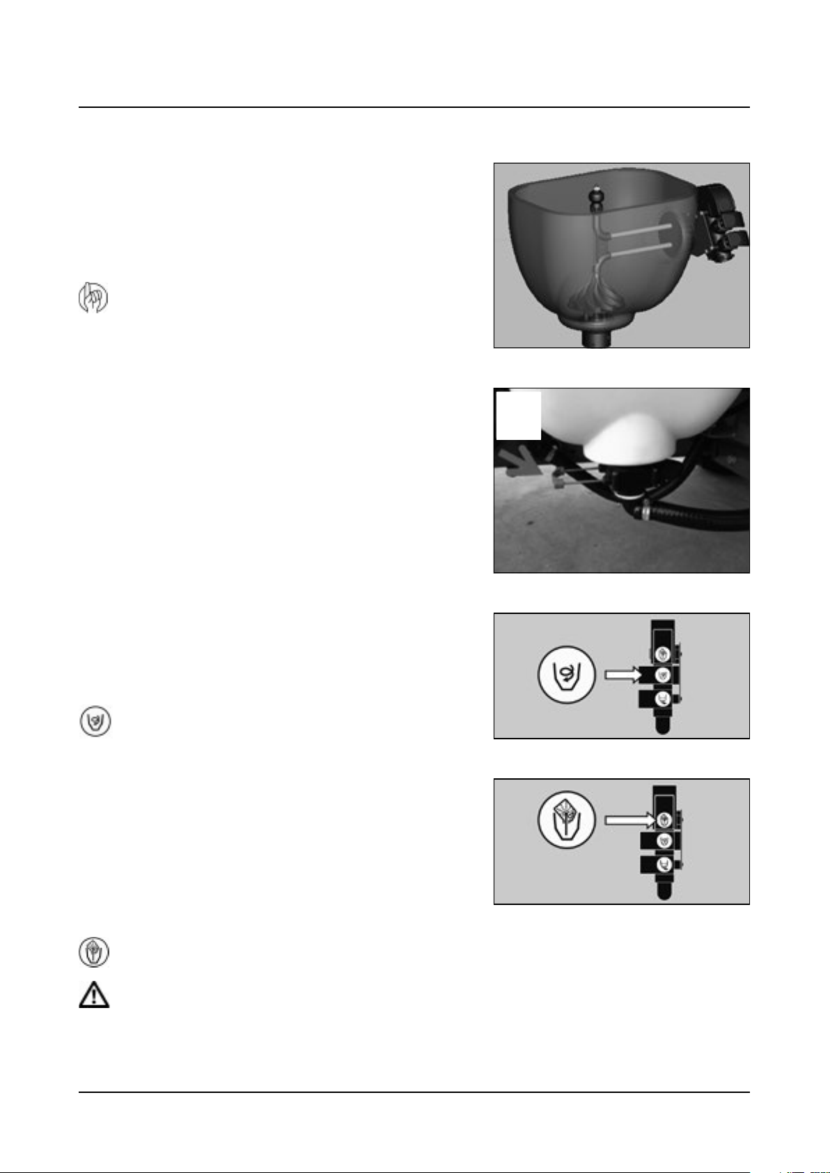
Agitator
At the front and on each side of the inside of the tank there are two
ventury-shaped agitators. The agitators are activated by a valve on the
pressure manifold.
Each agitator has a Ø 3mm nozzle (D).
D
16
Page 21
3 - Description
Operating unit
Your sprayer will be equipped with operating unit accordingly to country specifications.
The mistblower can be equipped with following types of operating units: MC/2, CB/2, SV and CB.
MC/2 operating unit
It has two section valves which control RH and LH sides. The section valves are remote controlled from the tractor cab by
via two bowden cables.
SV operating unit
2 or 4 section valves, by means of solenoid valves for on off of each section. The SV operating unit has no pressure
equalization device. Pressure regulation is done manually in the working zone.
CB operating unit
Electrical remote pressure regulation, section valves by means of motor valves with pressure equalization device.
Filters
The pressure filters are located on the bumper next to the air outlet
nozzle. In the HLC circuit the filters are made of plastic and in the HPC
circuit they are made of brass.
All filters should be kept in good condition and cleaned regularly. Make
sure you to use correct combinations of filter and mesh size. The mesh
size should always be less than the average of the total flow from the
nozzles.
Powder mixer
This is used to rinse the filter basket intank’s filling hole when adding
powdered products that do not dissolve properly form lumps on
contact with the water in the tank.
After using the powder mixer it must be disengaged as it uses a large
amount of the available pump capacity.
17
Page 22
3 - Description
TurboFiller
Chemical inductor, TurboFiller (optional)
The TurboFiller allows filling of both powder and liquid spray chemicals
safe and conveniently when standing next to the machine.
The Turbofiller must be neatly stowed away to the bay under the main
tank when not in use.
ATTENTION! Local legislation may require chemicals to be filled
by use of a chemical inductor. Always follow local legislation
into force at any time.
TurboFiller suction valve
The valve is used simultaneously with the TurboFiller. The valve has 2
settings: In the position A, indicated on the picture, it is closed. Open
the valve when chemicals are to be filled into the TurboFiller.
TurboDeflector valve
This TurboDeflector valve activates the Vortex flushing of the
TurboFiller. Lift the lever to lock it in open position for continuous liquid
rotation in the hopper.
Start TurboDeflector
Chemical Container Rinsing lever
The upper lever is used for two purposes:
A
When the TurboFiller lid is open: For rinsing empty containers. Place
the container over the rotating flushing nozzle in the middle of the
TurboFiller to rinse the inside of the container.
When the TurboFiller lid is closed: Use the Chemical Container Rinsing
lever to rinse the hopper when the filling of chemicals is completed.
Chemical Container Rinsing
DANGER! Do not press the lever unless the multi-hole nozzle is covered by a container as spray liquid may
otherwise hit the operator.
18
Page 23
3 - Description
Axial blower units
Technical information
The air kits fitted on the HARDI ZATURN mist blowers are the AG820 and AG920, both having a polyethylene housing
and fan blades made of a hardened synthetic material. Their aerodynamic shape offer a high quantity and perfect air
distribution, low noise levels and low power consumption when adjusted to standard levels. The fan clutch enables a
smooth start and stop.
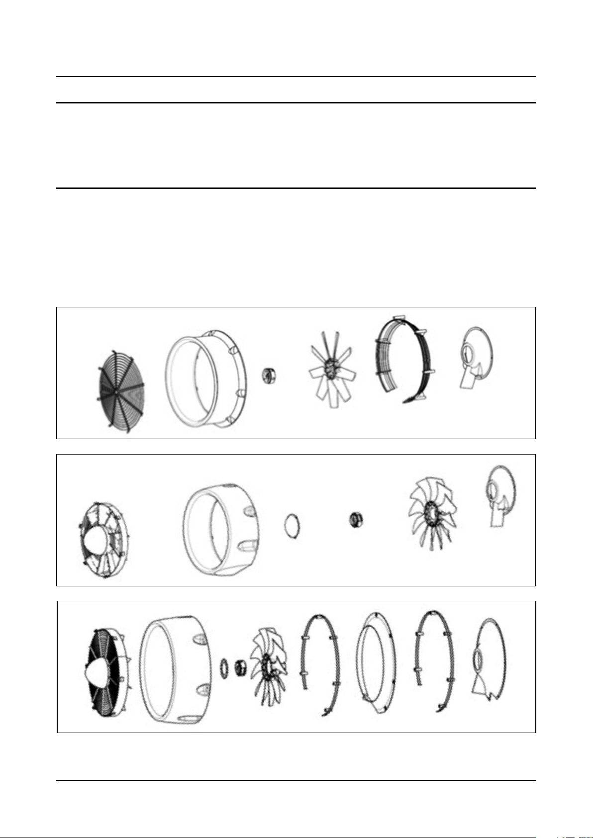
EF820, EF920, AB750, AB820, AB920, AG820 and AG920
The air kits are fitted with a grid with air guides at the air intake, which forms the air flow before reaching the fan, to
decrease the imbalance in the airflow. The fan is either 820 or 920 mm of diameter and is fitted with blades made of a
hardened synthetic material. This reduces the power consumption to a minimum as a result of low material density.
There is a channel between the air intake and the cone of the air kit which increases the air speed through the outlet,
and ensures that a high uniformity in air distribution is achieved.
EF
AB
AG
19
Page 24

3 - Description
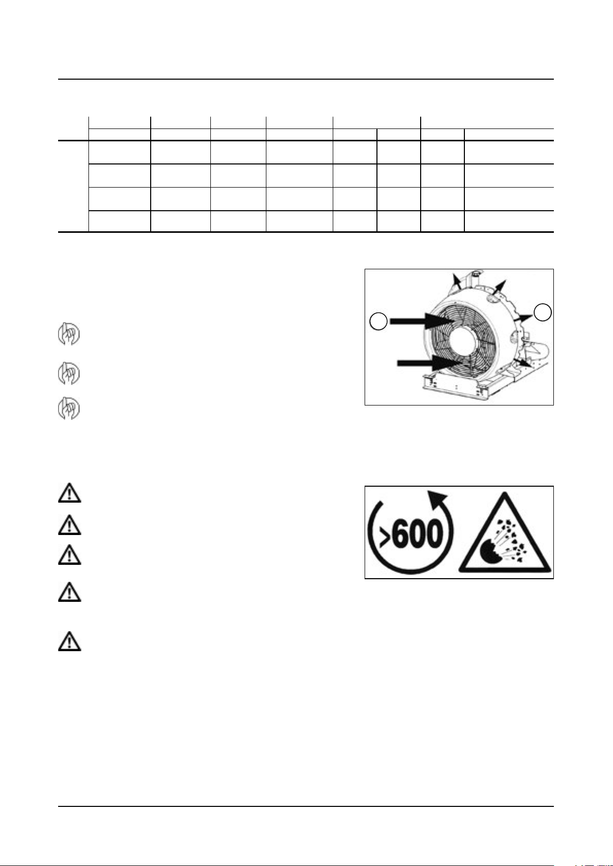
NEVER exceed 540 r.p.m. on the tractor P.T.O.! The fan may explode if overspeeded!
KEEP AWAY from the air inlets and outlets while the fan is on. Some objects may be shot out of the air outlet or a
piece of clothing could be sucked into the air inlet.
The fan is the most dangerous part of the machine. Do not try to replace any of the parts without consulting your
HARDI dealer first. Any service job or modifications on fan and air kit is to be carried out by your HARDI dealers
qualified technicians.
20
Page 25
Aif flow for axial air kits
Blower unit Speed Relationship Fan diameter Power Air flow
AB820
AB920
ZENIT
AG820
AG920
1st low
2nd high
1st low
2nd high
1st low
2nd high
1st low
2nd high
1:3.5
1:4.4
1:3.5
1:4.4
1:3.5
1:4.4
1:3.5
1:4.4
820 mm / 32”
920 mm / 36”
820 mm / 32”
920 mm / 36”
Protective grid
The air kits are fitted with protection grids. They are fundamental for
avoiding accidents and for stopping foreign bodies from getting inside
the air kit.
Tractor drivers seat is the intended working place during
operation.
3 - Description
kW Hp m3/h cubic foot/minute
25
32
27
33
27
33
30
36
35
44
38
45
38
45
42
50
36.000
43.000
42.000
50.000
43.000
50.000
51.000
60.000
21.000
25.000
25.000
29.000
25.000
29.000
30.000
35.000
A
B
This product is designed and should be used in orchard
products application.
Do never pass 540 rpm on tractor PTO.
Invers air inhalation
A is air inhale and B is air out let
DANGER! It is strictly forbidden to use the blower unit without
the protective grid.
DANGER! Do not approach the fan when in use.
DANGER! Do not introduce foreign bodies through the grid,
regardless of whether the fan is in use or not.
DANGER! During the working day, protect your hearing from
the noise produced with EN 352-1:1992 approved hearing
protection or similar.
DANGER! If you notice vibrations or unusual noise, stop the fan
immediately and consult your HARDI dealer.
21
Page 26
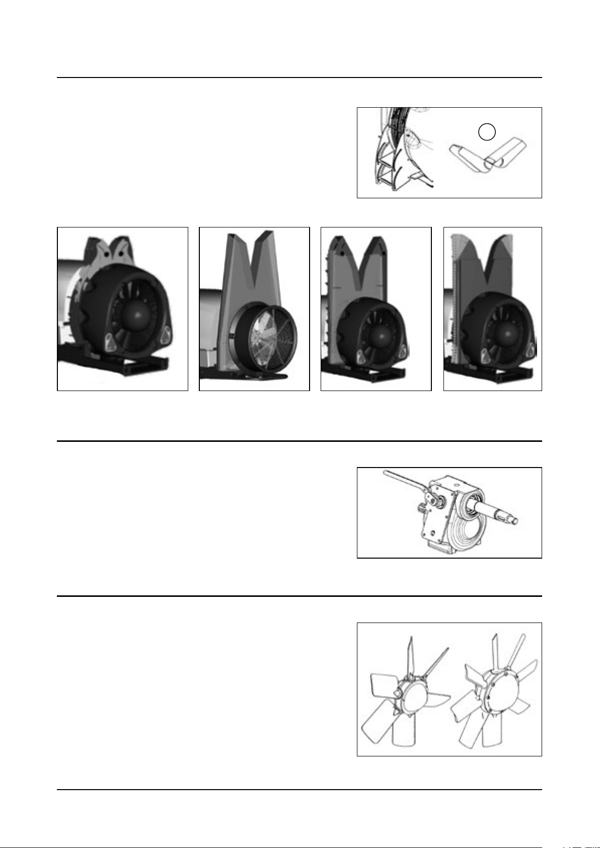
3 - Description
Deflectors
Axial air sprayer as well known as air sprayers can optionally be
equipped with mentioned deflectors.
Deflectors contribute to an increased efficacy in the spray job, as they
reduce drift, and provide direction of air and spray mist to the target,
according to adjustment.
V
Top DUO P DUO T JET
Gearbox
The AG820 and AG920 are fitted with a 2-speed gear box with a neutral
position. The front and lower area of the gear box are attached to the
chassis. It is fitted with a speed selector that prevent from jumping out
of gear when engaged.
The speed ratios are following:
1st speed, low gear: 1 – 3.6
2nd speed, high gear: 1 – 4.4
Fan
The axial fan has syntetic,impact proof blades resistant to high and low
temperatures as well as chemical products.
The blades have 3 different angle settings to adjust the air flow.To
change the angle see the section ‘ adjusting the fan’
22
Page 27
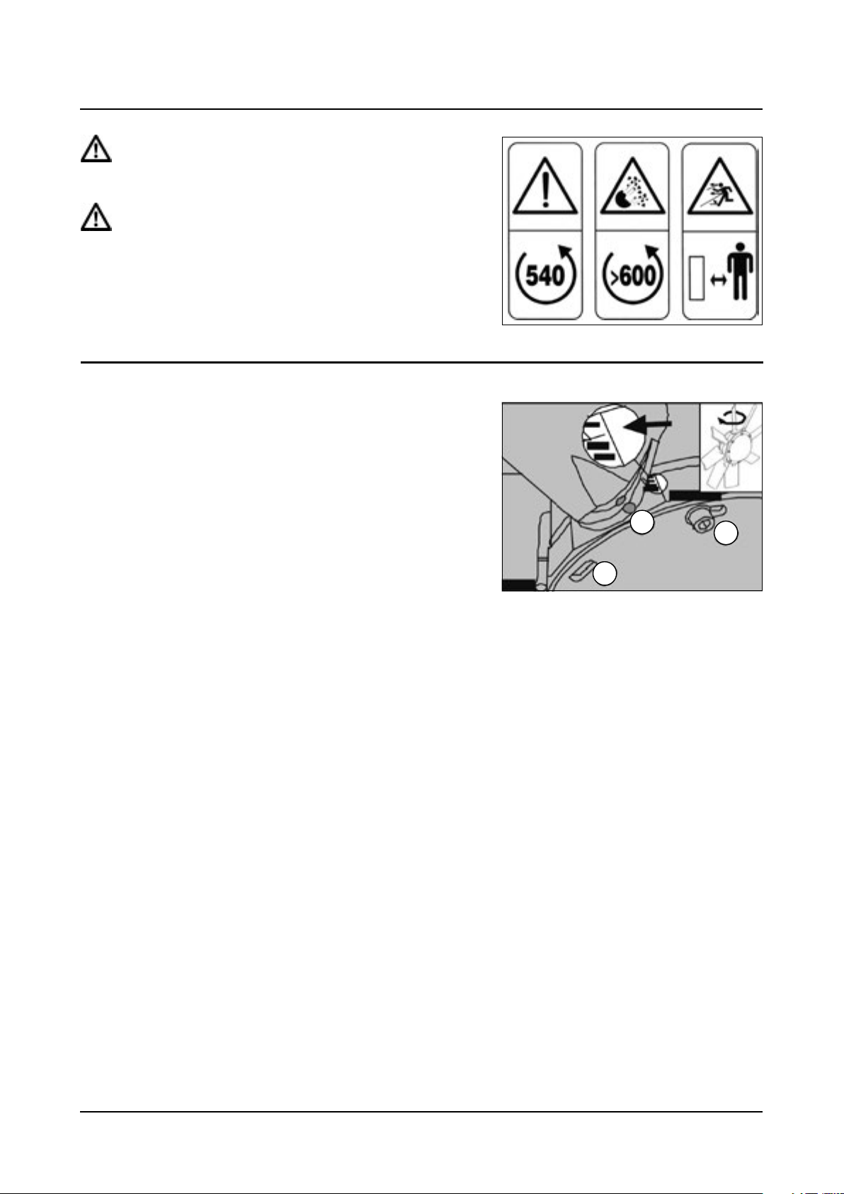
DANGER! NEVER exceed 540 rpmat the tractor PTO. Exceeding
540 rpm may cause severe damages to the fan and lead to
severe personal injury or death!.
DANGER! Keep away from the air inlets and outlets while the
fan is operating. Foreign objects may be expelled from the air
outlet or a piece of cloth could be sucked into the air inlet. Risk
of severe personal injury or death!.
The air kits are the most dangerous part of the machine. Do not repair,
change or modify any of the parts but leave this to your HARDI dealer.
Any repair jobs on air kits in requires qualified technicians.
Adjusting the fan
The angle of the fan blades can be adjusted to 4 positions. The factory
setting is normally pos. 3.
Decreasing the blade angle (minimum angle, position 1) reduces the
flow and power consumption. Increasing the angle (maximum angle,
position 4) increases the air flow and power consumption. This will
adapt the mistblower different applications tractor sizes.
To change the blade position you should do as follows:
1. Take off the suction grid.
2. Loosen the Allen screws (A) without taking them out
completely.
3 - Description
C
B
A
3. Loosen the Allen screws (B) holding the nut at the back of the
fan.
4. With both hands on opposite blades, turn them to the required
position between 1 and 4. All the blades should turn at the
same time.
5. Finally, check all the blades are in the same position (C).
23
Page 28
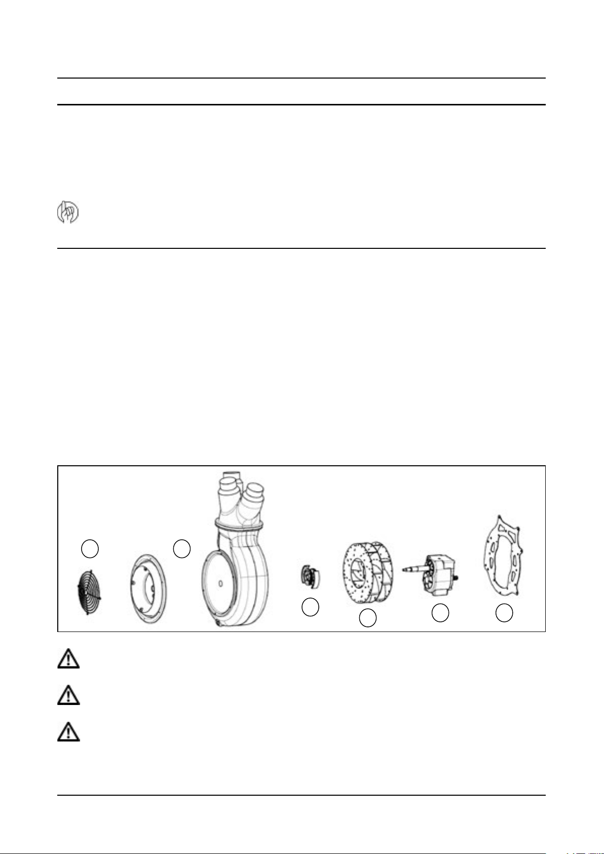
3 - Description
Centrifugal Blower Units
General information
The blower unit is located at the back of the machine. It contains a gearbox unit, blanking plate, crankcase, outlet hoses
and nozzles, turbine and clutch.
There are two different turbine models: the steel model assembled in P540 and P540D centrifugal blower units, and the
aluminium model assembled in HF600 blower units.
ATTENTION! The clutch is one of the most important parts in the blower unit in terms of safety. Make sure that it is
in perfect conditions (i.e. that it is not blocked, etc.). Otherwise, it could cause the blower unit to explode.
HF540 (TS3 P540 / TS6 P540 Single)
HF540D (TD3-P540 Double)
HF640D (TD3-P640 Double)
The air kit should adapt to the requirements of the booms width and crop in order to give the best application results.
The following section gives more details about the different pneumatic air kits available.
The letters HF***D means High Flow and Double, respectively. They have a polyethylene crankcase.
Crankcase and turbines with 540 mm / 21” or 640 mm / 25 “diameter.
Components
A. Grid
B. Polyethylene crankcase
C. Clutch
D. Steel turbine
E. Gearbox
F. Chassis
A B
C
D
DANGER! UNDER NO CIRCUMSTANCES should you exceed 540 r.p.m. from the tractor PTO as there is a serious
danger of air kit explosion.
E F
DANGER! STAY CLEAR of the air inlet and outlet while the turbine is in use. Foreign objects could be expelled from
the air outlet or parts of clothing could be sucked into the air inlet.
WARNING! The blower units are the most dangerous part of the machine. Do not attempt to alter any of its
components without checking with your nearest distributor first. Manipulating blower units to change their
characteristics should only be carried out by qualified personnel that has been expressly authorised by ILEMOHARDI S.A.U.
24
Page 29
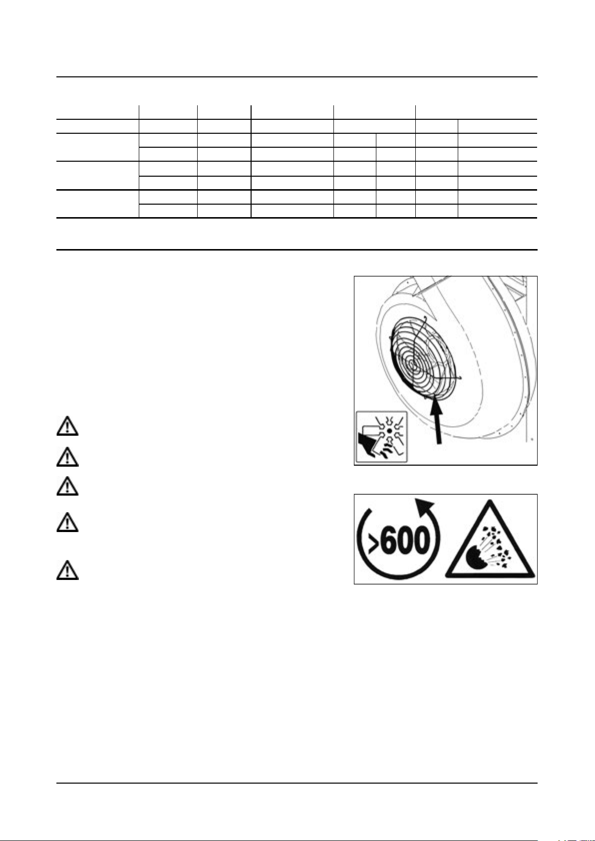
3 - Description
Air flow of HF540, HF540D and HF640D centrifugal turbines
Blower unit Speed Relationship Turbine diameter Power Air flow
m3/h cubic foot/minute
HF540 1st low 1 - 6.6 540 mm 12 Kw 16 HP 8.000 4700
TS3 P540 / TS6 P540 2nd high 1 - 7.8 16 Kw 21 10.000 5900
HF540D 1st low 1 - 5.7 540 mm 14 Kw 19 11.000 6500
TD3-P540 2nd high 1 - 6.6 22 Kw 29 15.000 9000
HF640D 1st low 1 - 4.5 640 mm 24 Kw 33 27000 16000
TD3-P640 2nd high 1 - 5.7 36 Kw 49 37000 22000
Protective grid
The blower units have protective grids fitted to the air inlets. They are
essential for avoiding accidents and preventing small stones, leaves or
other foreign bodies from entering the blower unit that could cause
damage inside the grid.
DANGER! It is strictly forbidden to use the blower unit without
the protective grid.
DANGER! Do not approach the fan when in use.
DANGER! Do not introduce foreign bodies through the grid,
regardless of whether the turbine is in use or not.
DANGER! During the working day, protect your hearing from
the noise produced with EN 352-1:1992 approved earmuffs or
similar.
DANGER! In the case of vibrations or knocking, stop the turbine
immediately.
25
Page 30
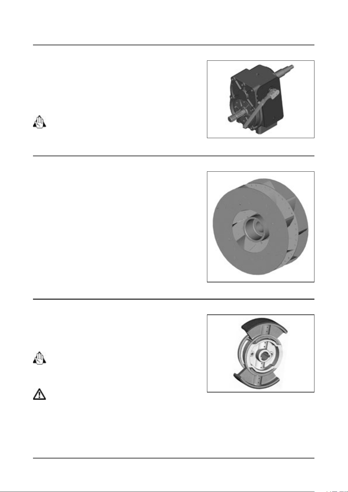
3 - Description
Gearbox
The HF540, HF540D and HF640D blowers have a two-speed gearbox
with neutral position.
Upper pos: High speed
Middle pos.: Neutral
Lower pos.: Low speed
DANGER! Do not attempt to engage or disengage the speed
with the PTO in operation.
HF540, HF540D and HF 640D Turbine
The HF540 and HF540D centrifugal blower units contain a galvanised
steel turbine. The difference between the single model and the double
model is that the double provides the same power as two single
turbines combined.
The position of the blades in this type of turbine is fixed. Their angle
cannot be changed like in axial fans.
The turbines are allowed to turn at a maximum of 540 r.p.m.
The clutch is in the centre of the turbine, which ensures smooth startup and stop. See section “Clutch” for further information.
Clutch (All blower types)
The clutch is integrated at the centre of all the fan models and will
ensure a smooth start-up and stop of the fan. The clutch design may
vary from model to model, but the functioning and maintenance is the
same.
WARNING! The clutch is a vital part in the blower unit. Poor
condition could cause the blower unit to break or explode.
The condition of this part should be regularly checked. Please
carefully read the section ‘Maintenance’.
DANGER! The clutch is one of the most important parts in the
blower unit in terms of safety. Make sure that it is in perfect
conditions (i.e. that it is not blocked, etc.) Otherwise, it could
cause the blower unit to explode.
26
Page 31

3 - Description
Light kit
The light kit can be fitted to the rear bumper at the fan. They are
connected via a universal plug adaptable to any make and model of
tractor.
Lights must be used when driving on public roads both inside
and outside urban areas. If any of the components would break,
they should be replaced immediately. In order for the device to
work, connect the plug to the light socket on the tractor.
Booms
Hardi offers 4 booms programs , LINER , ATLAS , BOXER or CRONOS.
The booms are equipped with pneumatic or hydro pneumatic spouts or IRIS drop legs.
If hydraulic folding and adjustment is offered , it is direct to the tractor or electro hydraulic , see separate chapter.
The LINER boom
Manual adjusted support to position spray device either behind the turbine with the FIX system, or on each side of the
turbine unit, the START system. Both can be combined to START FIX boom system.
Optimally, last mentioned can be offered with hydraulic side adjustment.
An in-between row solution.
LINER FIX LINER START H0 LINER START H2 LINER START FIX H0 LINER START FIX H2
27
Page 32

3 - Description
The ATLAS boom
The boom program is divided in following versions , START, AGILE and SOLID.
According to specification, hydraulic adjusted , The SOLID addition is as well offered in a GV version, Geometry Variable.
ATLAS START ATLAS START H2 ATLAS START H3
28
ATLAS AGILE ATLAS SOLID CONVERT
ATLAS SOLID GV FIX ATLAS SOLID GV FIX CONVERT
Page 33

3 - Description
The BOXER boom
3 additions , START, AGILE and SOLID
Hydraulically adjusted the first have a light structure and SOLID is reinforced and wider boom structure.
BOXER START HORIZONTAL H2 BOXER START HORIZONTAL H3 BOXER START HORIZONTAL H5
BOXER AGILE HORIZONTAL H2 BOXER AGILE HORIZONTAL H3 BOXER AGILE VERTICAL H5
BOXER SOLID HORIZONTAL FIX
BOXER SOLID HORIZONTAL CONVERT
BOXER SOLID VERTICAL FIX
BOXER SOLID VERTICAL CONVERT
29
Page 34

3 - Description
The CRONOS boom
The boom program is divided in the following versions , SOLID, RIDER and VARIA
According to specification, hydraulic adjusted. Common for all booms is the rubber bump absorber in the boom wing.
SOLID has no trapeze suspension. RIDER & VARIA has trapeze suspension.
All 3 versions of the CRONOS boom are offered in FIX boom wing ( no angling – Tilt function in boom wing, or GV boom
wing ( Geometry Variable ) allows Tilt up in positive 60º and negative -25º down to adapt to the target.
The inner spray device can optionally be hydraulic adjusted but the “ADAPTA” as well as the outer device can optionally
be hydraulic adjusted
CRONOS SOLID CRONOS SOLID GV
CRONOS RIDER CRONOS RIDER GV
30
CRONOS VARIA CRONOS VARIA GV
Page 35

Variant boom
The boom is offered from 7 to 13 m, hydraulically folded , fitted with
pneumatic or hydra pneumatic spray spout. Boom up to 7 m are cross
folded, larger boom are bi articulated, and folds parallel with sprayer
tank.
3 - Description
31
Page 36

3 - Description
Break away clutch
All boom wings are equipped with brake away clutches, in vertical as well as horizontal direction, according to boom
specifications
The clutch is adjusted according to boom weight and field conditions.
Soft and loose the clutch. Loosen counter nut A, loosen bolt B. To tighten clutch to be harder; loosen nut A, tighten bolt
B. Tightness must never be harder than 15 Kg / 30 pounds, or the outer boom wing will open / activate the boom clutch.
B
A
Particulairly for CRONOS boom
The boom’s wirn is equipped with a non-adjustable rubber sustention
B, to absorb the knocks from driving in the field. Be sure that the
rubber parts are intact, and bolts are in place with the part well
threaded over the bolt.
B
A
B
32
Page 37

Pneumatic spray system
3 - Description
The pneumatic system is low pressure. This system takes advantage of
the high air speed in the spout outlet to break the spray liquid and give
a very fine mist together with turbulence. Using the deflectors at the
spout outlet, the mist means that the liquid is distributed uniformly.
There are four spout models, which can be combined according to the
bar type and assembly requested for the machine:
A. Cannon with 1 atomizer
B. Spout with 2 atomizers
C. Spout with 3 atomizers
D. Spout with 4 atomizers
The Paraflow pneumatic system is low pressure. This system takes advantage of the high air speed at the pipe outlet to
break the spray liquid and give a very fine mist together with turbulence. Using the deflectors at the tube outlet means
that the liquid is distributed uniformly.
There are two Paraflow models, which cannot be used together,
according to the bar type and assembly requested for the machinery:
Paraflow tube with 4 in-line atomizers
Paraflow tube with 6 in-line atomizers
ATTENTION! Ceramic nozzles are used for the standard
pneumatic system and the paraflow system. This type of nozzle
has two positions. If the nozzle is fitted so that the flow enters
on the flat side, less flow will be allowed than on the conical
side
A
C
D
B
Hydropneumatic spray system
The hydropneumatic system is medium-high pressure. This system
takes advantage of higher turbulence in the low-volume conical nozzle
and sprays the liquid with an even distribution. The air reaches high
speed in the spout, spraying the liquid in a fan.
There are three spout models with three or five nozzles. These two
models cannot be combined.
E. Spout with 3 nozzles.
F. Spout with 5 nozzles.
Where not all the nozzles are required in treating the crop, the nozzles
can be replaced for caps.
E
F
33
Page 38

3 - Description
IRIS system, continuation of Hydro pneumatic system
The IRIS application system allows individual air adjustment as each
outlet permits steep angling or even closing of the air supply, if
necessary. The IRIS system provides the required droplet size and air
conduction to the target. The most delicate and difficult part of the
vine, the grape cluster, is safely treated throughout the season, due to a
very easy and quick calibration with the IRIS system.
A. Non-drip valve
B. Nozzle
A
B
C
C. Vane position indicator (angle)
D. Air vane adjustment
E. Air vanes
D
E
34
Page 39

General information
Unloading the mistblower from the truck
When loading or unloading the mistblower to/from a lorry by using a
lever and pulley or a crane, use the suspension points shown on the
diagram and make sure the straps used are strong enough.
DANGER! Nobody must stand below or next to the machine
during loading or unloading.
4 - Starting up
Before starting up for the first time
Although the surface of the metallic parts of the mist blower have been coated with a strong, protective product, we
recommend you to apply a layer of anti-corrosion oil (e.g. CASTROL RUSTILLO or SHELL ENSIS FLUID) to all metal parts to
avoid chemical products from discolouring the enamel, as well as to ease future cleaning.
ATTENTION! This treatment should be carried out whenever the protective layer wears off.
Counterweights
Check if it is necessary to place a counterweight on the front of the
tractor, to increase the stability and steering performance.
35
Page 40

4 - Starting up
Coupling the driveshaft
Initial installation of the driveshaft may involve having to cut the axle to
adapt it to the tractor to which it will be hitched. To hitch it for the first
time, proceed as follows:
1. Attach the mistblower to the tractor in such a way that the
distance between the PTO shaft and the mistblower pump is
the shortest possible.
2. Stop the engine and remove the ignition key.
3. If the driveshaft needs to be shortened, pull the two parts of the
shaft apart. Fit the two parts of the shaft, one to the tractor and
the other to the mistblower crankshaft and measure out the
length that needs to be removed. Mark the protection guards.
ATTENTION! The shafts must always have a minimum overlap of
one third of their working length.
4. Cut both parts equally, using a saw. File the profiles afterwards
to remove burrs.
5. Grease the profiles and reassemble male fitting and female
fitting.
6. Fit the shaft to the tractor PTO and to the mistblower pump
shaft.
min. 20 mm
1/3 1/3 1/3
min. 150 mm
min. 20 mm
7. Place the input part towards the tractor. Fit the chains to
prevent the protection guards from rotating with the shaft.
ATTENTION! To ensure long life of the driveshaft and prevent
possible damage to the equipment, try to avoid working at
angles of more than 15°.
36
15º max
Page 41

Hooking up the mistblower
If your mistblower has a semi-automatic quick hitch, follow the steps
set out below:
1. Place the quick hitch boom in the hydraulic lift arms of the
tractor.
2. Fit the linch pins to secure the boom to the hydraulic lift arms.
3. Completely lower the boom with the tractor’s hydraulic lever.
4. Reverse the tractor until it touches the chassis, placing this as
near the middle as possible.
5. Attach the top link to tractor and sprayerand adjust it by hand.
6. Raise the tractor’s lower links with the hydraulic lever until the
boom fits perfectly into place.
7. When the boom is correctly attached, the two hooks will close
automatically and the equipment will be fixed to the tractor.
8. Put the safety pins of the semi-automatic quick hitch on
to avoid the equipment from becoming detached during
transportation or spraying.
4 - Starting up
9. Place the equipment at the height needed.
10. Ajdust the top link until the equipment is completely
perpendicular to the ground.
To detach the mistblower you should proceed in the following way:
1. Lower the tractor’s hydraulic arms with the hydraulic lever until
the equipment is touching the ground.
2. Pull the cable release the boom from the semi-automatic quick
hitch.
3. Loosen the top link
4. Pull out the retaining pin from the top link to completely detach
the mistblower.
5. Drive the tractor away slowly.
WARNING! The tractor’s hydraulic lower links should be moved
very gently to prevent damages or tipping over.
37
Page 42

4 - Starting up
Hydraulic connections
General information
Make sure that the couplings are clean before fitting them!
After pressing the brake pedal and when the system has filled with oil, check the level of hydraulic oil in the tractor and
refill if required.
DANGER! Testing the hydraulic system should be done with care. Air may have entered the system and cause
sudden movements.
DANGER! Oil leakage: Do not use your hands under any circumstances to locate a leakage in any point in the
hydraulic system. Due to the system’s high pressure, the oil could penetrate the skin.
Tractor requirements
Hydraulic pressure of 180 Bat and a flow of 20 l/Min or 5 gal / min.
Below you’ll find a table where the boom requirements are listed as 2D = 2 double acting hydraulic outlets 3D = double
acting outlets etc.
Converted to 1 Double acting outlet.
All booms offer optionally a Small Joystick S3 or S5 to cover up to 5 double acting functions into just 1 double acting
outlet.
Larger booms and sprayer with Combus circuit, are offered with V hydraulics, known as well as DAH – Direct activated
Hydraulic.
Boom Hydraulic rams
Liner
Fix N
Start N
Start Fix N
Atlas
Start H0 N
Start H2 2D S3 or controlbox
Start H3 3D S3 or controlbox
Agile Fix H3 3D S3 or controlbox
Solid FIX H3 3D S3 or controlbox
Solid Convert H3 3D S3 or controlbox
Solid GV Fix H5 5D S5 or controlbox
Solid GV Convert H5 5D S5 or controlbox
Boxer
Start 2D or 3D or 5D S3 or S5 or controlbox
Agile 2D or 3D or 5D S3 or S5 or controlbox
Solid 3D or 5D S3 or S5 or controlbox
Cronos
Solid H3 3D S3 or combus
Solid GV H5 5D S5 or combus
Rider H3 3D S3 or combus
Rider HV H5 5D S5 or combus
Varia Convert H5 5D S5 or combus
Varia GV Convert H7 7D Combus
Operated by
Optional or default
38
Page 43

Electrical connections
General information
If your equipment includes an electrical component, please note the
following information to correctly connect the equipment and to
prevent problems when working.
The voltage required by the electrical components is 12 V. Before
connecting any component, make sure that the polarity is correct.
Red wire = 12 V (+ positive)
Black wire = (- negative)
The connectors assembled on the electric components comply with
the standards for the majority of modern tractors. If your tractor has
another type of power supply connector, the supplied connector will
need to be removed and adapted to the tractor connector.
Electrical operating units
Find a place in the tractor’s cab where it is possible to fit the control
box so you can operate it as comfortable as possible. The most
recommended place is to the right of the driver’s seat.
12 V
-
Blue
4 - Starting up
+
Brown
The control box must be properly attached to prevent it from being hit
or from excessive vibrations.
The connector type is universal and it should be able to be connected
to any tractor. Do not hock into coincidently wires in tractor cabin, as it
will not secure stable power and current.
Minimum requirement: min 11V max 13 V
Amp. Per SV section 2.5
Amp. Per CB section 0.75
As an emergency solution, remove the connector and splice the wires
directly to the battery, remember to have fuse in-between.
The control box must be properly attached to prevent it from
being hit or excessive vibrations.
The connector type is universal and it should be able to be connected
to any tractor.
As an emergency solution, remove the connector and splice the wires
directly to the battery.
WARNING! Always remember: Red wire (+) Black wire (-)
A
12 V
B
Connection
to sprayer
DANGER! Always turn off any spray computer before you
unplug the power supply and cable to the sprayer.
Data transmission must stop, before power supply is stopped.
39
Page 44

4 - Starting up
Rate controller
Rate controller DB 3610
Display
DB 3610
Fluid Box
FB 3610
Power BOX
Hydraulic box
HB 3610
out put out put
The Job boxes for input and out put signals
40
Page 45

Rate controller DB 3620
Display
DB 3620
Fluid Box
FB 3620
4 - Starting up
Hydraulic box
HB 3620
Power BOX
out put out put
The Job boxes for input and out put signals
41
Page 46

4 - Starting up
Fluid circuit
Suction filter
The mesh size of the standard filter is 50 mesh. 80 and 100 mesh filters
are available and can be changed by opening the top lid of the filter.
Check the O-ring before replacing the lid and replace it if it is damaged.
ATTENTION! For better sealing between the lid and the O-ring,
coat the area between the joint and the lid with grease. This will
make the O-rings seal and avoid suction of false air.
Pressure damper
The air pressure of the pulsation damper (321 pump) is factory-set at 2
bar to match spraying pressures between 3 and15 bar.
When spraying with different pressures than this, you must change
the pressure of the damper. Follow the list to adjust it to the correct
pressure. This table is also engraved on the damper.
Spraying pressure Pulsation damper air pressure
bar bar
1.5 - 3 0 - 1
3 - 15 1 - 3
15 - 25 3 - 4
Diaphragm pump
Before starting to use the machine, make sure the diaphragm pump is
well greased to prevent wear.
The pump is greased from factory, but should be greased again during
bedding in and then every 50 hours.
42
Page 47

4 - Starting up
Deflectors
ATTENTION! Never access area or adjust deflector or any other part near the air kit, while tractor is started.
V deflector
Park the sprayer in the orchard, between 2 tree rows, adjusted is
visually to point towards the tree top.
Tight up adjustment bolts, test with clean water. And verify target is
well sprayer.
Top S or L
S the short version L the slightly higher version.
Parked between rows, orientate the adjustable air outlet towards the target, and test with clean water.
Top S adjust from 90º to 50º
Top L adjust from 110º to 70º
Adjustable bottom deflector
Allows to drive the upwards, and avoid air turbulence on the ground
and stem, as often used in e.g. plum orchards
Adjust it between rows, test with clean water.
43
Page 48

4 - Starting up
DUO P deflector
Fixed position of air outlet, nozzle holders placed in front of the air
outlet, easy accessed for calibration.
DUO T and V deflector
Provide adjustability in the top of the deflector, to secure direction of
air and spray mist towards the target. Loos the hand wheel, position
the adjustable part in visual direction to the target, tighten up the
hand wheel and test with clean water.
JET deflector
Provide adjustability in the top of the deflector as well in the lower
part.
Loosen the bolts of the adjustable bottom and top part, adjust it
visually towards the target, tighten the bolts and test with clean water.
44
Page 49

4 - Starting up
Booms
General information
All the booms have either minor or major options to adapt to the crop, all according to the technical level of the boom
structure.
FIX
The FIX boom, provides height and width adjustment of spraying
device by loosening the bolts X and Y, positioning the spray device and
tightening again.
Width adjustment from 7” to 40”.
START
Provides telescopic width adjusted by loosening the bolt in pos, X.
Once positioned, tighten the bolts again.
Width adjustment from 1.1 m to 1.8 m or 40” to 72”
The extreme part of the START boom can be equipped with 60º
angling bracket, depends of chosen spout set up. Remove pin bolt in
pos. X and poisoning according to the crop.
The bracket as well allows to be turned 180º down wards by loosening
bolts A
45
Page 50

4 - Starting up
ATLAS START
Provides adjustment of outer spray devices from 10ft to 13ft as well as in center section, left and right plus minus 8” or 20 cm.
In Metric: booms adjust from 3.1 m to 3.9 m in section A on the drawing, and central parts section B, adjust 0.2 m in both sides.
Loosen up fixation bolt in mentioned A and B area adjust and tighten again.
ATLAS AGILE
Boom wing width as ATLAS START, but combines with the FIX boom bracket
ATLAS SOLID FIX and ATLAS SOLID FIX GV
The boom wing width adjust from 13,7 ft. to 18ft or 4,2 m to 5,5 m
The centre section is the FIX system, consult description above.
ATLAS SOLID CONVERT and ATLAS SOLID GV CONVERT
Same boom width as above, ATLAS SOLID, for adjustment of CONVERT boom part. Consult description above.
46
Page 51

BOXER START
Boom wing telescoping hydraulic adjustment from 8.5ft to 12.7ft
Or 2,6 m to 3,9 m
Adjustmet of center section , see relemavnt description under ATLAS
START.
BOXER SOLID VERTICAL FIX or CONVERT
Telescopes from 11.8ft to 15.7ft or 3,6m to 4,8m
Rear part FIX or CONVERT side adjustment, consults the respectively
description above.
4 - Starting up
BOXER SOLID HORIZONTAL
Telescoping boom from 1,8 m to 5,4 m or 5.9ft. to 17.7ft.
Rear part FIX or CONVERT side adjustment, consults the respectively
description above.
47
Page 52

4 - Starting up
Adjustment of BOXER boom
Important to avoid destructive slack in the telescoping part, the slack
must be adjusted.
Loosen counter but A tighten in bolt B , not the press into the
telescoping boom part, but just hold it firm and avoid slack. Tighten
counter nut again.
Grease the part every 200 hours or annually.
The indicated nylon friction parts must be kept clean, avoid sand and
dust in them.
Replace when worn.
CRONOS BOOM
Exist as SOLID , RIDER , GV or VARIA
SOLID
A
B
7.1 me boom width, the spray device can easily be positioned on the
boom with and or in the centre section.
The booms wing is equiped with a non adjustebale rubber suspention,
to absorbed the knocks from driving in the fied. Secure the rubber
parts is intacts , and bolts are in place with luck part threaded well in
over the bolt.
48
B
Page 53

RIDER
Has additionally to the boom wing rubber suspension, as well trapeze
suspemtion in the centre section.
Keep moveable part free from dust and dirt, grease weekly / every 50
hours.
VARIA
The CRONOS VARIA provides hydraulic side adjustment, from the driver
position.
4 - Starting up
The central part A is telescoping 0.65 m ( 26”) to left and to the right
side.
Secure the telescoping part is well lubricated, and all ways kept clean
from sand and dust. The telescoping part is guide in nylon friction
pads, secure they are in proper.
Once the VARIA system is telescoped out, it is not permitted to fold the
boom, all ways recall the VARIA system and then fold.
The drawing illustrates the VARIA system telescoped out to max
position.
A
A
CRONOS GV
As the RIDER and individual boom wing tilt.
Outer boom element can as well be positioned sideward, optionally
with hydraulic piston.
49
Page 54

4 - Starting up
General for all boom models
Break away clutch
All boom wings are equipped with brake away clutches, in vertical as well as horizontal direction, according to boom
specifications
The clutch is adjusted acording to boom weight and field conditions.
Soft and loose clustch. Loosen counter nut A , loosen bolt B. To tighten clutch to be harder; loosen nut A , tighten bolt B.
Tightnes must never be harder than pusc of 15 Kg / 30 pounds, on the outer boom wing will open / activated the boom
clutch.
B
A
Adjustment of hydraulic fold
To achive the correct folding position of the boom wing, the folding
cylinder must be adjusted.
B
A
Undoo the counter nut A, remove the cylinder eye B from the position,
turn it either futer in or out acodingly to find the right possition of the
boom in transport as well as in working / spraying position
50
B
A
Page 55

Transport bracket
The tranport bracket mist secure the boom wing in transport. To
position it, loos the indicated bolts, and adjuste to firm resting position
of the boom, and tighten bolts again.
Inspect weekly the tranposrt bracket , and secure the nylon friction
pars are inatct.
Adjustment of upright
The upright needs to be adjusted for slack between the male and feel
tubes.
Tighten on the two indicated nuts, just to make it press gently on the
inner male tune, if too tight it will not be moveable, too loos it will have
destructive slack.
4 - Starting up
A nylon friction part is pressed towards the inner male tube; keep it
clean from dust and sand. Replace the nylon friction part when worn.
Adjustment of out spray device
The out spray device is easily adjusted
The manual version is by losing the indicated bolt A, move it to desired
position, and tighten again the bolt.
A
51
Page 56

4 - Starting up
The hydraulic version
Make sure the indicated bolt B is not pressing hard on the sliding part,
the black nylon roller must run freely in the rail.
According to the spray device, the outer positioning is as well as in the
picture. To adjusted to desired poisoning, loosen the indicated bolt, A,
move the spray device to correct position, tighten bolt again.
B
A
Adjustment of inner 4 spray device
The optional S bracket, as indicated by the arrow in the photo, can be
mirrored 180º Thereby the spray device is able to be positioned behind
the sprayer.
Undo the 2X 4 bolts, turn the bracket 180º and fit all bolts again.
The Convert brackets provides a telescoping side adjustment, loosen
the indicated bolts, slide the inner boom tube to desired position, and
tighten again the bolts, just enough to let the nylon friction pads press
and hold it in position.
52
Page 57

Hydraulic adjustment of the Convert brackets
Optionally the boom ca has the side adjustment hydraulically, done
from the tractor cabin.
In that case let the above indicated friction pads are just as loos as it
allow the inner tube to slide in and out easily.
IRIS system setup
The IRIS application system is standard equipped with ceramic hollow
cone nozzles. Each drop leg holds 8 nozzles per drop leg. If a curtain
area of the canopy is not meant to be sprayed, a small valve is fitted as
per two nozzles that allow turning of the spray mist. If only one nozzle
is needed in that area it is as well possible to fit a blind cap.
4 - Starting up
A
In the valve A that allows the spray mist to pass on the nozzle, there
is a small no drip valve, that secures when the main switch turns of
the spray mist, that all nozzles stops instantly, and do not spill on the
ground.
The nozzles B are fitted in an adjustable support, in order to angle
them forward accordingly to forward speed, and there by not loosing
spray mist behind the sprayer.
The air outlet has an indicator C that shows the angling of the air
wanes E which are adjusted by pressing bottom D in, and then move
up or down the vanes E.
The air outlet in the lower part shall be orientated upwards to get the
spray mist penetrating from down and upwards. The upper spout shall
point downward in order to avoid drift. Those setting are accordingly
to grot hog the canopy, and adjustment is necessary during the
season, as the size of the canopy change.
In order to get the optimal cross flow effect and penetrate the canopy
the IRIS drop leg shall be set 10º , 15º , 20º or 30º forward, as indicated
in the adjustable part in the top of the drop leg. The forward angling is
set accordingly to forward speed while spraying.
B
D
C
E
53
Page 58

4 - Starting up
Cannons
On CANNON models, there are three different spout types. Model L is
only fitted on variants with one turbine. It comprises 4 bi-jet holders
with two nozzles each. In addition to the spout nozzles there are three
adjustable nozzles outside the spout which allows to treat the nearby
crops also.
Model T is itted on variants with two turbines. It has 7 bi-jet holders
in a star-shaped pattern with three nozzles each. In addition to these
nozzles, there are three adjustable nozzles outside the spout which
allows to treat the nearby crops also.
Model M is fitted on variants with two turbines. It comprises an outlet
of 10 nozzles and there are two more with three nozzles each. You can
adjust the direction in which the ends of the upper and lower spouts
points.
Calibration
Enter to www.hardi-international.com and download the Excel
programme for calibration.
The working distance given in, is total sprayed distance. If two rows of
1,8 then multiply by 2 that equals 3,6 m.
Chech your speed.
See as well mistblower technique on www.hardi-international.com
54
Page 59

Blower unit
Safety information
The fan must not be in operation when driving on public roads. The
nozzle opening function should never be used on public roads. Any
failures could cause injury to persons and animals or damage to crops
In the event that the machine needs to be in operation (agitation)
while driving along public roads until reaching the field, make sure that
the gearbox speed selector is switched to neutral position.
DANGER! If any unusual noise or excessive vibration in the air kit
is detected then stop the equipment immediately and have it
serviced by an authorised HARDI technician.
Selecting the gear
The low or high gear can be selected using the specially designed
lever.
On the rear, left-hand side of the machine the selection lever is
accessed between the tank and fan.
To change the speed, pull the lever outwards (A) and then move it up
or down as required. Lock the lever in the selected position (at the lid)
Bottom position: 1st gear or low speed (1).
5 - Operation
2
A
0
B
1
Top position: 2nd gear or high speed (2).
Centre position: Neutral (0).
ATTENTION! Do never drive and fold booms at same time. Never
maneuverer the sprayer unless the boom is 100% unfolded,
otherwise the upright will be damaged. When the boom is
folded, it must rest on transport bracket before driving.
55
Page 60

5 - Operation
While moving the Sprayer
The booms must be 100% unfolded or resting in the transport bracket.
The boom must unfold, and stay firmly, stiff, not wobbly . If the boom is not held firmly unfolded during spraying, it will
auto destroy structure due to movements, caused from lack of firm position.
See maintenance and starting up (Adjustment of hydraulic fold).
Secure folding cylinder is correctly adjusted, and eventually stop positions / stop bolts, are adjusted correctly in order to
secure the boom stays stiff and firm while working. To underline, eventually trapeze or pendulum suspension, must be
activated, not looked , it most bee movable and floating.
56
Page 61

Adjusting the fan AB820
The angle of the fan blades can be adjusted to 4 positions. The factory
setting is pos. 3 (40º). Decreasing the angle of the blades (minimum
angle, pos. 1 (30º)), reduces the air flow and power consumption.
Increasing the angle (maximum angle, pos. 4 (45º)), will increase the air
flow and power consumption. It allows the mist blower to be adapted
to the different spray jobs and tractor sizes.
To change the angle of the fan blades you should follow these steps::
1. Loosen the Allen screws without taking them out completely.
2. Loosen the Allen screws whilst holding the nut at the back of
the fan.
3. With both hands on opposite blades, turn them to the desired
position between 1 and 4. All the blades should turn at the
same time.
4. Finally, check that all the blades are in the correct position.
5. Tighten all the screws.
IMPORTANT The fan must be calibrated correctly atter changing
pitch setting.
For technical details ask your dealer and factory.
5 - Operation
C
A
B
Single side blinds (Optional)
The air stream can be blocked to one side to prevent spraydrift towards
sensitive areas.
This is used when one section valve is shut during spraying along
orchard edges, streams, open waters or other sensitive areas where
spray drift must be kept away.
Loosen the nuts, slide the blind over the air outlet and tighten the nuts
again.
ATTENTION! Only blind one side at the time. Never close both
sides at the same time!
57
Page 62

5 - Operation
Liquid and air circuits
Filling/washing location requirements
When filling the sprayer with chemicals and water it is important to avoid spot contamination by spray chemicals in
order to protect the subsoil water resources.
A. If the mistblower is always filled at the same place, a special filling/washing location should be established. This
should have a hard, liquid-impenetrable surface (e.g. concrete) securing against seepage and edges securing
against run-off to the surrounding areas. The place should be drained to an adequate receptacle (e.g. slurry tank
or similar).
Any spillage or washings should be retained and diluted in order to be distributed on a larger area to ensure
minimal environmental impact and avoid build-up of larger chemical concentrations at one spot.
If no other requirements of distances exist, the following general recommendation of distance could be used. Not
closer than:
1) 50 metres from public water supplies for drinking purposes,
2) 25 metres from non-public water supplies for drinking purposes, treatment sumps and cesspools of drainage
systems, and
3) 50 metres from surface water (watercourses, lakes and coastal waters) and from nature reserves.
B. Alternatively the sprayer can be filled in the field where the spraying is to take place. If so, choose a different
location for each refilling.
If no other requirements of distances exist, the filling should not be established closer than:
1) 300 metres from public or non-public water supplies for drinking purposes and
2) 50 metres from surface water (watercourses, lakes and coastal waters), treatment sumps, cesspools of drainage
systems, and nature reserves.
ATTENTION! Legislation and requirements vary from country to country. Always follow local legislation in force at
any time.
NOTE! It is the responsibility of the sprayer owner/operator to comply with all relevant legislation. HARDI cannot
undertake any responsibilities for incorrect operation and use.
Suction Filter
This is located on the bottom left-hand side of the equipment and is
easy to access. To clean the filter you should do as follows:
1. Close the three-way valve.
2. Shut the valve of the filter (A) before dismantling the filter.
3. Undo the filter housing (B) to access the filter screen.
4. Clean the filter (C) and assemble in reverse order.
A
The filter should be cleaned after each spray job while remining spray
liquid is still agitated. This will prevent operational problems caused by
sediments.
58
C
B
Page 63

5 - Operation
Filling/washing location requirements
When filling the sprayer with chemicals and water it is important to avoid spot contamination by spray chemicals in
order to protect the subsoil water resources.
A. If the mistblower is always filled at the same place, a special filling/washing location should be established. This
should have a hard, liquid-impenetrable surface (e.g. concrete) securing against seepage and edges securing
against run-off to the surrounding areas. The place should be drained to an adequate receptacle (e.g. slurry tank
or similar).
Any spillage or washings should be retained and diluted in order to be distributed on a larger area to ensure
minimal environmental impact and avoid build-up of larger chemical concentrations at one spot.
If no other requirements of distances exist, the following general recommendation of distance could be used. Not
closer than:
1) 50 metres from public water supplies for drinking purposes,
2) 25 metres from non-public water supplies for drinking purposes, treatment sumps and cesspools of drainage
systems, and
3) 50 metres from surface water (watercourses, lakes and coastal waters) and from nature reserves.
B. Alternatively the sprayer can be filled in the field where the spraying is to take place. If so, choose a different
location for each refilling.
If no other requirements of distances exist, the filling should not be established closer than:
1) 300 metres from public or non-public water supplies for drinking purposes and
2) 50 metres from surface water (watercourses, lakes and coastal waters), treatment sumps, cesspools of drainage
systems, and nature reserves.
ATTENTION! Legislation and requirements vary from country to country. Always follow local legislation in force at
any time.
NOTE! It is the responsibility of the sprayer owner/operator to comply with all relevant legislation. HARDI cannot
undertake any responsibilities for incorrect operation and use.
Filling with water
The tank should be filled to a third of its capacity with clean water
before. adding the chemical product. Always follow the instructions
given on the product label!.
WARNING! If spray liquid is left in the tank, for safety reasons all
valves must be shut.
Draining the main tank
To empty the tank via the drainage valve, turn the pin on the lower
right- hand side of the auxiliary tank. To close it again, turn the pin
again and the valve will close automatically.
WARNING! Do not forget to use protective clothing and gloves
when doing this.
59
Page 64

5 - Operation
Pressure filters
Pressure filters will catch any remaining impurities and prevent nozzles
clogging. To avoid blockage of those filters it is very important to check
them regularly and clean them after each spray job to avoid chemical
residues to deposit and block
WARNING! Wear appropriate personal protection when
checking pressure filteres. As a minimum gloves and face shield.
Agitation
The dual-nozzle agitation system injects the chemical product at high
pressure from the pump inside the tank creating a turbulence that
mixes the product with the water to a uniform liquid.
The standard agitation has 2 mm ventury nozzles. The ventury nozzle
(B) allows an effecient agitation of the main tank content.
Clean water tank
The clean water tank is located at the top and integrated in the main
tank design. It is used for washing hands, gloves and cleaning clogged
nozzles, etc.
A
B
A
Unscrew the cap (A) to fill the tank. Open the tap (B) for clean water.
WARNING! Although this tank is completely separate from the
main tank and should only be filled with clean water, the water
is NOT suitable for drinking!
Powder mixer
This is mixer will flush and dissolve powder chemicals through the tank
strainer, eliminate lumpy spray liquid and improve mixing.
ATTENTION! After use, the powder mixer should be switched off,
as it uses a lot of flow.
B
60
Page 65

5 - Operation
Filling through tank lid
The tank is filled with water through the filling hole by removing the
lid located on the top of the tank. The water used should be as clean as
possible to obtain best results.
Fill the tank using the filter to prevent impurities from entering the
tank. For greater filling capacity, an overhead tank can be used.
DANGER! Do not place the filling hose inside the tank. Keep it
out of the tank at all times and only point it towards the filling
hole. If the pressure hose were placed inside the tank and there
was a drop in water supply pressure, the chemical product
could be syphoned back and contaminate the water supply
lines, plant and well.
ATTENTION! The water supply line should be provided with a check valve as additional safety precaution. Follow
local legislation in force at any time.
ATTENTION! The water supply should be provided with a meter to avoid spillage by over-filling. Follow local
legislation in force at any time.
Filling the rinsing tank
The rinsing tank is integrated with the main tank.
Capacity: 40 , 60 or 100 litres for 400, 600 , 1000 and 1200 litres main
tanks, litres for 2000 .
The illustration shows the location of the rinse tank. Fill though lid A.
ATTENTION! Only fill rinsing tank with clean water! To avoid
algae developing in the rinsing tank always drain the rinsing
tank if the sprayer is not in use for a longer period of time.
To clean the tank select “Rinsing tank” on the three-way valve located
above the suction filter.
The multi-hole rinsing nozzle is located inside the main tank.
When pressurized the multi hole nozzle will rotate fast and rinse down
spray chemical residues from the tank walls. To activate this multi-hole
rinsing nozzle for internal cleaning you should turn the tap located on
the pressure distributor.
61
Page 66

5 - Operation
Rinsing nozzle
This is to located inside the main tank. When the nozzle enganged it
rotates fast and spray clean water in all directions.
If the machine is fitted with a rinsing system, there is one rinsing nozzle
in 1,000-litre tanks, and two rinsing nozzles 1,500, 2,000 and 3000 litre
tanks.
Unexpected interruptions
If you have to stop a treatment unexpectedly, due to bad weather for example, and there is still some liquid in the tank,
we recommend you rinse the tank, operating unit and pipes.
Close the nozzles and switch off the PTO. Close the suction filter valve and open the filter. Immediately put clean water
down the suction hose which goes straight to the pump and open up the nozzles. Follow the procedure until clean
water comes out of the nozzles. Stop the pump and put the suction filter back in place.
Filling the clean water tank
The clean water tank is located at the front and integrated in the main
tank design. It is used for washing hands, gloves and cleaning clogged
nozzles, etc.
WARNING! Although this tank is completely separate from the
main tank and should only be filled with clean water, this does
not mean that the water is suitable for drinking.
Drain valve
The valve for safe draining is located on the underneath of the tank. To
access it, you must crouch on the left side of the equipment, where the
jockey wheel is attached to the chassis when the equipment is hitched
to the tractor.
To empty the tank, pull the handle towards the valve. To fill the tank
again, pull the valve handle toward the front of the equipment and it
will close.
WARNING! When opening the valve, take care to ensure that the
liquid does not spill over your hands or feet.
To empty the residual liquid in a special tank or container for storage,
the quick release A of the drain valve can be adapted to connect a
hose with the fitting B so that liquid can be emptied safely.
62
BA
Page 67

Manifold system
The pressure circuit HLC (Hardi Liquid Circuit) is used with diaphragm
pumps. The HLC distributor has three mechanical valves.
Valve (A) operates the agitator.
Valve (B) activates the powder mixer which flushes powder chemicals
through the tank strainer.
Valve (C) activates the rotating rinsing nozzle for rinsing the main tank
inside when the liquid circuit is rinsed with clean water.
Each function is identified by a pictorial symbol. Valves (A) and (B) are
optional.
Filling liquid chemicals by HARDI TurboFiller (optional)
1. Fill the main tank at least 1/3 with water (unless otherwise
stated on the chemical container label).
2. Turn the Manifold valve towards towards TurboFiller.
3. Set the fan gear lever to neutral position, engage the pump and
set P.T.O. at 540 r/min.
5 - Operation
A B C
4. Open TurboFiller lid. Measure the correct quantity of chemical
and fill it into the hopper.
5. Engage the hopper transfer device by opening the TurboFiller
suc- tion valve and the chemical is being transferred to the
main tank.
6. Engage the flushing devise to flush the hopper. If powder
chemicals are filled the flushing device must be open before
pouring the powder into the hopper.
7. If the chemical container is empty, it can be rinsed by the
Chemical Container Cleaning device. Place the container over
the multi-hole nozzle and push the upper lever to the left of the
TurboFiller.
8. Close TurboFiller suction valve when the hopper has been
rinsed.
9. Close the TurboFiller lid.
10. Disconnect the pressure to the TuboFiller, keep agitation
activated to ensure homogene concentration.
11. Engage the fan gearbox before spraying.
63
Page 68

5 - Operation
DANGER! Always wear face shield and other appropriate personal safety equipment when filling chemicals.
ATTENTION! The scale in the hopper can only be used if the sprayer is parked on level ground! It is recommended
to use a measuring jug for best accuracy.
DANGER! In order to avoid spray liquid hitting the operator, do not press lever unless the multi-hole nozzle is
covered by a container as spray liquid may otherwise hit the operator.
ATTENTION! Rinsing device uses spray liquid to rinse containers for concentrated chemicals. Always rinse the chemical containers with clean water several times until they are clean before disposal.
ATTENTION! The hopper rinsing device is using spray liquid for rinsing the hopper for concentrated chemical!
Cleaning the TurboFiller must always be done when the spray job is ended and together with the entire sprayer a cleaning after the last filling and before spraying the last tankful does not ensure a clean TurboFiller!
TurboFiller rinsing
Rinsing the TurboFiller and chemical containers are done in the
following two ways:
When TurboFiller lid is open
For cleaning empty containers. Put container over the rotating flushing
nozzle in the middle of the TurboFiller so that the nozzle is inside
the container. Press the Chemical Container Cleaning lever and the
TurboFiller suction valve at the same time to activate the flushing
nozzle in the middle of the TurboFiller and empty out the TurboFiller
rinsing liquid.
When TurboFiller lid is closed
Use the Chemical Container Cleaning lever to rinse the hopper after filling of chemicals has ended. Press the Chemical
Container Cleaning lever and the TurboFiller suction valve at the same time to activate the flushing nozzle in the middle
of the TurboFiller and empty out the TurboFiller rinsing liquid. Do this 3 times and after the last flushing open the lid to
inspect if the TurboFiller is empty. If not, close the lid again and press the TurboFiller suction valve until the TurboFiller is
empty.
ATTENTION! The TurboFiller needs to be cleaned thoroughly after finishing spraying again to be sure it is clean
before spraying other crops that may be sensitive to the chemicals just used. See section Cleaning on page 55 for
details.
64
Page 69

5 - Operation
As this manual does not refer to only one model, since HARDI offers multiple configurations of the same sprayer, the
following chapter refers to the available operating units.
Power supply
Power requirement is 12V DC. Always note polarity! For proper function of the electric equipment, the wires must have
the following recommended cross sectional areas and correct fuses to ensure a sufficient power supply. The delivered
power connectors follows the standard of most newer tractors. If you have a tractor with another power connector, it is
necessary to disassemble the connector and fit it to the actual tractor connector. The number and the type of connectors
may vary on the specific
When 12 V power is taken from other places than the battery, it often
changes in voltage when other power consumption is activated
(Air condition on / off ventilator on the radiator on/ off etc.) That
auxiliation in voltage, do affect the Spray Computer.
Installation of control unit brackets
Find a suitable place in the tractor cabin to mount the control units.
Best recommended position is to the right of the driver seat.
The supplied tractor pillar bracket (A) has a hole spacing of 100 and
120 mm that fits most tractors. Threaded mounting holes may be
hidden behind front corner cover. Check tractor instructions manual
for information regarding attachment points. Three mounting tubes (B)
are supplied. One, two or all three may be used. They can be bent and
shortened. A spacer (C) is also supplied to allow further attachment
possibilities. Find the best solution for your tractor or vehicle. Tube (B)
plate is staggered so that, if correctly orientated, all boxes will line up.
DANGER! Always turn off any spray computer before you
unplug the power supply and cable to the sprayer.
Data transmission must stopped, before power supply is
stopped
C
B
A
100-120 mm
65
Page 70

5 - Operation
SB 3002 or SB 3004
The control box for SV ( Solenoid Valves )
The operating unit consist of 2 or 4 sections
The operating unit SV can be equipped with remote/electrical pressure
regulation or not. Most common specification of the operating unit is
with manual pressure regulation.
It is in all cases a non constant pressure operating unit, also expressed
as non pressure equalisation. This affect, when one section is closed
the pressure in the remaining spray line change.
1. Section valves
When up = off
When down = on
2. Pressure up & down - for less pressure + for higher pressure (an optional function).
SV operating unit
1. Manual pressure regulation, turn left for less pressure, right for
higher pressure.
1 1 2
2. The section valve. No adjustment is needed.
2
SB 3012 or SB 3014 etc.
Are the control boxes for motorised operating units The operating unit CB2 CB4 etc.
A constant pressure operating unit, allows to turn off one section, and maintain the pressure constant.
1. Section valves
When up = off
When down = on
1
2. Pressure up & down, - for less pressure and + for higher pressure.
66
Page 71

CA operating unit
The section valves are operated from the switch box in the tractor
cabin. Turn the switch towards the drawing of nozzles and spray liquid
flows in the section. The pressure is set by pushing the switch with +
and minus symbols, plus is more pressure and so forth.
Adjustment of pressure equalisation 2
Set the pressure to e.g. 4 bar, by turning the hand wheel 5
Open all section valves. Close now one section, if the pressure change,
turn it backs to 4 bars, by increasing or decreasing on the reed hand
wheel 3, turn it left or right in order to obtain pressure equalisation.
Cleaning the pressure filter 4
Stop the tractor engine. Unscrew they filter by turning left. Wash the
filter in soap water, put it back in to the filter body and fit it to the
operating unit.
5 - Operation
2
3
1 1
4
5
SB 3012 or SB 3014 etc.
Are the control boxes for motorised operating units The operating unit
CB2 CB4 etc.
A constant pressure operating unit, allows to turn off one section, and
maintain the pressure constant.
1. Section valves
When up = off
When down = on
2. Pressure up & down, - for less pressure and + for higher
pressure.
FB 3610
F0. Main Switch valves section
F1-F3 / F2-F4. Fluid sections: Odd on left / Even on right
S1-S2 / S3-S4. Hydraulic selectors
P+ / P-. PRESSURE Regulation + & -
STB. ON / OFF
1 11 1 2
F1
F3
S1
F2
F0
S2S3
P+
F4
STB
P-S4
67
Page 72

5 - Operation
CB operating unit
1. Pressure equalisation device on the section valve.
Turn left, or right to increase or decrease the pressure change
that occurs when turning the section off/on.
This is done once for all. If nozzles are changed, it may require to
repeat the procedure.
2. Pressure regulation, no adjustment is needed.
This photo illustrates a 2 section operating unit CB2.
CB operating unit with by pass valve
2
1 1
The operating unit is in case of low dose rates, as often the case in
pneumatic sprayers, equipped with an additional bypass valve.
Open the valve to let X amount pump flow return freely to tank, this
provides a pressure drop in the system, and allows the pressure to
come very low.
Clock wise = closing
Anti clock wise = opening
Hydraulic control boxes
All according to boom model and specifications in hydraulic functions.
If the boom is equipped with electro hydraulic functions, the control
box can be as illustrated.
Where there are more than 5 hydraulic functions on the sprayer, most
common is then control boxes as HC3150 or HJ3200
The hydraulic control box, in less hydraulic functions, can be operated
with a control box.
A
1 11
HB 3003, 3004 or 3005 all according to boom specifications.
1. Lift up & down
2. Boom wing left fold in & out
3. Boom wing right fold in & out
68
Page 73

HB 3610
5 - Operation
H0+ / H0-. Lift
H1+ / H1-. L Fold dépliage
H2+ / H2-. R Fold dépliage
H3+ / H3-. L Variable geometry
H4+ / H4-. R Variable geometry
STB. ON / OFF
The Joystick S selector
Remove the rubber protection in the lower end; screw it onto the
hydraulic leaver, by means of the nut fitted inside the Joystick.
Connect the power plug to 12 V and connect the universal connection
plug to the sprayer.
Push the leaver / joystick forward without pressing a button, and the
lift goes up, upper site down.
Press forward the leaver / Joystick, and press on top left bottom and
left boom wing fold out, supersite, it folds.
H3+
H1+
H3-
H1-
H0+
STB
H0-
H2+
H2-
H4+
H4-
Cannon L-M-T
Hydraulic engine 180º turn = 1 double acting outlet
Spout lifting cylinder = 1 double acting outlet
69
Page 74

5 - Operation
Hydraulic control of the CANNON
The operating ranges of all three CANNON models are the same.
The lifting cylinder is controlled via a double acting outlet on the
tractor and can be set vertically between -10 to 80º compared to
horizontal
The spout can be rotated180º by another double acting outlet. This allows treatment to either side independet of driving direction.
The hydraulic adjustment
The joystick activates the solenoids on the hydraulic block.
The oil flow is from the tractor is deferent from model to model.
Adjusted the flow on indicated Allen bolt:
in = slows down out = speeds up
The boom must move slowly in all moves.
70
Page 75

HC 3100 control box
In combination with electrical operation unit as CB.
It allows optionally vegetation sensor to be connected.
1. on / off
2. Section valves
3. Pressure regulation up & down - for less pressure + for higher
pressure. Also, access to Settings, the menu where time delay
and respond time to vegetation sensors are programed. See
separate manual.
4. Automatic or manual mode of the on / off function, if
vegetation sensors are fitted.
Vegetation sensor is optionally equipped
Opens and closes automatically if tree or bush is detected.
A time delay in opening and closing is programed in the control box,
either HC3100 or HC3150 or HC3250.
5 - Operation
4
1
3
2 22 2
71
Page 76

5 - Operation
Rate controller DB3610 and DB3620
1
5
16 1817 19
10
2 6
3 7
4 8
1. Tank shortcut
2. Pressure shortcut
3. Velocity shortcut
4. L/Ha shortcut
5. Change screen
6. Autonomy shortcut
7. L/min shortcut
8. Land shortcut
9. Menu/Left
10. Up
11. Escape/Right
12. Down
13. Enter/Regulator
20
9
13 11
21
22
23
262524
14 15
14. ON/OFF sonars
15. ON/OFF/Pause
16. Pressure
17. Flow in litres per minute
18. Speed
19. Tank level
20. Application dose R-real P- programed
21. Remaining capacity according to tank level
22. Time
23. Tank level
24. Rate controller in ON or OFF
25. Optional vegetation sensors
26. Section of operating unit
12
Above picture illustrates the rate controller / Spray computer DB3620.
It is the largest in the rate controller family 3600, with colour display. The rate controller DB3610 is very similar in function,
but smaller on the screen in black and white, versus the larger in colour.
The functionality of the smaller DB3610 is identical,
72
Page 77

Example of speed and pressure limit settings
The pressure limits are set to 5 and 9 Bar, and speed limits are 2 and 6
km/h.
The pressure will not reach 11 Bar, the limit is 9 Bar.
If speed is higher than 6 km/h the rate controller will not push up the
pressure, as the programed max speed is 6 km/h.
Spray mist continues to flow through the nozzles, when we are beyond
the limits, in the “Dead zone” but the programed dose rate is no longer
achieved. If speed is higher than the limit, we apply less dose rate per
Ha. as the pressure do not follow the high speed.
5 - Operation
73
Page 78

5 - Operation
Adjusting the BK/2 Operating Unit
ATTENTION! It is very important that the operating unit is well
adjusted. Before using the equipment for the first time, it is
necessary to adjust the constant pressure valves at each section
valve.
During this procedure, the individual return capacity of each section
is adjusted, so that it returns the same amount of liquid that would
normally be sprayed through all the nozzles at the section when open.
This avoids variations in pressure when one or both sections are shut.
The adjustment procedure is the following:
1. Open both sections via the lever taps.
2. Set the pressure at, for example, 3 bar.
3. Close one of the Sections.
4. Adjust the constant pressure valve of the closed section valve until the pressure gauge indicates 3 bar again.
5. Open the section valve again and repeat this procedure for the other section valve.
6. Verify the adjustment by opening both sections at the same time or one by one. If the operating unit is correctly
adjusted the pressure always remains unchanged.
A
ATTENTION! It is recommended to carry out this adjustment as close to the intended working pressure as
possible.
ATTENTION! Carry out this adjustment every so often as somebody may accidentally change the position of the
pressure equalisation valve
ATTENTION! once the pressure adjustment has been performed, it only needs readjustment when:
1. Another nozzle with a different capacity is used.
2. The nozzle output has increased due to wear.
MC/2 operating unit
This high-pressure manual operating unit is used in configurations with
piston or diaphragm pumps.
It consists of a pressure valve with a built-in pressure gauge.
To adjust the pressure, turn the black handle. To increase the pressure,
turn the handle clockwise. To decrease pressure, turn it anti-clockwise.
The spray can be controled from the tractor using the two remote
levers.
Each lever controls one section valve. You can select one section, two
sections or no sections open.
74
Page 79

5 - Operation
Cleaning
General information
In order to be able to use your mistblower for many years, a maintenance programme needs to be followed. This
programme should include a comprehensive cleaning procedure.
ATTENTION! Always read the individual sections. Carefully read the maintenance task instructions before starting.
If any part of these instructions is unclear, for safety reasons, please contact your HARDI dealer for further
information.
ATTENTION! A clean mistblower is a safe mistblower.
A clean mistblower is always ready for action.
Clean mistblowers are not damaged by pesticides and their solvents.
Steps to follow
1. Fully read the chemical product’s label. Take note of any special instructions regarding protective clothing,
deactivating agents, etc. Read the labels on the detergents and deactivating agents. If any cleaning procedure is
specified, follow it accordingly.
2. Familiarise yourself with local legislation regarding the disposal of pesticides, mandatory decontamination
methods, etc. Contact the appropriate department, e.g. Department of Agriculture.
3. Pesticide washings can usually be emptied out on a soakaway or retained at a washing location (See “Filling/
washing location requirements”). This must be an area not used for crop growing. You must avoid seepage or
runoff of residue into watercourses, wells, springs, pools, etc. The fluid remaining after rinsing the equipment
cannot be disposed of down a sewer. It must be emptied into a suitable soakaway.
4. Cleaning starts with calibration. A properly calibrated mistblower ensures a minimal amount of fluid remaining.
5. It is good practice to clean the mistblower immediately after use, leaving it safe and ready for the next spray job.
This prolongs the life of the parts.
6. At times, the spray liquid may need to be left in the tank for a short time e.g. overnight or until weather is suitable
for spraying. Unauthorised persons or animals should not have access the mistblower under these circumstances.
7. If the product applied is corrosive, all metal parts of the machine before and after use should be coated with a
suitable rust inhibitor.
Cleaning and maintaining the filters
Clean filters ensure:
1. Mistblower parts, such as the valves, diaphragms and operating units, are not blocked or damaged during use.
2. Nozzles are not blocked during spraying.
3. The pump has a long service life. A clogged suction filter will result in pump cavitation. The main filter that
protects the mistblower parts is the suction filter. Check it regularly.
ATTENTION! It is strongly recommended to pump antifreeze liquid, Glycol “through the entire circuit, move all
manifolds valves; let the pressure safety valve pop..
No matter if the machine is in a warm clime, it simply conserves all synthetic part in the circuit.
75
Page 80

5 - Operation
Filling/washing location requirements
When filling the sprayer with chemicals and water it is important to avoid spot contamination by spray chemicals in
order to protect the subsoil water resources.
A. If the mistblower is always filled at the same place, a special filling/washing location should be established. This
should have a hard, liquid-impenetrable surface (e.g. concrete) securing against seepage and edges securing
against run-off to the surrounding areas. The place should be drained to an adequate receptacle (e.g. slurry tank
or similar).
Any spillage or washings should be retained and diluted in order to be distributed on a larger area to ensure
minimal environmental impact and avoid build-up of larger chemical concentrations at one spot.
If no other requirements of distances exist, the following general recommendation of distance could be used. Not
closer than:
1) 50 metres from public water supplies for drinking purposes,
2) 25 metres from non-public water supplies for drinking purposes, treatment sumps and cesspools of drainage
systems, and
3) 50 metres from surface water (watercourses, lakes and coastal waters) and from nature reserves.
B. Alternatively the sprayer can be filled in the field where the spraying is to take place. If so, choose a different
location for each refilling.
If no other requirements of distances exist, the filling should not be established closer than:
1) 300 metres from public or non-public water supplies for drinking purposes and
2) 50 metres from surface water (watercourses, lakes and coastal waters), treatment sumps, cesspools of drainage
systems, and nature reserves.
ATTENTION! Legislation and requirements vary from country to country. Always follow local legislation in force at
any time.
NOTE! It is the responsibility of the sprayer owner/operator to comply with all relevant legislation. HARDI cannot
undertake any responsibilities for incorrect operation and use.
Suction Filter
This is located on the bottom left-hand side of the equipment and is
easy to access. To clean the filter you should do as follows:
1. Close the three-way valve.
2. Shut the valve of the filter (A) before dismantling the filter.
3. Undo the filter housing (B) to access the filter screen.
4. Clean the filter (C) and assemble in reverse order.
A
The filter should be cleaned after each spray job while remining spray
liquid is still agitated. This will prevent operational problems caused by
sediments.
76
C
B
Page 81

5 - Operation
Nozzles
The standard nozzle can be closed individually by turning them 90º.
When open the direction can be adjusted within a range of +/- 15º.
A non-drip valve (A) is fitted to avoid chemical spillage the sections are
shut off.
The nozzle type (B) are a hollow cone nozzle, also known as ATR. They
are colour-coded and the working range is 5-15 bar.
This type of nozzle can also be used with hydro-pneumatic equipment.
ATTENTION! It is not advisable to exceed 15 bar with ATR
nozzles as the droplets would be too small, and the liquid will
either evaporate under hot conditions or be lost due to wind
drift.
Cleaning the tank and liquid system
1. Dilute remaining spray liquid in the tank with at least 10 parts of water and spray the liquid out in the crop/
orchard just sprayed.
AB
2. Select and use the appropriate protective clothing. Select detergent suitable for cleaning and suitable
deactivating agents if necessary.
3. Rinse and clean mistblower and tractor externally. Use detergent if necessary.
4. Remove tank and suction filters and clean. Be careful not to damage the mesh. Replace suction filter top. Replace
filters when the sprayer is completely clean.
5. With the pump running, rinse the inside of the tank. Don’t forget the tank roof. Rinse and operate all components
and any equipment that have been in contact with the chemical. Before opening the distribution valves and
spraying the liquid out, decide whether this should be done in the field again or on the soakaway.
6. After spraying the liquid out, stop the pump and fill at least 1/5 of the tank with clean water. Note that some
chemicals require the tank to be completely filled. Add appropriate detergent and/or deactivating agent, e.g.
washing soda or Triple ammonia.
7. Start the pump and operate all controls enabling the liquid to come into contact with all the components. Leave
the distribution valves until last. Some detergents and deactivating agents work best if left in the tank for a short
period. Check the label.
8. Drain the tank and let the pump run dry. Rinse inside of the tank, again letting the pump run dry.
9. Stop the pump. If the pesticides used have a tendency to block nozzles and filters, remove and clean them
immediately.
10. Replace all the filters and nozzles and store the mistblower. If, from previous experiences, it is noted that the
solvents in the pesticide are particularly aggressive, store the sprayer with the tank lid open.
ATTENTION! It is advisable to increase the forward speed (double, if possible) and reduce the pressure to 1.5 bar
(20 psi) when spraying diluted remaining liquid in the field just sprayed.
ATTENTION! If a cleaning procedure is given on the chemical label, follow it closely.
ATTENTION! If the sprayer is cleaned with a high pressure cleaner, lubrication of the entire machine is
recommended.
77
Page 82

5 - Operation
Use of rinsing tank and rinsing nozzles (optional)
The incorporated rinsing tank can be used for two different purposes.
ATTENTION! If a cleaning procedure is given on the chemical label, follow it closely.
In-field diluting before cleaning
In-field diluting of remaining spray liquid residue in the spraying circuit, before cleaning the sprayer.
Rinsing the tank and liquid system
1. Empty the sprayer as much as possible. Close the AgitationValve (no agitation) and spray till air comes out of all
nozzles.
2. Turn suction valve towards “Rinsing tank” and pressure valve towards “Spraying”.
3. Engage and set the pump at approximately 300 r.p.m.
4. When 1/3 of the contents in the rinsing tank is used, turn suction valve towards “Main tank” and operate all valves
on the pressure side of the system in the following order so that all hoses and components are rinsed:
I. Turn the pressure valve towards TurboFiller (if fitted) and open the TurboFiller suction valve.
II. Open TurboDeflector valve and close it again when clean water comes out of nozzles.
III. Close TurboFiller lid and squeeze the Chemical Container Cleaning grip to clean this device.
IV. Open TurboFiller lid again and make sure that TurboFiller is empty.
V. When empty, close the TurboFiller suction valve again.
VI. Turn the suction valve towards “Main tank” and the pressure valve towards “Spraying” and spray the liquid in
the field just sprayed.
Cleaning of Main tank
5. Turn the suction valve towards “Rinsing tank” and the pressure valve towards “Internal Tank Rinsing”. Remove the
filling strainer to avoid any cleaning shadows behind it.
6. When another 1/6 of the contents in the rinsing tank is used, turn the suction valve towards “suction from Main
tank”.
7. Turn pressure valve towards “Spraying” and spray the liquid in the crop/orchard just sprayed.
8. Repeat point 6 - 8 one more time.
WARNING! When critical chemicals have been used, before spraying another crop/orchard sensitive to the
chemical just used or a cleaning detergent is recommended, do an extra cleaning:
9. Fill the rinse tank again.
10. Fill the main tank with 500 l clean water.
11. Add the cleaning detergent to the main tank by using the TurboFiller. Follow instructions on the label of the
cleaning agent.
12. Clean the whole system again.
13. To get the best cleaning effect the Self-Cleaning Filter and the Suction Filter sieves should be washed with clean
water.
14. Rinse the sprayer with clean water afterwards.
ATTENTION! The rinsing nozzles cannot always guarantee a 100% cleaning of the tank. Always clean manually
with a brush afterwards, especially if crops sensitive to the chemical just sprayed are to be sprayed afterwards!
78
Page 83

5 - Operation
Rinsing when main tank is not empty
Rinsing the pump, operating unit, spray lines, etc. in case of stop in spraying before main tank is empty (e.g. beginning
rain etc.).
Cleaning of the liquid system:
1. Turn suction valve towards “Rinsing tank”. (Keep pressure valve in “Spraying”-position).
2. Close AgitationValve (no agitation).
3. Engage the pump and spray the water from the rinsing tank in the field until all nozzle tubes/nozzles have been
flushed with clean water.
4. Disengage pump again.
ATTENTION! It is advisable to increase the forward speed (double, if possible) and reduce the pressure to 1.5 bar
(20 psi) when spraying diluted remaining liquid in the field just sprayed.
ATTENTION! If the sprayer is cleaned with a high pressure cleaner, lubrication of the entire machine is
recommended.
79
Page 84

6 - Maintenance
Lubrication
General information
Keep all lubricants clean and stored in a cool, dry place to avoid
contamination from dirt and condensed water. Keep all oil filling
jugs, funnels and grease guns clean and clean the lubricating points
once lubricated. Avoid skin contact with mineral oil products for long
periods.
Always follow the guidelines on the recommended amounts. If the
recommended amount is not given, lubricate until traces are visible.
The pictograms on lubrication are as follows:
1. Lubricants to be used (See ‘Recommended lubricants’).
2. Operating hours before next lubrication.
ATTENTION! If the sprayer is cleaned with a high-pressure water cleaner, the whole machine should be lubricated.
Recommended lubricants
BALL BEARINGS
Universal Lithium grease, NLGI No. 2 2
SHELL RETINAX EP2
CASTROL LMX grease
OIL LUBRICATION
TOTAL Transmission TM SAE 80W/90
Castrol EPX 80W/90
SHELL Spirax 80W/90
Mobil Mobilube 80W/90
Lubricating and greasing the mistblower
SLIDE BEARINGS
Lithium grease enhanced with molybdenum
or grafite disulphate
SHELL RETINAX HDM2
CASTROL MOLYMAX
OIL LUBRICATION
SAE 30W
SAE 20W/50
80
A-50
D-150
C-250
A-10
B-1000
Page 85

6 - Maintenance
Grease or oil all pivoting, telescoping and moveable parts on all boom and spout types every 100 hours.
It is a general illustration, functions such as Varia and others, might not be present on your machine.
Stop tractor engine while servicing the machine.
81
Page 86

6 - Maintenance
Variant boom
The shock absorber A is adjustable to secure the boom in horizontal
position when unfolded, loosed the loos the two nuts on the main
bolt, adjust to reach horizontal position.
The brake away B clutch need to be adjusted in tension, according to
driving conditions.
All pivoting points need grease or oil every 150 hours
To secure the folding sequence of the bi folded booms, a by pass valve
C is mechanical activated when the hinge touch it.
The position of the by pass valve might needs adjustment t secure
the folding sequence. Loosen the two 8 mm bolt from the back side,
position the by pass valve in such a way , to be activated the outer
boom wing in folded over inner section
B
A
C
The hydraulic upright has two nylon skeet, that needs adjustment
according to wear and tear.
The skeet need just to be 0,5 mm near the telescoping part.
82
Page 87

Transmission shaft
6 - Maintenance
The universal joints and bearings should be lubricated with grease. At
points marked (A), this should be done after every 10 working hours,
and the tubes and axles (B) every 50 hours.
Remember to lubricate the joints of the transmission shaft between
pump and fan gearbox as well.
Mechanical clutch
The clutch will transfer power via the pump to the gearbox. It consist
of two sprockets (A) and a double chain (B) which holds them together.
The chain must be greased every 50 hours to avoid unnecessary wear
and tear.
When the chain is worn, it is recommended to change all parts, as a
new chain on worn sprockets will wear faster.
AA
B
B
A
AA
AA
A
B
Diaphragm pump
Grease the pump every 50 working hours or once a month, through
the grease nipple located at the crankshaft axle. The grease travel
along the grooves in the crankshaft to reach the crankcase where it is
distributed around bearings, conrods, etc.
Greasing is carried out in the same way on both pump models 363 and
463.
ATTENTION! Insufficient greasing of the pump could cause it to
overheat and break the mobile parts inside.
Pump models 363 and 464 have external central grease nipples.
35 g
A A
83
Page 88

6 - Maintenance
Filters and fittings
Inspect the filters every 50 working hours. Apart from ensuring that they are clean, make sure that the mesh is in good
condition. Otherwise, the effeciency of the filters will be reduced.
Whenever dismantling a filter or hose pipe, take care not to pinch the o-rings fitted to them. When replacing the pipe
fitting, lubricate the o-ring with oil or grease so it seats in the groove.
ATTENTION! If the filter is not in good condition, it could cause numerous unneccesary interruptions during the
working day, extending the working time required.
ATTENTION ! Each time you remove a fitting to check the condition of its o-ring or for any other reason, remember
to lubricate the O-ring with oil or grease to prevent it from being pinched or breaking when reassembling the
fitting in its housing.
ATTENTION! Insufficient greasing of the pump could cause it to overheat and break the moving parts inside.
Winter storage
At the end of the season, some extra time should be dedicated to the equipment before storing it during the winter
time.
It is recommended you store it in a place where it cannot be affected by freezing temperatures. Put at least 10 litres of
anti-freeze covering 33% of the inside of the tank and turn the pump for a few minutes so that the entire circuit is filled
by the solution.
As anti-freeze is an oily solution it also avoids the hoses and all the non-metallic parts from drying up during the period
of time that the equipment will be out of use.
Preparing the equipment for use after storage
After storage, the equipment should be prepared well, thus guaranteeing it is in good condition for the new season. To
do this correctly, follow the steps set out below:
1. Take off the protective canvas cover if you had put one on.
2. Fit the pressure gauge again. Change the old Teflon.
3. Connect the equipment up to the tractor, including the electric cables and hydraulic hoses.
4. Check the hydraulic functions.
5. Drain the remaining anti-freeze from the tank.
6. Completely rinse out the liquid circuit with clean water.
7. Fill the tank with clean water and check all its functions.
84
Page 89

6 - Maintenance
Service and maintenance intervals
General information
The maintenance and replacement intervals of the elements listed as follows will depend on the conditions under which
the mistblower will be used, and hence impossible to assess.
WARNING! If you do not feel confident in carrying out some of the maintenace jobs described below, then
contact your HARDI dealer’s workshop for assistance.
Every 10 working hours – Spray circuit
Fill the tank with clean water, activate all the functions and check for leaks using higher spray pressure than normal.
Check visually the cone of the nozzles to detect for imperfections.
Every 50 working hours – Transmission shaft, chassis, air pressure and diaphragm pump
Check the condition of the transmission shaft protection guard. Replace any damaged parts as required.
Re-tighten the bolts of the wheels and the areas under the greatest stress or torque.
Check/adjust tyre pressure.
Check/adjust pressure in pump pressure pulsation damper.
Grease the diaphragm pump.
Every 100 working hours – Drawbar
Grease the drawbar or ball of the mistblower.
Check that the pivoting axles are not blocked or deformed.
Grease and oil all moveable parts.
Every 250 working hours – Wheels, brakes, hoses and gearbox
Check and grease the hub and the wheel braking system.
Verify the hydraulic brake.
Check all the hoses in the circuit.
Check the gearbox support and re-tighten the bolts holding it in place.
Every 1000 working hours – Full service
Perform a full service on all the parts described previously.
Change the gearbox oil.
Dismantle and grease the transmission shaft and joints going through the main tank.
Dismantle the fan clutch and clean/lubricate.
85
Page 90

6 - Maintenance
Regular maintenance
Every 10 working hours – Suction filter
To service the suction filter, proceed as follows:
1. Undo the nut (A) and open up the filter.
2. Remove the filter (B) from its housing.
3. Replace the O-rings (C) if necessary.
To put it back together:
C
4. Grease the O-rings.
5. Fit the filter inside its housing.
6. Grease the O-rings inside the cover of the filter
7. Put the cover back on and tighten it.
Every 10 hours of operation – Pressure filters
Remove the pressure filter, unscrew the filter housing to inspect and
clean the filter. When you reassemble the filter, grease the o-ring.
There are different mesh sizes. See the section “Technical specificationsFilters and nozzles”.
B
C
C
A
Inspect daily the oil level on the gear box.
Vine sprayers, at the galls level indicator.
Orchard sprayers, at the glass indicator on the gear box.
Air sprayers with axial fan equipped with DUO or Jet deflector and or
Turbine air sprayers (Vine sprayers) has an external level indicator, as
the access the inspection glass on the gear box in hidden on those
models. All other models, axial fan, needs to be inspected on the
gearbox glass.
86
Page 91

Every 10 working hours – Nozzles
To clean or replace the nozzles, use a spanner to undo the nut (D).
Remove the nozzle and clean it with air, water or a toothbrush.
ATTENTION! Never use a piece of wire or a needle as this could
cause irreparable damage to the nozzle.
6 - Maintenance
If any of the nozzles leak when closing the spray section valve, the nondrip diaphragm should be replaced.
The nozzles should be replaced when their unit flow varies more than
10%. Worn or damaged nozzles may cause crop damages or
insufficient results.
Every 1000 working hours - Gearbox oil change
Change the oil after the first 150 working hours then every 1000
working hours or once a year - which ever comes first.
Run the mistblower until the gearbox has reached normal operating
temperature before draining the oil.
Clean the pump and area around dip stick, and drain plug
before changing the oil
Fill with Fresh oil until the level reaches the level hole (B) Capacity:
Approximately 1.25 litres.
D E
A
B
A. For Oil filling (SAE 90)
B. Oil Level indicator
87
Page 92

6 - Maintenance
Every 1000 working hours - Fan clutch inspection
Every 1000 working hours or once a year the fan clutch is dismantled
for inspection, cleaning and lubrication.
1. Remove the fan clutch from the fan using the puller tool (Part
No. 289659).
E
B
2. Remove the springs (A) and the two wings (B) using a mallet.
3. Polish the two axles (C) of the core with a fine emery cloth to
remove dirt and rust.
4. Also polish the inside hole of the wing (D).
D
C
A
5. Check that the discharge hole in the ferodes (E) is not blocked.
6. Lubricate the axles of the wings and inside the core lightly with
oil before re-assembling.
7. Check that the springs still work properly.
8. Re-assemble in reverse order.
WARNING! If the clutch is not maintained it may malfunction
and cause severe damages to the fan unit!
Every 1000 working hours - Fan transmission shaft inspection
Every 1000 working hours or once a year - whichever comes first - the transmisson shaft between pump and gearbox is
dismantled for cleaning, inspection and lubrication.
1. Remove the protection cover between pump and main tank.
2. Detach the cardan joints from the pump and gearbox shafts.
3. Detach the suction and pressure hoses and the 4 bolts holding the pump. Lift the pump away.
4. Pull the transmission shaft out of the tunnel.
5. Separate the male and female part of the shaft.
6. Clean the profile tubes (inside and outside) thoroughly with a degreasing fluid (Alt. petrol, white spirit or similar)
and wipe them dry.
7. Inspect the cardan joints for wear - replace journal crosses if necessary.
8. Grease the cardan universal journal crosses.
9. Grease the profile tubes and the splined shafts of the pump and gearbox.
10. Assemble again in reverse order, tighten bolts and ensure protection covers are in place.
WARNING!If the transmission shaft is not cleaned and lubricated as described it will not be able to extend or
retract during operation when load is applied. This may overload the bearings on pump and gearbox or cause
vibrations in the transmission and fan!
88
Page 93

Occasional maintenance
Replacing the 321 valves and diaphragms
Diaphragms
Dismantle the crankcase (4). Now, the diaphragm (5) can be replaced.
Grease the pump if the liquid has leaked to the inside. Make sure that
the draining hole is not obstructed. Reassemble the pump again.
Torque settings for the 321 are:
Cranckcase: 60 Nm / 44.4 lbft.
Crankshaft: 70 Nm / 51.8 lbft.
6 - Maintenance
2
3
1
Diaphragm screws: 60 Nm / 44.4 lbft.
WARNING! Before assembling the covers, turn the shaft with the
hand and make sure that the connecting rods are ascending
and decending respectively. If not change the position of the
connecting rods. The first connecting rod must be assembled
towards the right-hand side.
SV operating unit
The SV operating unit open and close via a pilot line as in picture
A, a small piston activated by the solenoid , opens up a small hole,
hereinafter the liquid pressure opens op the larger diaphragm B in the
valve, and allows the liquid to flow to the nozzles.
The pilot line can block due to sedimentation of chemicals.
Unscrew the 4 allen bolt, lift up the piston as in picture A, rinse out and
reassemble.
5
4
A
B
89
Page 94

6 - Maintenance
CB Section valve
The CB operating motor valve, is fitted with end stop, a micro switch.
It can be worn out, if that is the case; the electrical supply is not cut by
the micro switch. Therefore the motor keep turning unlimited.
It will burn the fuse.
Pull out the clip as illustrated, lift gently up the gear motor; replace the
micro switch as illustrated in the picture showing the gear motor end
Sealing in the operating unit.
Wear and tear parts in the on/off function of the valve, needs to be
replace if the nozzle keeps on spraying weakly after closing a section or
the main valve.
90
Page 95

Apply thread sealant on seat the and screw it on the end of by-pass
hole up to beat. Use the socket wrench. Do not exceed with torque.
Apply the thread sealant on sleeve assembly, and
tighten on valve body up to beat using the a wrench.
Tighten up to beat the stud B on the seat forcing lightly to obtain a
tighten connection.
Insert spring and lock into sleeve
Apply some lubricant inside handle. Place sealant at the end of stud B
thread and screw on handle C up to overlap the last notch on valve
body.
Screw on and lock up to beat the nut holding the handle while
tightening.
WARNING! to operate the gear motor unit 1, install 1.25A fuse
on 12Vdc line
6 - Maintenance
The mark on lock A and gear motor cam must be aligned as illustrated.
These marks are referred to notch on gear motor crankcase. To obtain
the correct position, connect the brown cable to + pole of battery and
the blue one to - pole.
Lubricate the gear motor crankcase and O Rings. Insert the gear motor
unit inside the valve body. The gear motor cap must beat on valve
body.
Assembly the lock.
Assemble all accessories and connect wiring.
ATTENTION! Brown cable to + pole to obtain this position
91
Page 96

6 - Maintenance
Cleaning the air kit
ATTENTION! Never access area or adjust deflector or any other part near the air kit, while tractor is started.
Cleaning of air kit.
To prevent unbalance that can cause dangers destructive vibrations with dangerous outcome for surroundings.
Inspect for dust and or dirt sedimentation in the air kit.
Hose out the air kit occasionally to prevent dust sedimentation to built
up. If it built up, and drop of in uneven locations, it creates unbalance
in the air kit, and destroys drive line and the air kit it self.
Rinse the fan blade and inner fan house wall and back end of the air kit.
The axial air is designed with natural drain that will let the water out on
left and right side.
Do not rinse with high pressure on sealing, as e.g. in the
centrifugal clutch area, see separate chapter for clutch
maintenance.
The turbine air kit is fitted with a drain plug, that must bee removed
when rinsing out the dust and other dirt sedimentation from the
turbine.
92
Page 97

Tank level indicator adjustment
The level indicator reading should be checked regularly. When the tank
is empty, the float should lie on the stop pin, of the rod, and the O-ring
on the indicator should be positioned at the top position line (A).
If any deviation is found, pull out the plug (B), loosen screws (C), and
adjust the length of the cord.
6 - Maintenance
B
A
C
D
Replacing the valves and 363 and 463 diaphragms
Model 363
The repair kit for the 363 diaphragm pump (valves, seals, diaphragms,
etc.) is available under HARDI part No. 750342.
Valves
Remove crankcase cover before replacing the valves. Remember their
direction in order to assemble them correctly afterwards!
ATTENTION! When you remove the crankcase covers, you will
see that there are 2 valves that are slightly different from the
rest. For correct operation, remember to fit them in the same
position and location as before.
Diaphragms
Remove the diaphragm cover. The diaphragm can then be replaced.
If the liquid has leaked to the inside of the crankcase, grease the
pump thoroughly. Make sure that the drain hole at the bottom of the
crankcase is not blocked. Reassemble the pump completely.
The torque wrench settings for the 363 and 463 pumps are the
following:
Crankcase cover: 90 Nm
Diaphragm bolt: 90 Nm
ATTENTION! Before tightening the four screws on the crankcase
cover, the diaphragms should be centered to ensure correct
seating and sealing between the crankcase and the cover. Turn
the crankshaft if necessary.
93
Page 98

6 - Maintenance
Lubrication
General information
Always store lubricants clean, dry and cool - preferably at a constant temperature - to avoid contamination from dirt
and condensed water. Keep oil filling jugs, hoppers and grease guns clean, and clean the lubricating points thoroughly
before lubricating. Avoid skin contact with oil products for longer periods.
Always follow the quality and quantity recommendations. If no quantity is recommended, feed the lubricator until new
grease becomes visible.
Pictograms in lubrication & oiling plans designate:
1. Lubricant to be used (see “Recommended lubricants” below).
2. Recommended intervals. Shown in hours or with a symbol for
occasional maintenance.
3. Amount to be used. Only shown if an amount is specified.
ATTENTION! If the sprayer has been cleaned with a high
pressure washer, lubrication of the entire machine is
recommended.
Recommended lubricants
A
D
D
What to Lubricate? Lubricant Type Factory Use Recommended Alternatives
Lithium based grease
BALL BEARINGS and PUMP
BOLTS Anti-corrosive wax PAVA PV 700 TECTYL 506 WD
VALVES and SEALS (O-RINGS)
Consistency NLGI grade 2
Viscosity (@40°C) > 460 cSt
NSF 51, NSF 61 silicone
compound
SHELL Gadus S3 V550L 1
Hardi pump grease cartridge
(400g): Item no. 28164600
DOW CORNING MOLYKOTE
111
Compound
MOBIL grease XHP 462
TOTAL Multis Complex SHD
460
94
Page 99

6 - Maintenance
Grease Gun Calibration
Before lubricating the sprayer, you must calibrate your grease gun to ensure that the correct amount of grease is applied
to each lubrication point. The correct amount of grease applied will prolong the lifetime of the sprayer.
Calibration example
1. Insert the correct grease cartridge in your grease gun.
2. Apply grease onto a tissue or a piece of paper. Complete 10 full
strokes of the grease gun.
3. Place the paper with grease on a scale.
4. If your grease pile weighs for example 10 grams (A), then 1
stroke equals 1 gram of grease.
When calibrated you can count how many strokes to complete, when
lubricating the different grease points on the sprayer according to the
specifications.
Alternative method
1. Count the strokes, until you have 10 grams of grease piled up
on the scale (A).
2. Now you can figure out how many strokes to use for applying a
certain amount of grease to a lubrication point.
10 x
A
Greasing the Pump
The pump is greased as follows:
1. Factory greased:
300 g grease into each lubrication point (A).
2. Normal operation:
MUST be greased every 50 hours with 30 g grease into each
lubrication point (A).
3. After disassembling the pump (diaphragm renewal, etc.):
MUST be greased with 200 g grease into each lubrication point
(A).
ATTENTION! In order to avoid excessive wear it is important to
use a recommended lubricant! See “Recommended lubricants”
on page 4.
ATTENTION! The pump MUST be stopped during greasing!
A A
95
Page 100

6 - Maintenance
Service and Maintenance Intervals
50 Hours Service - Greasing the Pump
When operating the pump, it MUST be greased every 50 hours with 30
gram grease into each lubrication point.
ATTENTION! In order to avoid excessive wear it is important to
use a recommended lubricant! See “Recommended lubricants”
on page 83.
ATTENTION! The pump MUST be stopped during greasing!
96
 Loading...