

Page 1

ZEBRA
Original
Instruction book
67026102-100, version 1.00
GB - 08.2015
www.hardi.es
Page 2

Congratulations for choosing a HARDI crop protection product. The reliability and
efficiency of this machine depend entirely on the care it receives. The first step is to
carefully read and pay attention to this instruction book. It contains essential information
on correctly using and ensuring a long useful life of this quality product.
As this instruction book includes all versions of the equipment, including all the different
hydraulic boom and operating unit versions, please pay particular attention to the
paragraphs dealing with your specific model.
This book should be read in conjunction with the ‘Spraying Techniques’ booklet.
The original instruction book is approved and published in English. All other languages are translations of the
original. In the event of any conflicts, inaccuracies or deviations between the English original and other languages
the English version shall prevail.
Since it is ILEMO HARDI S.A.U. policy to continually improve our products, we reserve the right to make changes
in the design, accessories, specifications and maintenance instructions at any time and without notice.
ILEMO HARDI S.A.U. is extent from any obligation as regards instruments purchased before or after such changes.
ILEMO HARDI S.A.U. cannot undertake any responsibility for possible omissions or inaccuracies in this publication,
although it has done everything in its power to make this information as complete and correct as possible.
As this instruction book covers models, specifications or equipment that are only available in certain countries,
please pay particular attention to the paragraphs dealing with your specific model.
Published and printed by ILEMO HARDI S.A.U.
Page 3

Table of Contents
3
1 - EC Declaration
EC Declaration of Conformity ................................................................................................................7
2 - Safety notes
Operator safety .....................................................................................................................................9
Symbols ........................................................................................................................................................................................................................ 9
Precautions ................................................................................................................................................................................................................ 9
3 - Description
General information ............................................................................................................................11
Overview .................................................................................................................................................................................................................. 11
Use of the mistblower ...................................................................................................................................................................................... 11
Road worthiness .................................................................................................................................................................................................. 11
Identification plates ........................................................................................................................................................................................... 12
Chassis ........................................................................................................................................................................................................................ 12
Tank ............................................................................................................................................................................................................................. 12
Liquid system ......................................................................................................................................13
Safety valves ........................................................................................................................................................................................................... 13
Pressure pulsation damper ........................................................................................................................................................................... 13
Suction filter ........................................................................................................................................................................................................... 13
Tank drain valve ................................................................................................................................................................................................... 14
Diaphragm pump ............................................................................................................................................................................................... 14
Piston pump ........................................................................................................................................................................................................... 14
Operating units .................................................................................................................................................................................................... 15
M70/2 operating unit ....................................................................................................................................................................................... 15
SV/2 operating unit ............................................................................................................................................................................................ 15
BS/2 operating unit ............................................................................................................................................................................................ 15
CA operating unit ............................................................................................................................................................................................... 16
Electric section valves ....................................................................................................................................................................................... 16
Air equipment ......................................................................................................................................17
Axial fan – Technical information ............................................................................................................................................................. 17
Protection grids .................................................................................................................................................................................................... 17
Engaging / Disengaging of the turbine fan ....................................................................................................................................... 18
Fan transmission .................................................................................................................................................................................................. 18
Cannon spout ........................................................................................................................................................................................................ 18
Vine sprayer ............................................................................................................................................................................................................ 19
Pneumatic system .............................................................................................................................................................................................. 19
Hydro-pneumatic system .............................................................................................................................................................................. 19
4 - Start up
General information ............................................................................................................................21
Important Information ..................................................................................................................................................................................... 21
Unloading the mistblower from the truck .......................................................................................................................................... 21
Before starting up for the first time .......................................................................................................................................................... 21
Counterweights ................................................................................................................................................................................................... 21
Mechanical connections ......................................................................................................................22
Operator safety ..................................................................................................................................................................................................... 22
P.T.O. installation .................................................................................................................................................................................................. 22
Connecting the mistblower ......................................................................................................................................................................... 23
Top link clevis for snap coupler (600 litre model only) ................................................................................................................ 24
Electrical connections ..........................................................................................................................25
General information .......................................................................................................................................................................................... 25
Installing the basic electrical control box ............................................................................................................................................ 25
Page 4

Table of Contents
4
5 - Operation
Liquid and Air Circuits .........................................................................................................................27
Filling/washing location requirements ................................................................................................................................................. 27
Filters ........................................................................................................................................................................................................................... 27
Suction filter ........................................................................................................................................................................................................... 28
Pressure filter .......................................................................................................................................................................................................... 28
Diaphragm pumps ............................................................................................................................................................................................. 29
UX/70 and UG/102 piston pumps ............................................................................................................................................................ 29
Filling the main tank .......................................................................................................................................................................................... 29
Adjustment of operating unit M70 .......................................................................................................................................................... 30
Adjustment of operating unit SV/2 .......................................................................................................................................................... 30
Adjustment of operating unit BS/2 .......................................................................................................................................................... 30
Section valves ........................................................................................................................................................................................................ 31
Draining the main tank .................................................................................................................................................................................... 31
Agitation ................................................................................................................................................................................................................... 31
Engaging the turbine fan ............................................................................................................................................................................... 32
Nozzles ....................................................................................................................................................................................................................... 32
Cleaning ...............................................................................................................................................33
General info ............................................................................................................................................................................................................ 33
Cleaning and maintaining the filters ...................................................................................................................................................... 33
Cleaning the tank and liquid system ...................................................................................................................................................... 34
Unexpected interruptions ............................................................................................................................................................................. 34
6 - Maintenance
Lubrication ..........................................................................................................................................35
Recommended lubricants ............................................................................................................................................................................. 35
Transmission shaft .............................................................................................................................................................................................. 35
Service and maintenance intervals .....................................................................................................36
General information .......................................................................................................................................................................................... 36
Every 10 working hours ................................................................................................................................................................................... 36
Every 50 working hours ................................................................................................................................................................................... 36
Every 100 working hours ................................................................................................................................................................................ 36
Every 150 working hours ................................................................................................................................................................................ 36
Every 1000 working hours ............................................................................................................................................................................. 36
Every 10 working hours – Suction filter ................................................................................................................................................ 37
Every 10 hours of operation – Pressure filters ................................................................................................................................... 37
Every 10 working hours – Nozzles ............................................................................................................................................................ 38
Every 50 working hours - Pressure pulsation damper ................................................................................................................. 38
Every 50 working hours - Diaphragm pump ..................................................................................................................................... 38
Every 50 working hours - piston pumps ............................................................................................................................................... 39
Every 100 working hours - V-belt adjustment ................................................................................................................................... 39
Every 150 working hours - Piston pump oil change ..................................................................................................................... 39
Occasional maintenance ......................................................................................................................40
Diaphragm pump ............................................................................................................................................................................................... 40
Piston pump - Plunger tightness .............................................................................................................................................................. 40
Piston Pump - Plunger replacement ...................................................................................................................................................... 41
Off season storage ...............................................................................................................................42
Winter storage ...................................................................................................................................................................................................... 42
Preparing the equipment for use after storage ............................................................................................................................... 42
7 - Fault finding
Operational problems .........................................................................................................................43
Fluid circuit .............................................................................................................................................................................................................. 44
Blower unit .............................................................................................................................................................................................................. 44
Page 5

Table of Contents
5
8 - Technical specifications
Dimensions ..........................................................................................................................................45
Overall dimensions - ZEBRA AXIAL .......................................................................................................................................................... 45
Overall dimensions - ZEBRA CANNON .................................................................................................................................................. 46
Overall dimensions - ZEBRA ATLAS ......................................................................................................................................................... 47
Overall dimensions - ZEBRA LINER ........................................................................................................................................................... 48
Weights ..................................................................................................................................................................................................................... 49
Diaphragm pump model 321/10 ............................................................................................................................................................ 50
Other Specifications ............................................................................................................................51
Axial air fan .............................................................................................................................................................................................................. 51
Pump .......................................................................................................................................................................................................................... 51
Filters ........................................................................................................................................................................................................................... 51
Temperature and working pressure ........................................................................................................................................................ 51
Materials .................................................................................................................................................................................................................... 51
Recycling .................................................................................................................................................................................................................. 52
Conversion factors (SI to Imperial) ........................................................................................................................................................... 52
Index
Index ....................................................................................................................................................53
Page 6

Table of Contents
6
Page 7

7
1 - EC Declaration
EC Declaration of Conformity
Manufacturer:
ILEMO HARDI S.A.U.
Poligono El Segre, 712, 713
25080 Lleida
SPAIN
declares the following product(s):
- was manufactured in conformity with the applicable provisions of the Directive 2006/42/EC on machinery, and
- all the applicable provisions of the Council Directive 2004/108/EC (EMC)
Lleida, September 2012
Josep Maria Godia
Managing Director
ILEMO HARDI S.A.U.
ZEBRA
Page 8

1 - EC Declaration
8
Page 9

9
2 - Safety notes
Operator safety
Symbols
These symbols are used throughout the book to designate where the reader needs to pay extra attention. The four symbols
have following meaning.
€
This symbol means DANGER. Be very alert as your safety is involved!
±
This symbol means WARNING. Be alert as your safety can be involved!
μ
This symbol means ATTENTION. This guides to better, easier and more safe operation of your mistblower!
÷
This symbol means NOTE.
Precautions
Note the following recommended precautions and safe operating practices before using the mistblower.
General information
€
Read and fully understand this instruction book before using the equipment. It is also equally important that other
operators of the equipment read and understand this book.
If you do not fully understand any part of this instruction book after reading it, please contact your HARDI dealer for
further information before using the equipment.
€
Local law may demand that the operator be certified to use this spray equipment. Pleasse comply with the law.
€
The tractor seat is the safest area when handling the equipment.
€
Wear protective clothing. Protective clothing may vary according the chemical product being used. Please comply
with regulations.
Wash and change clothes after spraying. Clean the tools if they have become contaminated.
€
Do not eat, drink or smoke while spraying or working with contaminated equipment.
In the event of poisoning, immediately seek medical advice. Remember to identify the chemicals used.
Filling and spraying
€
Be careful not to hit persons or objects while manoeuvring the spraying equipment, especially when reversing.
€
Slow down when driving over uneven terrain as the machine could overturn.
€
Keep children away from the mistblower.
€
Do not attempt to enter the tank.
€
Do not climb under the mistblower unless it has been securely fastened. The boom is only secure when it is placed
in the transport brackets.
Page 10

2 - Safety notes
10
Service
€
Pressure test with clean water prior to filling with chemicals.
€
Never disconnect the hoses if the machine is in operation.
€
DANGER! Do not exceed the max. recommended r.p.m. at the P.T.O.
€
Rinse and wash out the equipment after use and before servicing.
€
Do not remove the hose if the machine is turned on. Always replace all safety devices or shields immediately after
servicing.
€
Disconnect electrical power before servicing and depressurize equipment after use and before servicing
€
If an arc welder is used on the equipment or anything connected to the equipment, disconnect power leads before
welding. Remove all inflammable or explosive material from the area.
€
Remove all inflammable or explosive materials from the area.
€
The External Cleaning Device should not be used if important parts of the equipment have been damaged, including
safety devices, high pressure hoses, etc.
The safety and efficiency of this machine also depends on the way it is handled. The first step is to read carefully and pay
attention to this instruction manual as it contains essential information for an efficient use and maintenance of this high
quality product.
As this instruction manual includes all the HARDI ZENIT axial pneumatic and hydropneumatic models, please pay special
attention to the paragraphs dealing with the one you have acquired.
This manual should be read along with that of “Spraying Techniques”
(provided with the equipment) so that you can obtain the best possible
results.
€
As a consequence of the great variety of options and equipment,
only the most necessary technical data referring to air flow,
power consumption and directions is mentioned. If you require
information which is not mentioned in this manual, ask your
nearest dealer for it.
.
Page 11
11
3 - Description
General information
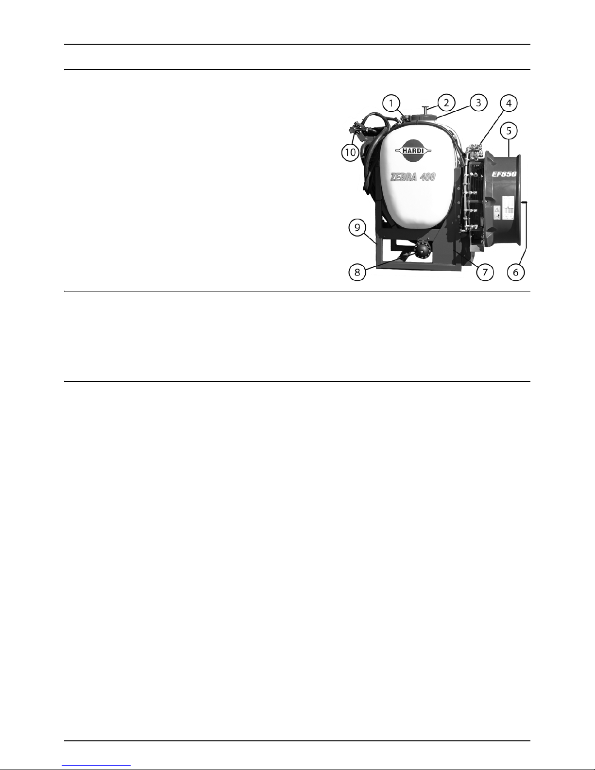
Overview
1. Suction filter
2. Drain valve
3. Main tank lid
4. Nozzle line
5. Fan housing
6. Fan clutch
7. Pump
8. Pulsation damper
9. 3-point quick hitch
10. Operating Unit (If SmartValve, placed beside position 8)
Use of the mistblower
The HARDI MERCURY mistblower is designed for applying crop protection chemicals. The equipment should only be used
for this purpose. The mistblower must not be used for any other purpose.
If there are no special regulations requiring operators to be certified, you must have received the appropriate training on
how to spray crops correctly and safely handling chemicals to avoid unnecessary risks to persons and the environment while
spraying.
Road worthiness
When driving on public roads and other places where the road safety code or where there are other special rules and
regulations for marking and lights on machinery, the machine must be equipped to comply with these regulations.
Page 12
3 - Description
12
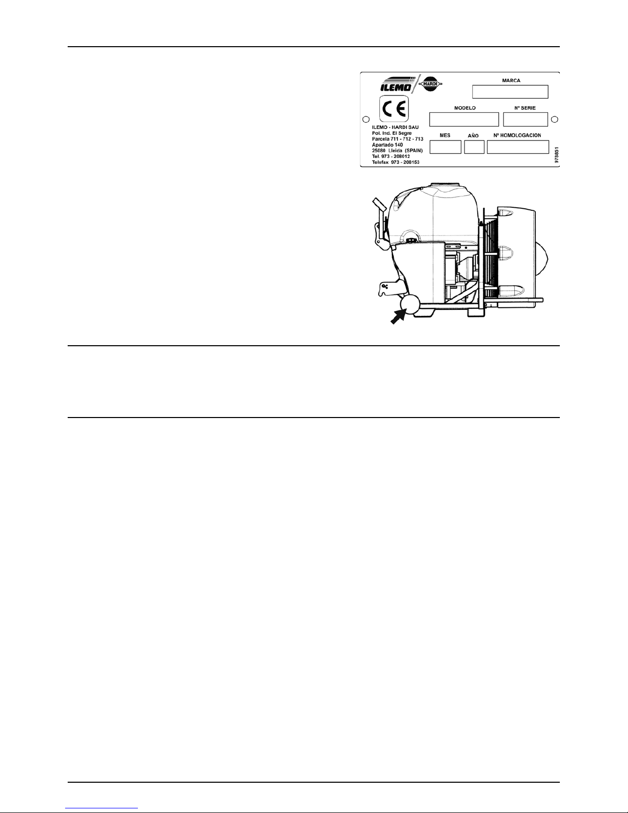
Identification plates
The identification plate is located on the front right-hand side of the
machine and is riveted to the chassis. It indicates the make, model, serial
number, and date of manufacture.
The serial number is also engraved onto the chassis. The number is
found above the identification plate, as indicated in the photograph.
The serial number contains five digits.
Chassis
Manufactured with a tubular profile which provides great durability and resistance to breakages and vibrations.
To protect it from corrosion, it is sanded down and covered with a layer of special paint that contains a polyurethane bicomponent with anti-corrosion additives and protection against ultraviolet rays.
Ta nk
Made of medium-density polyethylene with ultraviolet filters, it has smooth, rounded surfaces that facilitate agitation and
cleaning. Range of volumes: 300, 400, 600 and 800 litres.
Page 13
3 - Description
13
Liquid system
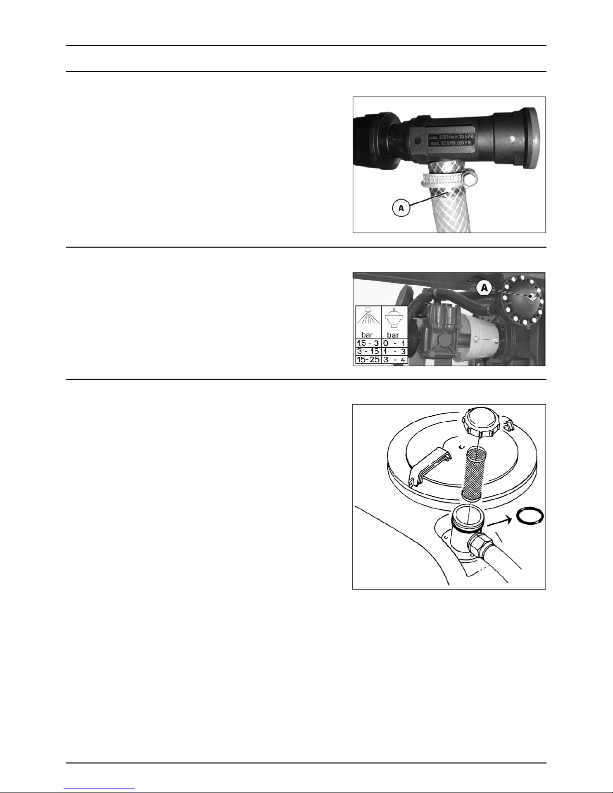
Safety valves
The safety valve protects the liquid circuit against over pressure in the
event of failures or clogged lines.
If the spring-loaded safety valve opens the liquid is lead back to tank via
hose (A).
The safety valve opens at15 bar.
€
DANGER! Do not remove, bypass or block safety valve from the
liquid circuit as this could put your safety at risk.
Pressure pulsation damper
The 3 21 pum p is fitted wit h a pulsatio n damp er on suc tion a nd press ure
sides. The pressure side damper is pressurized. The dampers will reduce
pulsations and secure an even flow from the pump.
The pressure pulsation damper should be inflated to the pressure
shown in the table on top of the pulsation damper (A).
Suction filter
Suction filter is located at the top of the tank.
The filter screen can be checked by unscrewing the lid and pulling the
filter up.
Page 14
3 - Description
14
Tank drain valve
The tank drain valve is operated by the handle located on top of the
tank.
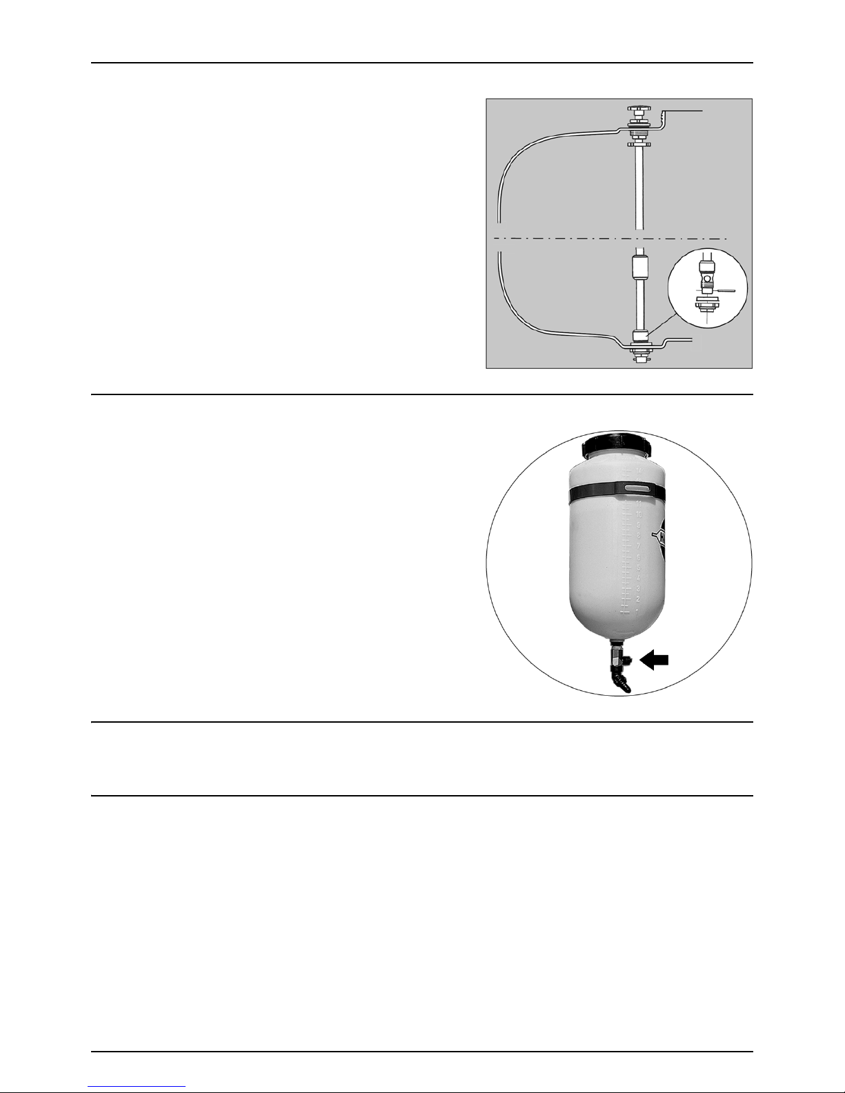
Clean water tank (optional)
The water in this tank is for hand washing, for cleaning of clogged
nozzles etc.
Only fill this tank with clean water from the tap.
The clean water tank is placed on the sprayer’s left side.
Capacity: approximately 15 litres.
€
WARNING! Although the clean water tank is only filled with clean
water, this water must NOT be used for drinking.
Diaphragm pump
Diaphragm pump is model 321/10 (max. 20 bar) with two diaphragms. It works at low pressure and is robustly built. Use only
grease for lubrication. This type of pump is self-priming, works without oil and can run dry as long as necessary.
Piston pump
(Certain countries only)
The robust high-pressure piston pumps are fitted with a single-block crankcase with a large oil capacity for increased
lubrication and cooling; a treated and rectified wrought-steel crankshaft; special cast conrods; horizontal reciprocating
pistons; hydraulic vulcanized sealing rings; chemical-resistant synthetic plungers; individual cylinder heads and stainlesssteel ball check valves. The pump is either UX/70 or UG/102.
Page 15
3 - Description
15
Operating units
The mistblower can be equipped with following types of operating units:
• M70/2
• BS/2
• SV/2 w/ remote control.
• CA
They have two section valves which control the right and left sides. The section valves are remotely controlled from the
tractor cabin.
The type of operating unit available may vary from country to country.
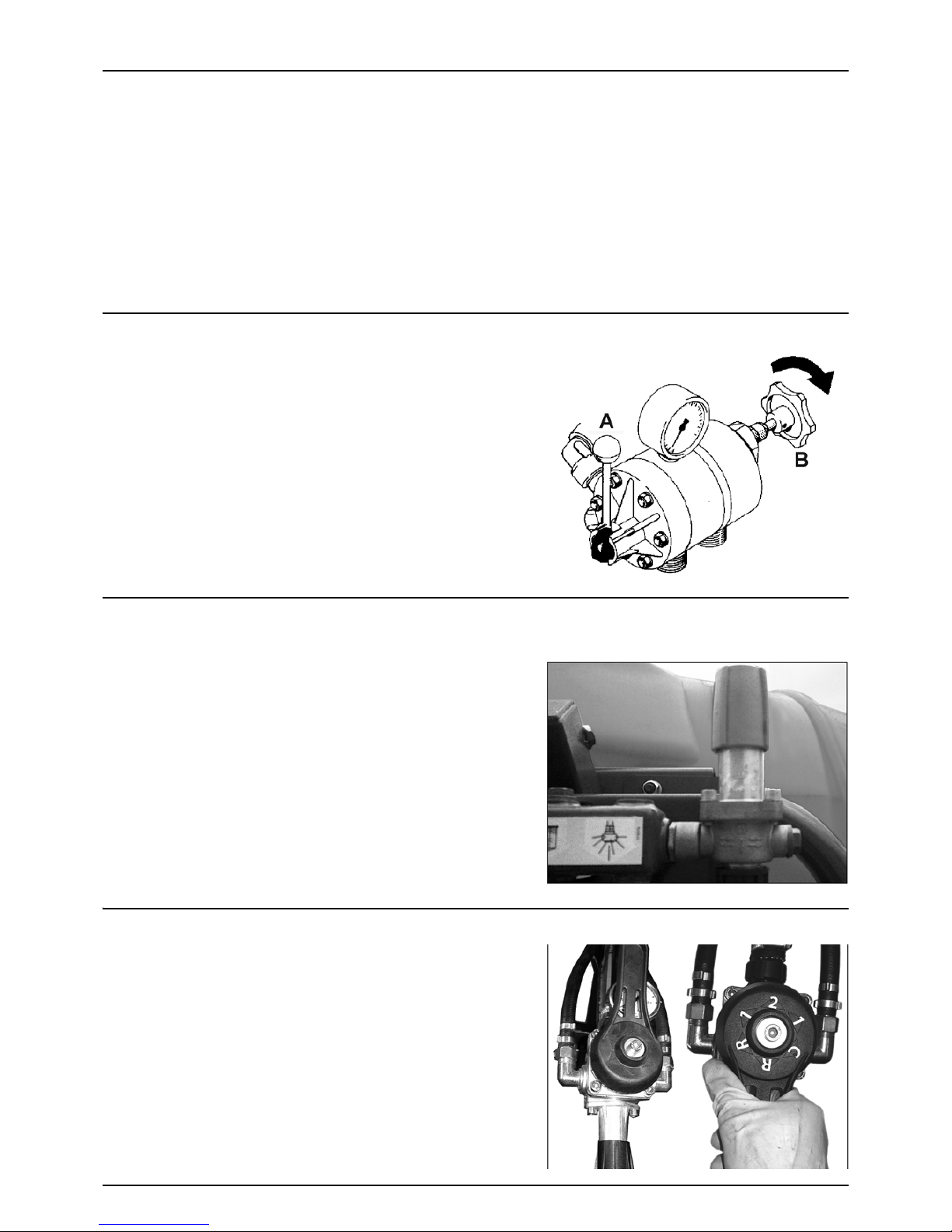
M70/2 operating unit
Manual operating unit including a main on/off valve, a pressure
adjustment valve, a pressure gauge and two section valves for right and
left spray lines.
Lever (A) is main on/off.
Red knob (B) is pressure adjustment valve.
Clockwise = increase.
Anti-clockwise = decrease.
SV/2 operating unit
(Certain countries only)
This high-pressure electric operating unit contains a manual pressure
valve fitted to the machine and a electric control box for opening and
closing the section valves from the tractor cabin.
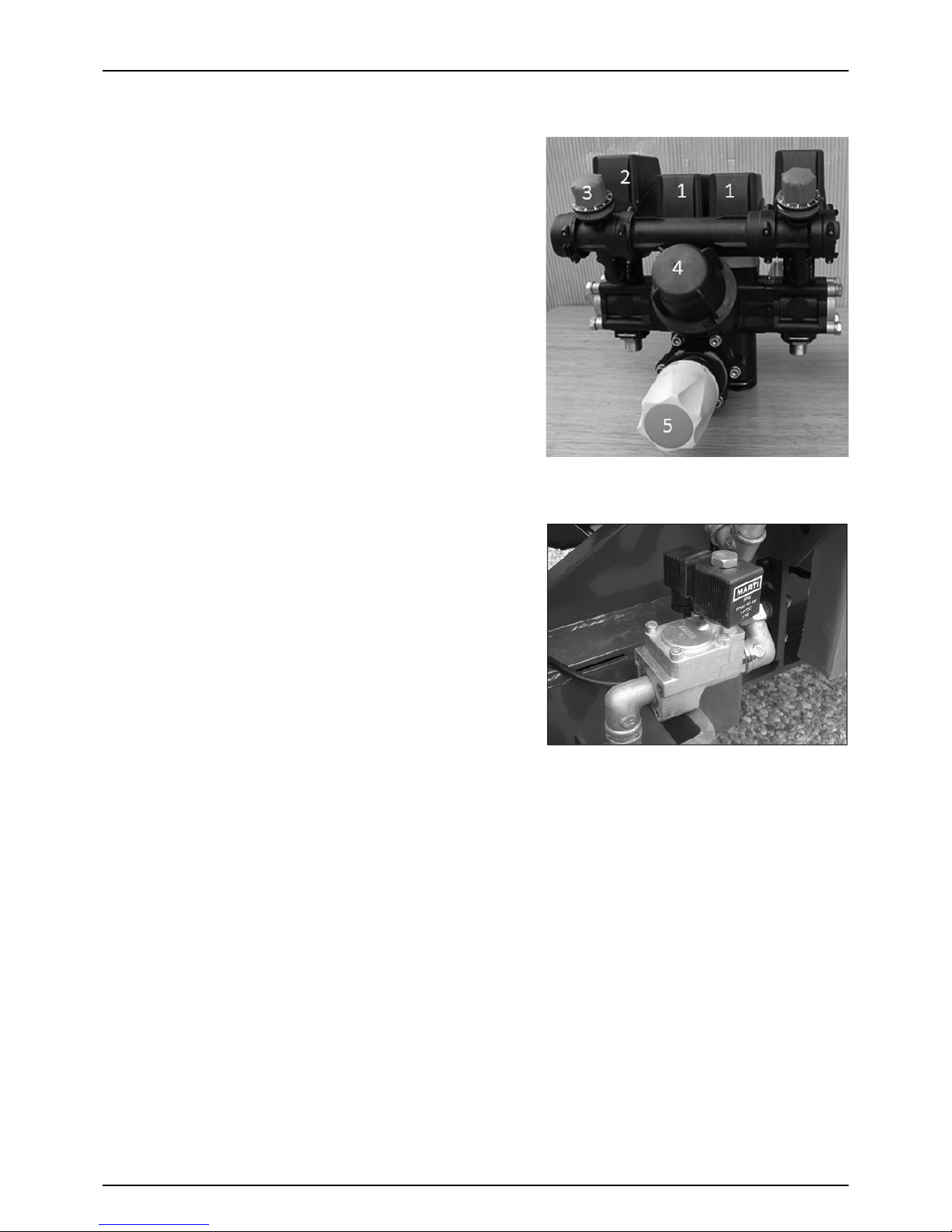
BS/2 operating unit
This high-pressure manual operating unit can be used with piston or
diaphragm pumps. It contains a pressure valve that includes a pressure
gauge and a 5-position single-lever control.
Page 16
3 - Description
16
CA operating unit
1. Section valves
2. Pressure equalisation device
3. Adjustment of pressure equalisation by turning left or right to
increase or decrease pressure
4. Pressure filter
5. Pressure regulation, manual.
Electric section valves
Two electric solenoid valves are used to control spraying to RH or LH
side. The valves are controlled by the operating box in the tractor cabin.
Page 17
3 - Description
17
Air equipment
Axial fan – Technical information
The fans on HARDI ZEBRA mistblowers have been designed with composite blades and their aerodynamic design offer a
higher quantity and better distribution of air, less noise and less power consumption.
€
DANGER! NEVER exceed 540 rpm at the tractor PTO. Exceeding
540 rpm may cause severe damages to the fan and lead to severe
injuries or death!
€
DANGER! Keep away from the air inlets and outlets while the fan
is operating. Foreign objects may be expelled from the air outlet
or a piece of cloth could be sucked into the air inlet. Risk of severe
personal injury or death!
The air kits are the most dangerous part of the machine. Do not repair,
change or modify any of the parts but leave this to your HARDI dealer.
Any repair jobs on air kits in requires qualified technicians.
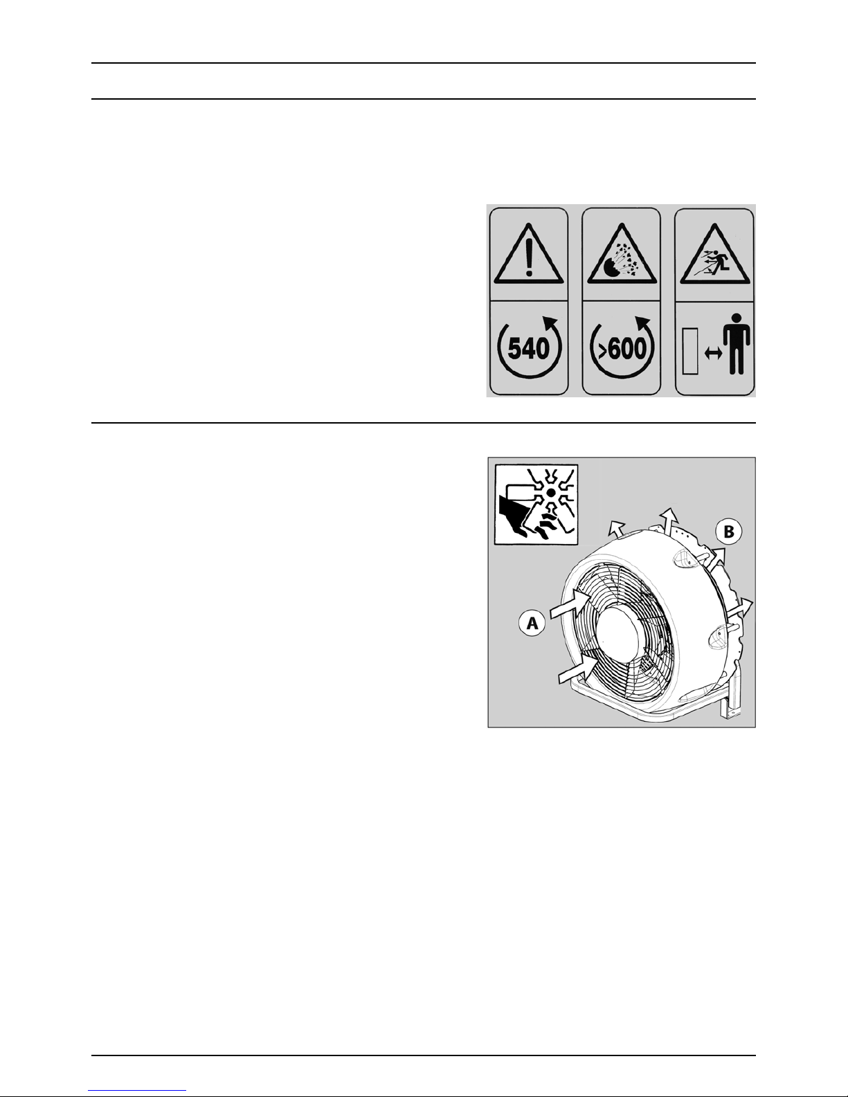
Protection grids
On all axial air kit models protection grids are fitted. They are
fundamental for avoiding accidents and stopping foreign objects from
entering the fan.
A. Air inlet protection grid
B. Air outlet protection grid
€
DANGER! Use of the air kit without protection grids is not
permitted.
€
DANGER! Do not take the protection grids off the equipment
whilst it is in use.
€
DANGER! Do not go near the fan when the equipment is in use if
you are wearing light or loose clothing.
€
DANGER! Never put foreign bodies inside the fan via the grid,
regardless of whether it is in use or not.
€
DANGER! Protect your hearing from fan noise by wearing EN 3521:1992 homologated ear muffs or something similar.
€
DANGER! If you were to notice vibrations or abnormal noise,
switch off the fan immediately.
Page 18

3 - Description
18
Engaging / Disengaging of the turbine fan
The fan is engaged and disengaged by the selector shown.
Always disengage the fan during transport between the farm or filling
location and the orchard.
μ
ATTENTION! when always engage or disengage the fan when the
tractor PTO is stopped.
μ
ATTENTION! Always engage the tractor PTO with the engine at
idle for a smooth start of the fan.
Fan transmission
The fan is driven through the pump shaft directly by a single-speed Vbelt transmission 8 (A).
Check the V-belt tension at every 100 working hours to ensure full
performance. See the section “Maintenance”.
Cannon spout
The ZEBRA is available in a configuration with a cannon spout. This
allows for the entire volume to be directed in one direction. The spout is
horizontally adjustable and can be turned to both sides.
The air outlet of the Cannon is ellipsoidal in order to create a large and
powerful air stream in the upper part for blasting the spray mist a good
distance. This secures a spray distance of 15-20 m horizontally.
A set of 9 nozzles split in 3+3+3 each has its individual non-drip valve as
well as ON/OFF valve in the pressure manifold. This in combination with
the vertical and horizontal adjustments enables the Cannon to be set
and calibrated for any spray job.
A
B
A
Page 19

3 - Description
19
Vine sprayer
The ZEBRA is available in a configuration with spouts for spraying vines.
The spouts can be easily orientated, so that efficient air and spray mist
are applied on both sides of the vine plant.
Applying the precise dose is easily chosen by the manifold valves and
pressure regulator.
Whenever mixing of spray liquid is done during transport, the turbine
fan can be disengaged.
The spray boom has a total width of 4.5 meters, and it can be adjusted
0.5 meters in height.
Pneumatic system
The pneumatic system operates on low pressure and produces a high air
speed in the spout to break up the spray film and create a very fine
turbulent mist. Via the atomizers in the spout, the mist is distributed
uniformly in the shape of a fan.
Four types of spouts are available depending on boom type:
A. Cannon with 1 outlet
B. Spout with 2 outlets
C. Spout with 3 outlets
D. Spout with 4 outlets
Ceramic discs are used to control the flow rate. This disc has two
positions. If the disc is placed so the flow enters through its flat side, this will allow less to go through than if it enters through
the cone-shaped side.
Hydro-pneumatic system
The hydro-pneumatic system operates on a medium to high pressure.
This system takes advantage of the great amount of turbulence in the
cone-shaped low-volume nozzle and distributes the spray liquid
correctly. The air gets to the spout at high speed and this spreads the
water in the shape of a fan.
There are two types of spout, with three or five nozzles. These two
spouts cannot be used together.
E. Spout with 3 nozzles
F. Spout with 5 nozzles
Page 20

3 - Description
20
Page 21

21
4 - Start up
General information
Important Information
Before using the machinery, it is recommended that you read the instructions to obtain best results and avoid operational
problems.
Unloading the mistblower from the truck
When loading or unloading the mistblower to/from a lorry by using a
lever and pulley or a crane, use the suspension points shown on the
diagram and make sure the straps used are strong enough.
€
DANGER! Nobody must stand below or next to the machine
during loading or unloading.
Before starting up for the first time
Although the surface of the metallic parts of the mist blower have been coated with a strong, protective product, we
recommend you apply a layer of anti-corrosion oil (e.g. CASTROL RUSTILLO or SHELL ENSIS FLUID) to all metal parts to avoid
chemical products discolouring the enamel, as well as to ease future cleaning.
μ
ATTENTION! This treatment should be repeated whenever the protective film wears off.
Counterweights
Check if it is necessary to place a counterweight on the front of the
tractor, to increase the stability and steering performance.
Page 22

4 - Start up
22
Mechanical connections
Operator safety
1. Always STOP THE ENGINE before attaching the transmission shaft to the tractor P.T.O. - most tractor P.T.O. shafts can be
rotated by hand to facilitate spline alignment, when the engine is stopped.
2. When attaching the shaft, make sure that the snap lock is FULLY ENGAGED - push and pull the shaft until it locks.
3. Always keep protection guards and chains intact and make sure that it covers all rotating parts, including CV-joints at
each end of the shaft. Do not use without protection guard.
4. Do not touch or stand on the transmission shaft when it is rotating - safety distance: 1.5 meter. Also NEVER cross over
a rotating P.T.O. shaft to reach the other side of the sprayer.
5. Prevent protection guards from rotating by attaching the chains allowing sufficient slack for turns.
6. Make sure that protection guards around the tractor P.T.O. and the implement shaft are intact.
7. Always STOP THE ENGINE and remove the ignition key before carrying out maintenance or repairs to the transmission
shaft or implement.
€
DANGER! ROTATING TRANSMISSION SHAFTS WITHOUT PROTECTION GUARDS ARE FATAL.
P.T.O. installation
Initial installation of the driveshaft may involve having to cut the axle to
adapt it to the tractor to which it will be hitched. To hitch it for the first
time, proceed as follows:
1. Attach the mistblower to the tractor in such a way that the
distance between the PTO shaft and the mistblower pump is the
shortest possible.
2. Stop the engine and remove the ignition key.
3. If the driveshaft needs to be shortened, pull the two parts of the
shaft apart. Fit the two parts of the shaft, one to the tractor and the
other to the mistblower crankshaft and measure out the length
that needs to be removed. Mark the protection guards.
μ
ATTENTION! The shafts must always have a minimum overlap of
one third of their working length.
4. Cut both parts equally, using a saw. File the profiles afterwards to
remove burrs.
5. Grease the profiles and reassemble male fitting and female fitting.
6. Fit the shaft to the tractor PTO and to the mistblower pump shaft.
Page 23

4 - Start up
23
7. Place the input part towards the tractor. Fit the chains to prevent
the protection guards from rotating with the shaft.
μ
ATTENTION! To ensure long life of the driveshaft and prevent
possible damage to the equipment, try to avoid working at
angles of more than 15°.
Connecting the mistblower
The mistblower is designed for three point suspension and is factory
equipped with 22 mm pivots (category I).
Connect as follows:
1. Connect the lower links ball ends of the tractor to the mistblower
lower link pins.
2. Fit the linch pins to secure the lower links.
3. Attach the top link to tractor and mistblower and adjust it by hand.
Secure with a linch pin.
4. Lift the mistblower to working height.
5. Ajdust the top link until the equipment is completely
perpendicular to the ground.
To detach the mistblower:
1. Lower the tractor’s lower links with the hydraulic lever until the equipment is touching the ground.
2. Loosen and remove the top link pin.
3. Remove the top link.
4. Lower the lower links and completely detach the mistblower.
5. Drive the tractor away slowly.
±
WARNING! The tractor’s hydraulic lower links should be moved very gently to prevent damages or tipping over.
Page 24

4 - Start up
24
Top link clevis for snap coupler (600 litre model only)
If required a top link clevis (ref. no. 637348) can be mounted on the
frame of the NK 600 litre model to enable the snap coupler to be
connected on the top link of the mistblower.
1. Loosen the 4 bolts which fix the top link to the tank frame.
2. Replace this top link with the adapter clevis and fasten it to the
frame with the 4 bolts.
Page 25

4 - Start up
25
Electrical connections
General information
If your equipment includes an electrical component, please note the
following information to correctly connect the equipment and to
prevent problems when working.
The voltage required by the electrical components is 12 volts (V ).
Before connecting any component, make sure that the polarity is
correct.
Red wire = 12 V positive (+)
Black wire = negative (-)
The connectors assembled on the electric components comply with the
standards for the majority of modern tractors.
If your tractor has another type of power supply connector, the supplied
connector will need to be removed and adapted to the tractor connector.
Installing the basic electrical control box
Find a suitable location in the tractor cabin where the control box can
be fitted and operated comfortably. It is recommended that you place it
to the right of the driver’s seat.
μ
ATTENTION! The control box must be properly attached to
prevent vibrations and damages.
The connector is an universal type with removable adaptor cap (A) and
it should be able to be connected to any tractor.
As an emergency solution, remove the connector and splice the wires
directly to the battery.
±
WARNING! Always remember: Red wire (+) Black wire (-)
÷
NOTE! Always replace the spare fuse again so a new fuse is
available for future use.
-
Blue
+
Brown
Page 26

4 - Start up
26
Page 27

27
5 - Operation
Liquid and Air Circuits
Filling/washing location requirements
When filling the mistblower with chemicals and water it is important to avoid spot contamination by spray chemicals in
order to protect the subsoil water resources.
A. If the mistblower is always filled at the same place, a special filling/washing location should be established. This should
have a hard, liquid-impenetrable surface (e.g. concrete) securing against seepage and edges securing against run-off
to the surrounding areas. The place should be drained to an adequate receptacle (e.g. slurry tank or similar).
Any spillage or washings should be retained and diluted in order to be distributed on a larger area to ensure minimal
environmental impact and avoid build-up of larger chemical concentrations at one spot.
If no other requirements of distances exist, the following general recommendation of distance could be used. Not
closer than:
1) 50 metres from public water supplies for drinking purposes,
2) 25 metres from non-public water supplies for drinking purposes, treatment sumps and cesspools of drainage
systems, and
3) 50 metres from surface water (watercourses, lakes and coastal waters) and from nature reserves.
B. Alternatively the mistblower can be filled in the field where the spraying is to take place. If so, choose a different
location for each refilling.
C. If no other requirements of distances exist, the filling should not be established closer than:
1) 300 metres from public or non-public water supplies for drinking purposes and
2) 50 metres from surface water (watercourses, lakes and coastal waters), treatment sumps, cesspools of drainage
systems, and nature reserves.
μ
ATTENTION! Legislation and requirements vary from country to country. Always follow local legislation in force at any
time.
÷
NOTE! It is the responsibility of the mistblower owner/operator to comply with all relevant legislation. HARDI cannot
undertake any responsibilities for incorrect operation and use.
Filters
Clean filters ensure:
• Sprayer components such as valves, diaphragms and operating unit are not hindered or damaged during operation.
• Nozzle blockages do not occur whilst spraying.
• Long life of pump. A blocked suction filter will result in pump cavitation.
Page 28

5 - Operation
28
Suction filter
The main filter protecting sprayer components is the suction filter at the
top of the tank.
Check it regularly and clean if needed.
Ensure that the O-ring on the filter housing is in good condition and
lubricated.
Pressure filter
Pressure filters will catch any remaining impurities and prevent nozzles
clogging. To avoid blockage of those filters it is very important to check
them regularly and clean them after each spray job to avoid chemical
residues to deposit and block
±
WARNING! Wear appropriate personal protection when checking
pressure filters. As a minimum gloves and face shield.
Page 29

5 - Operation
29
Diaphragm pumps
The maximum number of revolutions when in use is 540 r.p.m. It is selfpriming and can be run dry. The pump is fitted with 2 diaphragms.
μ
ATTENTION! Be careful to make sure the pump is perfectly
greased when it is to be used.
μ
ATTENTION! See section “Maintenance” regarding lubrication
intervals.
UX/70 and UG/102 piston pumps
This pump is a 3-cylinder piston pump. The max. number of revolutions
when in use is 540 rpm.
€
WARNING! Do NOT let piston pumps run dry for more than 30
seconds. If the pump is running dry for longer time the pistons
and liners will overheat and be destroyed. Always prime the
pump before use.
μ
ATTENTION! Check oil level before start up. Also see the section
“Maintenance” regarding oil change intervals.
÷
NOTE! This pump model is used in certain countries only.
Filling the main tank
The tank is filled with water through the filling hole by removing the lid located on the top of the tank. The water used should
be as clean as possible to obtain best results.
Fill the tank using the filter to prevent impurities from entering the tank. For greater filling capacity, an overhead tank can be
used.
The tank should be filled to a third of its capacity with clean water before adding the chemical product. Always follow the
instructions given on the product label!
μ
ATTENTION! Always fill through the tank strainer to prevent impurities from entering the tank.
€
DANGER! Do not place the filling hose inside the tank. Keep it out
of the tank at all times and only point it towards the filling hole. If
the pressure hose were placed inside the tank and there was a
drop in water supply pressure, the chemical product could be
syphoned back and contaminate the water supply lines, plant
and well.
€
WARNING! If spray liquid is left in the tank, for safety reasons all
valves must be shut.
μ
ATTENTION! The water supply line should be provided with a check valve as additional safety precaution. Follow local
legislation in force at any time.
μ
ATTENTION! The water supply should be provided with a meter to avoid spillage by over-filling. Follow local
legislation in force at any time.
Page 30

5 - Operation
30
Adjustment of operating unit M70
1. Turn main on/off handle (1) to off position A.
2. Set all hand levers on the distribution valve (2) to spraying position
A.
3. Put the tractor in neutral and set the engine revolutions and
thereby the number of revolutions of the pump corresponding to
the intended travelling speed. Remember the number of
revolutions on the P.T.O.must be kept between 300-600 r/min.
4. Turn main on/off handle (1) to spraying position B.
5. Now turn the pressure regulating valve (3) to until the required
pressure is indicated on the pressure gauge.
6. Operating the control unit while driving: To close the entire boom,
turn the handle (1) to position A. This takes the pressure off the
pump. The liquid will then return to the tank via the return system.
The diaphragm anti-drip valves ensure instantaneous closing of all nozzles. In order to close part of the boom, move
lever (2) of the distribution valve to position B (off position) for the section or sections to be closed. Note that the
pressure will rise and readjustment will be necessary.
Adjustment of operating unit SV/2
This high-pressure electric operating unit can be assembled with piston
or diaphragm pumps.
It consists of a manual pressure valve that has a pressure gauge. To raise
the pressure, turn the red handle A clockwise. To lower it, turn it anticlockwise.
The two section valves are remote controlled by two solenoid valves
activated via a control box in the tractor cabin.
Adjustment of operating unit BS/2
This high-pressure manual operating unit can be used with piston or
diaphragm pumps.
To raise the pressure, turn the black handle. To raise the pressure, turn
the handle clockwise. To lower it, turn it anti-clockwise.
The direction of the flow can be selected with the control.
The different positions are embossed on the lever.
±
WARNING! As this operating unit is assembled on the tractor
beside the operator, ensure that there is no leakage as otherwise
your safety may be at risk.
R=Free return
C=Agitation only
1 = One open spray zone + active agitation
2 = Two open spray zones + active agitation
Page 31

5 - Operation
31
Section valves
The solenoid valves are located at the back of the equipment, next to
the pressure filter.
The sections are instantly opened and closed with these solenoid valves.
Draining the main tank
200 and 300 l tanks:
To empty the tank via the drain valve, turn the pin on the lower righthand side of the auxiliary tank. To close it again, turn the pin again and
the valve will close automatically.
400, 600 and 800 l tanks:
Top operated tank drain
A. open
B. Close
±
WARNING! Do not forget to use protective clothing and gloves
when doing this.
Agitation
The dual-nozzle agitation system injects the chemical product at high
pressure from the pump inside the tank creating a turbulence that mixes
the product with the water to a uniform liquid.
The standard agitation has 2 mm venturi nozzles. The venturi nozzle (B)
allows an efficient agitation of the main tank content.
Page 32

5 - Operation
32
Engaging the turbine fan
When you are going to work with a spray gun, or just need agitation in
the main tank, the fan can be disengaged by the lever.
The lever is located behind the pump. When the lever (A) is in the centre
position, the fan is disengaged.
μ
ATTENTION! The PTO, pump and fan must stand completely still,
before the fan is engaged or disengaged.
μ
ATTENTION! To avoid shock loading the fan transmission, the
tractor engine must run idle before engaging the PTO.
Nozzles
The standard nozzle can be closed individually by turning them 90º.
When open the direction can be adjusted within a range of +/- 15º.
A non-drip valve (A) is fitted to avoid chemical spillage the sections are
shut off.
The nozzle type (B) are a hollow cone nozzle, also known as ATR. They
are colour-coded and the working range is 5-15 bar.
This type of nozzle can also be used with hydro-pneumatic equipment.
μ
ATTENTION! It is not advisable to exceed 15 bar with ATR nozzles
as the droplets would be too small, and the liquid will either
evaporate under hot conditions or be lost due to wind drift.
New picture of fan on/off lever
A
B
Page 33

5 - Operation
33
Cleaning
General info
In order to derive full benefit from the sprayer for many years the following service and maintenance program should be
followed.
μ
ATTENTION! Always read the individual paragraphs. Read instructions for service/maintenance jobs carefully before
starting on the job. If any portion remains unclear or requires facilities which are not available, then for safety reasons
please leave the job to your HARDI dealer’s workshop.
μ
ATTENTION!
Clean sprayers are safe sprayers.
Clean sprayers are ready for action.
Clean sprayers cannot be damaged by pesticides and their solvents.
Guidelines
1. Read the whole chemical label. Take note of any particular instructions regarding recommended protective clothing,
deactivating agents, etc. Read the detergent and deactivating agent labels. If cleaning procedures are given, follow
them closely.
2. Be familiar with local legislation regarding disposal of pesticides washings, mandatory decontamination methods, etc.
Contact the appropriate authority if you are in doubt.
3. Pesticide washings can usually be sprayed out on the field just sprayed or at a suitable cultivated area. Avoid emptying
the washings at the same spot every time and keep sufficient distance to the water environment. You must prevent
seepage or runoff of residue into streams, water courses, ditches, wells, springs, etc. The washings from the cleaning
area must not enter sewers. Alternatively the washings can be retained in an appropriate receptacle, diluted and
distributed over a larger cultivated area - see also Filling/washing location requirements on page 27.
4. Cleaning starts with the calibration, as a well calibrated sprayer will ensure the minimal amount of remaining spray
liquid.
5. It is good practice to clean the sprayer immediately after use and thereby rendering the sprayer safe and ready for the
next pesticide application. This also prolongs the life of the components. It is strongly advised to perform an internal
cleaning of the sprayer when high concentration of acids or chloride are present in the active ingredients, or if the spray
liquid is corrosive. For the best result use a cleaning agent recommended by Hardi, e.g. AllClearExtra.
6. It is sometimes necessary to leave spray liquid in the tank for short periods, e.g. overnight, or until the weather becomes
suitable for spraying again. Unauthorized persons and animals must not have access to the sprayer under these
circumstances.
7. If the product applied is corrosive, it is recommended to coat all metal parts of the sprayer before and after use with a
suitable rust inhibitor.
8. The sprayer must always be parked under roof to avoid rain washing off pesticides and build-up of spot contamination
in the soil. If parked outside the sprayer should be parked on the filling/washing location in order to retain possible
pesticides.
Cleaning and maintaining the filters
Clean filters ensure:
• Mistblower parts, such as the valves, diaphragms and operating units, are not blocked or damaged during use.
• Nozzles are not blocked during spraying.
The pump has a long service life. A clogged suction filter will result in pump cavitation. The main filter that protects the
mistblower parts is the suction filter. Check it regularly.
Page 34

5 - Operation
34
Cleaning the tank and liquid system
1. Dilute remaining spray liquid in the tank with at least 10 parts of water and spray the liquid out in the crop/orchard just
sprayed.
2. Select and use the appropriate protective clothing. Select detergent suitable for cleaning and suitable deactivating
agents if necessary.
3. Rinse and clean mistblower and tractor externally. Use detergent if necessary.
4. Remove tank and suction filters and clean. Be careful not to damage the mesh. Replace suction filter top. Replace filters
when the mistblower is completely clean.
5. With the pump running, rinse the inside of the tank. Don’t forget the tank roof. Rinse and operate all components and
any equipment that have been in contact with the chemical. Before opening the distribution valves and spraying the
liquid out, decide whether this should be done in the field again or on the soakaway.
6. After spraying the liquid out, stop the pump and fill at least 1/5 of the tank with clean water. Note that some chemicals
require the tank to be completely filled. Add appropriate detergent and/or deactivating agent, e.g. washing soda or
Triple ammonia.
7. Start the pump and operate all controls enabling the liquid to come into contact with all the components. Leave the
distribution valves until last. Some detergents and deactivating agents work best if left in the tank for a short period.
Check the label.
8. Drain the tank and let the pump run dry. Rinse inside of the tank, again letting the pump run dry.
9. Stop the pump. If the pesticides used have a tendency to block nozzles and filters, remove and clean them
immediately.
10. Replace all the filters and nozzles and store the mistblower. If, from previous experiences, it is noted that the solvents
in the pesticide are particularly aggressive, store the mistblower with the tank lid open.
μ
ATTENTION! It is advisable to increase the forward speed (double, if possible) and reduce the pressure to 1.5 bar (20
psi) when spraying diluted remaining liquid in the field just sprayed.
μ
ATTENTION! If a cleaning procedure is given on the chemical label, follow it closely.
μ
ATTENTION! If the mistblower is cleaned with a high pressure cleaner, lubrication of the entire machine is
recommended.
Unexpected interruptions
If you have to stop a treatment unexpectedly, due to bad weather for example, and there is still some liquid in the tank, we
recommend you rinse the tank, operating unit and pipes.
• Close the nozzles and switch off the PTO.
• Close the suction filter valve and open the filter.
• Immediately put clean water down the suction hose which goes straight to the pump and open up the nozzles.
• Follow the procedure until clean water comes out of the nozzles.
• Stop the pump and put the suction filter back in place.
Page 35

35
6 - Maintenance
Lubrication
General info
Always store lubricants clean, dry and cool - preferably at a constant temperature - to avoid contamination from dirt and
condensed water. Keep oil filling jugs, hoppers and grease guns clean, and clean the lubricating points thoroughly before
lubricating. Avoid skin contact with oil products for longer periods.
Always follow the quantity recommendations. If no quantity is recommended, feed lubricator till new grease becomes
visible.
Pictograms in lubrication & oiling plans designate the following:
1. Lubricant to be used (see “Recommended lubricants”).
2. Recommended intervals (hours).
μ
ATTENTION! If the sprayer is cleaned with a high pressure cleaner,
lubrication of the entire machine is recommended.
Recommended lubricants
Transmission shaft
The universal joints and needle bearings should be lubricated with
grease. At the points shown, you should do (A) every 8 working hours
and the profile tubes (B) every 20 working hours.
BALL BEARINGS:
Universal Lithium grease, NLGI No. 2
SHELL RETINAX EP2
CASTROL LMX grease
SLIDE BEARINGS:
Lithium grease enhanced with molybdenum or grafite disulphate
SHELL RETINAX HDM2
CASTROL MOLYMAX
OIL LUBRICATION:
TOTAL Transmission TM
SAE 80W/90
Castrol EPX 80W/90
SHELL Spirax 80W/90
Mobil Mobilube 80W/90
OIL LUBRICATION:
SAE 30W
SAE 20W/50
Page 36

6 - Maintenance
36
Service and maintenance intervals
General information
The maintenance and replacement intervals of the elements listed as follows will depend on the conditions under which
the mistblower will be used, and hence impossible to assess.
±
WARNING! If you do not feel confident in carrying out some of the maintenance jobs described below, then contact
your HARDI dealer’s workshop for assistance.
Every 10 working hours
1. Clean the suction filter
2. Clean the pressure filters
3. Clean/inspect the nozzles
4. Check for leaks in the liquid circuit
5. Check for leaks on the suction circuit
Every 50 working hours
1. Carry out the checks mentioned above
2. Check the pressure in the pressure pulsation damper
3. Check/Grease the transmission shaft
4. Check/grease the mechanical clutch
5. Grease the diaphragm pump
6. Check oil level on piston pumps
Every 100 working hours
1. Carry out the checks mentioned above
2. Check/adjust the fan transmission V-belts tightness
Every 150 working hours
1. piston pump oil change
Every 1000 working hours
1. Carry out the checks mentioned above
2. Inspect the transmission for proper functioning, ballance etc.
3. Check the fluid circuit for tightness
4. Inspect the pump for proper functioning
5. Check the pressure gauge accuracy.
6. Inspect the fan unit for damages and proper functioning.
Page 37

6 - Maintenance
37
Every 10 working hours – Suction filter
To service the suction filter, proceed as follows:
1. Unscrew the red cap anti clock-wise
2. Remove the filter screen and clean it with a soft bruch and clean
water.
3. Insert the filter screen again
4. check and clean the O-ring and cap
5. lubricate the O-ring with oil or grease if necessary
6. fit the cap again and tighten hand-tight
μ
ATTENTION! Insufficiently maintained filters leads to numerous
unwanted stops during a working day.
μ
ATTENTION! Lubricate the seal lightly with oil or grease every
time the filter is dismantled to ensure the seal will slide correctly
in place and seal.
μ
ATTENTION! A broken or leaking O-ring or sealing in the suction
circuit leads to suction of false air and huge vibrations and
pressure pulsations.
Every 10 hours of operation – Pressure filters
o remove the pressure filter, unscrew the filter housing to inspect and
clean the filter. When you reassemble the filter, grease the o-ring.
There are different mesh sizes. See the section ‘Technical specifications
– Filters and nozzles’.
Page 38

6 - Maintenance
38
Every 10 working hours – Nozzles
To clean or replace the nozzles, use a spanner to undo the nut (D).
Remove the nozzle and clean it with air, water or a toothbrush.
μ
ATTENTION! Never use a piece of wire or a needle as this could
cause irreparable damage to the nozzle.
If any of the nozzles leak when closing the spray section valve, the nondrip diaphragm should be replaced (E). The nozzles should be replaced
when their unit flow varies more than 10%. Worn or damaged nozzles
may cause crop damages or insufficient results.
Every 50 working hours - Pressure pulsation damper
The 3 21 pum p is fitted wit h a pulsatio n damp er on suc tion a nd press ure
sides. The pressure side damper is pressurized. The dampers will reduce
pulsations and secure an even flow from the pump.
The pressure pulsation damper should be inflated to the pressure
shown in the table on top of the pulsation damper (A).
Every 50 working hours - Diaphragm pump
Grease the pump after every 50 working hours or once a month,
through the grease nipple located at the crankshaft end. The grease is
distributed through the crankshaft to ball bearings, connecting rods, etc.
±
WARNING! A lack of grease in the pump could cause it to
overheat and destroy moving parts.
Page 39

6 - Maintenance
39
Every 50 working hours - piston pumps
Check the oil level at regular intervals. This must be between the
maximum and minimum marks on the dipstick. The factory always
supplies a full pump.
Change the oil after the first 50 working hours. The subsequent changes
should be carried out every 150 hours or once a year.
Every 100 working hours - V-belt adjustment
Check/adjust the V-belt (A) tightness as follows:
1. Loosen the 2 x 3 fan retaining bolts either side.
2. Loosen the counter nuts of the adjustment screw either side.
3. Adjust the V-belt tightness on the two adjustment screws either
side, until the V-belts has obtained a suitable tightness. Tighten the
bolts equally in both sides.
4. The V-belt should yield 10-15 mm by a force of 10 N (1 kg) halfway
between the two pulleys.
5. Tighten the counter nuts again.
6. Tighten the 2 x 3 fan retaining bolts either side again.
μ
ATTENTION! Over-tightening the V-belts will increase load, wear
and tear on the pump and fan parts and bearings.
Every 150 working hours - Piston pump oil change
Change the oil afte the first 50 working hours and then every 150 hours
or once a year - which ever comes first.
Run the pump until it has reached normal operating temperature before
draining the oil
μ
Clean the pump and area around dip stick, and drain plug before
changing the oil
Fill with fresh oil to the level is between min. and max. on the dip stick.
Run the pump for a few minutes and verify the oil level again. Top up if
necessary.
A
Page 40

6 - Maintenance
40
Occasional maintenance
Diaphragm pump
Replacement of valves and diaphragms. The procedure is similar for both models 321 and 363 pump.
321 pump
1. Dismantle the valve cover.
2. Replace the valves and O-rings.
3. Undo the bolt and replace the diaphragms.
4. At this stage make sure that the diaphragms are fitted in the
correct position. The part indicated must be facing outwards.
5. Tight the screw which is supporting the diaphragm at the
maximum with 60 Nm.
6. Lubricate seals and fit the valves. Take care not to fit valves on
upside-down.
7. Fit the diaphragm cover again. When the cover is placed on top of
the diaphragm, and before the bolts are tightened, turn the
crankshaft one turn to seat the diaphragm correctly in the cover
Torque settings for the 321 are:
Crankcase: 60 Nm / 44.4 lbft
Crankshaft: 70 Nm / 51.8 lbft
Diaphragm screws: 60 Nm / 44.4 lbft
Piston pump - Plunger tightness
When you detect a continuous leakage of liquid from the bottom of the
pump cylinders, it may be necessary to replace the pump plungers due
to wear.
μ
ATTENTION! Before replacing them, be aware that the leather
gives over time in the sleeve and dripping can occur. If this
happens, tighten the leather tensor and the liquid will stop
dripping.
Page 41

6 - Maintenance
41
Piston Pump - Plunger replacement
To replace the plungers, proceed as follows:
1. Remove the two top nuts of the pressure manifold and the six front
nuts and remove the manifolds and the cylinder heads.
2. Spread grease or oil on the new sleeves and place the plunger
inside.
3. On one side, the sleeves have a groove that should be facing the
cylinder heads.
4. Couple the sleeves with the plunger in the piston.
5. Assemble the leather tensor. Tighten the tensing nut fully.
6. Stretch the leather by hand until reaching the limit and then turn
it a quarter of a turn with key (if you have torque wench, tighten
the torque to 2.5 – 3 kg pressure - approximately 30 Nm).
μ
ATTENTION! Before replacing it, be aware that the leather gives
over time in the sleeve and dripping can occur. If this happens,
tighten the leather tensor and the liquid will stop dripping.
7. Fit the cylinder heads and place the nuts without over-tightening
them.
8. Grease the joints of the six valves before reassembling them.
9. Place the pressure valves on the cylinder heads and the suction
valves on the lower chamber.
10. Fit the pressure and suction chambers, and tighten the nuts with a
torque setting of 3.5 Nm. The tightening pressure is 30 Nm (3 kg).
11. Tighten all the other nuts simultaneously until the whole unit is
tight and compact.
Page 42

6 - Maintenance
42
Off season storage
Winter storage
At the end of the season, some extra time should be dedicated to the equipment before storing it during the winter time.
It is recommended you store it in a place where it cannot be affected by freezing temperatures. Put at least 10 litres of antifreeze covering 33% of the inside of the tank and turn the pump for a few minutes so that the entire circuit is filled by the
solution.
As anti-freeze is an oily solution it also avoids the hoses and all the non-metallic parts from drying up during the period of
time that the equipment will be out of use.
Preparing the equipment for use after storage
After storage, the equipment should be prepared well, thus guaranteeing it is in good condition for the new season. To do
this correctly, follow the steps set out below:
1. Take off the protective canvas cover if you had put one on.
2. Fit the pressure gauge again. Change the old Teflon.
3. Connect the equipment up to the tractor, including the electric cables and hydraulic hoses.
4. Check the hydraulic functions.
5. Drain the remaining anti-freeze from the tank.
6. Completely rinse out the liquid circuit with clean water.
7. Fill the tank with clean water and check all its functions.
Page 43

43
7 - Fault finding
Operational problems
General info
Operational incidents are frequently due to the same reasons:
1. A suction leakage reduces the pump pressure and may interrupt suction completely.
2. A clogged suction filter may damage suction or interrupt and prevent the pump from running normally.
3. A clogged pressure filter increases pressure in the fluid system in front of the pressure filter. This may blow the safety
valve.
4. Clogged In-line or nozzle filters increase pressure in the pressure gauge but decrease pressure at the nozzles.
5. Impurities sucked by the pump may prevent the valves from closing correctly, thus reducing the pump flow.
6. A bad reassembly of the pump elements, especially the diaphragm covers, causes air intakes or leaks and reduces the
pump flow.
7. A badly charged or faulty battery causes failures and misbehaviour in the electrical system.
Therefore ALWAYS check
1. Suction and pressure filters, as well as nozzles, are clean.
2. Hoses for leaks and cracks, paying particular attention to suction hoses.
3. Gaskets and O-rings are present and in good condition.
4. Pressure gauge is in good working order. Dosage accuracy depends on it.
5. Operating unit functions properly. Use clean water to check.
6. The good condition of the tractor battery and its connectors.
Page 44

7 - Fault finding
44
Fluid circuit
Blower unit
FAULT PROBABLE CAUSE POSSIBLE SOLUTION
On activating, the system doesn’t spray Air in the suction line. Check the suction filter o-ring.
Check the suction tube and fittings.
Check the assembly of the pump crankcase covers and
diaphragms.
Air in the system. Prime the pump by filling the hose with water
Suction or pressure filters blocked. Clean the filters
Check the suction fitting and make sure that it is not too close to the
outlet on the tank floor.
Loss of pressure Incorrect assembly The safety valve’s spring is damaged.
The suction fitting is blocked
The suction filter is clogged
Pump valves clogged or worn Check for obstructions and wear
Defective pressure gauge Check for dirt in the intake
Pressure jumps Filters clogged Clean the filters. Clean with clean water. If powdered product is
being used, check that agitation is on.
Worn nozzles Check that the air flow does not exceed 10%.
Tank suction clogged Check the suction tube
Air suction Reduce revolutions in the PTO
Increase in pressure Pressure filters blocked Clean the filters
Foam formed Air in the circuit Check the o-rings, gaskets, hoses and suction fittings
Excessive agitation. Reduce revolutions in the PTO
Check the voltage of the safety valve of the self-cleaning filter
Make sure that there is return to the tank
Use anti-foaming agent
Leak of pump liquid Diaphragms damaged Replace
Plungers damaged Replace
The operating unit does not work Fuse blown Check the limit switches. Oil with lubricant if the limit switch does
not make proper contact.
Incorrect polarity Control box: Red - pos (+) Black - neg (-).
Solenoid valves: Brown - pos (+). Blue - neg. (-).
The valves do not close correctly. Check for obstructions in the valves
Check the limit switches
No power Incorrect polarity. Brown is pos. (+), Blue is neg. (-)
Check the electric board
Check that the fuse box makes contact with the bracket.
FAULT PROBABLE CAUSE POSSIBLE SOLUTION
Excessive noise or vibrations in the blower
unit
The fan is incorrectly counterbalanced Balance the fan again
The nuts that hold the air kit are loose. Tighten the nuts.
Page 45

45
8 - Technical specifications
Dimensions
Overall dimensions - ZEBRA AXIAL
Capacity (litres) 300 400 600 800
A (mm)
1432 1432 1600 1600
B (mm)
901 1020 1200 1600
C (mm)
1222 1102 1554 1554
D (mm)
712 712 825 825
E (mm)
483 483 596 596
F (mm)
820 1020 1200 1600
Page 46

8 - Technical specifications
46
Overall dimensions - ZEBRA CANNON
Capacity (litres) 300 400 600 800
A (mm)
1350 1350 1400 1400
B (mm)
1250 1250 1250 1250
C (mm)
1555 1555 1555 1555
D (mm)
800 800 910 910
E (mm)
663 663 680 680
Page 47

8 - Technical specifications
47
Overall dimensions - ZEBRA ATLAS
Capacity (litres) 300 400 600 800
A (mm)
1350 1350 1400 1400
B (mm)
1490 1490 1490 1490
C (mm)
1930 1930 1930 1930
D (mm)
800 800 910 910
E (mm)
663 663 680 680
Page 48

8 - Technical specifications
48
Overall dimensions - ZEBRA LINER
Capacity (litres) 300 400 600 800
A (mm)
1350 1350 1400 1400
B (mm)
1250 1250 1250 1250
C (mm)
1555 1555 1555 1555
D (mm)
800 800 910 910
E (mm)
663 663 680 680
Page 49

8 - Technical specifications
49
Weigh ts
ZEBRA AXIAL
Capacity (litres) 300 400 600 800
Empty (kg)
210 230 260 280
Full (kg)
510 630 860 1080
ZEBRA CANNON
Capacity (litres) 300 400 600 800
Empty (kg)
200 220 320 345
Full (kg)
500 620 920 1145
ZEBRA ATLAS
Capacity (litres) 300 400 600 800
Empty (kg)
230 250 340 365
Full (kg)
530 650 940 1165
ZEBRA LINER
Capacity (litres) 300 400 600 800
Empty (kg)
230 250 340 365
Full (kg)
530 650 940 1165
Page 50

8 - Technical specifications
50
Diaphragm pump model 321/10
Model
321/10
Speed r/min
300 400 500 540 600 700
bar l/min kW l/min kW l/min kW l/min kW l/min kW l/min kW
0
39 0,3 52 0,4 65 0,5 70 0,6 78 0,7 91 0,8
5
39 0,3 52 0,5 65 0,6 70 0,6 78 0,7 91 0,8
10
39 0,7 52 0,9 65 1,1 70 1,2 78 1,4 91 1,6
15
39 1,0 52 1,4 65 1,7 70 1,8 78 2,0 91 2,4
20
39 1,4 52 1,8 65 2,3 70 2,4 78 2,7 91 3,2
25
39 1,7 52 2,3 65 2,8 70 3,0 78 3,4 91 4,0
Page 51

8 - Technical specifications
51
Other Specifications
Axial air fan
Pump
Normal working speed: 540 rpm.
Speed limits: 300 - 650 rpm.
Piston and cup diameter : 50 mm
Max. pressure: 55 bar
Min. diameter for suction hose: 30 mm
Max. water pressure at inlet: 3 bar
Max. suction height: 2.2 bar
Hose suction length: 8 m
Max. water temperature: 55 °C
Oil capacity: 1.5 l
Oil type: SAE 20/30 HD (15W 40 is recommended for countries with temperatures above 20 °C).
Weight: 19 kg
Filters
Suction: 35 mesh (0.6 mm)
Pressure: 50 mesh (0.3 mm)
Temperature and working pressure
Temperature from 2ºC to 40ºC (36ºF a 104ºF)
Maximum pressure in the suction MANIFOLD: 7 bar
Maximum pressure inside the MANIFOLD: 30 bar
Materials
Tanks: PE MD + UV resistant
Hoses: PVC or rubber
Valves: PA with carbon fibre
Fittings: PA
Fan: Wings PA with glass fibre and aluminium
Turbine: Galvanized iron
Fan model Fan diameter (mm) Output (hp) Belt drive (ratio) Air flow (m3/h)
EF650 650 30 N / 3.5 25000
EF750 750 35 N / 3.5 30000
Turbine model Fan diameter (mm) Output (hp) Belt drive (ratio) Air flow (m3/h)
L540 540 14 N / 3.5 10000
Page 52

8 - Technical specifications
52
Recycling
When the mistblower has reached the end of its useful life its parts can be recycled.
The tank is 100% reusable at a plastic recycling plant. Hoses and synthetic fittings can be burnt. The aluminium parts of the
fan can be taken to an aluminium recycling plant.
Metallic parts can be taken to a scrap yard.
μ
ATTENTION! Always in accordance with local legislation.
Conversion factors (SI to Imperial)
All units used in this instruction book are SI. In some cases, imperial units are used. Use these factors to convert between SI
and Imperial units:
SI unit Imperial unit Factor
Wei ght
kg lb x 2.205
Surface area
ha acres x 2.471
Length
cm in x 0.394
m ft x 3.281
m yd x 1.094
km mile x 0.621
Speed
km/h mile/h x 0.621
km/h m/s x 0.277
Volume/Surface area
l/ha gal/acre x 0.089
Vol ume
ml fl. oz x 0.0352
To rq u e
l Imp. pt. x 0.568
l gal x 0.22
Pressure
bar lb./inv (p.s.i.) x 14.504
Te mp e ra t ur e
°C °F (°C x 1.8) + 32
Power
kW hp x 1.341
Torq ue power
Nm lb.ft. x 0.74
Page 53

53
Index
Index
Numerics
10 hours of use, 36
100 hours of use, 36
1000 hours of use, 36
250 hours of use, 36
321 pump, 40
50 hours of use, 36
A
Agitation, 31
Air Circuit, 27
Air flow, 18
Air kit, 17
Axial, 45, 50
Axial fan, 17
B
B20 – Hydraulic Boom, 33
B20 – Manual Boom, 33
Before starting up, 21
Blower unit, 44
C
Chassis, 12
Clean Water Tank, 55
Cleaning, 33
Conversion factors, 52
D
Declaration of Conformity, 7
Diaphragm pump, 29, 36, 38
Dimensions, 45
E
EC Declaration, 7
Electrical control box, installing, 25
F
Fan, adjusting, 17
Fan, Disengaging, 18
Fan, Engaging, 18
Filters, 51
Filters, fittings, 36
Filters, pressure, 31
Filters, suction, 27
Fluid circuit, 44
G
Gear Box, 18
H
Hooking up, 23
HPC Circuit, 15
Hydro-pneumatic System, 19
I
Identification plates, 12
Imperial, 52
Interruptions, 34
L
Leakage, piston pump plungers, 40
Liquid circuit, 27
Liquid system, 13
Lubricants, recommended, 35
Lubrication, 35, 42
M
M70/2, 15
Materials, 51
Mistblower, 11
N
Nozzles, 32
O
Oil level, piston pump, 39
Operational problems, 43
Operator safety, 9, 22
Overview, 11
P
Plunger replacement, piston pump, 41
Pneumatic, 50
Powder mixer, 32
Precautions, 9
Preparing equipment, 42
Pressure, 51
Pressure damper, 13
Protection grids, 17
R
Recycling, 52
Road worthiness, 11
S
Safety valves, 13
Section valves, 31
Serial number, 12
SI, 52
Solenoid valves, 31
Suction filter, 43
Symbols, 9
T
Tank, 12, 29
Temperature, 51
Torque values, piston pumps, 41
Transmission shaft, 35
U
Use after storage, 42
W
Washing location, requirements, 27
Weights, 47
Winter storage, 42
Page 54

Index
54
Page 55

Spare Parts Information
To see updated spare part information, visit the Agroparts website on
the internet.
Here all parts information can be accessed in the spare parts catalog:
1. Go to www.agroparts.com, register for free and log in.
2. Select “HARDI” in the menu on the left.
3. Select “Spare parts catalogue” and find your spare part.
4. Online ordering is also possible.
5. Contact your HARDI dealer for further information on spare parts.
Page 56

ILEMO HARDI S.A.U.
Poligono Industrial El Segre 712-713 25080 Lleida - SPAIN
 Loading...