

Page 1
ESTATE SPRAYERS
GAS ENGINE
Operator's Manual
67301103 (6/01)
Page 2

Page 3

ESTATE SPRAYERS
GAS ENGINE
Operator’s Manual
67301103 (6/01)
HARDI® reserves the right to make changes in design,
material, or specification without notice thereof.
®
and other product names are registered trademarks
HARDI
of HARDI
®
Inc. in the U.S. and in other countries.
1
Page 4

TABLE OF CONTENTS
1.0 INTRODUCTION................................................................................ 4
2.0 SAFETY INFORMATION................................................................... 6
Follow Safety Instructions ..................................................................
2.1
Operating The Sprayer Safely ...........................................................
2.2
2.3 Handling Chemical Products Safely ............................................. 8
2.4 Local Poison Information Center .................................................. 9
3.0 HOOKING UP THE SPRAYER ....................................................... 10
4.0 OPERATING THE SPRAYER ......................................................... 11
Controls ...........................................................................................
4.1
ET Manual Control Operation ..........................................................
4.2
4.3
M600 Brass Manual Control Operation ...........................................
5.0 NOZZLE SELECTION ..................................................................... 16
5.1 Handgun Nozzle Selection ......................................................... 16
5.2 Boom Nozzle Selection .............................................................. 16
6.0 CALIBRATION ................................................................................ 18
6.1 Calibration (Ounce Method) ....................................................... 19
7.0 MAINTENANCE............................................................................... 19
7.1 Cleaning The Sprayer ................................................................ 19
7.2 Lubrication .................................................................................. 21
7.3 Nozzle Filters .............................................................................. 22
7.4 Nozzle Tubes and Fittings .......................................................... 22
7.5 Pump Maintenance .................................................................... 22
7.6 Boom Maintenance .................................................................... 23
8.0 STORAGE ....................................................................................... 24
8.1 Preparation After Storage ........................................................... 24
9.0 TROUBLESHOOTING..................................................................... 25
10.0 TECHNICAL SPECIFICATIONS ................................................... 26
10.1 HARDI
10.2 Sprayer Specifications .............................................................. 27
10.3 Safety Decals ........................................................................... 27
11.0 PARTS DRAWINGS ...................................................................... 28
12.0 WARRANTY POLICY AND CONDITIONS ................................... 41
13.0 NOTES ........................................................................................... 43
®
Diaphragm Pump Specifications ................................ 26
11
12
14
7
7
2
HARDI® GAS ENGINE ESTATE SPRAYER OPERATOR’S MANUAL
Page 5

Dear Owner,
Thank you for purchasing a HARDI® product and welcome to the everincreasing family of HARDI® equipment owners.
Our sprayers and accessories are rapidly becoming a familiar sight on
North American farms and estates. We believe that this results from
growers becoming increasingly conscious of crop protection input costs
and the vital need for cost effective application equipment.
Please take the time to thoroughly read the Operator’s Manual before
using your equipment. You will find many helpful hints as well as
important safety and operation information.
Some of the features on your HARDI® Estate Sprayer were suggested
by growers. There is no substitute for “on farm” experience and we
invite your comments and suggestions.
Please address your correspondence to the Service Manager at one of
these branches:
HARDI® MIDWEST
1500 West 76th St.
Davenport, Iowa 52806
Phone: (319) 386-1730
Fax: (319) 386-1710
Sincerely,
Tom L. Kinzenbaw
President
HARDI® GAS ENGINE ESTATE SPRAYER OPERATOR’S MANUAL
®
GREAT LAKES
HARDI
290 Sovereign Rd.
London, Ontario N6M 1B3
Phone: (519) 659-2771
Fax: (519) 659-2821
®
WEST COAST
HARDI
5646 W. Barstow, Suite 101
Fresno, California 93722
Phone: (559) 271-3106
Fax: (559) 271-3107
3
Page 6

1.0 INTRODUCTION
We congratulate you for choosing a HARDI® plant protection product.
The reliability and efficiency of this product depends on your care. The
first step is to carefully read and pay attention to this operator’s
manual. It contains essential information for the efficient use and long
life of this quality product.
This manual covers the HARDI
& Stratton or Honda gas engines directly coupled to HARDI® 500 or
600 diaphragm pumps. These sprayers include the ES 50, ES 80, SM
50 and SM 80 models.
The heart of your sprayer is the diaphragm pump. The design is
simple, resulting in low maintenance requirements and guaranteed
pump life. The bearings and crankshaft are grease lubricated and are
therefore protected from spray solution if any diaphragm fails in service. A drain hole is located in the base of the crank case to facilitate
the draining of any foreign matter. The pump is self-priming and can be
run dry without damage.
The ES 50 and ES 80 sprayers are equipped with the ET manual
control which features: on/off control for boom and handgun, pressure
adjustment, pump bypass agitation, remote pressure safety valve and
a 2-1/2” pressure gauge.
®
Estate Sprayers equipped with Briggs
The SM 50 and SM 80 sprayers are equipped with the M600 Brass
manual control which features: on/off control for handgun/(optional
boom), pressure adjustment, pump bypass agitation, integral pressure
safety valve and a 2-1/2” pressure gauge.
The tanks, made of impact proof and chemical resistant polyethylene,
have a purposeful design with rounded contours which allows for
efficient cleaning and draining. They are designed with a large deep
sump so that they can be completely emptied even when the sprayer is
used on slopes. A drain plug is provided in the sump to assist cleaning
of the tank. The tanks are equipped with a top suction filter which can
be inspected and cleaned without emptying the tank.
Also covered in this manual are the 6’ FD and 14’ HD booms which
feature fore and aft breakaways. The 6’ FD boom folds vertically and
the 14’ HD boom folds horizontally forward. Both booms feature ISO
flat fan nozzles with 20” spacing.
4
HARDI® GAS ENGINE ESTATE SPRAYER OPERATOR’S MANUAL
Page 7
The frame and boom of your estate sprayer are finished with a powder
coat paint which provides maximum protection from chemicals and
rust.
The model 60L spraygun features an adjustable spray nozzle for
varying the spray width. The standard spraygun features 25’ of 1/2”
hose on the hose wrap (optional 40’).
Since this book covers options available for several different Estate
Sprayers, please pay attention to the sections dealing specifically with
your model.
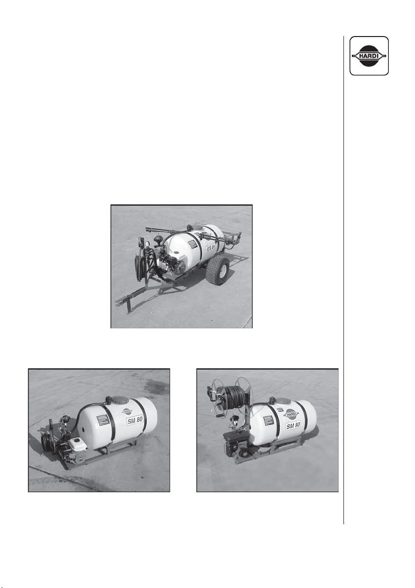
ES 80 with 14‘ HD Boom
SM 80 with Spraygun
and Hose Wrap
HARDI® GAS ENGINE ESTATE SPRAYER OPERATOR’S MANUAL
SM 80 with Spraygun
and Hose Reel
5
Page 8
2.0 SAFETY INFORMATION
WARNING!
ALWAYS READ THE OPERATOR’S MANUAL BEFORE
USING THIS EQUIPMENT
DO NOT REMOVE ANY SAFETY DEVICES OR
SHIELDS. NEVER SERVICE, CLEAN OR REPAIR A
MACHINE WHILE IT IS OPERATING
WARNING!
ALWAYS WATCH FOR THIS SYMBOL TO POINT OUT
IMPORTANT SAFETY PRECAUTIONS
IT MEANS ATTENTION! BECOME ALERT!
YOUR SAFETY IS INVOLVED!
6
HARDI® GAS ENGINE ESTATE SPRAYER OPERATOR’S MANUAL
Page 9

RECOGNIZE SAFETY INFORMATION
This is the Safety-alert symbol. When you see this
symbol on your machine or in this manual, be alert
to the potential for personal injury.
Follow recommended precautions and safe operating practices.
2.1 Follow Safety Instructions
1. Carefully read all the safety messages in this manual and the
safety labels fitted to the machine. Keep safety labels in good
condition. Replace missing or damaged safety labels. Make sure
that new equipment components include any current safety labels.
Replacement safety labels are available from your authorized
HARDI® dealer.
2. Learn how to operate the sprayer and how to use the controls
properly. Do not let anyone operate the sprayer without proper
instructions.
3. Keep your sprayer in proper working condition. Unauthorized
modifications or use may impair the function and/or safety and
affect the machine’s life.
4. If you do not understand any part of this manual and need assistance, please contact your authorized HARDI® dealer.
2.2 Operating The Sprayer Safely
1. Read the complete manual carefully and become familiar with the
operation of the equipment before initial operation in each spraying season. Failure to do so may result in possible over or under
application of spray solution and may lead to personal injury.
2. Always keep children away from your estate sprayer.
3. Never pull your estate sprayer behind a truck on public roads.
Load the sprayer onto a trailer or into the back of a truck for
transporting.
4. Understand service procedures before undertaking any maintenance. Never lubricate, service, or adjust the machine while it’s
moving. Securely support any components before working on
them.
5. Keep all parts in good condition and properly installed. Repair
damaged parts immediately. Replace worn or broken parts.
HARDI® GAS ENGINE ESTATE SPRAYER OPERATOR’S MANUAL
7
Page 10

2.3 Handling Chemical Products Safely
1. Direct exposure to hazardous chemicals can cause serious injury.
These chemicals can include lubricants, coolants, paints, adhesives and agricultural chemicals. Material Safety Data Sheets
(M.S.D.S.) are available for all hazardous chemicals which inform
the user of specific details including, physical and health hazards,
safety procedures, and emergency response techniques.
2. Protective clothing such as rubber gloves, goggles, coveralls and
respirator must be worn while handling chemicals. All protective
clothing should be kept in excellent condition and cleaned regularly or discarded.
3. If chemicals come in contact with any exposed skin areas, wash
immediately with clean water and detergent. Never place nozzle
tips or any other components that have been exposed to chemicals to lips to blow out obstructions. Use a soft brush to clean
spray nozzles.
4. Dedicate an area to fill, flush, calibrate and decontaminate sprayer
where chemicals will not drift or run off to contaminate people,
animals, vegetation, water supply, etc. Locate this area where
there is no chance of children coming in contact with this residue.
5. Decontaminate equipment used in mixing, transferring and
applying chemicals after use. Follow the instructions on the
chemical label for the correct procedure required. Wash spray
residue from outside of the sprayer to prevent corrosion.
6. Extreme care should be taken in measuring spray products.
Powders should be used in suitable sized packages or weighed
accurately. Liquids should be poured into a suitable graduated
container. Keep chemical containers low when pouring. Wear a
filtered respirator and let the wind blow away from you to avoid
dust and/or splashes contacting the skin or hair.
7. Store chemicals in a separate, plainly marked locked building.
Keep the chemical in its original container with the label intact.
8. Dispose all empty containers after rinsing in accordance with local
regulations & by-laws. Dispose of all unused chemicals and left
over fertilizer in an approved manner
9. Keep a first aid kit and fire extinguisher available at all times when
handling chemicals.
8
HARDI® GAS ENGINE ESTATE SPRAYER OPERATOR’S MANUAL
Page 11

2.4 Local Poison Information Center
PHONE NO. _________ - _________ - _____________
Find the phone number for the poison control center in your phone book
and write it in the space above.
Keep a list, in the space provided below, of all the chemicals that you have
in use.
1. ___________________________________________________
2. ___________________________________________________
3. ___________________________________________________
4. ___________________________________________________
5. ___________________________________________________
6. ___________________________________________________
7. ___________________________________________________
8. ___________________________________________________
9. ___________________________________________________
10. ___________________________________________________
HARDI® GAS ENGINE ESTATE SPRAYER OPERATOR’S MANUAL
9
Page 12
3.0 HOOKING UP THE SPRAYER
TOW VEHICLE REQUIREMENTS:
Lawn & Garden tractor or ATV with a drawbar with sufficient horsepower and braking ability to safely control the following specifications:
Sprayer
ES 50
ES 80
1. ES 50 and ES 80: Attach sprayer tongue to drawbar with the
correct size drawbar pin and install safety clip.
SM 50 and SM 80: Secure sprayer to bed of truck/utility vehicle.
WARNING:
MAKE SURE THAT YOUR SKID MOUNT SPRAYER IS
634
940
Tongue Weight (lbs.)Total Loaded Weight (lbs.)
92
66
PROPERLY SECURED AND THAT YOUR TRUCK/UTILITY
VEHICLE HAS SUFFICIENT CARRYING CAPACITY FOR YOUR
SPRAYER PLUS THE WEIGHT OF THE SPRAY LIQUID.
IMPORTANT:
Sprayer
SM 50
SM 80
The HARDI® Estate sprayers equipped with gas en-
Total Loaded Weight (lbs.)
616
852
gines are shipped from the factory without oil in the engine crankcase
or reduction gearbox.
2. Before operating the gas engine, you must:
A. Check the engine crankcase oil level.
B. Check the reduction gearbox oil level.
C. Fill the gas tank.
D. Make sure engine air filter is not plugged.
3. Refer to gas engine operating manual for oil change and maintenance information.
4. Tire pressure should be 10 PSI (ES 50, ES 80 only).
10
HARDI® GAS ENGINE ESTATE SPRAYER OPERATOR’S MANUAL
Page 13
4.0 OPERATING THE SPRAYER
WARNING:
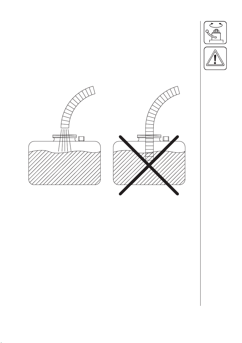
WATER ONLY. ALWAYS FILL WATER THROUGH THE STRAINER
BASKET TO PREVENT FOREIGN PARTICLES FROM ENTERING
THE TANK. NEVER LET THE FILLING HOSE ENTER THE TANK.
CHEMICALS MAY CONTAMINATE THE WATER SUPPLY LINES,
PLANT AND/OR WELL.
ALWAYS FILL YOUR ESTATE SPRAYER WITH CLEAN
4.1 CONTROLS
The ES and SM series estate sprayers use different controls for
operating. The ES 50 and ES 80 sprayers use the ET manual control
(Section 4.2), while the SM 50 and SM 80 use the M600 brass manual
control (Section 4.3).
HARDI® GAS ENGINE ESTATE SPRAYER OPERATOR’S MANUAL
11
Page 14
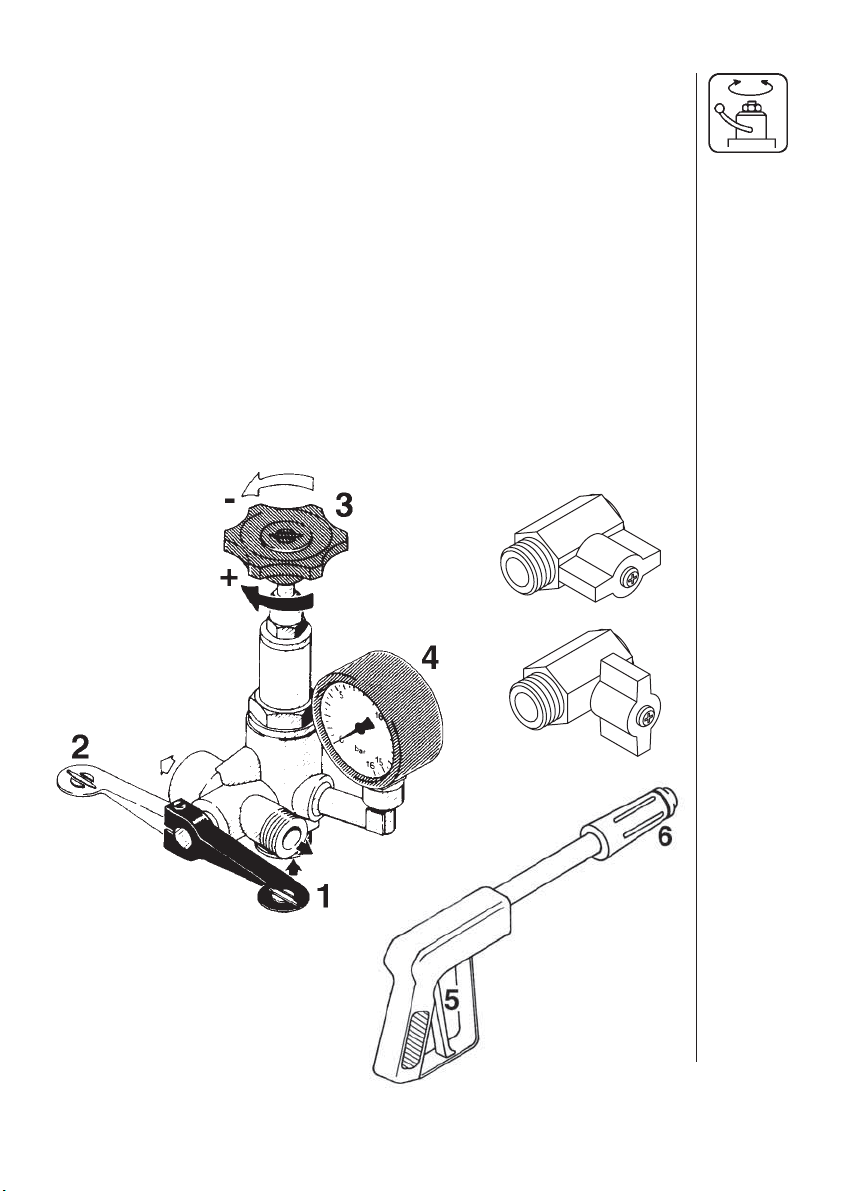
4.2 ET MANUAL CONTROL OPERATION (ES 50/80)
C
D
TANK
E
F
A. 500/600 Pump
B. Distribution Valves
C. Spraygun
D. Boom
E. Safety Valve
F. Agitation
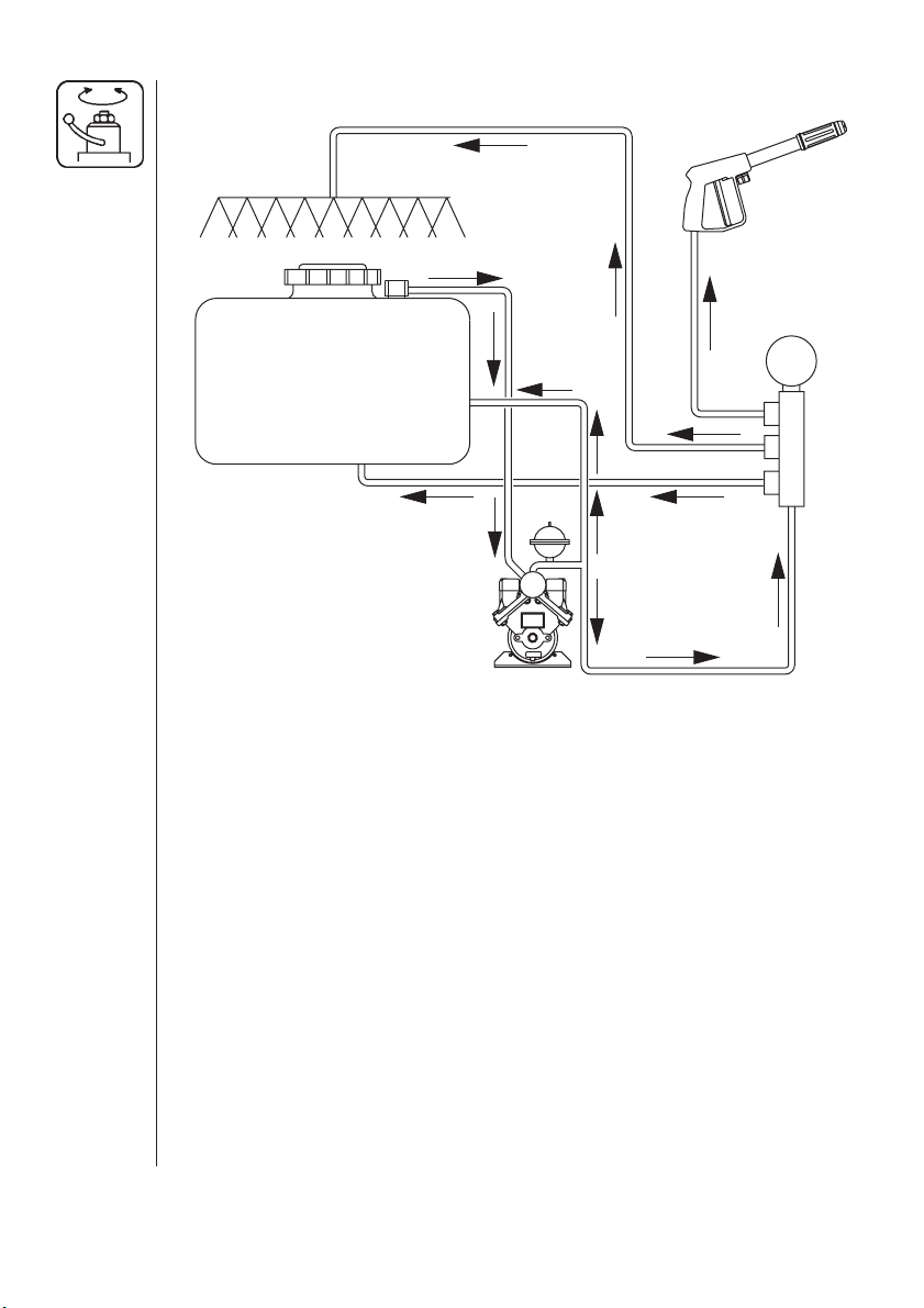
Fluid System Overview
When the 500/600 pump A (Fig 1) is running, pressurized fluid flows
from the tank to the distribution valves B (Fig 1). Fluid that is not
required for use by the boom or spraygun is returned to the tank
through the bypass line and agitation nozzle F (Fig 1). When the boom
valve is open, fluid flows to the boom D (Fig 1). When the spraygun
valve is open and the red handle on the spraygun is depressed, fluid
flows to the spraygun C (Fig 1). If the boom and spraygun valves are
off and the pressure valve is set too low to handle the output from the
pump, the safety valve E (Fig 1) opens to allow the fluid to return to the
tank.
Fig. 1
A
B
12
Boom Operation
1. Locate your sprayer in a suitable location to spray water from the
boom and/or handgun.
2. Fill the tank with clean water.
3. Turn dial 1 (Fig. 2) counter clockwise all the way out.
4. Set boom switch 2 (Fig. 2) on and spraygun switch 3 (Fig. 2) off.
5. Start the engine.
HARDI® GAS ENGINE ESTATE SPRAYER OPERATOR’S MANUAL
Page 15
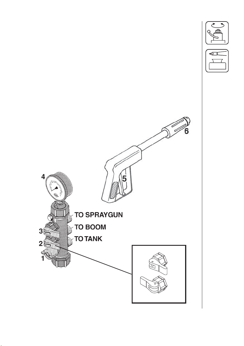
6. Increase pressure by turning dial 1 (Fig. 2) clockwise. Watch the
pressure gauge 4 (Fig. 2) until the desired pressure is reached
(turning dial 1 (Fig. 2) counter clockwise decreases pressure).
NOTE: Refer to Section 5.0 for nozzle selection and calibration.
Spraygun Operation
7. To operate the spraygun, turn switch 2 (Fig. 2) off and switch 3
(Fig. 2) on. Then depress the red handle 5 (Fig. 2) to spray water
from the spraygun. Check the pressure on gauge 4 (Fig. 2) and
follow step 6 to adjust.
8.
To adjust the spray pattern, turn the black handle 6 (Fig. 2)
OUT for
a narrow spray pattern for long distances and IN for a wide pattern
for more coverage at close distances.
ON
Fig. 2
HARDI® GAS ENGINE ESTATE SPRAYER OPERATOR’S MANUAL
OFF
13
Page 16
4.3 M600 BRASS MANUAL CONTROL OPERATION (SM 50/80)
C
F*
TANK
B
E*
D
Fig. 3
A. 500/600 Pump
B. M600 Control
C. Spraygun
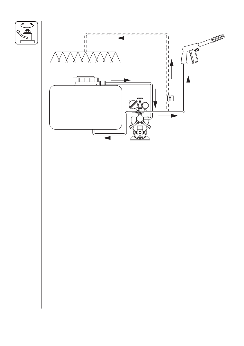
Fluid System Overview
When the 500/600 pump A (Fig 3) is running, pressurized fluid flows
from the tank to the M600 brass manual control B (Fig 3). When the
main ON/OFF valve is “OFF”, fluid is returned to the tank through the
bypass line and agitation nozzle D (Fig 3). When the main ON/OFF
valve is “ON” and the red handle on the spraygun is depressed, fluid
flows to the spraygun C (Fig 3). Optional boom: when main ON/OFF
valve is “ON” and boom valve E* (Fig 4) is open, fluid flows to the
boom F* (Fig 3).
Spraygun/(Optional Boom) Operation
1. Locate your sprayer in a suitable location to spray water from the
spraygun (and/or optional boom).
2. Fill the tank with clean water.
3. Turn main ON/OFF handle to spraying position 1 (Fig 4).
4. Turn dial 3 (Fig 4) counter clockwise all the way out. This relieves
the pressure on the springs and minimizes start-up problems.
(If optional boom is installed, make sure boom valve 7 (Fig 4) is
closed).
5. Start the engine.
D. Agitation - (Control Valve Bypass)
E*. Boom Valve (Optional)
F*. Boom (Optional)
A
14
HARDI® GAS ENGINE ESTATE SPRAYER OPERATOR’S MANUAL
Page 17
6. Increase pressure by turning dial 3 (Fig 4) clockwise. Watch the
pressure gauge 4 (Fig. 4) until the desired pressure is reached
(turning dial 3 (Fig 4) counter clockwise decreases pressure).
7. To operate the spraygun, depress the red handle 5 (Fig 4) to spray
water from the spraygun. Check the pressure on gauge 4 (Fig 4)
and follow step 6 to adjust.
8.
To adjust the spray pattern, turn the black handle 6 (Fig 4)
a narrow spray pattern for long distances and IN for a wide pattern
for more coverage at close distances.
9. To stop liquid flow to the spraygun (and optional boom), turn main
ON/OFF handle to position 2 (Fig 4). The entire fluid flow from the
pump will then return to the tank through the by-pass line.
10. To operate optional boom, turn main ON/OFF handle to spraying
position 1 (Fig 4) and open boom valve 7 (Fig 4) to spray water
from the boom. Check the pressure on gauge 4 (Fig 4) and follow
step 6 to adjust.
OUT for
OPEN
7
CLOSED
Fig. 4
HARDI® GAS ENGINE ESTATE SPRAYER OPERATOR’S MANUAL
15
Page 18

5.0 NOZZLE SELECTION
As standard equipment with your estate sprayer, nozzles have been
provided for both the handgun and boom.
5.1 Handgun Nozzle Selection
The 1099-20 nozzle (HARDI® ref. no. 371314) is the standard nozzle
for the handgun. This nozzle supplies the following rates in U.S.
gallons per minute at the given pressures:
GPM
NOZZLE
1099-20
PSI
20
30
40
50
60
70
100
150
200
0.678
0.829
0.956
1.068
1.169
1.261
1.504
1.840
2.123
0.538
0.661
0.766
0.857
0.940
1.018
1.222
1.500
1.736
Other size 1099 nozzles are available from you HARDI® Dealer.
5.2 Boom Nozzle Selection
ISO F-03-110 BLUE nozzles (HARDI® ref. no. 371767) are standard
on the 6’ boom and 14’ boom for gas engine driven systems. If you
find by using the following directions and nozzle chart, that these
nozzles are not the correct size for your spraying needs, other nozzles
are available from your HARDI® Dealer.
NOTE: A Calibration & Nozzles Manual (HARDI® ref. no. 67000103) is
available from your HARDI® dealer which contains more detailed
information for calibration and nozzle selection.
TO USE THE FOLLOWING CHART:
16
1. You must know your desired forward speed (example 3 MPH).
2. You must know the pressure (PSI) you want to spray at (example
30 PSI).
3. You must know your desired application rate (example 16 gallons
per acre).
HARDI® GAS ENGINE ESTATE SPRAYER OPERATOR’S MANUAL
Page 19
KNOWING THESE THREE FACTS, PROCEED AS FOLLOWS:
1. Locate the correct speed column on the chart below (example 3
M.P.H.).
2. Find the number in that column which is closest to your desired
application rate and is also opposite the desired pressure (example
16.8 GPA is closest to 16 GPA and opposite 30 PSI).
3. For this example, you would select the F-02-110 YELLOW nozzle.
NOTE: Using this chart will bring you very close to your desired application rate. However, for final pressure setting, you must calibrate your
sprayer (Section 6.0).
HARDI® ISO F-110 SPRAY SYNTAL NOZZLES
GPA at MPH
NOZZLE PSI 3
GPM 6
20 0.071
ISO
F-01-110
ORANGE
(371764)
30
40
50
60
0.087
0.100
0.113
0.122
2
10.5
12.9
14.8
16.8
18.1
MPH
MPH
7.0
8.6
9.9
11.2
12.1
4
MPH
5.3
6.5
7.4
8.4
9.1
5
MPH
4.2
5.2
5.9
6.7
7.2
MPH
3.5
4.3
5.0
5.6
6.0
20 0.11
ISO
F-015-110
GREEN
(371765)
ISO
F-02-110
YELLOW
(371766)
ISO
F-03-110
BLUE
(371767)
HARDI® GAS ENGINE ESTATE SPRAYER OPERATOR’S MANUAL
30
40
50
60
20
30
40
50
60
20
30
40
50
60
0.13
0.15
0.17
0.18
0.14
0.17
0.20
0.23
0.24
0.21
0.26
0.30
0.34
0.37
16.3
19.3
22.2
25.2
26.7
20.8
25.2
29.7
34.1
35.6
31.1
38.6
44.6
50.5
54.9
10.9
12.9
14.8
16.8
17.8
13.9
16.8
19.8
22.8
23.8
20.8
25.7
29.7
33.7
36.6
8.2
9.7
11.1
12.6
13.3
10.4
12.6
14.8
17.1
17.8
15.6
19.3
22.3
25.2
27.5
6.5
7.7
8.9
10.1
10.7
8.3
10.1
11.9
13.7
14.3
12.5
15.4
17.8
20.2
22.0
5.4
6.4
7.4
8.4
8.9
6.9
8.4
9.9
11.4
11.9
10.4
12.9
14.8
16.8
18.3
17
Page 20

6.0 CALIBRATION
WARNING:
WATER ONLY! WEAR PROTECTIVE CLOTHING SUCH AS RUBBER GLOVES, GOGGLES AND COVERALLS.
Why must you calibrate a sprayer?
A nozzle selection chart will tell you what application rate you should
expect. Variations due to nozzle wear, errors in pressure adjustment,
and tractor speedometer can result in a large error in application rate.
How do you calibrate a sprayer?
Calibration kits are available from HARDI®, #818493 for U.S. Gallons
and #818492 for metric calibration. For accurate calibration, the
sprayer is driven a specific distance at spraying speed and the length
of time is recorded. The operator then measures the amount of water
sprayed from one nozzle at spraying pressure for the same length of
time noted. The amount of water sprayed provides a direct reading of
application rate. Slight adjustments are then made by varying the
pressure.
Here are some tips to remember when using the calibration kit method:
1. Calibrate with clean water only.
2. Follow the instructions in the calibration kit carefully.
3. Before calibration, check the flow of each nozzle. If it puts out more
than 10% of its original volume, replace it.
4. When determining the length of time required to drive a recommended distance, drive in actual field or lawn conditions with a half full
sprayer. Repeat the test several times, then take the average of the
times recorded.
5. Calibration of the sprayer should be completed at the beginning of
the season and repeated every 2 to 3 full days of spraying, and every
time you change volume rate or use different nozzles.
ALWAYS CALIBRATE YOUR SPRAYER WITH CLEAN
18
NOTE: A Calibration & Nozzles Manual (HARDI® ref. no. 67000103) is
available from your HARDI® dealer which contains more detailed
information for calibration and nozzle selection.
HARDI® GAS ENGINE ESTATE SPRAYER OPERATOR’S MANUAL
Page 21

6.1 Calibration (Ounce Method)
If you do not wish to use the calibration kit method, the following
method may be used. All you need is a tape measure, stop watch and
a container that accurately measures U.S. fluid ounces.
1. Fill the sprayer tank approximately half full with clean water.
2. Set up two stakes, 204 ft. apart in actual spraying conditions.
3. While driving at spraying speed, note the length of time required to
drive 204 ft. Repeat several times and take the average of the times
recorded.
4. With the sprayer operating at intended spraying pressure, collect the
output from one nozzle for the length of time determined in step 3.
The number of U.S. fluid ounces will exactly measure the application
rate.
e.g. 15 U.S. fluid ounces = 15 U.S. gallons per acre
NOTE: This method only works if the nozzle spacing is 20”.
For conversion to Imperial gallons per acre, multiply U.S. GPA x .833
For conversion to liters per hectare, multiply U.S. GPA x 9.34
For conversion to liters per acre, multiply U.S. GPA x 3.78
7.0 MAINTENANCE
WARNING:
PEOPLE AND ANIMALS. NEVER LEAVE A SPRAYER CONTAINING CHEMICALS WHERE IT COULD BE ACCESSED BY UNAUTHORIZED PEOPLE OR ANIMALS.
IMPORTANT:
before servicing to avoid unnecessary contact with chemicals.
In order to derive full benefit from the sprayer for many years, the
following few, but important rules should be followed.
7.1 Cleaning The Sprayer
Read the entire label of the chemical used. Take note of any particular
instructions regarding recommended protective clothing, deactivating
agents, etc. Read the detergent and deactivating agent labels. If
cleaning procedures are given, follow them closely.
UNCLEAN SPRAYERS CAN BE HAZARDOUS TO
Always clean the boom at the end of your workday or
HARDI® GAS ENGINE ESTATE SPRAYER OPERATOR’S MANUAL
19
Page 22

7.1 Cleaning The Sprayer (cont.)
Be familiar with local legislation regarding disposal of agricultural
chemicals, mandatory decontamination methods, etc. Contact the
appropriate office, e.g. Department of Agriculture.
Cleaning starts with calibration as a well calibrated sprayer will ensure
the minimal amount of remaining spray liquid. It is a good practice to
clean the sprayer immediately after use thereby rendering the sprayer
safe and ready for the next application. This also prolongs the life of
the components.
It is sometimes necessary to leave the spray liquid in the tank for short
periods of time (e.g. overnight), or until the weather becomes suitable
for spraying again. Unauthorized persons and animals must not have
access to the sprayer under these circumstances.
Cleaning
1. Dilute the remaining spray liquid in the tank with at least 10 parts
water and spray the liquid out into the field or lawn you have just
sprayed.
2. Select and use the appropriate protective clothing. Select detergent
suitable for cleaning and suitable deactivation agents if necessary.
3. Rinse and clean sprayer and tractor externally. Use detergent if
necessary.
4. Remove all filters and clean them. Be careful not to damage the
mesh. Replace filters when the sprayer is completely clean.
5. With the pump running, rinse the inside of the tank. Remember the
tank roof. Rinse and operate all components and any equipment that
has been in contact with the chemical.
6. After spraying the liquid out again in the field or lawn, stop the pump
and fill at least 1/5 of the tank with clean water. Note that some
chemicals require the tank to be completely filled. Add appropriate
detergent and/or deactivating agent, e.g. Washing soda or Triple
ammonia.
20
NOTE: If a cleaning procedure is given on the chemical label, follow it
closely.
7. Start the pump and operate all controls enabling the liquid to come
in contact with all the components. Leave the distribution valves until
last. Some detergents and deactivating agents work best if left in the
tank for a short period. Check the label.
HARDI® GAS ENGINE ESTATE SPRAYER OPERATOR’S MANUAL
Page 23

8. Drain the tank and let the pump run dry. Rinse inside of tank, again
letting the pump run dry.
9. Stop the pump. If the chemicals used have a tendency to block
nozzles, remove and clean them now.
10. Replace all filters and nozzles and store the sprayer. If, from
previous experiences, it is noted that the solvents in the chemicals
are particularly aggressive, store the sprayer with the tank lid open.
NOTE: If the sprayer is cleaned with a high pressure cleaner, we
recommend lubrication of the entire machine.
7.2 Lubrication
Every 40 hours of operation, new grease should be applied to the
pump and boom. Use a high quality multi-purpose lithium based
grease. When greasing the pump, use only 2 to 3 pumps from a
grease gun. For easier application of grease to the boom, place the
wing in the breakaway position. Also oil the M600 control as shown
every 40 hours of operation.
WARNING:
NEVER PLACE FINGERS IN BREAKAWAY CLUTCH.
TO PREVENT SERIOUS INJURY FROM CRUSHING,
14‘ HD Boom
Grease
Grease
Pump
Grease
M600
Control
6‘ FD Boom
HARDI® GAS ENGINE ESTATE SPRAYER OPERATOR’S MANUAL
21
Page 24

7.3 Nozzle Filters
WARNING:
WITHOUT WEARING CHEMICAL RESISTANT GLOVES AND
SAFETY GOGGLES.
Each nozzle assembly is equipped with a 50 mesh filter screen as
standard. A properly maintained suction filter will eliminate plugging of
the screens and nozzles.
NEVER SERVICE YOUR CONTAMINATED NOZZLES
7.4 Nozzle Tubes and Fittings
Poor seals are usually caused by:
• Missing O-rings or gaskets
• Damaged or incorrectly seated O-rings
• Dry or deformed O-rings or gaskets
• Foreign materials
Therefore, in case of leaks; DO NOT overtighten any fittings (Fig 5).
Disassemble, check the condition and position of the O-ring or gasket,
clean, lubricate and then reassemble. For radial seals (O-ring) (Fig 5),
only hand tighten the fittings. Do not use pliers or wrenches.
The O-rings need to be lubricated ALL THE WAY AROUND before
fitting on to the nozzle.
22
Fig. 5
HARDI® recommends using a vegetable based oil to prolong the life of
the O-ring.
7.5 Pump Maintenance
Changing the valves
Remove valve cover 1 (Fig 6). Before changing the valves 2 (Fig 6),
note the orientation of the valves so that they may be replaced
correctly. It is recommended to use new seals 3 (Fig 6) when changing
or checking the valves.
HARDI® GAS ENGINE ESTATE SPRAYER OPERATOR’S MANUAL
Page 25

Changing the diaphragms
Remove the diaphragm cover 4 (Fig 6) after removing the valve cover.
The diaphragm 5 (Fig 6) may then be changed. If fluids have reached
the crankcase, re-grease the pump thoroughly. Also make sure the
drain hole at the bottom of the pump is not blocked. Use the following
torque chart when re-tightening bolts:
Diaphragm Bolt - 18.5 Ft/Lbs
Diaphragm Cover Bolts - 37 Ft/Lbs
Valve Cover Bolts (500) - 22 Ft/Lbs
Valve Cover Bolts (600) - 34 Ft/Lbs
Fig. 6
Model 600
7.6 Boom Maintenance
The 6’ FD boom breakaway should be
adjusted tightly enough so that the boom
stays securely in the upright (folded)
position during transport, yet loosely
enough that the boom easily swings back
if an obstacle is hit. Adjustment is made
by tightening or loosening the spring
tension bolt (Fig 7).
HARDI® GAS ENGINE ESTATE SPRAYER OPERATOR’S MANUAL
Model 500
Spring Tension
Bolt
Fig. 7
23
Page 26

8.0 STORAGE
When the spraying season is over, you should devote some extra time
to the sprayer. If chemical residues are left over in the sprayer for long
periods, it can reduce the life of the individual components. To
preserve the sprayer and protect the components, carry out the
following off-season storage program:
1. Clean the sprayer completely - inside and outside - as described in
Section 7.1 “Cleaning The Sprayer“. Make sure that all valves,
hoses and auxiliary equipment have been cleaned with detergent
and flushed with clean water afterwards, so no chemical residues
are left in the sprayer.
2. Replace any damaged seals and repair any leaks.
3. Empty the sprayer completely and let the pump work for a few
minutes. Operate all valves and handles to drain as much water out
of the spraying circuit as possible. Let the pump run until air is
coming out of all nozzles.
4. Fill the tank with 3 - 5 gallons of an ethylene glycol base anti-freeze
mixture at the ratio for the desired temperature protection. Run the
pump and circulate the anti-freeze through the distribution valves
and boom lines. Spray the handgun into the tank until anti-freeze
sprays out to make sure the line is full of anti-freeze.
NOTE: Never use diesel fuel in a sprayer.
5. When the sprayer is dry, remove rust from any scratches in the paint
and touch up the paint.
6. Lubricate the boom (Section 7.2).
7. Remove the glycerine-filled pressure gauge and store in a vertical
position in a frost-free environment.
8. To protect against dust, the sprayer can be covered by a tarpaulin.
Ensure ventilation to prevent condensation.
24
8.1 Preparation After Storage
After a storage period, the sprayer should be prepared for the next
season in the following way:
1. Remove the cover (If fitted).
2. Fit the pressure gauge again. Seal with Teflon tape.
3. Connect the sprayer to the tow vehicle (Section 3.0).
4. Empty the remaining antifreeze into an approved container.
5. Rinse the entire liquid circuit on the sprayer with clean water. Don’t
forget to flush the boom and handgun lines also.
6. Fill with clean water and check all functions (Section 4.0).
HARDI® GAS ENGINE ESTATE SPRAYER OPERATOR’S MANUAL
Page 27

9.0 TROUBLESHOOTING
Problem
1. Lack of Pressure
2. Pressure jumping
Solution
A. Check that suction filter is
not clogged.
B. Check suction line from tank
to pump for leaks.
C. Check that pressure regula-
tor seat is not damaged.
D. Check pump valves for
obstructions and wear.
Replace valves if necessary.
(Section 7.5)
E. Check pressure gauge.
A. Check that suction filter is
not partially clogged.
B. Check that pressure regula-
tor is functioning properly.
C. Check that non-drip nozzle
diaphragms are functioning
correctly (should open at 10
PSI).
D. Check safety valve for weak
or broken valve spring.
E. Check pressure gauge.
3. Liquid leaks from
bottom of pump
4. No spray from
spraygun or boom
HARDI® GAS ENGINE ESTATE SPRAYER OPERATOR’S MANUAL
A. Replace diaphragm(s).
(Section 7.5)
A. Check suction tube and
fittings.
B. Check suction line from tank
to pump for leaks.
C. Check tightness of pump
diaphragm and valve covers.
(Section 7.5)
25
Page 28

9.0 TROUBLESHOOTING (cont.)
Problem
5. Inadequate weed control
A. Re-calibrate sprayer.
B. Check chemical container
instructions.
C. Did weather conditions affect
application?
D. Take care when driving not to
overlap or miss spraying.
E. Did you stop vehicle in field or
lawn and leave sprayer running?
Solution
10.0 TECHNICAL SPECIFICATIONS
10.1 HARDI® Diaphragm Pump Specifications
PUMP MODEL
Number of Diaphragms
Maximum Pressure
Maximum Flow @540 RPM
4.2 GPM (16 l/min)
500
1
220 PSI (15 Bar)
220 PSI (15 Bar)
8.2 GPM (31 l/min)
600
2
26
HARDI® GAS ENGINE ESTATE SPRAYER OPERATOR’S MANUAL
Page 29

10.2 Sprayer Specifications
Sprayer
Type
ES 50
ES 80
SM 50
SM 80
*
Optional
Tank
Capacity
(Gallons)
50
80
50 (14')
80 (14')
10.3 Safety Decals
Red Reflector Decal - 10533803
Amber Reflector Decal - 10533903
10533003
Boom
Type
(Ft.)
6'
14'
6'
14'
Spray
Width
(Ft.)
6'7"
13'4"
6'7"
13'4"
*
(13'4")*57 x 28 x 49 194
*
(13'4")*68 x 24 x 51 210
Dimensions
L x W x H
(Inches)
85 x 42 x 39
99 x 45 x 40
10533103
Empty
Weight
(lbs.)
264
312
10533203
HARDI® GAS ENGINE ESTATE SPRAYER OPERATOR’S MANUAL
27
Page 30

11.0 PARTS DRAWINGS
500 PUMP
28
HARDI® GAS ENGINE ESTATE SPRAYER OPERATOR’S MANUAL
Page 31
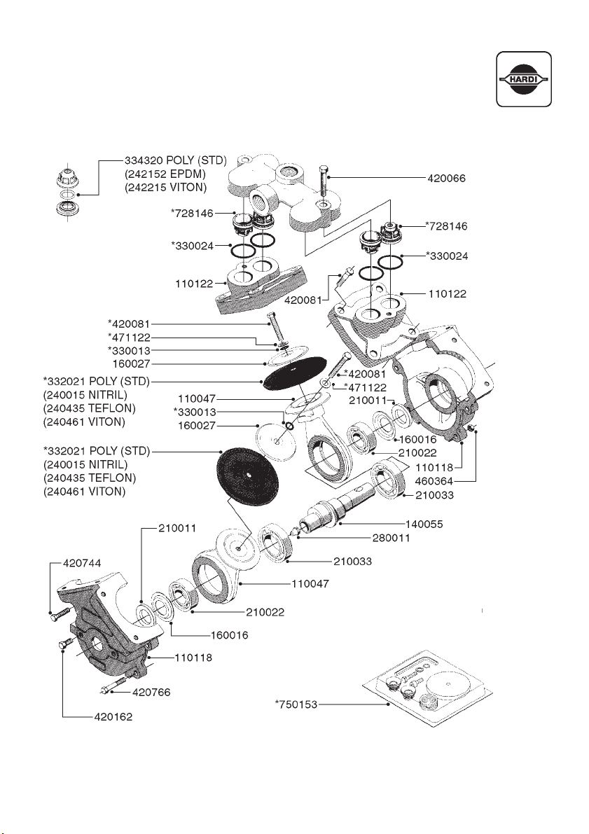
600 PUMP
HARDI® GAS ENGINE ESTATE SPRAYER OPERATOR’S MANUAL
29
Page 32

330757
PUMP & ENGINE
28007203 (Briggs & Stratton 3.5 HP)
28007303 (Honda 4.0 HP)
410347
821041 (500)
821074 (600)
160003
420781
421046
471126
330746
146591
192415
450897
460143
420604
471122
460423
460143
460423
471126
450052
460202
420943
471122
450897
146590
927021 (xFT.)
168846
470046
460143
28014003
28013803
28013903
420744
HONDA
BRIGGS &
STRATTON
30
28008003
HARDI® GAS ENGINE ESTATE SPRAYER OPERATOR’S MANUAL
Page 33

PUMP FITTINGS
HARDI® GAS ENGINE ESTATE SPRAYER OPERATOR’S MANUAL
31
Page 34

ET MANUAL CONTROL
32
HARDI® GAS ENGINE ESTATE SPRAYER OPERATOR’S MANUAL
Page 35

M600 BRASS MANUAL CONTROL
HARDI® GAS ENGINE ESTATE SPRAYER OPERATOR’S MANUAL
33
Page 36

ES 50/80 TANK
34
HARDI® GAS ENGINE ESTATE SPRAYER OPERATOR’S MANUAL
Page 37

ES 50/80 FRAME
HARDI® GAS ENGINE ESTATE SPRAYER OPERATOR’S MANUAL
35
Page 38

SM 50/80 TANK & FRAME
36
HARDI® GAS ENGINE ESTATE SPRAYER OPERATOR’S MANUAL
Page 39

440086
6‘ FD BOOM
460261
440086
410362
240074
322260
725043
371767
(ISO F-03-110 BLUE)
330212
320047
716166
440086
333465
725726 RH
725727 LH
333465
460261
334581
321462
333012
334533
927284 (x FT.)
430874
470282
170775
320482
320386
330013
330783
320187
334533
220749
470282
330212
330676
927284 (x FT.)
334533
TO LEFT SIDE
614704
460703
320084
460423
420604
100305
927284 (x FT.)
927284 (x FT.)
TO CONTROL
HARDI® GAS ENGINE ESTATE SPRAYER OPERATOR’S MANUAL
37
Page 40

14‘ HD BOOM
38
HARDI® GAS ENGINE ESTATE SPRAYER OPERATOR’S MANUAL
Page 41

SPRAYGUN
HARDI® GAS ENGINE ESTATE SPRAYER OPERATOR’S MANUAL
39
Page 42
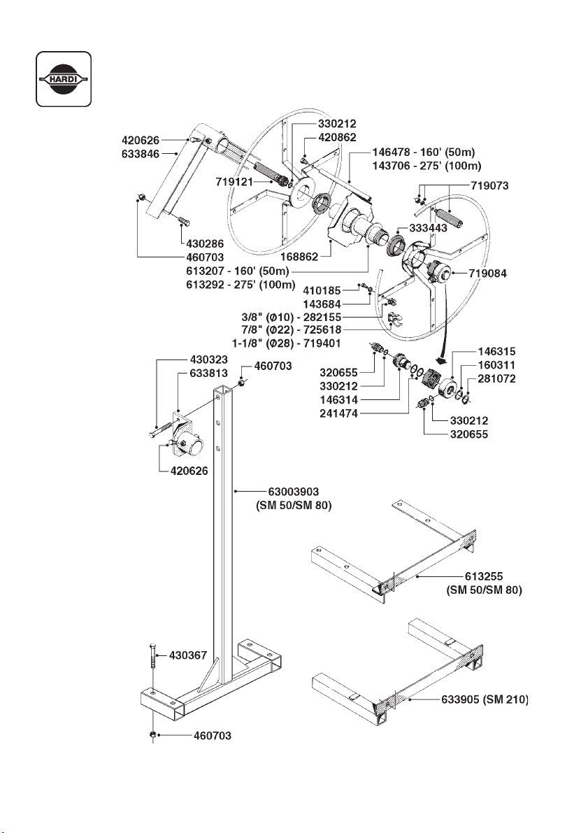
HOSE REEL
40
HARDI® GAS ENGINE ESTATE SPRAYER OPERATOR’S MANUAL
Page 43

12.0 WARRANTY POLICY AND CONDITIONS
HARDI® INC. , 1500 West 76th Street, Davenport, Iowa USA; 5646 W. Barstow, Fresno, California, USA; and
290 Sovereign Road, London, Ontario, Canada hereinafter called "HARDI
warranty in accordance with the provisions below to each original retail purchaser of HARDI
of its own manufacturer, from an authorized HARDI
such purchaser, free from defects in material and workmanship and that such equipment will be warranted for
a period of one year from the date of delivery to the end user providing the machine is used and serviced in
accordance with the recommendations in the Operator’s Manual and is operated under normal farm
conditions.
®
dealer, that such equipment is at the time of delivery to
®
", offers the following limited
®
new equipment
1. This limited warranty is subject to the following exceptions:
®
a) Parts of the machine not manufactured by HARDI
tires, tubes, electronic controls, and other components or trade accesories, etc.) are not covered by this warranty but are subject to the
warranty of the original manufacturer. Any claim falling into this category will be taken up with the manufacturer concerned.
b) This warranty will be withdrawn if any equipment has been used for
purposes other than for which it was intended or if it has been misused,
neglected, or damaged by accident, let out on hire or furnished by a
rental agency. Nor can claims be accepted if parts other than those
manufactured by HARDI
ment. Further, HARDI
or handling by any common carrier and under no circumstances within
or without the warranty period will HARDI
of use, or damages resulting from delay or any consequential damage.
2. We cannot be held responsible for loss of livestock, loss of crops, loss because of
delays in harvesting or any expense or loss incurred for labor, supplies, substitute
machinery, rental for any other reason, or for injuries either to the owner or to a
third party, nor can we be called upon to be responsible for labor charges, other
than originally agreed, incurred in the removal or replacement of components.
®
have been incorporated in any of our equip-
®
shall not be responsible for damage in transit
, (i.e. engines,
®
be liable for damages of loss
3. The customer will be responsible for and bear the costs of:
a) Normal maintenance such as greasing, maintenance of oil levels, minor
adjustments, etc.
b) Transportation of any HARDI
work is performed.
c) Dealer travel time to and from the machine or to deliver and return the machine
from the service workshop for repair.
®
product to and from where the warranty
d) Dealer traveling costs.
4. Parts defined as normal wearing items, (i.e. tires and V-belts) are not in any way covered
under this warranty.
5. This warranty will not apply to any product which is altered or modified without the express
written permission of HARDI
Dealer.
6. Warranty is dependent upon the strict observance by the purchaser of the following
provisions:
®
and/or repaired by anyone other than an Authorized Service
a) That this warranty may not be assigned or transferred to anyone.
b) That the Warranty Registration Certificate has been correctly completed by dealer
and purchaser with their names and addresses, dated, signed and returned to
the appropriate address as given on the Warranty Registration Certificate.
c) That all safety instructions in the operators manual shall be followed and all safety
guards regularly inspected and replaced where necessary.
HARDI® GAS ENGINE ESTATE SPRAYER OPERATOR’S MANUAL
41
Page 44

7. No warranty is given on second-hand products and none is to be implied.
8. HARDI
9. Subject to the following terms, conditions and contributions, HARDI® extends the warranty on
10. Subject to the following terms, conditions, contributions, HARDI
11. The judgement of HARDI
12. No employee or representative is authorized to change this warranty in any way or grant any
13. Any warranty work performed which will exceed $400.00
®
reserves the right to incorporate any change in design in its products without
obligation to make such changes on units previously manufactured.
polyethylene tanks (excluding fittings, lids and gaskets) to FIVE YEARS. To qualify for this
extended warranty, the tank must be drained and flushed with fresh water after each day of use.
®
’s liability is limited to replacement of the tank, FOB our plant at no cost to the purchaser
HARDI
during the first twelve months; at 20% of the then current price during the second year; at 40%
during the third year; at 60% during the fourth year; and at 80% during the fifth year. This five
year extended warranty is subject, in each instance, to the tank being inspected and approved
for replacement or repair by HARDI
hereunder.
®
HARDI
diaphragm pumps (excluding wearing parts such as diaphragms, valves, etc.) to FIVE
YEARS. To qualify for this extended warranty, the pump must be drained and flushed with fresh
water after each day of use. HARDI
our plants in Davenport, Iowa, USA and London, Ontario, Canada at no cost to the purchaser
during the first twelve months after date of purchase, at 20% of the then current retail price
during the second year; at 40% during the third year; at 60% during the fourth year; and at 80%
during the fifth year. This five year extended warranty is subject, in each instance, to the pump
being inspected and approved for replacement or repair by HARDI
will accept any liability hereunder.
conclusive and the purchaser agrees to accept its decisions on all questions as to defect and
to the exchange of any part or parts.
other warranty unless such change is made in writing and signed by an officer of HARDI
head office.
by the Service Manager.
®
personnel before HARDI® will accept any liability
®
extends the warranty on
®
’s liability is limited to replacement of defective parts, FOB
®
personnel before HARDI
®
in all cases of claims under this warranty shall be final and HARDI
®
MUST be approved IN ADVANCE
®
®
at its
14. Any pump replacement must be approved in advance by the Service Manager.
15. Claims under this policy must be filled with HARDI® within thirty (30) days of work performed or
warranty shall be void.
16. Parts requested must be returned prepaid within thirty (30) days for warranty settlement.
17. Warranty claims must be COMPLETELY filled out properly or will be returned.
DISCLAIMER OF FURTHER WARRANTY
THERE ARE NO WARRANTIES, EXPRESSED OR IMPLIED, EXCEPT AS SET FORTH ABOVE. THERE
ARE NO WARRANTIES WHICH EXTEND BEYOND THE DESCRIPTION OF THE PRODUCT CONTAINED
HEREIN. IN NO EVENT SHALL THE COMPANY BE LIABLE FOR INDIRECT, SPECIAL OR CONSEQUENTIAL DAMAGES (SUCH AS LOSS OF ANTICIPATED PROFITS) IN CONNECTION WITH THE RETAIL
PURCHASER'S USE OF THE PRODUCT.
42
HARDI® GAS ENGINE ESTATE SPRAYER OPERATOR’S MANUAL
Page 45

13.0 NOTES
HARDI® GAS ENGINE ESTATE SPRAYER OPERATOR’S MANUAL
43
Page 46

NOTES
44
HARDI® GAS ENGINE ESTATE SPRAYER OPERATOR’S MANUAL
Page 47

Page 48

For Product, Service or Warranty Information:
- Please contact your local HARDI® dealer.
To contact HARDI® directly:
- Please use the HARDI® Customer Service number: 1-866-770-7063
- Or send your email to: CUSTSERV@hardi-us.com
Visit us online at: www.hardi-us.com
HARDI® NORTH AMERICA INC.
1500 West 76th St.
Davenport, Iowa 52806
Phone: (563) 386-1730
Fax: (563) 386-1710
8550 W. Roosevelt Avenue
Visalia, California 93291
Phone: (559) 651-4016
Fax: (559) 651-4160
337 Sovereign Rd.
London, Ontario N6M 1A6
Phone: (519) 659-2771
Fax: (519) 659-2821
 Loading...