

Page 1

RANGER 2500
TR2
Original in french
Instruction manual
67788101-100 - Version 1.00
GB - 11.2013
www.hardi-international.com
Page 2

Thank you for choosing HARDI crop protection equipment. This product's
reliability and effectiveness depend on the care that you take with it. The first step
is to read this user manual carefully. It contains essential information that will
allow you to use and maintain this quality product effectively.
The original user manual was written and published in French. All other foreign language versions are translations
from the original. In the event of contradictions, inaccuracies or digressions between the original French version
and other foreign language versions, the French original will take precedence.
The illustrations, technical information and specifications provided in this manual are correct to our knowledge at
the time of printing. Since HARDI EVRARD SAS operates a policy of constant product improvement, we reserve
the right to modify the design, characteristics, components, specifications and maintenance instructions at any
time, without prior notice.
HARDI EVRARD does not accept any liability for equipment sold prior or subsequent to such modifications.
HARDI EVRARD has taken every care in writing this manual to ensure it is as complete and accurate as possible.
However, it cannot be held liable for any omissions or inaccuracies.
Since this manual covers a range of models, the characteristics or equipment described may differ from those
available in some countries. Take note only of the paragraphs that relate to your model.
Published and printed by HARDI EVRARD S.A.S.
Page 3

Sommaire
1 - EC declaration
EC Declaration of Conformity ................................................................................................................7
2- Safety instructions
3 - Description
General information ............................................................................................................................13
Using the sprayer ................................................................................................................................................................................................ 13
Driving on the road ............................................................................................................................................................................................ 13
Tank ............................................................................................................................................................................................................................. 13
Chassis ........................................................................................................................................................................................................................ 13
General view .......................................................................................................................................................................................................... 14
Identification plates ........................................................................................................................................................................................... 15
Spraying system ..................................................................................................................................16
Pump .......................................................................................................................................................................................................................... 16
Valves and pictograms ..................................................................................................................................................................................... 16
Regulation ............................................................................................................................................................................................................... 17
Diagrams - spraying system ......................................................................................................................................................................... 17
Filters ........................................................................................................................................................................................................................... 17
Cyclone Filter (optional) .................................................................................................................................................................................. 17
TurboFiller ................................................................................................................................................................................................................ 18
Boom ...................................................................................................................................................20
Boom and terminology ................................................................................................................................................................................... 20
Equipment ...........................................................................................................................................21
Hitch with hydraulic drawbar (optional) .............................................................................................................................................. 21
Step .............................................................................................................................................................................................................................. 21
Platform ..................................................................................................................................................................................................................... 21
Main tank gauge .................................................................................................................................................................................................. 22
Boom pressure gauge ...................................................................................................................................................................................... 22
Storage box (optional) ..................................................................................................................................................................................... 22
External cleaning equipment (optional) ............................................................................................................................................... 23
TR2 Y version control unit .............................................................................................................................................................................. 23
'Sprayll' spraying control ................................................................................................................................................................................ 24
'Hydraulic' control ............................................................................................................................................................................................... 24
4 - Sprayer set-up
General information ............................................................................................................................25
Precautions before use .................................................................................................................................................................................... 25
Unloading the sprayer ..................................................................................................................................................................................... 25
Lifting the sprayer with a jack ..................................................................................................................................................................... 25
Support leg ............................................................................................................................................................................................................. 26
Transmission shaft ..............................................................................................................................27
User safety ............................................................................................................................................................................................................... 27
Connecting the transmission shaft .......................................................................................................................................................... 27
Mechanical equipment ........................................................................................................................29
Hitches ....................................................................................................................................................................................................................... 29
Articulated hitch with tilt correction (optional) ............................................................................................................................... 29
Track width, axles and wheels .............................................................................................................30
Modifying the track width ............................................................................................................................................................................. 30
Tyre inflation pressures .................................................................................................................................................................................... 30
Brakes ..................................................................................................................................................31
Parking and safety brake ................................................................................................................................................................................. 31
Hydraulic braking ................................................................................................................................................................................................ 31
Hydraulic system .................................................................................................................................32
General information .......................................................................................................................................................................................... 32
Version TR2 Y hydraulic connection ........................................................................................................................................................ 32
Version TR2 V and TR2 Z hydraulic connection ................................................................................................................................ 32
Open centre hydraulic block (optional) ................................................................................................................................................ 33
Electrical connections ..........................................................................................................................34
3
Page 4

Sommaire
Installing the control unit supports ......................................................................................................................................................... 34
Electrical supply ................................................................................................................................................................................................... 34
Sprayer speed sensor ........................................................................................................................................................................................ 35
Road signalling ..................................................................................................................................................................................................... 35
Spraying system ..................................................................................................................................36
Use of electrical EVC adjustment .............................................................................................................................................................. 36
5 - Operation
Boom ...................................................................................................................................................37
Safety instructions .............................................................................................................................................................................................. 37
TR2 Y boom hydraulic controls .................................................................................................................................................................. 37
TR2 V and TR2 Z boom hydraulic controls .......................................................................................................................................... 39
Equipment ...........................................................................................................................................40
Articulated hitch with hydraulic tilt correction (optional) ......................................................................................................... 40
Driving technique with the articulated hitch .................................................................................................................................... 40
Spraying system ..................................................................................................................................41
General information .......................................................................................................................................................................................... 41
Filling/cleaning zone - Rules ........................................................................................................................................................................ 41
Filling the main tank .......................................................................................................................................................................................... 41
Filling via the opening in the tank ............................................................................................................................................................ 42
Filling the rinsing tank ...................................................................................................................................................................................... 42
Filling the hand wash tank ............................................................................................................................................................................ 43
Water filling device ............................................................................................................................................................................................ 43
Safety instructions - Agro-pharmaceutical products .................................................................................................................... 44
Parking the sprayer ............................................................................................................................................................................................ 44
Adding products through the opening in the tank ...................................................................................................................... 45
Adding liquid products via the TurboFiller ......................................................................................................................................... 45
Adding powder products via the TurboFiller .................................................................................................................................... 46
Cleaning the TurboFiller ................................................................................................................................................................................. 46
Agitation prior to resuming treatment .................................................................................................................................................. 47
Spray controls ........................................................................................................................................................................................................ 48
Quick guide - Operation ................................................................................................................................................................................. 48
Cleaning ...............................................................................................................................................49
General information .......................................................................................................................................................................................... 49
Quick guide - Cleaning .................................................................................................................................................................................... 50
Cleaning the tank and the spraying system ....................................................................................................................................... 50
Cleaning and maintaining the filters ...................................................................................................................................................... 51
Using the rinsing tank and the rotating nozzle. ............................................................................................................................... 51
Boom purge (optional) .................................................................................................................................................................................... 53
Dead volume ......................................................................................................................................................................................................... 53
Using the drain ..................................................................................................................................................................................................... 54
6 - Maintenance
Greasing ..............................................................................................................................................55
General information .......................................................................................................................................................................................... 55
Recommended lubricants ............................................................................................................................................................................. 55
Power take-off lubrication points and frequency ........................................................................................................................... 55
Boom lubrication points and frequency .............................................................................................................................................. 56
Chassis lubrication points and frequency ............................................................................................................................................ 56
Maintenance cycle ...............................................................................................................................57
Every 10 hours - Spraying system ............................................................................................................................................................. 57
Every 10 hours - Boom filters (optional) ................................................................................................................................................ 57
Every 10 hours - Cyclone filter ..................................................................................................................................................................... 58
Every 10 hours - Brakes (optional) ............................................................................................................................................................ 58
Every 50 hours - Transmission shaft ........................................................................................................................................................ 58
Every 50 hours - Tyre pressure .................................................................................................................................................................... 58
Every 250 hours - Wheel nuts and bolts ............................................................................................................................................... 58
Every 250 hours - Hydraulic system ......................................................................................................................................................... 59
Every 250 hours - Pipes and lines .............................................................................................................................................................. 59
4
Page 5

Sommaire
Every 250 hours - Hydraulic brakes (optional) ................................................................................................................................... 59
Every 250 hours - Parking brake check .................................................................................................................................................. 59
Every 250 hours - Wheel bearings ............................................................................................................................................................ 60
Every 1,000 hours - Wheel bearings (unbraked) .............................................................................................................................. 60
Every 1,000 hours - Hitch extension ........................................................................................................................................................ 61
Every 1,000 hours - Wheel bearings and brakes .............................................................................................................................. 61
Occasional maintenance ......................................................................................................................63
Checking/replacing the regulation valve piston ............................................................................................................................. 64
Checking/replacing valve gaskets on EVC valves ........................................................................................................................... 64
Adjusting the gauge ......................................................................................................................................................................................... 64
Replacing the steel cable on the gauge ............................................................................................................................................... 65
Replacing the drain valve gasket .............................................................................................................................................................. 65
Adjusting the 3-way valves ........................................................................................................................................................................... 65
Spray lines and connectors ........................................................................................................................................................................... 66
Replacing bulbs ................................................................................................................................................................................................... 66
Replacing the boom lights bulbs (optional) ...................................................................................................................................... 66
Replacing tyres ..................................................................................................................................................................................................... 67
Operating the safety valve ....................................................................................................
Adjusting the boom - general information ........................................................................................................................................ 69
Anti-yaw device ................................................................................................................................................................................................... 69
Central frame locking device ....................................................................................................................................................................... 69
Horizontally aligning the inner arms with the central frame ................................................................................................... 70
Adjusting the height of the boom on the transport supports ............................................................................................... 70
Adjusting the boom open/close ............................................................................................................................................................... 70
Winter storage .....................................................................................................................................71
Storage procedure ............................................................................................................................................................................................. 71
........................................................................ 68
7 - Fault finding
Operating incidents .............................................................................................................................73
General information .......................................................................................................................................................................................... 73
Spraying system ................................................................................................................................................................................................... 74
Hydraulic functions - Z boom ..................................................................................................................................................................... 75
Mechanical problems ..........................................................................................................................76
Backup operation - Spraying system ...................................................................................................................................................... 76
8 - Technical specifications
Dimensions ..........................................................................................................................................77
General information .......................................................................................................................................................................................... 77
Overall dimensions ............................................................................................................................................................................................ 77
Weight ....................................................................................................................................................................................................................... 77
Conversion factors, SI units into imperial ............................................................................................................................................. 77
Specifications ......................................................................................................................................................................................................... 78
Pump model 363/10.0 ..................................................................................................................................................................................... 78
Temperature and pressure ranges ........................................................................................................................................................... 78
Filters and nozzles .............................................................................................................................................................................................. 78
Reservoir specifications ................................................................................................................................................................................... 78
Tyre specifications .............................................................................................................................................................................................. 78
Raw materials and recycling ................................................................................................................79
Disposing of the sprayer ................................................................................................................................................................................. 79
Spraying system schematic diagrams .................................................................................................80
Basic spraying system ....................................................................................................................................................................................... 80
Spraying system with options ..................................................................................................................................................................... 81
Electrical connections ...................................................................................................................................................................................... 82
Road signalling ..................................................................................................................................................................................................... 82
Spray II unit electrical connections .......................................................................................................................................................... 82
EVC operating unit ............................................................................................................................................................................................. 83
TR2 Y version diagrams ................................................................................................................................................................................... 84
TR2 Y version diagrams ................................................................................................................................................................................... 85
5
Page 6

Sommaire
Index
Index ....................................................................................................................................................87
6
Page 7

EC Declaration of Conformity
The manufacturer:
Production unit
HARDI-EVRARD
301 rue du 21 mai 1940 - Beaurainville
France
1 - EC declaration
declares that the following equipment:
RANGER TR2 Y - RANGER TR2 V - RANGER TR2 Z
- Complies with all the relevant requirements in machinery directive 2009/127/EC, modifying directive 2006/42/EC.
- The requirements of Council Directive 2004/108/EC (EMC).
Beaurainville 01.06. 2013
Managing Director
HARDI EVRARD
7
Page 8

1 - EC declaration
8
Page 9

2- Safety instructions
User safety
Symbols
These symbols are used throughout this manual, indicating that the reader should pay particular attention to certain points.
The meanings of the four symbols are as follows.
This symbol means DANGER. Be extremely careful, your safety is at stake!
€
This symbol means WARNING. Pay close attention, your safety might be at stake!
±
This symbol means IMPORTANT. It will guide you in the most effective, trouble-free and safe use of your sprayer!
This symbol means NOTE.
÷
Recommendations to users of treatment products
This sprayer was designed and manufactured by HARDI EVRARD to operate in conjunction with treatment products selected
by you. For the correct operation of your sprayer, we ask you to adhere strictly to our recommendations, as set out in the
User Manual which was given to you when you purchased the sprayer.
But it is your responsibility alone as the user to comply strictly with the recommendations given by the manufacturers of the
treatment products you use.
In particular, it is strongly recommended that every user should:
• Carefully read the manufacturer's labels on the treatment product(s) used and follow the instructions given (dosage,
personal protection equipment, etc.);
• Only mix together products whose compatibility is expressly recognised by the manufacturer of the phytosanitary
products;
• Avoid mixing in air when filling your sprayer's tank and so prevent the formation of foam and problems with overflows;
• Follow the precautions for use and warnings given by the phytosanitary product manufacturer for the storage of the
treatment products and always use locked premises with no access for children or animals;
• Take precautions relating to the re-processing of packaging, following the recommendations given by phytosanitary
product manufacturers;
• Respect untreated areas;
• Contact the phytosanitary product's manufacturer (or its representative), if there is any doubt or missing information.
Before using the sprayer, also read the following supplementary recommendations and safety instructions:
• Read this instruction manual carefully before using the equipment. Anyone likely to use it must also read the manual.
If there are any points in the manual which you do not understand, contact your dealer to obtain additional
information before you use the equipment.
• Legislation may require the operator to be in possession of a proficiency certificate in the use of the equipment.
Comply with current legislation.
• The driver's seat constitutes the work station during treatment.
• Wear protective clothing. Clothing may vary, depending on the phytosanitary products used. Comply with current
legislation.
After treatment, wash and change your clothes. Clean the equipment, as it may have become dirty.
• You should neither eat, drink nor smoke while using or maintaining your equipment.
In the event of poisoning, call a doctor or the emergency medical service, (see the information on the packaging for
the products used).
9
Page 10

2- Safety instructions
Filling and application
• No one should remain within the sprayer's operating perimeter. Be careful not to injure anyone or damage anything
when manoeuvring the equipment, especially when reversing.
• Slow down when driving over uneven ground; the sprayer could become unbalanced and tip over.
• Keep children away from the sprayer!
• Do not attempt to enter the tank.
• Do not pass underneath the equipment, unless it has been made secure. The boom is secure when it rests on the
transport supports.
• For more information, refer to the Application Techniques Manual.
Use
This HARDI EVRARD trailed sprayer is intended exclusively for use in agricultural work, i.e. the application of phytosanitary
products and liquid fertilisers.
Any other use is considered to be outside the scope of normal use and is therefore prohibited.
• Check the pressure using clean water before adding the products to the tank. Never disassemble the tubes while the
sprayer is in operation.
• DANGER! Do not exceed the pump's maximum recommended rotation speed.
• Rinse and clean equipment after use and before carrying out any maintenance.
• Never do any maintenance or make any repairs while the equipment is in operation. Always replace safety equipment
and other guards immediately maintenance work or repairs are complete.
• Disconnect the electrical supply before doing any maintenance and de-pressurise the equipment after use and before
maintenance.
• If you are using an arc welding set on any part of the sprayer, you must disconnect the electrical supply from the
battery before starting welding. Ensure that no inflammable or explosive material is in the vicinity of the welding.
• Do not use external cleaning equipment if parts of the equipment are damaged, in particular safety equipment, highpressure hoses, etc.
• You should take all precautions against the risks associated with unintentional contact with overhead power lines. A
sticker in the tractor cab draws the user's attention to the risk of contact with overhead power lines.
Using the sprayer
This HARDI EVRARD self-propelled sprayer is intended exclusively for use in agricultural work, i.e. the application of
phytosanitary products and liquid fertilisers.
Any other use is considered to be outside the scope of normal use and is therefore prohibited.
Operator qualification
The machine must be used and maintained by persons who are familiar with all the particular characteristics of using it
safely.
Before using your machine, familiarise yourself with all the controls. When you are working, you will not have time to do this.
Ensure that you have the necessary skills to protect crops and the environment when handling and spraying phytosanitary
products. For more information on personal protection and protecting the environment, refer to the APPLICATION
TECHNIQUES manual.
10
Page 11
2- Safety instructions
DANGER !
Safety pictograms
Safety pictograms indicate the various parts of the sprayer that could present a risk to your safety. These pictograms must
be complied with by anyone working on or close to the machine.
The safety pictograms must always be clean and readable. Worn or damaged stickers must be replaced. Your distributor can
supply you with new stickers.
NOTE! The list of warnings given below may vary according to the equipment.
÷
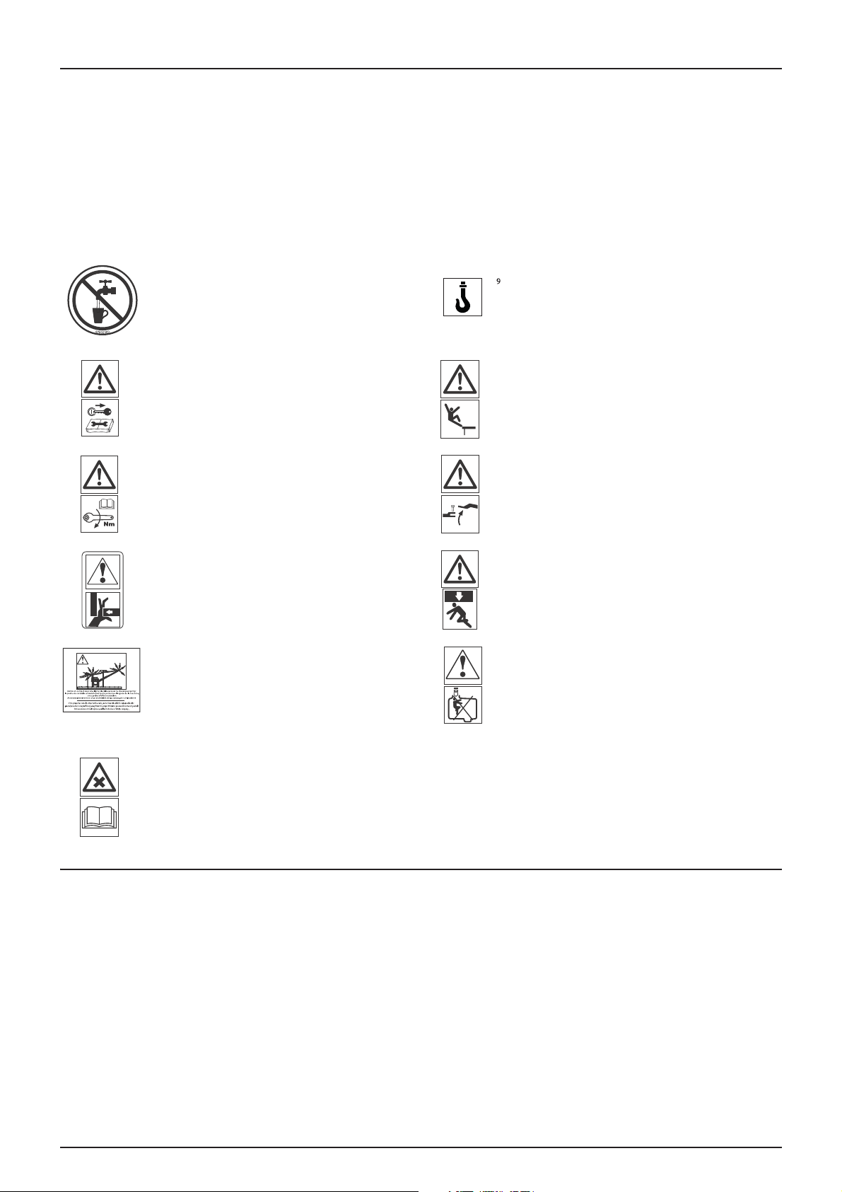
Clean water not for drinking!
Fill the rinsing tank and the hand wash tank
with clean water only.
This water must not be drunk.
Service!
Stop the engine and remove the ignition key
before doing any maintenance or repairs.
Service!
Tighten to the torque indicated in the user
manual.
Risk of crushing!
Keep hands out.
Risk of electrocution!
Keep well away from power lines.
Anchor point!
Risk of falling!
Do not stand on the platform or ladder during
use.
Risk of tipping over!
Be careful when uncoupling the sprayer.
Risk of crushing!
Do not stand under a raised and unsecured
load.
Risk of intoxication!
Entering the tank prohibited!
Handling phytopharmaceutical products!
Read recommendations relating to the
preparation of products carefully prior to
using the equipment. Follow the instructions
and safety advice during operation.
Regulations on the use of phytosanitary effluent
For more information on the use of effluent, refer to the APPLICATION TECHNIQUES manual in the 'Environmental Protection'
section.
11
Page 12

2- Safety instructions
12
Page 13

3 - Description
General information
Using the sprayer
This HARDI sprayer was designed for the application of phytopharmaceutical products and liquid fertilisers. It should be
used for this function only. Its use for other purposes is prohibited. If current regulations do not require you to obtain an
approved application certificate, it is still strongly recommended that you keep up to date your knowledge of protecting
crops and handling phytopharmaceutical products, to ensure the safety of persons and the environment during treatment.
Driving on the road
When you drive on a public road, you must follow the Highway Code and/or any other regulation applicable, especially
where required equipment is concerned, such as lighting, signalling, etc.
IMPORTANT! The maximum permitted speed for a tractor hitched to a towed sprayer is 25k.p.h. (French law). This
speed may differ in other countries. Check on the maximum permitted speed with the relevant authorities.
Ta nk
Made of impact-resistant polythene, resistant to UV light and chemicals, the main tank is round in shape to facilitate
cleaning. The manhole is accessible from the platform. This provides easy access for filling, cleaning the tank, etc. The sprayer
also has a rinsing tank and a hand wash tank. An optional gauge, easy to read and visible from the tractor cab, can be fitted
beside the platform.
Nominal capacity 2,500 litres.
Chassis
Compact and extremely robust, it is covered with an electrostatic lacquer which is resistant to chemicals and weather.
Bolting is treated with Delta-Magni against corrosion.
13
Page 14
3 - Description
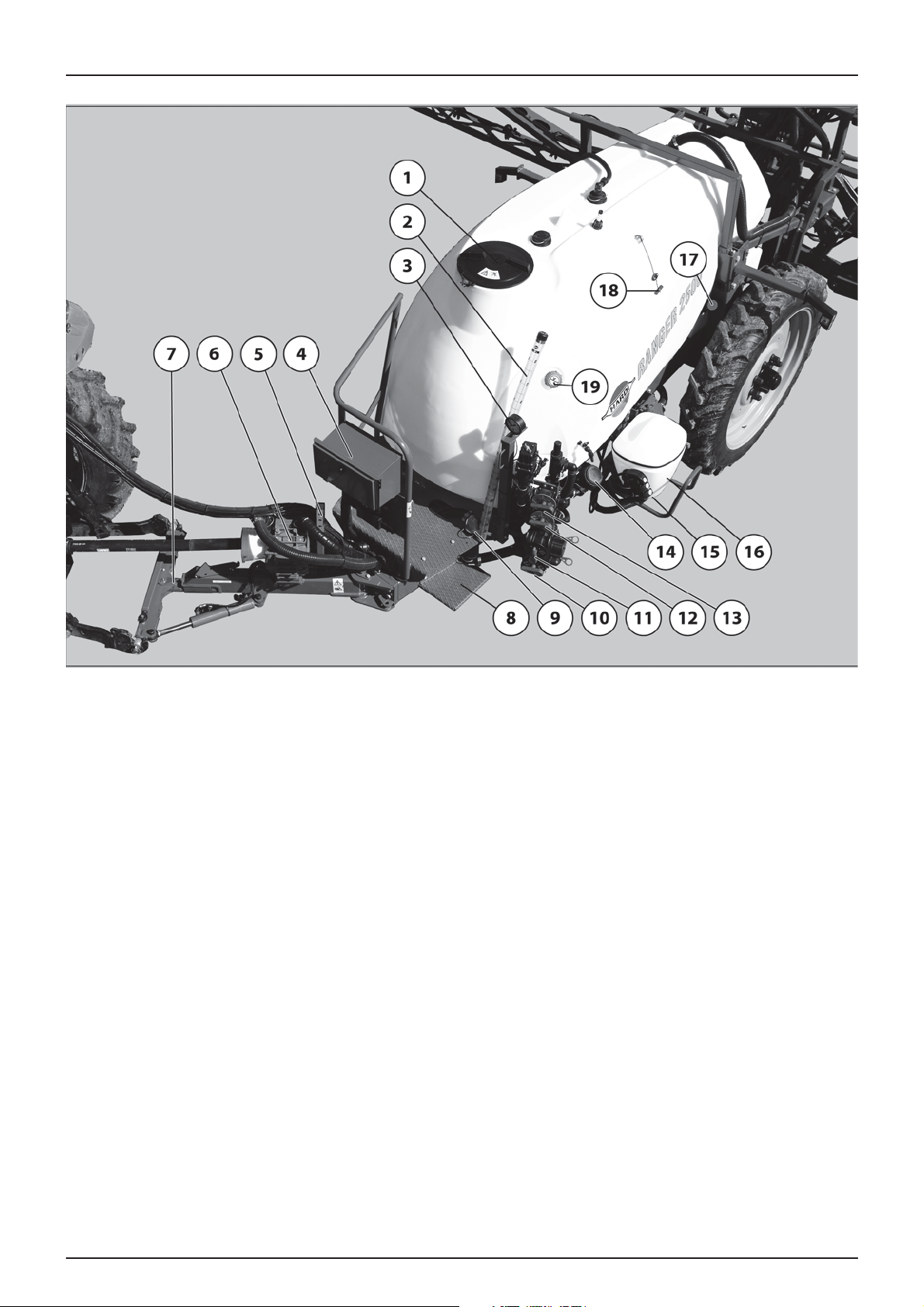
General view
1. Main tank cover
2. Main tank gauge
3. Pressure gauge
4. Storage box (optional)
5. Support leg
6. Pump
7. Hitch
8. Step
9. Suction filter
10. Suction valve
11. External filling valve
12. Agitation valve
13. Pressure valve
14. Cyclone filter
15. TurboFiller controls
16. TurboFiller
17. Rinsing tank cover
18. Drain valve control
19. Hand wash tank cover
14
Page 15
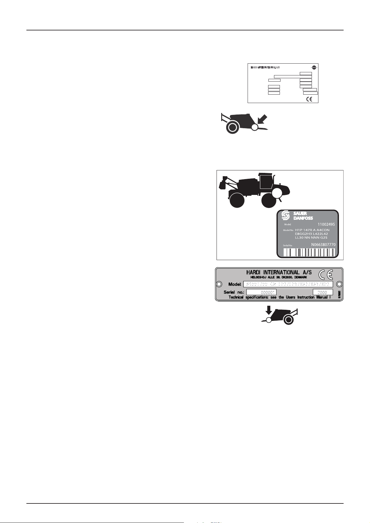
Identification plates
3 - Description
An identification plate, fixed to the chassis, indicates the manufacturer's
name, the model, the weight when empty, maximum height and the
maximum pressure in the hydraulic system (where there is one) and
spraying system.
The SERIAL NO. is the number for the complete equipment.
The chassis, boom frame and other main steel components also carry
identification plates showing the model and the part no. (not shown).
REFERENCE NO.: is the reference number for the basic chassis.
*1A500*- RG25- ALS
HARDI-INTERNATIONAL A/S
Marque : EVRARD
Type Variante Version
Année fabrication
Masses maximales admissibles
Essieu 1/attelage
Essieu 2
Essieu 3
RG25 ALS
2012
1200
4500
HELGESHOJ ALLE 38. DK263, DENMARK
kg
kg
kg
1A500
N° de série
2310
PV
5080
PTAC
PTRA
Réceptionné le
par la DRIRE
11/05/2012
GRAVELINES
kg
kg
kg
The CE identification plate fixed to the chassis shows the sprayer's
manufacturer, model and serial number.
15
Page 16
3 - Description
Spraying system
Pump
Six diaphragm pump, model 363 Standard = 540 rpm (6 splines). The design of the diaphragm pump is simple, with easily
accessible valves and diaphragms which isolate the moving parts from the mixture.
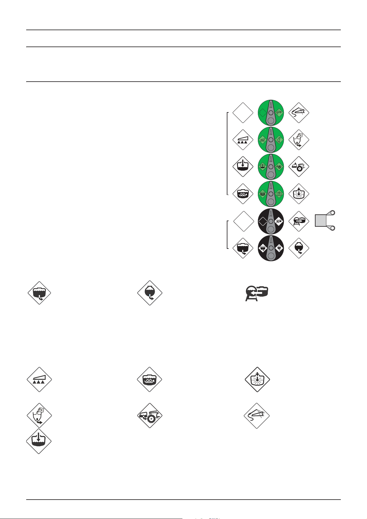
Valves and pictograms
The valves and pictograms are identified by a different colour for
different functions. The pictograms facilitate the operation of the valves.
The modular MANIFOLD principle facilitates the addition of optional
suction and discharge equipment. A return valve may be fitted on the
suction valve to improve draining of the sprayer prior to cleaning.
To activate a function, simply turn the handle to the desired function.
B
A. Suction valves (main and rinsing tanks, external suction).
B. Pressure valves (spraying, agitation, incorporation of products, tank
rinsing and equipment cleaning).
A
Suction MANIFOLD valves (A) - black disc
The arrow indicates the active function. Turn the handle to point the
arrow to the pictogram of the function required. If the arrow points to a
position without a pictogram (function not used), the valve is closed.
From the main tank From the rinsing tank From an external source
IMPORTANT! If a valve is difficult to turn or, conversely, turns too easily (= leak) - it should be checked. For more
information, refer to the "Maintenance" section.
Pressure MANIFOLD valves (B) - green disc
The arrow indicates the active function. Turn the handle to point the arrow to the pictogram of the function required. If the
arrow points to a position without a pictogram (function not used), the valve is closed.
To the spraying boom To the main tank agitation To the tank rinsing nozzle
To the product filler To a front tank External cleaning gun
16
Main tank filling
Page 17
3 - Description
Electrically controlled MANIFOLD valves (optional)
One or more Manifold valves may be fitted with an electrical control from a unit in the cab. To operate them manually, the
motor(s) must be disconnected from the power.
Regulation
The sprayer is equipped with EVC regulation.
Regulation is by EVC - Electrical valve control. The O/C (open/closed) control acts directly on the distribution valves,
providing a very quick response time. The setting unit, modular in design, is controlled electrically from a control unit in the
cab.
Diagrams - spraying system
Refer to sections Basic spraying system page 80 and Spraying system with options page 81
Filters
A suction filter is fitted on the left hand side of the sprayer, just in front of the MANIFOLD valves, recognisable by its red elbow
connection.
A Cyclone pressure filter is located on the left hand side of the equipment, just behind the Manifold valves. It has a built-in
self-cleaning function.
Optional boom filters can be fitted on each section..
All nozzles are fitted with filters.
All filters must be in good condition, in position and cleaned regularly. Take care with the choice of mesh size (see
"Application Techniques" manual).
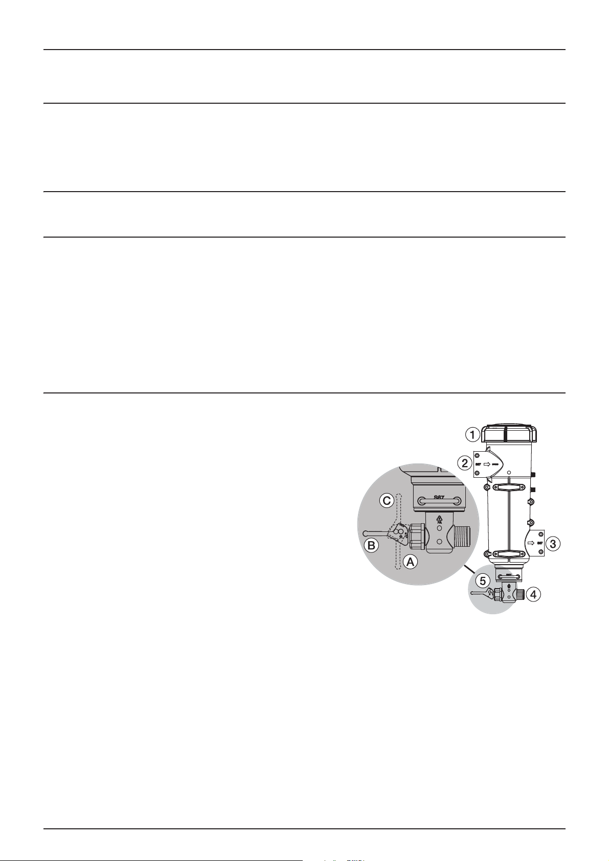
Cyclone Filter (optional)
With the Cyclone filter, all impurities contained in the mixture are
returned to the tank.
Operating diagram
1. Filter cover
2. Intake for the mixture from the pump
3. Outlet to the boom
4. Tank return
5. Return valve
The valve (5) has three positions identified by dots on the side of the
lever.
A. This position is marked with a dot: No return to tank. Position used
to rinse the boom when the tank is full. Or to have the pump's full
capacity available.
B. This position is marked with two dots: Normal working position. With a return to tank to prevent any blockage during
treatment. Position also used to rinse the boom when the tank is empty.
C. This position is marked with three dots: Turbo function to unblock the filter. Lift and hold the lever for a few moments.
The increased return to the tank cleans the filter.
IMPORTANT! The use of position C does not guarantee that the filter is clean. Check the condition of the filter and
clean it regularly. If necessary see Every 10 hours - Cyclone filter page 58.
17
Page 18
3 - Description
A
B
DANGER! Never open the Cyclone filter before valves (1) and (2)
€
are closed (turned to the neutral position). Otherwise, the
mixture could escape and splash you through the filter cover.
TurboFiller
Before use
Pull the lever (A) to unlock.
Use the handle (B) to lower the TurboFiller until it locks in the down
position.
After use
Use the handle to lift the TurboFiller back to the upper position
until it locks into place.
WARNING! Before using the unlocking lever (A), you must hold
±
the handle to prevent any unwanted movement of the
TurboFiller!
TurboFiller suction valve
The locked opening valve is used simultaneously with the TurboFiller. It is opened just
before pouring the products into the filler.
Adding products without using the Turbo deflector.
Turbo deflector control
When locked in the open position, this valve activates a continuous vortex at the bottom
of the TurboFiller hopper.
Turbo deflector control
18
Page 19

Package and drum rinsing control
The upper lever has two functions:
1. When the TurboFiller lid is open, it can be used to clean empty packages by turning
drums upside down over the rotary rinsing nozzle in the middle of the hopper.
When the TurboFiller lid is closed, it rinses the hopper after the products have been added
to the tank.
Rinsing product packaging and drums
For more information on using the rinsing control, refer to section Cleaning the TurboFiller page 46
3 - Description
19
Page 20

3 - Description
AB C
D
Boom
Boom and terminology
The sprayer is equipped with a TR2 boom. It is held by trapeze arms fixed to the tank's chassis.
The trapeze arms allow the boom to remain horizontal when unfolded and protect it from impacts and vibrations on uneven
terrain. They ensure the longevity of the boom and improve its stability, resulting in more accurate application.
Booms are available in 18, 20, 21, 22 and 24m working widths. All booms are fitted with folding end arms.
The terminology for dual-fold booms is as follows
A - Folding end arm
B - Outer arm
C - Inner arm
D - Central section
Model
Equipment
Function control Tractor valve
Independent folding of
the ends
Hydraulic tilt corrector
Boom tilt
1 single acting control valve
Tractor valves
1 double acting control valve
TR2 Y TR2 V TR2 Z
control
optional
Tractor valve
control
By hydraulic solenoid valves
and unit in the cab
no yes
yes
no
1 single acting control valve
+
+
free return
yes
20
Page 21
Equipment
Hitch with hydraulic drawbar (optional)
The sprayer can be equipped with a hitch with a hydraulic drawbar. This
allows the sprayer to be turned a little later when the tractor starts to
turn at headlands, compared to a conventional hitch tongue. This results
in a tighter turning circle, allowing the size of headlands to be reduced.
It also makes traces in the headlands easier to follow.
The articulated hitch with tilt correction has an offset correction device.
The hitch carries out the same function but the tilt correction allows it to
also be used on slopes.
IMPORTANT! The offset correction is controlled by the tractor's
hydraulic control valves.
3 - Description
Step
A step on the left hand side of the sprayer gives access to the platform.
Platform
The platform provides access to the lids on the hand wash tank and the
main tank.
21
Page 22
3 - Description
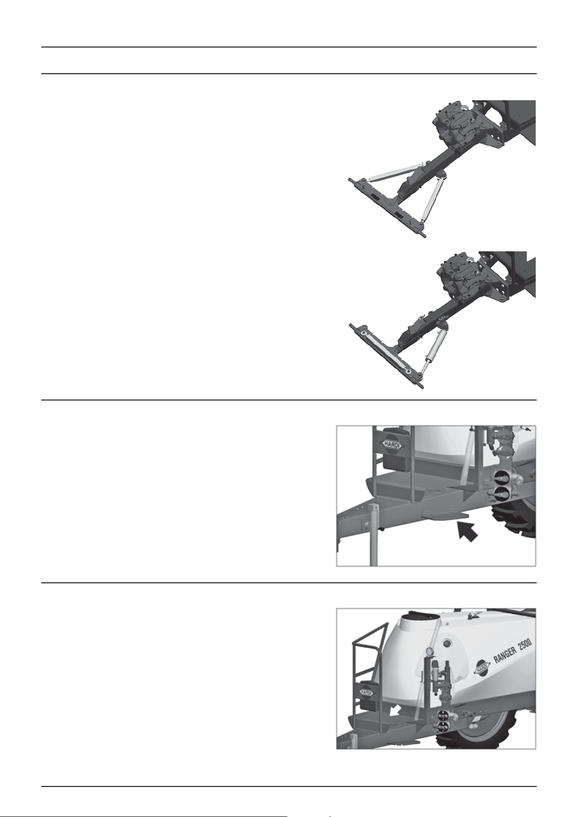
Main tank gauge
The gauge indicates the level of the mixture in the main tank. The scale
is written in litres or Imp./US gallons (for some countries).
The gauge is only an indication of the level in the tank. The total
variation in the accuracy of the level is 7.5% for a tank filled to less than
20% of its capacity. For a tank filled to more than 20%, the accuracy
variation is 5%.
IMPORTANT! For greater accuracy, a filling meter can be fitted as
an option.
Boom pressure gauge
The pressure gauge is located on the platform, above the Manifold
valves. It measures the working pressure in the boom's pipes right next
to the nozzles.
The flow rates shown in the nozzle flow tables are always calculated
according to the pressure measured at the nozzles. When calibrating, as
when working, the pressure should be set using this gauge.
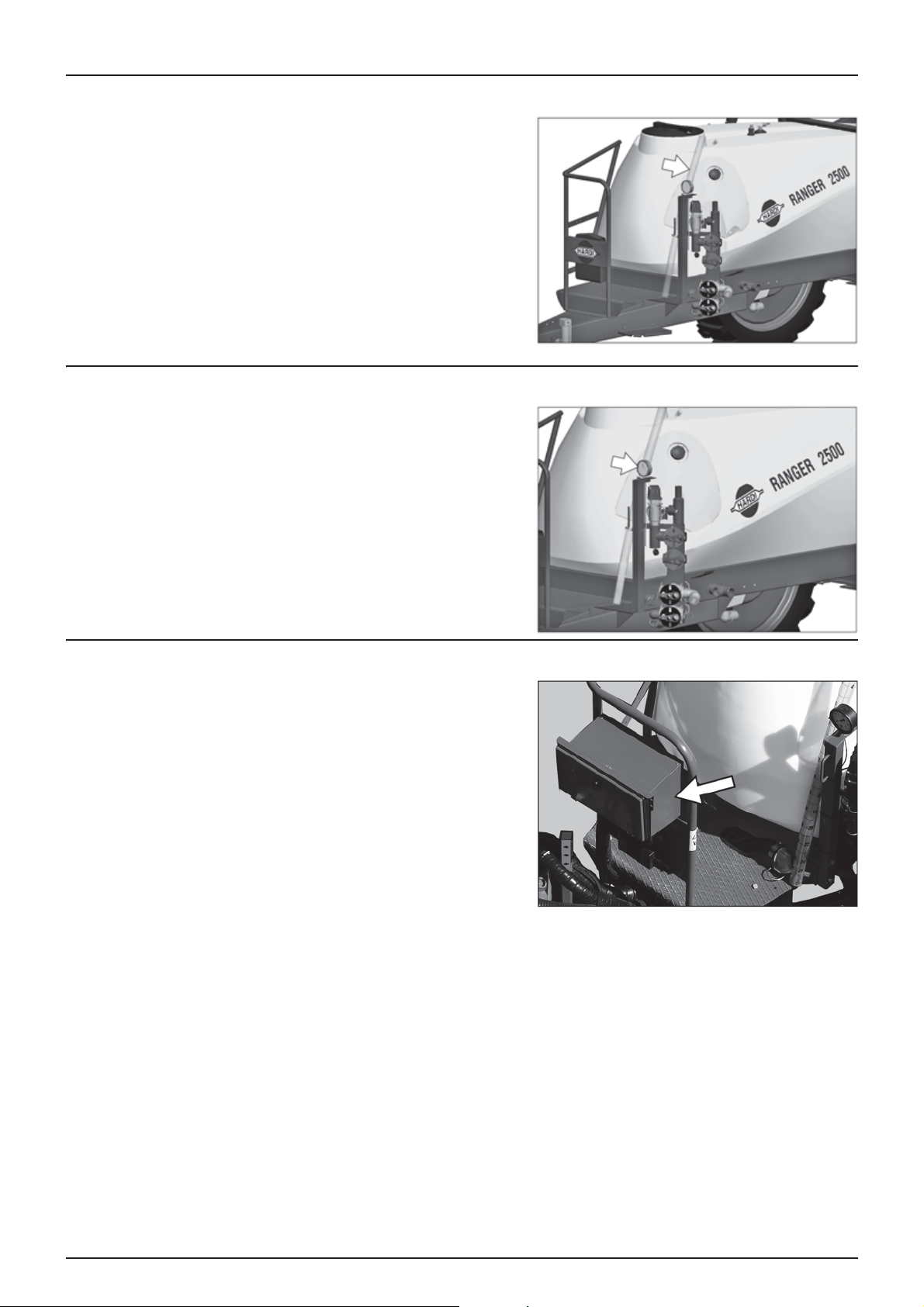
Storage box (optional)
A storage box can be fitted to the platform rail. It is intended for the
storage of protective equipment such as clean clothing, soap for hand
washing, etc. The box is divided into two compartments, allowing clean
items to be separated from dirty ones.
WARNING! Although the box is intended for storing clean items,
±
it should never be used for storing food, drinks or any other
consumable.
22
Page 23
3 - Description
1
7
5
4
6
8
2
3
External cleaning equipment (optional)
This equipment comprises a reel with a hose and a spray gun for rinsing the sprayer with clean water while still in the field.
The external cleaning equipment is located to the right of the sprayer.
1. Reel
2. Spray gun
3. Rotating hose reel bracket
For information on using the hose reel, refer to the relevant section.
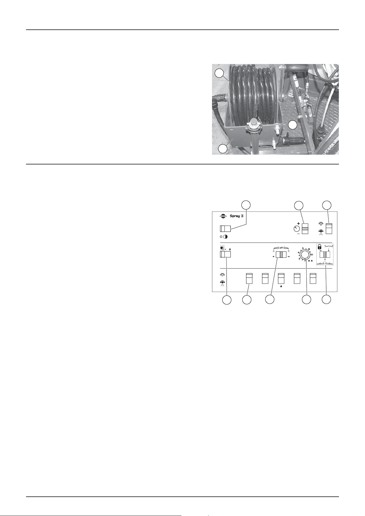
TR2 Y version control unit
'Sprayll' hydraulic and spraying control
The switches on the Spraying unit control the following functions:
1
2
3
1. Switching on the unit.
2. Regulating the working pressure. Regulates the working pressure.
3. General spraying Open/Closed. Opens or closes all sections.
Closed position at the top and Open position at the bottom.
4. End nozzles (Left/OFF/Right). If end nozzles are fitted, opens them
on each side. Closed position in the middle.
5. Not used
6. Central frame locking selection - Boom Open/Closed - Tilt
7. Individual spray section control valves Open/Closed.
Closed position at the top and Open position at the bottom.
8. Boom lights (optional)/Tank bottom dilution (optional)
For more information on using the spraying functions, refer to section Spray controls page 48
For more information on using the hydraulic functions, refer to section TR2 Y boom hydraulic controls page 37
23
Page 24
3 - Description
1
7
5
4
6
8
2
3
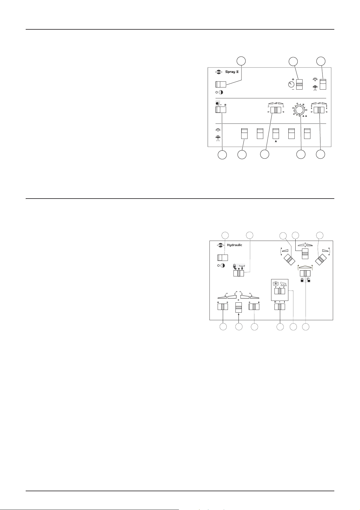
'Sprayll' spraying control
The switches on the spraying control unit control the following functions
1. Switching on the unit.
2. Regulating the working pressure. Regulates the working pressure.
3. General spraying Open/Closed. Opens or closes all sections.
Closed position at the top and Open position at the bottom.
4. End nozzles (Left/OFF/Right). If end nozzles are fitted, opens them
on each side. Closed position in the middle.
5. Not used
6. Not used.
7. Individual spray section control valves Open/Closed.
Closed position at the top and Open position at the bottom.
8. Boom lights (optional).
For more details on using the spraying functions, refer to section Spray controls page 48
'Hydraulic' control
The switches on the hydraulic control unit control the following functions:
1. M/A supply
2. Selection of central frame locking or tilt correction
3. Left boom tilt - TR2 Z version only
4. Boom raise/lower
5. Right boom tilt - TR2 Z version only
6. Fold out/fold in left arm
7. Inner arm simultaneous fold out/fold in
8. Fold out/fold in right arm
9. Hydraulic drawbar
10. Tank bottom dilution (optional)
11. Central frame locking/tilt correction control
For more information on using the hydraulic functions, refer to section TR2 V and TR2 Z boom hydraulic controls page 39
1
6
2
H2o
7
8
3
H2o
9
4 5
11
10
24
Page 25
4 - Sprayer set-up
General information
Precautions before use
Although the sprayer is factory protected with a resistant coating on its metal parts, nuts and bolts etc., it is recommended
that you apply a coat of anti-corrosion oil (Castrol Rustillo or Shell Ensis Fluid) to all metal parts, to prevent agropharmaceutical products and liquid fertilisers from discolouring the paintwork.
If you do this before you use the equipment for the first time, future cleaning will be easier and the paintwork will not dull.
Re-apply the treatment regularly, as soon as the protective film disappears.
Unloading the sprayer
Unloading may require the use of a crane or forklift truck. If this is the
case, use the anchor points provided for this purpose. Ensure the slings
or chains used can support the load.
IMPORTANT! only lift the sprayer when the tanks are empty.
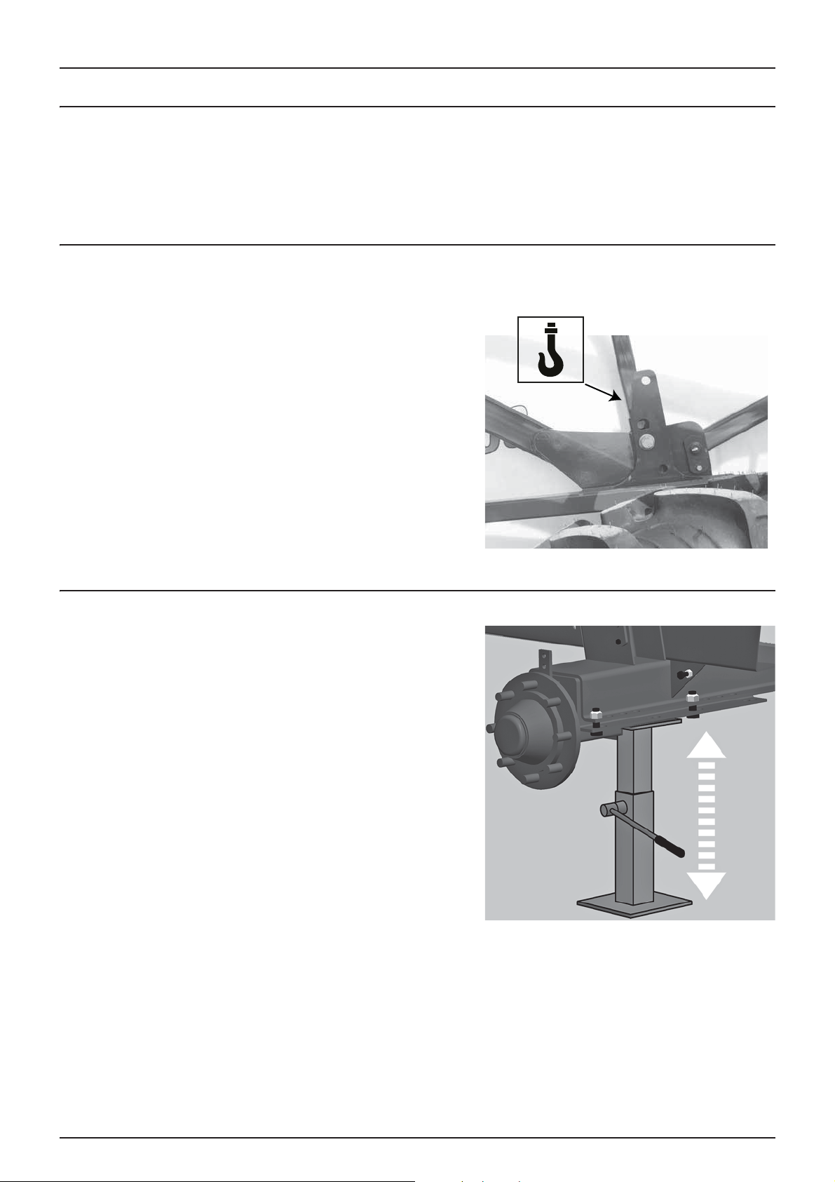
Lifting the sprayer with a jack
To change a wheel, replace a bearing, etc., lift the sprayer by positioning
the jack under the axle as shown.
DANGER! The sprayer must be placed on firm level ground, so
€
that it will not fall off the jack.
IMPORTANT! For greater safety, chock the opposite wheel!
25
Page 26
4 - Sprayer set-up
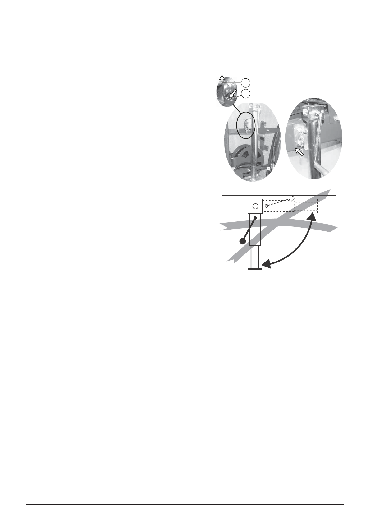
Support leg
NOTE! The strength of the support leg and the jack is designed to support the weight on the hitch tongue, on flat
÷
ground, when the tank is full.
To position the support leg:
1. Remove the pin (1) and pull the shaft (2)
2. Position the support leg with the shaft on the hitch tongue,
replace the pin
3. Turn the handle to lower the support leg to the ground.
4. When the leg is fully supporting the sprayer, you can unhitch the
sprayer from the tractor.
When the sprayer is hitched to the tractor, the leg is positioned on the
support provided for this purpose.
2
1
26
Page 27
4 - Sprayer set-up
Transmission shaft
User safety
1. ALWAYS SWITCH OFF THE ENGINE before connecting the transmission shaft to the tractor's PTO drive - most PTO drive
can be rotated by hand to make it easier to align the splines.
2. When you connect the shaft, check that it is LOCKED. Push and pull the shaft until it engages.
3. Keep guards and chains in good condition and check that all rotating parts are properly protected, including the
journal crosses at each end of the shaft. Do not use the transmission shaft without guards.
4. Do not touch the transmission shaft while it is rotating. Do not climb on it. Safety distance: 1.50m. NEVER step over a
rotating shaft to get to the other side of the equipment.
5. To prevent guards from being pushed out of the way, attach safety chains but leave sufficient slack.
6. Check that the guards around the tractor's PTO drive and shaft on the equipment side are in good condition.
7. ALWAYS STOP THE ENGINE and remove the ignition key before doing any maintenance or repair to the shaft or the
equipment.
DANGER! UNGUARDED ROTATING TRANSMISSION SHAFTS ARE A DANGER TO LIFE.
€
Connecting the transmission shaft
Always check the manufacturer's user manual before connecting the
transmission shaft!
When you connect the shaft for the first time, follow this procedure:
1. Hitch the sprayer to the tractor and position it with the tractor and
the PTO drive on the spray pump side as close as possible.
2. Stop the engine and remove the ignition key.
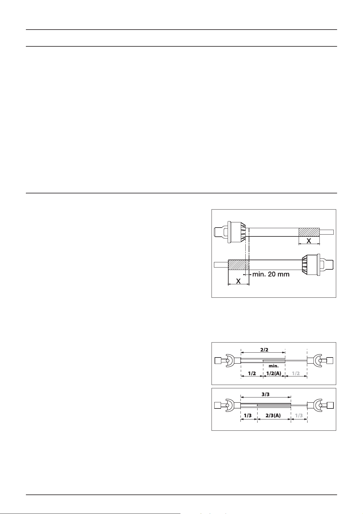
3. To shorten the transmission shaft, separate the two parts of the
shaft. Fit the two parts on the tractor side and sprayer side and
measure by how much you need to shorten the shaft. Mark the
guards, so that they can be shortened by the same amount.
WARNING! Only shorten the shaft if absolutely necessary!
±
WARNING! The shaft must always have a minimum overlap of half its length!
±
The overlap (A) recommended between the two parts of the shaft
equals two thirds of its total length. The minimum overlap (A) must be
half the length.
DANGER! Since transmission shafts are potentially dangerous,
€
always consult the manufacturer's user manual before making
any modification.
27
Page 28

4 - Sprayer set-up
The transmission shaft's speed is limited to 540 rpm.
A pictogram reminds you of the dangers and the speed limit relating to transmission shafts. A speed greater than
€
540 rpm could cause serious injury by damaging components on the sprayer or the transmission shaft.
28
Page 29

4 - Sprayer set-up
Mechanical equipment
Hitches
The hitch is equipped with a ring as standard, or with an optional articulated system with or without offset correction.
All hitches are fixed using six bolts secured by locknuts under the sprayer, close to the rear axle. Also, the hitch is supported
by two bolts secured by locknuts under the platform.
Ring hitches have an extension piece, secured with six bolts.
1. Ring hitch
2. Extension
3. Ring hitch fixing screw on the extension
4. Ring
For more information, refer to section Every 1,000 hours - Hitch
extension page 61
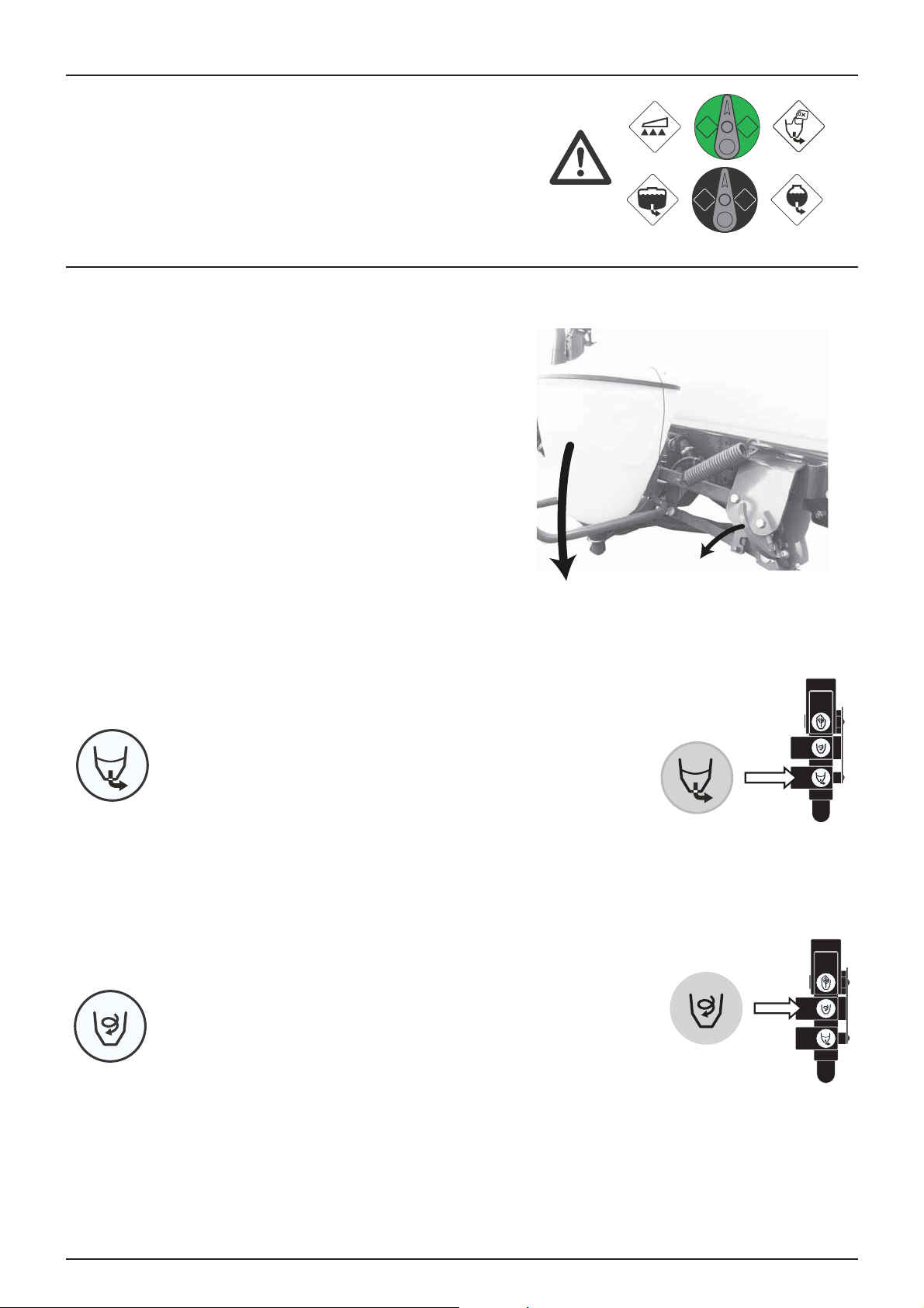
Articulated hitch with tilt correction (optional)
When the sprayer is hitched to the tractor, move the tie-rods from
position (B) to position (A).
Position of tie-rods:
A. Spraying.
B. Driving on the road.
DANGER! While driving on public roads, the tie rods must be in
€
position (B). If this is not the case, the sprayer could tip on bends
or when turning.
2
1
Where the articulated hitch is equipped with an offset corrector, remove
the tie rod from position (D) and store it in position (B). Pivot the cylinder
from position (C) to position (A).
Position of the tie-rod/cylinder:
A. Spraying with offset correction.
B. Tie-rod storage (not used during work).
C. Driving on the road.
D. Driving on the road.
DANGER! While driving on public roads, the cylinder and tie rods
€
must be in positions (C) and (D). If this is not the case, the sprayer could tip on bends or when turning.
WARNI NG! To pre vent any dama ge to the drawbar or chassis, the cy linder should not be under pressure when driving
±
on the roads (C).
29
Page 30

4 - Sprayer set-up
Track width, axles and wheels
Modifying the track width
The sprayer's track width can be modified in stages.
The tables show the track widths possible, twice the distance the axle (X)
can slide from the middle of the sprayer (C) and the position of the
wheel discs (A) and (B).
Wheel discs Offset Consequences for the track
width
ANegative Narrower
B Positive Wider
Modification procedure
1. Measure the track width (centre of the right tyre to the centre of
the left tyre). The increase or decrease in track width must be
divided between the two sides.
2. Hitch the sprayer to the tractor and engage the parking brake.
3. Place chocks in front of and behind the right hand wheel. Lift up
the left wheel and make the equipment secure.
4. Loosen the bolts (A) on the left stub-axle.
5. Loosen the setting screw on the hand brake control lever.
6. Slide the axle. If necessary, use tools to assist.
7. Tighten the bolts (A) to a torque of 250Nm.
8. Repeat the operation for the right hand wheel.
9. Check that the distance from the centre of the tyre to the centre of
the chassis is the same on both sides.
10. Tighten the bolts, including those on the wheels, to the indicated
torques after 8 hours of work.
IMPORTANT! The wider the track width, the more stable the sprayer. We recommend that you work with the widest
possible track width.
WARNING! Position the jack under the axle and lift the wheel, so that there is no weight on the flanges, before
tightening them to the specified torque.
Tyre inflation pressures
Check tyre pressures. Refer to section Tyre specifications page 78
An incorrectly inflated tyre could burst and will wear more quickly.
±
30
Page 31

Brakes
a0
b1
b0
a1
X
Parking and safety brake
There are two operating modes for the parking brake, determined by
the position of the pawl (A). To change from one mode to the other, turn
the pawl.
Position Pressure position Function
1 Pressing against the ratchet To release the hand brake
2 Tip clear of the ratchet To engage the hand/safety brake
To release the hand brake
• Put the pawl in position 1.
• Pull the lever gently forward to release the yoke from the toothed
wheel, then push the lever fully backwards.
To engage the hand brake
• Put the pawl in position 2.
• Pull the lever firmly forward until it is fully engaged.
Safety brake:
• Put the pawl in position 2.
4 - Sprayer set-up
• Adjust and solidly fix the link on the parking brake wire to a fixed
point on the tractor. If the sprayer accidentally comes unhitched
whilst moving, the wire will activate the parking brake before
breaking.
IMPORTANT! For the safety brake to operate correctly without
damaging the hand brake, use a wire with a break link.
WARNING! Release the parking brake before moving.
±
Hydraulic braking
How the hydraulic braking device is fitted depends on the tyres used.
If they are changed, it is essential that you use the brake control cylinder
fixing points indicated.
Tyres Distance (X) in mm Brake cylinder position
270/95R38
other tyres 180 b0 - b1
See section Tyre specifications page 78.
152 a0 - a1
X
31
Page 32
4 - Sprayer set-up
Vers distributeur
simple effet
Vers distributeur
double effet
Frein
hydraulique
1
2
3
4
RETUR
RETUR
TRYK
TRYK
Hydraulic system
General information
Check the cleanliness of the oil intakes before you connect them!
After manoeuvring the boom and filling the oil system, check the level of hydraulic oil in the tractor and top up if necessary.
The hydraulic hoses' connection to the tractor differs according to the configuration of the sprayer. For more information,
refer to section Boom and terminology page 20
Check that the hydraulic system on your tractor is compatible with the RANGER TR2 system. If you are in any doubt,
±
consult your HARDI-EVRARD dealer.
If controlled by a double acting control valve on the tractor, failure to comply with the oil's direction of circulation
±
could cause uncontrolled movements of the boom.
DANGER! Commissioning the hydraulic system must be performed with great care. There could be air in the system
€
that would cause undesirable movements of the boom.
DANGER! Hydraulic leaks: Never attempt to identify the location of a leak in the hydraulic system with your bare
€
hands. The high pressure could cause oil to penetrate the skin.
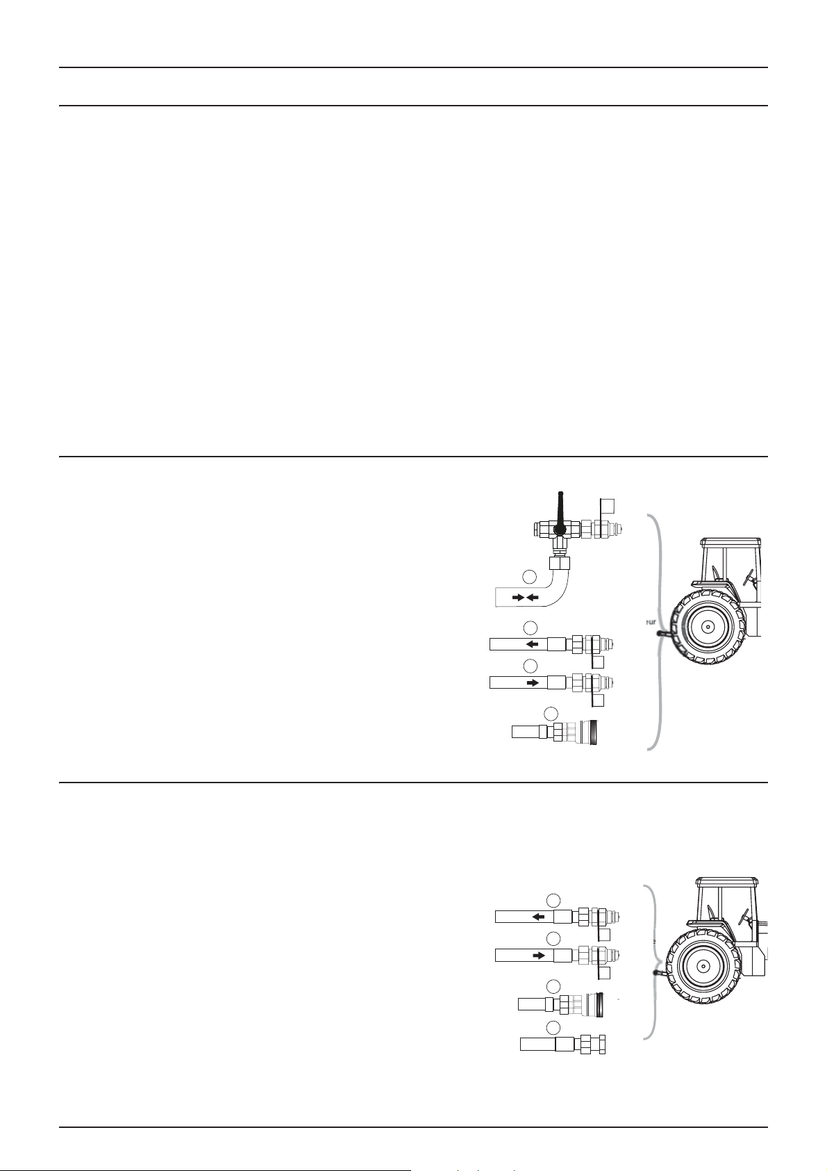
Version TR2 Y hydraulic connection
1. Hose (TRYK/RETUR) with isolation valve connected to a single
acting control valve for controlling the raising/lowering of the
boom.
2. Hose (TRYK) connected to the outlet of a doubling acting control
valve.
3. Hose (RETUR) connected to a double acting control valve
for controlling the opening and closing of the boom or the tilt
control.
4. Hydraulic brake hose.
For the detailed use of the hydraulic controls, refer to section
÷
TR2 Y boom hydraulic controls page 37
Version TR2 V and TR2 Z hydraulic connection
The hydraulic system requires: a single acting control valve and a free return to control the boom's folding/unfolding
functions. The hydraulic hoses are marked with an arrow which indicates the direction of circulation of the oil.
The hydraulic system requires an oil flow of between 25 and
30 litres/minute and a minimum pressure of 170 bar.
RETUR
1
TRYK
2
3
4
Vers distributeur
double effet
Frein
hydraulique
Load Sensing (LS)
1. Hose (TRYK) connected to the outlet of a single acting control
valve
2. Hose (RETUR) connected to a free return
3. Hydraulic brake hose
4. Load Sensing (LS) hose (optional)
÷
For the detailed use of the hydraulic controls, refer to section
TR2 V and TR2 Z boom hydraulic controls page 39.
32
Page 33

Open centre hydraulic block (optional)
If the tractor's hydraulic system is of the open centre or load sensing
type, an open centre hydraulic block is required.
The valve (1) on the side of the block is factory set for an open centre. But
if the tractor has a closed centre (and/or load sensing) system, this valve
must be screwed all the way in.
Some tractors can use load sensing (LS) without connecting an external
load sensor. But if the optimum load control pressure is not reached, an
external load sensor (3) must be fitted. Ask your tractor dealer for the
correct setting and connection.
WARNING! The valves must be adjusted according to the model
±
of tractor before you operate the hydraulics. If you do not know
what type of hydraulic system your tractor has, contact your
dealer.
Settings table for the valves on the block:
Valve no. 1 2 3 (LS port )
Open centre Unscrewed Unscrewed Free
Closed centre Screwed Screwed Free
Load sensing (LS) Screwed Unscrewed Connected
4 - Sprayer set-up
*if the tractor requires a pressure discharge, consult your tractor dealer.
WARNING! Always check that the valve (1) to select open centre/closed centre is indeed fully screwed in or
±
unscrewed. Failure to do this could result in vital components in the tractor's hydraulic pump being damaged.
WARNING! It is essential that the load sensor connectors are always kept perfectly clean. Failure to ensure that this is
±
the case could result in impurities entering the pump and damaging its components.
33
Page 34
4 - Sprayer set-up
Electrical connections
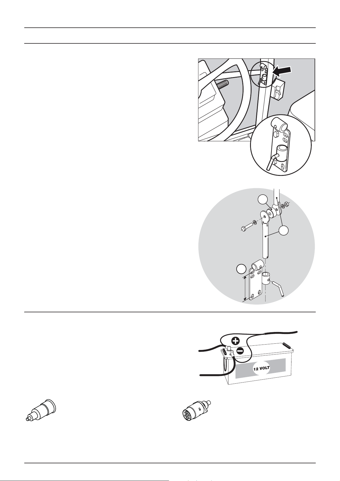
Installing the control unit supports
Position the control units in the most suitable place in the tractor cab.
The best position is to the right of the driver's seat.
The support (A) supplied is drilled with holes spaced at 100 and 120mm
and is suitable for most tractors. Tapped fixing holes are sometimes
concealed inside the front post protector. See the tractor's user manual
for the fixings in the cab.
Three tubes (B) are supplied. You can use 1, 2 or all 3 of them. They can
be bent and shortened. A spacer (C) is also supplied to allow for other
types of fitting. It is up to you to choose the best solution for your tractor.
The tube (B) is adjustable, so that, when correctly oriented, all the units
will be in line.
Electrical supply
Power required: 12V DC. Always check the polarity! To ensure sufficient
power and correct operation of the electrical equipment, use the
correct size of cables and fuses. The plugs supplied comply with the
most recent standards for tractors. If they do not fit, remove them and
connect the wires directly to the socket on the tractor.
C
B
A
100 -120mm
The number and type of plugs can vary for the same sprayer, depending
on its equipment.
CIGARETTE LIGHTER
The spraying control unit requires:
2.5mm² cable, 10 Amp fuse
The hydraulic control unit requires:
4.0mm² cable, 16 Amp fuse
34
ROAD SIGNALLING SOCKET
Page 35

Sprayer speed sensor
The speed sensor and holed disc are located in the sprayer's right side
wheel.
It works by induction and has to pass over a metal projection to trigger
a signal. A holed disc is used to do this. It has to be adjusted so that it
senses in the middle of the disc's holes (when vertical). The
recommended distance between the metal part and the sensor (A) is
between 3 and 6mm. Check that this is so over the whole circumference.
IMPORTANT! Correct operation is indicated by a constant flashing
of the sensor when you turn the holed disc.
Road signalling
4 - Sprayer set-up
Connect the plug to the 7-pin socket on the tractor and check the operation of the rear lights, stop lights, side lights and
indicators on each side before moving off.
The wiring complies with ISO 1724. See section Electrical connections page 82.
IMPORTANT! SWITCH OFF working lights when driving on public roads!
35
Page 36

4 - Sprayer set-up
Spraying system
Use of electrical EVC adjustment
Before spraying, it is necessary to adjust the setting using clean water
(no agro-pharmaceutical products).
1. Select the appropriate nozzles for the treatment by turning the
Triplet nozzle holder. Check that all the nozzles are of the same
type and size. Refer to the "Application Techniques" manual.
2. Set the On/Off switch to On on the spraying control unit.
3. Set all the switches on the sections to ON on the spraying control
unit.
4. Lower the pressure regulation switch until the emergency lever on
the control valve stops turning (minimum pressure).
5. While stationary, rotate the PTO drive and with it the pump at the
planned speed. The PTO drive should rotate at between 300 and 600 rpm (pump 540 rpm) or between 650 and
1,100 rpm (pump 1,000 rpm).
6. Lift the pressure setting switch on the spraying control unit until the pressure gauge indicates the required pressure.
PRESSURE COMPENSATION SETTING:
7. Close the first section on the spraying control unit.
8. Turn the compensation screw until the pressure gauge indicates the required pressure again.
9. Open the section again.
10. Set the other sections one by one, using the same method.
IMPORTANT! A NEW PRESSURE COMPENSATION SETTING WILL BE NECESSARY IF:
1. YOU USE NOZZLES OF A DIFFERENT SIZE
2. THE FLOW THROUGH THE NOZZLES INCREASES DUE TO WEAR
36
Page 37

5 - Operation
Boom
Safety instructions
The boom must never be unfolded/folded while the sprayer is moving. Only use the unfolding/folding functions when the
sprayer is stationary. Any failure to comply with this rule could damage the boom.
DANGER! Before unfolding the boom, hitch the sprayer to the tractor to prevent it tipping over.
€
DANGER! Before unfolding or folding the boom, check that nothing and no one is within its field of movement.
€
DANGER! When you are close to high voltage lines, follow the advice below very carefully:
€
Never unfold/fold the boom close to overhead power lines.
It could touch the lines during accidental movements.
IMPORTANT! A warning sticker (ref. 978448) is delivered with the
equipment. Display this in the cab, visible from the driver's seat.
IMPORTANT! The boom must be unfolded/folded on even
ground.
TR2 Y boom hydraulic controls
WARNING! Before using the unfolding/folding functions, check that the frame is locked in place.
±
WARNING! The boom unfolding/folding functions must only be used when the sprayer is stationary. Otherwise the
±
boom could be damaged.
To unfold the TR2 Y boom, proceed as follows:
1
8
7
4
2
3
5
6
Control of the boom's hydraulic functions depends on the direction in which the hydraulic hoses are connected and
±
the control of the tractor's single and double acting valves.
For more details on identifying the hoses, refer to section Version TR2 Y hydraulic connection page 32
÷
37
Page 38

5 - Operation
Ouvert
1. Turn the lever on the single acting hose isolation valve, as shown
in the illustration.
Fermé
TRYK
RETUR
The isolation valve allows the hose to be connected or disconnected without pressure on the tractor's oil intake.
±
This isolation valve must be closed during transport and periods of storage.
Ensure that the central frame is locked before unfolding the boom. If this is not the case, lock the central frame by moving
the switch (6) to the 'tilt' position and then operating the tractor's double acting control valve.
2. Release the boom from its transport supports by activating the tractor's double acting control valve.
3. Move the switch (6) to the central position, then operate the tractor's double acting control valve to unfold the boom.
4. Set the boom to working height above the crop or the ground by activating the tractor's single acting control valve.
5. Move the switch (6) to the 'padlock' position and then operate the tractor's double acting control valve to de-activate
the locking of the central frame.
1. If necessary, move the switch (6) to the 'tilt' position and then operate the tractor's double acting control valve to adjust
the incline of the boom.
To fold the boom, proceed as follows:
1. Move the switch (6) to the 'tilt' position and then operate the tractor's double acting control valve to position the frame
in the centred position.
2. Move the switch (6) to the 'padlock' position and then operate the tractor's double acting control valve to activate the
central frame locking.
3. Activate the tractor's single acting control valve to raise the boom.
4. Move the switch (6) to the central position and then operate the tractor's double acting control valve to fold the boom.
5. Activate the tractor's single acting control valve to place the boom on the transport supports.
6. Close the supply hose isolation valve.
Before making any movement, ensure the central frame is not touching the sprayer's wheels.
38
Page 39

5 - Operation
TR2 V and TR2 Z boom hydraulic controls
WARNING! Before using the unfolding/folding functions, check that the frame is properly locked in place.
±
WARNING! The boom unfolding/folding functions must only be used when the sprayer is stationary. Otherwise the
±
boom could be damaged.
WARNING! Do not raise the boom tilt to the vertical before folding the three arms. The same applies during the
±
normal folding procedure. Otherwise the boom could be damaged.
To unfold the TR2 V and TR2 Z boom, proceed as follows:
For more details on identifying the hoses, refer to section
÷
Version TR2 V and TR2 Z hydraulic connection page 32
1
6
1. Secure the central frame lock by selecting locking (2) and then engaging boom locking (11).
2. Release the boom from its transport supports by lifting switch (4)
3. Simultaneously unfold the inner arms by lowering switch (7).
4. Lower the boom tilt by lowering switches (3) and (5).
5. Unfold the left and right outer arms by pushing switches (6) and (8) outwards.
6. Set the boom to working height above the crop or ground by operating switch (4).
2
7
8
4 5
3
H2o
H2o
11
10
9
7. Unlock the boom by moving switch (2) to the 'padlock' position and then operating switch (11).
8. If necessary, adjust the boom's incline by moving switch (2) and then operating switch (11).
To fold the boom, proceed as follows:
1. Position the boom horizontally by moving switch (2) to the 'padlock' position and then operating switch (11).
2. Lock the central frame by moving switch (2) to the 'padlock' position and then operating switch (11).
3. Raise switch (4) to lift the boom as far as possible.
4. Push switches (6) and (8) in to fold the boom.
5. Raise switches (3) and (5) to raise the boom's variable geometries.
6. Fold the outer arms by raising switch (7). Ensure that the arms are indeed in contact with the guide rail.
7. Lower the boom by lowering switch (4), until it rests on the transport supports.
39
Page 40

5 - Operation
Equipment
Articulated hitch with hydraulic tilt correction (optional)
With the articulated hitch, slow down at the end of the field and turn
around. The maximum permitted turning circle (A) is 70°. Pay attention
to your speed when turning. For more information Driving technique
with the articulated hitch page 40.
The articulated hitch with offset correction operates in the same way
but, on slopes, it is useful to have correction in order to remain on line.
Operate the tractor's hydraulic control valve to offset the sprayer by a
distance (B), so that it remains on the working line.
Driving technique with the articulated hitch
The behaviour of a trailer fitted with an articulated hitch is different from
that of a normal trailer. In tracking position, the centre of gravity is
further from the stability line than for normal equipment. Compared to
a normal trailer, a trailer in tracking version has less stability when
turning, especially on sloping ground (B).
To prevent too great a pitch, follow this advice:
1. Avoid sudden or tight turns.
2. Slow down before taking a bend or turning and drive slowly at a
constant speed throughout the turn.
3. Do not slow down or brake suddenly; do not stop suddenly on a
bend or when turning on sloping land when the sprayer is in
tracking mode.
4. Take care when turning on uneven ground.
5. Choose the widest track width (A) possible.
6. The hydraulic system must operate correctly to obtain good stability.
40
Page 41

5 - Operation
Spraying system
General information
Refer to the Application Techniques manual for the use of filters, nozzles, etc. and their combinations when used in specific
applications.
Filling/cleaning zone - Rules
When filling the sprayer's tank, it is essential that any undesirable contamination from agro-pharmaceutical products is
avoided, in order to protect the water table.
A. If filling is always performed in the same place, a special filling/cleaning zone should be set up. It should comprise an
impermeable surface, e.g. concrete, secured against leaks, with a raised edge to prevent any overflow. It should have
efficient drainage into a retention pond.
Any accidental spillage or rinsing water should be recovered and diluted before being sprayed over a wider area, in
order to limit the impact on the environment and avoid a concentration of products in the same location.
Unless otherwise indicated, follow the distance recommendations below. Allow a minimum of:
1) 50 metres from any public drinking water supply,
2) 25 metres from any private drinking water supply, dry wells and drainage ditches,
3) 50 metres from any expanse of water (water course, lake or sea shore) and nature reserves.
B. The sprayer can also be filled in the field itself where the treatment is to take place. The location should then be
changed for each filling.
Unless otherwise indicated, filling should not take place less than:
1) 300 metres from any public or private drinking water supply,
2) 50 metres from any expanse of water (water course, lake or sea shore), dry wells, drainage ditches or nature
reserves.
IMPORTANT! Legislation and conditions vary from one country to another. Always comply with current regulations.
μ
NOTE! Compliance with current legislation is the responsibility of the sprayer's owner/user. HARDI cannot be held
÷
responsible for the consequences of incorrect use.
Filling the main tank
Fill the tank to one third of its capacity before adding products. Always
follow the recommendations on the packaging of the products used.
WARNING! All valves must be closed when the sprayer containing
±
the mix is stationary.
41
Page 42

5 - Operation
1
2
Filling via the opening in the tank
To put water into the tank, lift the lid on the top of it on the right hand side of the sprayer. The tank's lid is accessible from
the optional step. For treatment, it is recommended that you use the cleanest water possible. Leave the strainer in place to
prevent impurities being introduced into the tank. To speed up filling, you can fill by gravity.
WARNING! Do not put the filling pipe into the tank. Keep it
±
outside the tank, at its opening. If you put the pipe into the tank,
the mixture could be sucked back up in the event of a drop in
pressure, thus contaminating the pipes or the water source.
WARNING! For greater security, fit a control valve to the water
±
supply pipes. Always comply with current legislation.
WARNING! Fit a meter to the water supply to prevent any overflow. Always comply with current legislation.
±
Filling the rinsing tank
There are two ways to fill the rinsing tank:
Using the external filling connector
1. Remove the plug from the filling connector (2) and connect the
clean water supply pipe.
2. Open the clean water tap to fill the rinsing tank. Constantly
monitor the level to prevent any risk of overflow.
3. When filling is complete, close the clean water tap and remove the filling pipe. A non-return valve prevents water
leaking from the rinsing tank.
4. Replace the plug in the filling connector.
Via the tank lid
The tank lid (1) is located at the back of the sprayer. To fill:
1. Unscrew the rinsing tank lid.
2. Fill the tank. Monitor the tank level to avoid any risk of overflow.
3. When filling is complete, replace the lid.
Capacity: approximately 260 litres.
IMPORTANT! Only fill the rinsing tank with clean water. To prevent the formation of algae, empty the rinsing tank if
μ
you are not using the sprayer for any length of time.
42
Page 43

Filling the hand wash tank
1
2
A hand wash tank is built into the front left of the main tank (behind the
Manifold valves). It is accessible for filling on the operator's right hand
side, when climbing on to the platform.
To fill the hand wash tank:
1. Remove the tank lid
2. Fill with clean water
3. Replace the tank lid.
To use the water:
• Turn the ball valve to open the tap.
The water contained in this tank is intended for hand washing, cleaning
a blocked nozzle, etc. Fill this tank with clean water only.
Capacity: 20 litres.
WARNING! Although this tank contains only clean water, NEVER drink it.
±
5 - Operation
Water filling device
The filling device operates as follows:
• Ensure the suction valve (1) is closed before removing the plug.
• Connect the filling pipe to the suction valve (1).
• Turn the pressure valve (2) to "Direct filling"
• Switch on the pump and set the power take-off to 540 rpm.
• Turn the handle on the suction valve (1) to "External suction"
• The tank fills with water. Monitor the gauge.
• To stop filling, close the suction valve (1) and then turn the suction
valve (3) to the "Main tank suction" position.
• Switch off the pump.
• Disconnect the suction pipe and replace the plug.
DANGER! Avoid any contamination or personal injury. Do not
€
turn the suction valve on the filling device before connecting the pipe and switching on the pump. If you open the
valve without switching on the pump, liquid will leak out via the connector.
WARNING! Do not leave the sprayer while the tank is filling and keep an eye on the gauge, so that the tank does NOT
±
overflow.
IMPORTANT! Comply with current legislation with regard to the use of filling devices. In some areas, it is forbidden to
take water from natural reservoirs (lakes, rivers, etc.). It is strongly recommended that you fill the tank from a closed
reservoir in order to avoid any contamination.
43
Page 44

5 - Operation
Safety instructions - Agro-pharmaceutical products
Always take care when handling agro-pharmaceutical products.
WARNING! Do not handle products without wearing effective protective clothing.
±
Personal protection
To avoid any contact with products, depending on which ones you use, protect yourself with the following equipment:
• Gloves
• Waterproof boots
• Headgear
• Mask
• Safety glasses
• Chemical-resistant overalls
WARNING! Protective equipment/clothing must be worn when preparing the mix, during treatment and when
±
cleaning the sprayer. Always follow the recommendations appearing on product packaging and/or current
legislation.
WARNING! It is recommended that you have a supply of clean water to hand, especially when preparing the mix.
±
WARNING! Always clean the sprayer carefully, immediately after treatment.
±
WARNING! Do not mix products together without first checking that they are compatible according to the
±
manufacturer's recommendations.
WARNING! Always clean the sprayer before spraying with a different product from the one used previously.
±
Parking the sprayer
To prevent any risk of local contamination, the sprayer must be parked either in the filling/cleaning area or in a shed. This is
in order to prevent rain from washing product residue off the surface of the equipment.
• Parking in the filling/cleaning area will contain any residue.
• Always park the sprayer away from areas frequented by children, animals and unauthorised persons.
44
Page 45

5 - Operation
3
4
5
6
Adding products through the opening in the tank
Pour the product into the opening - Check the instructions on the product packaging.
WARNING! When raising the products up to the tank opening, be careful not to spill them or splash yourself.
±
IMPORTANT! In some countries, adding agro-pharmaceutical products directly through the tank opening is
prohibited due to the possibility of accidental spillage or splashing. Use the TurboFiller when adding any product.
• Check that the On/Off switch on the sprayer unit is set to Off.
• Turn the suction valve (1) to "Main tank" and the pressure valve (2)
to "Agitation". All other valves must be closed or pointing to an
unused function.
• Switch on the pump and set the power take-off to 540 rpm.
• Pour the products into the tank opening.
• When the mix is uniform, turn the pressure valve (3) to "Spray".
Keep the power take-off running until you start to spray the field,
in order to maintain thorough mixing.
NOTE! Some local regulations prohibit products being added via
÷
the tank opening and require the use of a product filler.
Adding liquid products via the TurboFiller
• Fill the main tank one third full with water (unless instructed
otherwise by the product's manufacturer).
• Set valve (1) to "External suction" or valve (2) to 'External suction'.
Set valve (3) to "TurboFiller". The other valves must be closed.
3
2
1
• Switch on the pump and set the power take-off to 540 rpm.
• Open the TurboFiller lid. Pour the required quantity of product into
the hopper.
• Mix the product and activate valve (4) on the TurboFiller.
DANGER! Wear a mask and all other appropriate personal
€
protection equipment when adding products.
2
IMPORTANT! In order for the graduated scale on the hopper to be
reliable, the sprayer must be on a level surface. For greater
accuracy, use a dosing glass.
• Open the TurboFiller suction valve (5) to add the contents of the
hopper to the main tank.
IMPORTANT! To rinse the packaging and filler, turn the suction valve (1) to the 'Rinsing tank' position, or to the
'External suction' position if the clean water is being sucked in from outside.
• If the product drum is empty, you can rinse it using the device provided for this purpose. Turn the drum upside down
over the rotating nozzle and press the control lever (6) to the left of the TurboFiller.
1
OU
45
Page 46
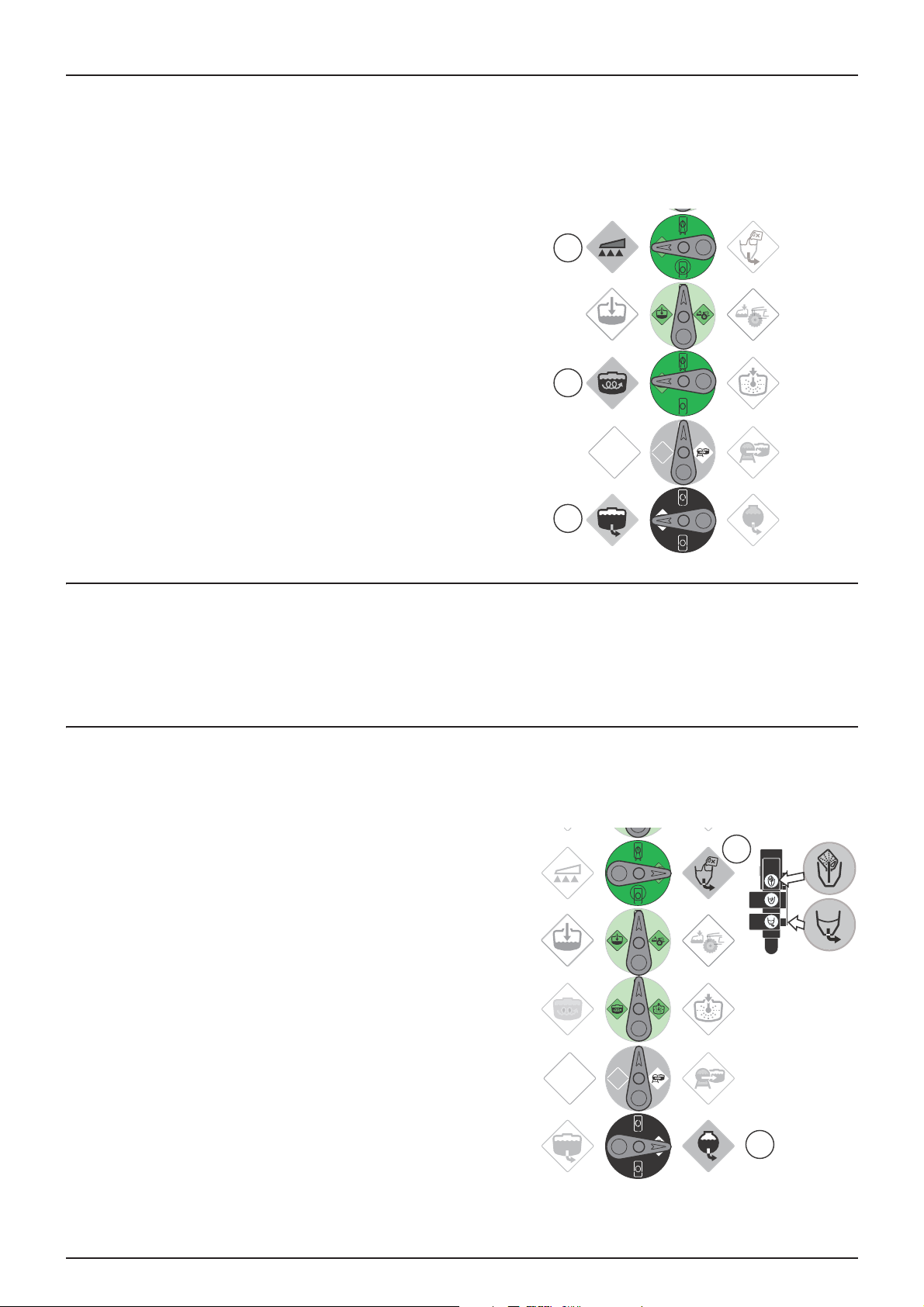
5 - Operation
DANGER! Turn the drum upside down over the rotating nozzle BEFORE you press the drum-rinse lever, so as to avoid
€
any mixture splashing on to the operator.
• Close the TurboFiller's suction valve after rinsing the hopper.
• Close the TurboFiller lid.
• When the mixture is uniform, turn the discharge valve handle (3)
to "Spray". Keep the power take-off running until you start to spray
the field in order to maintain thorough mixing - valve (2).
3
2
1
Adding powder products via the TurboFiller
• Fill the main tank half full with water (unless instructed otherwise by the product's manufacturer). See section "Filling
the main tank".
• Follow the same procedure as in section Adding liquid products via the TurboFiller page 45
Cleaning the TurboFiller
DANGER! Before pressing the TurboFiller rinsing valves, turn the drum over the rotating nozzle to avoid any risk of
±
being splashed by the mixture.
To rinse the TurboFiller, product packaging and drums, proceed as
follows:
• Set the suction valve (1) to "Rinsing tank" and the pressure valve (2)
to "TurboFiller"
The TurboFiller lid is open:
To clean empty packaging and drums:
2
• Turn the empty package or drum upside down over the rotating
rinsing nozzle in the middle of the hopper so as to cover it
completely.
• Press the "Drum rinse" valve and "suction O/C" simultaneously to
operate the rotating nozzle and empty the TurboFiller hopper of
rinsing liquid.
The TurboFiller lid is closed:
Use the "Drum rinse" valve to rinse the hopper after adding products to
the tank.
• Press the "Drum rinse" valve and "suction O/C" levers
simultaneously to operate the rotating nozzle and empty the TurboFiller hopper of rinsing liquid.
46
1
Page 47

5 - Operation
• Repeat this operation three times and then, after the final rinse, open the lid and check that the hopper is empty. If it
is not, close the lid and press the TurboFiller suction valve until it is completely empty.
IMPORTANT! Carefully clean the TurboFiller once the treatment is complete to ensure that it is clean before treating
other crops which could be sensitive to the products that have just been used. For more information, see section
Cleaning page 49"Cleaning".
Agitation prior to resuming treatment
If treatment has to be interrupted for a time, major or minor
sedimentation can occur. Before resuming treatment, the mix must be
homogenised.
1. Turn the suction valve (1) to "main tank". Turn the discharge valve
to "Spray" and the agitation valve to "Agitation". Close the other
valves.
2. Turn the suction valve (1) to "main tank". Turn valve (2) to
"Agitation" and the pressure valve (3) to "Spray". Close the other
valves.
3. Switch on the pump and set the power take-off to 540 rpm.
4. Allow agitation to continue for at least 10 minutes, or longer
depending on the mix.
3
2
1
47
Page 48

5 - Operation
Spray controls
1
7
TR2 V et Z
4
2
5
3
6
TR2 Y
1
8
• To stop the entire boom spraying, set the general O/C switch (3) to closed. The mixture then returns to the tank via the
pressure compensators. The anti-drip valves ensure the nozzles close instantly.
• To shut off one or more sections of the boom, set the corresponding switch(es) (7) to the closed position. The
compensators ensure that pressure is maintained in the sections that remain open.
• On the sprayer, the suction valve must be set to "In the main tank" and the discharge valve to "Spray". Then adjust the
agitation using the valve provided for this purpose.
7
4
2
5
3
6
8
For more information on the control units, refer to section TR2 Y version control unit page 23.
Quick guide - Operation
You will find below the correct position for the valves according to the desired operation.
1
2
3
4
48
Page 49

5 - Operation
Cleaning
General information
So that your sprayer gives you satisfaction for many years, carefully follow the programme of checks and maintenance below.
IMPORTANT! Read the various sections carefully. Before making a check or a repair, read the sections concerned
carefully. If you do not understand a point or if the work requires a tool which you do not have, for the sake of your
own safety, call your HARDI dealer.
IMPORTANT! A clean sprayer is a safe sprayer. A clean sprayer is ready for use. A clean sprayer will resist corrosion from
pesticides and their solvents.
IMPORTANT! Before you do any cleaning, also read the section on Filling/cleaning zone - Rules page 41
Recommendations
1. Read the instructions for the products you are using. Follow the instructions relating specifically to your protection,
neutralising agents, etc. Read the instructions on detergents and neutralising agents. If a cleaning procedure is
prescribed, follow it.
2. Comply with current legislation with regard to storage of pesticides, washing away residue, compulsory
decontamination, etc. If there is any doubt, seek advice from local bodies (the chamber of agriculture, for example).
3. Pesticides are usually rinsed away in a cleansing area. This is an area not used for crops. No flows or leaks of mixture
must be allowed to reach water courses, ditches, wells, springs, etc. Use a suitable cleaning area with a hard,
impenetrable surface (concrete), with drainage to a retention pond to avoid accidental contamination of the water
table. Rinsing water must be diluted and spread over a wider area to ensure it biodegrades. Always comply with current
legislation.
4. Cleaning starts with calibration, because if the amount of spray has been correctly calibrated, there will only be a small
amount of mix left in the tank at the end of spraying.
5. Get into the good habit of cleaning the sprayer immediately after use. It will be safe and ready for the next application.
And you will prolong the life of its components.
6. It is sometimes unavoidable that mix is left in the tank for a short time, overnight or while waiting for the weather to
improve. The sprayer should then be parked away from people and animals. See also Safety instructions page 37.
7. If you use corrosive products (liquid fertilisers, for example), protect all metal parts on the equipment with a rust
protection product before and after treatment.
IMPORTANT! To spray the rest of the diluted mix on the field that has just been treated, it is advisable to increase the
forward speed (go at twice the speed, if possible) and reduce the pressure to 1.5 bar.
IMPORTANT! If you clean the sprayer with a high-pressure sprayer, the equipment should be greased again all over.
49
Page 50
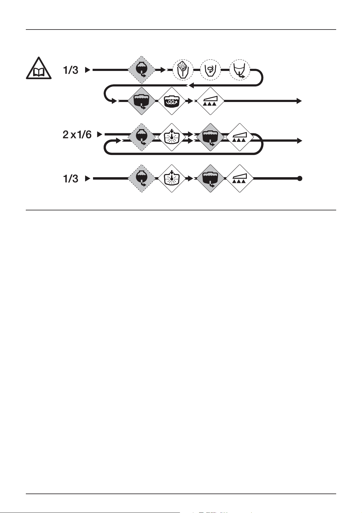
5 - Operation
Quick guide - Cleaning
You will find below the correct position for the valves according to the desired operation.
Cleaning the tank and the spraying system
1. Dilute the mix remaining in the tank with at least ten times its volume of water and spray it on the field you have just
sprayed.
2. Wear appropriate protective clothing. Choose a detergent suitable for the cleaning and neutralising agents,
if necessary.
3. Rinse and clean the outside of the sprayer and the tractor. Use a detergent if necessary.
4. Remove the suction filter and strainer from the tank and clean them. Be careful not to damage the mesh. Replace the
suction filter. Replace the filters after the sprayer has been completely cleaned.
5. Switch on the pump and rinse the inside of the main tank. Do not forget the top of the tank. Rinse and operate all the
components that came into contact with the mix. Before opening the boom sections to spray rinsing water, ensure
that it will flow away safely, either onto the field just treated or into a retention tank.
6. Once the tank is empty, stop the pump and fill it again to at least one fifth of its capacity with clean water.
Some products require the tank to be filled completely. Add a detergent and/or a neutralising agent, for example,
sodium carbonate or triple ammonia. Special detergents for sprayers are recommended, since some of them also
contribute to greasing ball valves, etc.
7. Engage the pump and operate all the controls that allow the liquid to rinse all the components. Keep the boom
sections until last. Some detergents and neutralising agents are more effective if they remain in the tank for a while.
Check the instructions for their use.
8. Drain the tank and allow the pump to run. Rinse the inside of the tank with the pump still running.
9. Switch off the pump. If the product used has a tendency to block filters and nozzles, remove them and clean them
immediately.
10. Put all filters and nozzles back in place and put the sprayer away. If you notice that the solvents are particularly
aggressive, leave the tank lid off.
IMPORTANT! To spray the rest of the diluted mix on the field that has just been treated, it is advisable to increase the
forward speed (go at twice the speed, if possible) and reduce the pressure to 1.5 bar (20psi).
IMPORTANT! If a cleaning procedure is recommended by the manufacturer of the product used, follow it exactly.
IMPORTANT! If you clean the sprayer with a high-pressure sprayer, the equipment should be greased again all over.
50
Page 51

5 - Operation
Cleaning and maintaining the filters
Clean filters ensure:
• that the sprayer's components such as valves, diaphragms and regulators will not be prevented from operating or
become damaged.
• that the nozzles will not become blocked during treatment.
• that the pump will last for a long time. A blocked suction filter will cause cavitation in the pump. The main filter that
protects the sprayer's components is the suction filter. Check it regularly.
Using the rinsing tank and the rotating nozzle.
The built-in rinsing tank can be used for two purposes:
IMPORTANT! If a cleaning procedure is recommended by the manufacturer of the product used, follow it exactly.
Diluting in the field before cleaning
Dilution in the field of the dead volume contained in the spraying system before cleaning the sprayer.
Cleaning the tank and the spraying system
1. Empty the tank as far as possible. Close the agitation valve and treat until the pump is no longer primed.
2. Turn the suction valve to "Rinsing tank" and the p ressure valve to "Spray".
3. Run the pump at approximately 300 rpm.
4. After transferring one third of the contents of the rinsing tank, turn the suction valve to "Main tank" and operate all the
valves on the pressure side in the following order, to rinse all the pipes and components:
• Turn the pressure valve to "Add products" to activate the ejector and open the suction valve on the TurboFiller.
• Open the Turbo deflector valve and close it as soon as clean water appears in the bottom of the hopper.
• Close the TurboFiller lid and press the package cleaning control trigger.
• Open the filler lid and check that the hopper is clean and empty.
• Once it is empty, close the filler's suction valve again. Check that the the external quick fill connector and pipe are clean.
5. Turn the suction valve to "Main tank" and the pressure valve to "Spray" and spray the contents of the tank on to the
field that has just been treated.
Rinsing the main tank:
6. Turn the suction valve to "Rinsing tank" and the pressure valve to "Clean inside of tank". Remove the tank strainer so as
not to impede cleaning behind it.
7. Transfer approximately one sixth of the contents of the rinsing tank and then turn the suction valve to "Main tank".
8. Turn the pressure valve to "Spray" and spray the contents of the tank on to the field that has just been treated.
9. Repeat points 6 to 8 once more.
WARNING! If you have used aggressive products (such as sulphonylurea) or if a cleaning additive is recommended,
±
carry out an additional cleaning cycle:
10. Fill the rinsing tank again.
11. Put 500 litres of clean water into the main tank. To fill the tank, see paragraph "Water filling device".
12. Add the cleaning additive via the product filler. Follow the instructions on the label on the additive.
13. Clean the whole spraying system again.
14. Do not forget to clean the strainers on the self-cleaning and suction filters with clean water.
15. Finally, rinse the sprayer with clean water.
IMPORTANT! The use of rotating nozzles does not guarantee that the main tank will be cleaned perfectly. Finish
cleaning with a broom, especially if the crops that you intend to treat next are sensitive to the product you have just
used.
51
Page 52

5 - Operation
Rinsing when the main tank is not empty
To rinse the pump, regulator, pipes, etc. in the event of an unforeseen stop to treatment before the tank is empty, e.g. sudden
rain.
Rinsing the spraying system:
1. Turn the suction valve to "Rinsing tank". (Leave the pressure valve in the "Spray" position).
2. Close the agitation valve.
3. Switch on the pump and spray the contents of the rinsing tank on to the field until the pipes/nozzles have been rinsed
with clean water.
4. Switch off the pump.
IMPORTANT! To spray the rest of the diluted mix on the field that has just been treated, it is advisable to increase the
forward speed (go at twice the speed, if possible) and reduce the pressure to 1.5 bar (20psi).
Cleaning the outside of the sprayer (optional)
A reel fitted with a 25 metre hose allows you to clean the outside of the sprayer. Before use, read the following
recommendations:
WARNING! Cleaning equipment operating under pressure. Incorrect use could cause personal injury.
±
DANGER! Wear appropriate footwear and protective glasses while working. During cleaning, protect yourself and all
€
persons present against splashes and spray.
DANGER! For your own safety and that of those around you, follow the instructions below.
€
Never direct the gun towards people, animals, electrical installations or any other object unable to withstand being
sprayed.
Do not try to clean clothes or boots while you or any other person is still wearing them.
1. Remove pin ref. 1 and turn the reel.
2. Use the gun (2) and unwind the hose to clean the sprayer.
1
2
3
52
Page 53

1. Turn the suction valve (1) to "Rinsing tank" and the pressure valve
(2) to "External washing gun".
2. Engage the spraying pump at idle and accelerate to obtain the
necessary pressure for washing the sprayer.
3. Squeeze the gun grip to clean the sprayer.
4. When the operation is complete, replace the gun in the position
provided.
5 - Operation
2
1
Boom purge (optional)
If you have purge valves at the ends of the boom, the cleaning procedure is as follows:
1. Rinse twice as per the normal cleaning procedure.
2. Open the purge valves.
3. Carry out a third rinse as per the cleaning procedure.
4. Close the purge valves.
WARNING! To prevent any contamination, the purge valves must only be opened during the final stage of cleaning.
±
Dead volume
A certain quantity of mixture inevitably remains in the system. It cannot be spread on the crop since the pump will end up
sucking air into the tank.
The dead volume is defined as the quantity of liquid in the system when the first clear pressure drop shows on the gauge.
The bottom of the tank must immediately be diluted with ten times its volume of clean water and sprayed on the field just
treated while increasing the forward speed. The pump, hitch and chassis may also be rinsed with water from the rinsing tank.
But you need to be sure that the mix contained in the pipes has no variation in concentration. It is therefore preferable to
have an untreated field on which to spray the dead volume.
53
Page 54

5 - Operation
Using the drain
The drain valve is accessible from the platform beside the tank lid.
Pull the cord to operate the drain. The valve is compressed by a spring
but can be held open by pulling the cord and then locking it in the V slot.
To close the drain, pull the cord down and the valve will close
automatically.
To transfer the contents of the tank to a reservoir, connect a pipe with a
quick connector to the drain valve.
54
Page 55

6 - Maintenance
C-50
Greasing
General information
Lubricants must be kept at a constant temperature, away from damp,
dust and condensation. Keep containers, funnels and other lubricators
clean; also, clean lubrication points before applying lubricants. Avoid
prolonged physical contact with lubricants.
Always follow quantity recommendations. Where no quantity is
indicated, fill the lubricator until it overflows.
The pictograms in the greasing diagrams show:
1. The lubricant to use (see "Recommended lubricants").
2. The greasing frequency in hours.
IMPORTANT! If you clean the sprayer with a high-pressure cleaner, the equipment should be completely re-greased.
Recommended lubricants
BEARINGS:
Universal lithium grease,
NLGI no. 2
Shell Retinax EP2
Castrol LMX
Power take-off lubrication points and frequency
Shaft series 100, PDF type
SLIDES AND SKIDS:
Lithium grease with
Molybdenum disulphide or
graphite
Shell Retinax HD 2 (or HDX 2)
LUBRICATION POINTS:
Total Transmission TM
SAE 80W/90
Castrol EPX 80W/90
Shell Spirax 80W/90
Mobil Mobilube 80W/90
55
Page 56
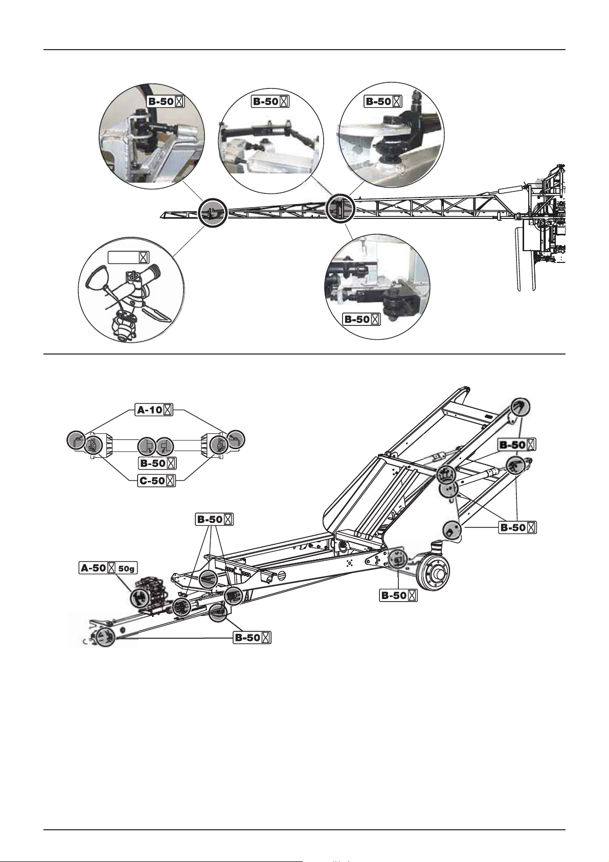
6 - Maintenance
Boom lubrication points and frequency
C-500
Chassis lubrication points and frequency
56
Page 57

6 - Maintenance
Maintenance cycle
Every 10 hours - Spraying system
Fill the tank with clean water, operate all the functions using a higher pressure than normal and check for leaks. Visually check
the spectrum of the jets at the exit from the nozzles, using clean water.
Every 10 hours - Nozzle filters
Check and clean.
Every 10 hours - Suction filter
Suction filter maintenance:
1. Remove pin (A).
2. Remove suction pipe connector (B) from its seating.
3. Filter (C) and its support are now accessible.
To re - a s semble :
4. Replace the support on the end of the filter.
5. Put the filter in position with the support facing upwards.
6. Check the condition of gasket (D) on the pipe connector and
grease it.
7. Re-fit suction pipe (B) and pin (A).
WARNING! Before you open the filter, put on gloves and
±
protective clothing.
Every 10 hours - Boom filters (optional)
If the boom is fitted with filters, unscrew the filter bowl, check the
strainer and clean it. Grease the gasket before re-assembling.
There are several mesh sizes available. Refer to the Technical
Specifications section - Filters and nozzles.
WARNING! Avoid splashing mixture when unscrewing the filter
±
bowl.
WARNING! Before you open the filter, put on gloves and
±
protective clothing.
57
Page 58

6 - Maintenance
Every 10 hours - Cyclone filter
To check the filter:
1. Close the suction and pressure valves.
2. Unscrew top (A).
3. Remove the top and strainer (B) from the body of the filter.
4. Remove the strainer from its built-in support in the top and
clean it.
To re - a s semble :
1. Grease the two gaskets in the top. Given the limited space,
it is easier to use a toothbrush.
2. Replace the strainer in its support (which should not be greased).
IMPORTANT! Do not put the strainer in its support the wrong way
round. If you do, it will not engage correctly.
3. Replace the assembly in the body of the filter and tighten the top all the way.
WARNING! Before you open the filter, put on gloves and protective clothing.
±
DANGER! The suction and pressure valves must always be closed before opening the Cyclone filter. Otherwise,
€
when opening the top, there is a risk of splashing or the main tank emptying.
Every 10 hours - Brakes (optional)
Press the brake pedal and check the operation of the sprayer's brakes.
Every 50 hours - Transmission shaft
Check the state and operation of the transmission shaft guards. Replace any defective part.
Every 50 hours - Tyre pressure
Check the tyre pressure against the table in the "Technical Specifications" section.
DANGER! Never inflate tyres to a pressure greater than that indicated in the table. There is a risk of over-inflated tyres
€
exploding and causing serious personal injury. See the section "Occasional maintenance - Replacing tyres".
WARNING! If you replace tyres, check that the new ones have the necessary load index.
±
Every 250 hours - Wheel nuts and bolts
Tighten studs and bolts to the following torque:
Hub studs on the wheel disc: 490 Nm.
Tightening order: Follow the numbering sequence in the illustration
opposite.
IMPORTANT! After fitting or tightening the wheels, put the plastic
covers back on the bolts.
58
Page 59

6 - Maintenance
Every 250 hours - Hydraulic system
Check the integrity of the system and make any necessary repairs.
WARNING! The boom lifting pipes should be replaced every 5 years.
±
Every 250 hours - Pipes and lines
Check the condition and attachment of all pipes and lines. Replace any damaged parts.
Every 250 hours - Boom adjustment
See "Occasional maintenance" section.
Every 250 hours - Hydraulic brakes (optional)
Apply full braking and check the condition and integrity of the entire brake line. Replace worn or defective parts.
If the hydraulic brake line was disassembled, the circuit must be re-primed:
1. Loosen the pipe on the two brake cylinders.
2. Apply the brakes until the oil comes out without air bubbles.
3. Tighten the pipe before releasing the brakes.
WARNING! The circuit must always be re-primed after dismantling the hydraulic brake line.
±
Every 250 hours - Parking brake check
Check the following points:
Parking brake lever: If you can pull it back further than 90° (to the
vertical), using a force of around 25kg, then the cable is too long and
should be shortened.
Parking brake cable: It should be slack when the brake is released.
If this is not the case, it should be lengthened.
Correct length: Brake released, the cable should be stiff but not taut.
The length of the cable is adjusted by turning the nut inside the chassis.
Condition of the brake cable (wear or damage). Replace all worn or
damaged parts.
59
Page 60
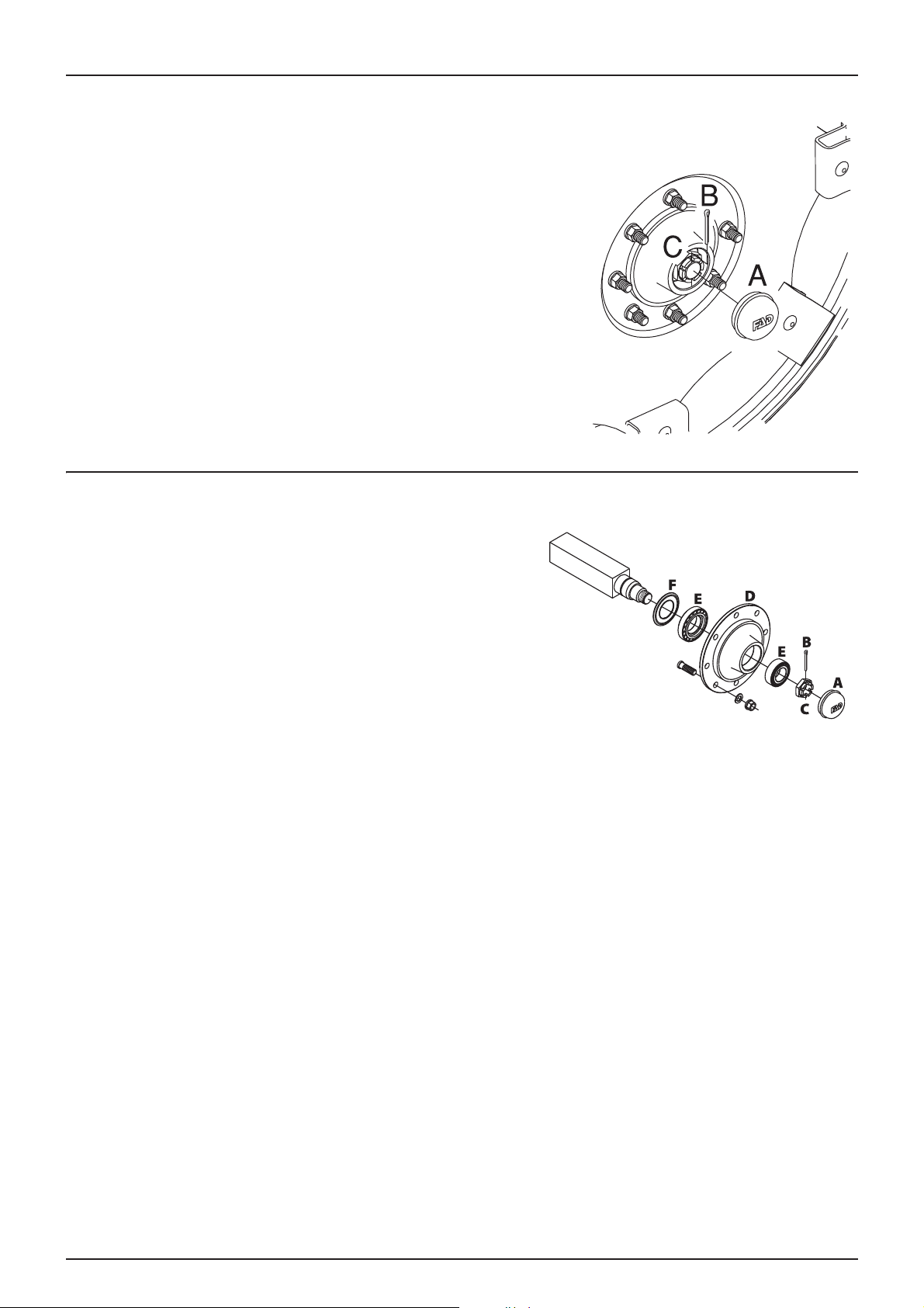
6 - Maintenance
Every 250 hours - Wheel bearings
Check the play in the wheel bearings:
1. Put chocks in front of and behind the left wheel and raise the right
hand wheel.
2. Shake the right hand wheel to check the play in the bearings.
3. If there is play, chock under the axle to prevent the sprayer falling
off the jack.
4. Remove hub cap (A) and pin (B). Turn the wheel and tighten shaft
nut (C) until slight resistance is felt in the rotation of the wheel.
5. Loosen the shaft nut until the first notch (horizontal or vertical) is
aligned with the hole for the pin in the shaft.
6. Insert a new pin and bend it.
7. Replace the hub cap.
8. Do the same for the left hand wheel.
Every 1,000 hours - Wheel bearings (unbraked)
Check the condition of the bearings, as follows:
1. Put chocks in front of and behind the left wheel and raise the right
hand wheel.
2. Place stands under the axle.
3. Remove the wheel.
4. Undo the six Allen screws and remove hub cap (A), pin (B) and
shaft nut (C).
5. Remove hub (D). Use a hub extractor if necessary.
6. Remove bearings (E), clean them with a degreasing product and
then dry.
7. Check for wear and discolouration of the ball bearings; replace them if they are in poor condition.
8. Re-fit hub (D) and bearings (E) using a new gasket (F).
9. Grease hub (D) and bearings (E) before fitting them on the shaft.
10. Fit shaft nut (C). Turn hub (D) and tighten nut (C) until slight resistance is felt.
11. Loosen shaft nut (C) again until the first notch is aligned with the hole for the pin in the shaft.
12. Insert new pin (B) and bend it.
13. Re-fit hub cap (A) on hub (D). Slightly tighten the six Allen screws.
14. Re-fit the wheel and tighten the nuts. See "Every 50 hours" for the tightening torques and order. Start by tightening all
the bolts to half the indicated torque and then to the full torque.
15. Tighten again after ten hours of use. Check the torque every day until it stabilises.
IMPORTANT! The shaft has a vertical hole and a horizontal hole for the pin. Use the first hole that aligns with the notch
when you loosen the shaft nut.
WARNING! If you do not feel sufficiently competent to change the wheel bearings, contact your HARDI EVRARD
±
dealer.
60
Page 61
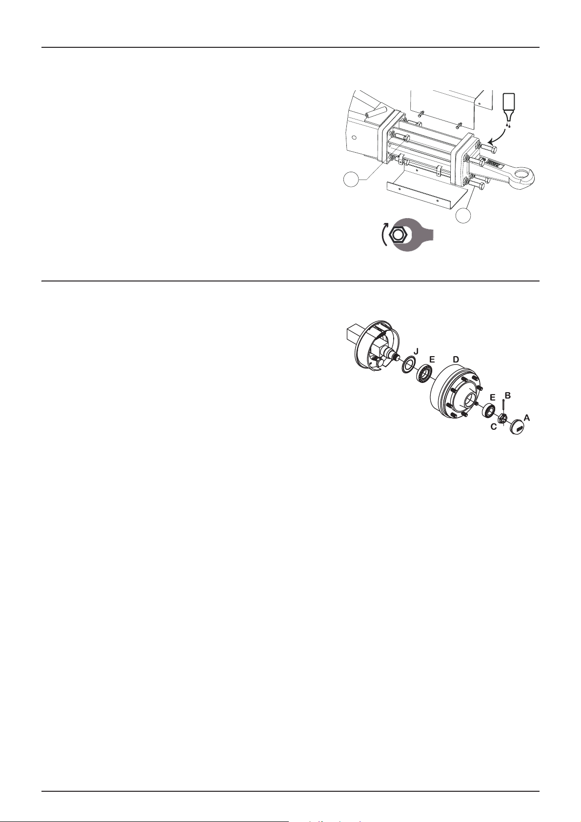
Every 1,000 hours - Hitch extension
1
1
Check the tightening of the fixing screws on the extension and hitch ring.
Apply the tightening torque indicated.
€
The screws are secured in place with High strength Thread-
±
locking fluid.
Every 1,000 hours - Wheel bearings and brakes
Check the condition of the bearings and wearing parts on brakes as
follows:
6 - Maintenance
232 N.m
232 N.m
frein
filet
FORT
1. Put chocks in front of and behind the left wheel and raise the right
hand wheel.
2. Place stands under the axle.
3. Remove the wheel.
4. Undo the six Allen screws and remove hub cap (A), pin (B) and
shaft nut (C).
5. Remove the hub and the drum. Use a hub extractor if necessary.
6. Clean drum (D) with a vacuum cleaner or rinse with water.
7. Rinse the remaining parts of the axle frame with water and dry them.
8. Remove bearings (E), clean them with a degreasing product and dry them.
9. Check the diameter of the drum and thickness of the linings - replace them if they are worn.
Max. permitted wear on components:
Max. diameter of drum: 302mm (30.1998cm)
Min. thickness of linings: 2.0mm (2.00000mm)
DANGER! The dust released by brakes is harmful. Avoid inhaling brake dust. Wear a mask when doing maintenance
€
work on brakes. Do not clean brakes with an air compressor. Use a vacuum cleaner or rinse them with water to avoid
spreading dust.
WARNING! The minimum thickness indicated is the absolute minimum and must not be exceeded. Replace linings if
±
you think that they will not last until the next check.
WARNING! If you replace linings or drums, you must do so for both wheels.
±
IM POR TAN T! I f th e drum ha s to be se par ated from the hub, a hydr aul ic p ress sh oul d be used to remo ve the st uds fro m
the wheels.
WARNING! Avoid getting oil, grease or copper paste on linings and drums.
±
61
Page 62

6 - Maintenance
IMPORTANT! The shaft has a vertical hole and a horizontal hole for the pin. Use the first hole that aligns with the notch
when you loosen the shaft nut.
WARNING! If you do not feel sufficiently competent to carry out these operations, contact your HARDI dealer.
±
10. Remove the pin between the air diaphragm cylinder and the cam
shaft.
11. Remove key (G), nut (F) and fixing bolt (H) from the brake shoe and
slide the shoe over the cam. Twist the pair of shoes to remove the
return springs (I). Replace the shoes if the linings are worn.
12. Apply a small quantity of copper paste to the moving parts and
re-fit the shoes and return springs.
13. Re-fit the shoes with the fixing bolt. Then separate the shoes and
slide them over the cam. Tighten the locknut on the fixing bolt and
insert a new key.
14. Check for wear and discolouration of the ball bearings; replace
them if they are in poor condition.
15. Fit the hub and bearings using a new gasket.
16. Grease the hub and bearings before fitting them on the shaft.
17. Fit the shaft nut. Turn the hub and tighten the nut until slight
resistance is felt.
18. Loosen the shaft nut until the first notch is aligned with the hole for the pin in the shaft.
19. Insert a new pin and bend it.
20. Replace the hub cap. Slightly tighten the six Allen screws.
21. Adjust the brakes as indicated in "Every 250 hours".
22. Re-fit the wheel and tighten the nuts. See "Every 50 hours" for the tightening torques and order. Start by tightening all
the bolts to half the indicated torque and then to the full torque.
23. Tighten again after ten hours of use. Check the torque every day until it stabilises.
62
Page 63

6 - Maintenance
4
5
2
3
B
1
2A
2A
Occasional maintenance
General information
The maintenance/replacement intervals for the following parts depend greatly on the conditions of use to which the
sprayer is subjected and it is therefore not possible to be precise.
Replacing pump valves and diaphragms
Pump model 363:
Repair sets for diaphragm pumps are available (valves, gaskets,
diaphragms, etc.). Check the pump model - the reference for the
HARDI EVRARD set is:
Model 363: part no. 75073700
Val ves
Remove cover (1) to replace valves (2) - note their orientation for
re-fitting them correctly.
IMPORTANT! A special valve with a white mechanism (2A) must
be fitted to the two upper intakes. Position them as illustrated.
All the other valves have a black mechanism. It is recommended
that new gaskets (3) are used for re-assembly.
Diaphragms
Remove bolt (4). Diaphragm (5) is now accessible. If the crankshaft
housing is wet, dry it and then grease the pump well. Also check that the
drain hole under the pump is not blocked. Re-fit the parts, applying the
tightening torques below.
Tightening torques for 363 pumps :
Diaphragm bolt (4): 90 Nm/66.6 lb/ft
Diaphragm cover bolts: 90 Nm/66.6 lb/ft
IMPORTANT! Before tightening the four bolts in the diaphragm cover (B), position the diaphragm between the middle
and the top in order to get a perfect seal between the pump housing and the diaphragm cover. Turn the crankshaft
if necessary.
63
Page 64

6 - Maintenance
5
1
2
2
3
4
6
4
Checking/replacing the regulation valve piston
If you do not obtain sufficient pressure, or if it is not stable, replace the
piston and the ball.
1. Remove the four screws (2) and the housing.
2. Remove the four screws (B).
3. Replace ball (3) and gasket (4).
4. Loosen nut (5), remove and replace piston (6).
5. Re-assemble all the parts in reverse order.
Checking/replacing valve gaskets on EVC valves
Check the sealing on distribution valves regularly. Run the sprayer, using
clean water and open all the distribution valves. Remove pin (A) carefully
and remove return pipe (B). Once the seat is drained, there should no
longer be any return flow.
If it leaks, change gasket (E).
1. Remove pin (C).
2. Release the distribution valve from its seat.
3. Undo screw (D) and replace gasket (E).
4. Re-assemble all the parts in reverse order.
Adjusting the gauge
Check the gauge reading regularly. When the tank is empty, the float
should sit on pin (D) in the steel tube with the ring at the top on line (A).
If this is not the case, remove cap (B), loosen screw (C) and adjust the
length of the steel cable.
64
Page 65

6 - Maintenance
Replacing the steel cable on the gauge
To replace the cable, the float tube should be removed from the tank:
1. Remove the drain valve (see paragraph "Replacing the drain valve gasket") and loosen the connector that holds the
tube in position.
2. Pull the tube through the hole in the drain valve until it is clear of the top of the tank.
3. Now remove it from the tank via the manhole.
DANGER! Do not attempt to enter the tank. The parts are accessible from the outside.
€
Replacing the drain valve gasket
If the drain valve on the main tank leaks, replace the gasket and the seat
as shown.
DANGER! Do not attempt to enter the tank. The parts are
€
accessible from the outside.
WARNING! When removing the drain valve, wear a mask or
±
protective glasses.
1. Check that the tank is empty and clean.
2. The valve must be closed and the cord loose.
3. Remove pin (A) and pull housing (B) downwards. All the valve's
parts are now accessible.
4. Check the condition of the cord and valve assembly (C), replace
gasket (D) and re-assemble.
5. When re-assembling, replace seat (E). Grease gasket (F) before replacing it.
6. Replace pin (A).
IMPORTANT! Check that the drain valve works correctly, using clean water, before putting chemicals into the tank.
Adjusting the 3-way valves
You can adjust the MANIFOLD valve if it is too difficult to turn, or
conversely, too loose (= risk of it leaking). The ideal adjustment is to be
able to turn it slowly with one hand. Use the proper tool and turn the
toothed washer inside the valve, as shown.
65
Page 66

6 - Maintenance
Spray lines and connectors
Poor sealing is often due to:
• Missing gaskets or rings
• Damaged or poorly fitted gaskets
• Dry or misshapen gaskets or rings
• Impurities.
In the event of a leak:
DO NOT OVER-TIGHTEN Disassemble the pipes and check the position
and condition of the gaskets and rings. Clean, grease and re-assemble.
Gaskets must be greased over their WHOLE CIRCUMFERENCE before
re-assembly. Use a non-mineral lubricant.
For ELBOW connectors, use can use pliers. STRAIGHT connectors should
only be tightened by hand.
Replacing the transmission shaft guards
Refer to the manufacturer's user manual.
Replacing the transmission shaft journal crosses
Refer to the manufacturer's user manual.
Replacing bulbs
1. Switch off the headlights.
2. Undo the screws of the headlights and remove the cover or optic.
3. Remove the bulb.
4. Insert a new bulb, replace the cover and re-secure the screws.
Replacing the boom lights bulbs (optional)
IMPORTANT! Some lamps (boom lights) contain halogens, which means that they must not be handled directly with
the fingers, as this may damage them.
When handling halogen (H7) bulbs, always use a clean, dry cloth.
Ensure that the lamp has cooled completely and that the power to it has
been cut, so as to avoid any risk of burning when replacing it.
• Carefully pull the lugs off the bulb.
• Remove screw ref. 1 and pull back clip ref. 2.
• Take out lamp ref. 3 and replace it (halogen H7 type).
1
3
66
2
Page 67
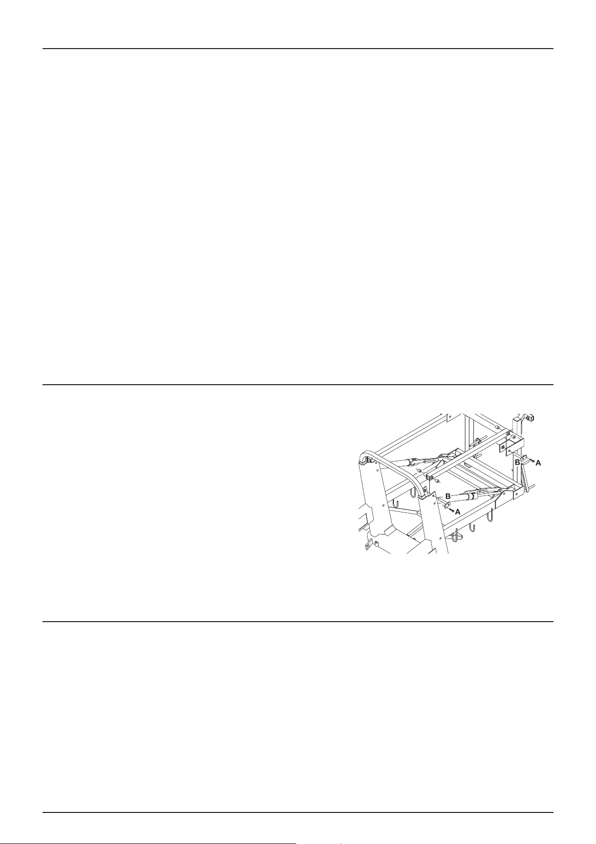
6 - Maintenance
Replacing tyres
To replace tyres, preferably contact a specialist and follow the recommendations below.
1. Clean and check the rims before fitting.
2. Check that the diameters of the rims correspond exactly with those of the tyres.
3. Check the condition of the insides of the tyres. Make any possible repairs before fitting the inner tubes. Never re-use
defective tyres.
4. Clean the inside of the tyres before fitting the inner tubes.
5. Before fitting, grease the edges of the tyres and the rim flanges with a lubricant or anti-corrosion product. Never use a
petroleum based lubricant which could damage the tyres. With the appropriate lubricant, a tyre will never slip on the
rim.
6. When fitting, use suitable tools recommended by the tyre manufacturer.
7. Check that the tyre is centred and that its edges fit perfectly against the rim. Otherwise there is a risk of tearing the
edge of the tyre.
8. Never inflate a tyre beyond its recommended pressure. Refer to section Tyre specifications page 78
9. Never put inner tubes inside tubeless tyres.
DANGER! Failure to follow tyre fitting recommendations resulting in the poor fitting of tyres on rims could cause the
€
tyre to burst with a risk of personal, or even fatal injury.
DANGER! Never use damaged tyres or rims. The use of damaged, broken, deformed or re-welded rims is strictly
€
prohibited.
Replacing wear rings on the lifting frame
Check wear rings regularly and replace them before they wear through.
1. Hitch the sprayer to the tractor and unfold the boom to the
working position.
2. Lift the central section of the boom using appropriate lifting
equipment and hold it so that the arms of the parallelogram are no
longer supporting the load
3. Remove screws (A) and pins (B) on one of the upper arms of the
parallelogram, then replace the worn rings.
4. Re-fit the arm.
5. Proceed similarly for the other upper arm.
6. The lower arms will be dismounted at the same time.
7. Grease all greasing connectors.
8. Remove the lifting equipment.
Replacing wear rings on the trailing hitch
If you notice too much play in the pins, the wear rings should be replaced. Contact your HARDI EVRARD dealer.
67
Page 68

6 - Maintenance
Operating the safety valve
To ensure that the spraying circuit operates correctly over time, the safety valve should be operated regularly.
This prevents any blockage and ensures that the safety valve is operating correctly. To do this, turn the pressurevalve to
"Transfer" or to an unused function while the pump is running. This is good practice with any sprayer and particularly for
those without optional accessories.
DANGER! Before setting the pressure valve to "Transfer", it is very important to check that the transfer connector plug
€
is fully screwed in and completely closed. Failure to do this will result in a risk of contamination and injury, if the plug
should shoot out when the system is pressurised. If it is not possible to close the plug completely, grease the seal and
not the screw. The suction and pressure valves must always be closed before opening the Cyclone filter. Otherwise,
when opening the top, there is a risk of splashing or the main tank emptying.
68
Page 69

Adjusting the boom - general information
1. Before carrying out the adjustment, check the following points:
2. The sprayer must be correctly lubricated (see section "Greasing").
3. Hitch the sprayer to the tractor.
4. Both the tractor and sprayer must be on an even surface.
5. Unfold the boom.
6. Set the boom tilting to the neutral position.
IMPORTANT! For boom terminology voir The terminology for dual-fold booms is as follows page 20.
The cylinders should be adjusted with no pressure in the hydraulic system.
÷
WARNING! No one should stand under the boom during the various adjustment operations.
±
Anti-yaw device
If the boom whips (forward and backward horizontal movements),
the whip damper should be adjusted. To do this:
• Slightly tighten nuts (1) to increase the spring pressure on the
friction pads (2).
1
6 - Maintenance
2
• Check the friction pads regularly and replace them if they are worn.
Excessively tightening the anti-yaw device can reduce its
÷
effectiveness.
Central frame locking device
The central frame is locked by two cylinders, one either side of it. To adjust the locking device, the boom must be unfolded
and the sprayer parked on a horizontal surface.
• Unlock the central frame (the cylinder rod is in)
• Loosen locknut (1) and screw the foot (2) all the way.
• Lock the central frame by operating the control. The cylinder rods
are all the way out.
• Unscrew the feet and, using your hands, support them on the
shims (3).
• Re-tighten locknut (1)
1
2
3
To prevent any damage to the locking device, the feet should press against the shims only moderately.
69
Page 70

6 - Maintenance
1
2
Horizontally aligning the inner arms with the central frame
This adjustment consists of positioning the boom arms horizontally.
The sprayer must be on even ground and the boom unfolded.
• Position the central frame horizontally, using a spirit level.
• Unscrew locknut (1)
• Adjust the length of the damping device (2) until the boom is
horizontal. Use a spirit level if necessary.
1
2
For the best adjustment, it is preferable for the ends of the boom
÷
to point slightly upwards
Adjusting the height of the boom on the transport supports
This consists of adjusting the height of the boom in relation to the transport supports. Check the distance between the top
of the transport supports and the boom. If it is less than 50mm, the boom arms should be adjusted.
• Position the central frame horizontally.
• Check the dimension: d = 40mm
• Lift the central frame fully and fold the boom.
• Loosen the locknuts and adjust the length of the rod (1) until the
distance between the transport supports and the boom is not less
than 50mm.
d
1
• Re-tighten the locknuts.
Adjusting the boom open/close
This adjustment consists of aligning the boom in relation to the central frame.
• Loosen the locknut (1).
• Turn the cylinder rod to align the boom arms.
• Re-tighten the locknut.
It is preferable for the end of the boom to point slightly forwards.
÷
Alignment of the end of the boom (1) with the central frame (2).
2
1
70
Page 71

6 - Maintenance
Winter storage
Storage procedure
To preserve its components, ensure their longevity and protect your sprayer, follow the procedure below.
Before storage
When the treatment season is over, devote a little time to your sprayer. Residues of phyto-pharmaceutical products
encourage the equipment's components to deteriorate.
1. Clean the sprayer completely - inside and out - as described in Cleaning the outside of the sprayer (optional) page 52
Check that all lines, valves, pipes and other components have been washed with detergent and then rinsed with clean
water, so that no residue remains.
2. Replace damaged gaskets and repair any leaks.
3. Drain the equipment completely and leave the pump running for a few minutes. Operate all valves, handles and levers,
in order to drain the spraying system as much as possible. Allow the pump to run until there is only air coming out of
the nozzles. Do not forget to drain the rinsing tank as well.
4. Pour approximately 50 litres of anti-freeze solution into the tank (one third anti-freeze, two thirds water).
5. Run the pump and operate all valves and equipment, such as the regulator, product filler, etc., so that the solution
spreads throughout the system. Open the general O/C valve and all the distribution valves until the solution reaches
the nozzles. The anti-freeze also prevents gaskets, rings and diaphragms from drying out.
6. Lubricate all lubrication points as indicated in the "Greasing" section, without paying any attention to greasing
frequencies.
7. When the equipment is completely dry, remove any traces of rust and touch up paintwork as necessary.
8. Drain, take off and store pressure gauges vertically, away from frost.
9. Apply a fine coat of anti-corrosion oil (Shell Ensis Fluid, Castrol Rustillo, or equivalent) to all metal parts. Avoid getting
oil on rubber parts, pipes and tyres.
10. Fold the boom into the transport position and bleed out the pressure from all hydraulic functions.
11. Store electrical plugs and sockets in a plastic bag to protect them from damp and dust.
12. Remove control units from the tractor cab and store them in a frost-free place, so that they keep clean and dry.
An environment free from condensation is recommended.
13. Clean hydraulic connectors and put protective caps on them.
14. Grease all cylinder rods that are not fully in, so as to protect them from corrosion.
15. Isolate the wheels from the ground to protect them from damp and prevent the tyres from deforming. You can apply
black wax to the walls of tyres to protect the rubber.
16. Drain any condensation from the air brake reservoir.
17. You can cover the sprayer with a tarpaulin to protect it from dust. Remember to allow air to circulate, so as to prevent
condensation.
After storage
After over-wintering, the equipment must be prepared for the new campaign in the following way:
1. Remove the tarpaulin.
2. Remove the support from under the axle if there is one and check the tyre pressures.
3. Wipe the grease from the cylinder rods.
4. Fit the pressure gauges. Use Teflon tape to make the seal.
5. Hitch the sprayer to the tractor and make the electrical and hydraulic connections.
6. Check all electrical and hydraulic functions.
7. Drain any remaining anti-freeze from the tank.
8. Rinse the whole of the spraying circuit with clean water.
71
Page 72

6 - Maintenance
9. Fill the tank with clean water and check all functions.
10. Check the operation of the brakes. Do not forget that the effectiveness of the brakes is reduced until any rust formed
on the drums has been eliminated. Never brake hard, until the drums are clean.
72
Page 73

7 - Fault finding
Operating incidents
General information
Operating incidents are often due to the same causes:
1. Even a small suction leak will reduce the flow from the pump and can completely stop suction.
2. A blocked suction filter can impede suction or stop it and prevent the pump from operating normally.
3. A blocked pressure filter causes an increase in pressure upstream of the filter This can trip the safety valve.
4. Blocked boom filters or nozzle filters cause the pressure to increase at the gauge but fall in the boom.
5. Impurities sucked in by the pump can prevent valves from closing correctly. This reduces the flow from the pump.
6. Incorrect re-assembly of the pump, in particular the diaphragm covers, causes air to be drawn in or leaks, and reduces
the flow from the pump.
7. Oxidised or dusty hydraulic components result in poor connections and premature wear.
8. A poor power supply causes operating errors or breakdowns in the electrical circuit.
To prevent such inconveniences, ALWAYS check that:
1. The suction, pressure and nozzle filters are clean.
2. Pipes, particularly the suction pipes, are intact: no leaks, no kinks, no pinching.
3. Rings and gaskets are in position and in good condition.
4. The pressure gauge is operating correctly. Dosage accuracy depends on it.
5. Regulation is working correctly. Carry out checks using clean water.
6. Hydraulic components are clean.
7. The tractor's battery is in good condition and the contacts are clean.
73
Page 74

7 - Fault finding
Spraying system
FAULT PROBABLE CAUSE VERIFICATION/SOLUTION
No spray reaching the boom. Air being taken in on the suction side. Check that the seal on the suction filter is airtight.
Check the connection and condition of the suction
pipe.
Check the tightening of the pump diaphragms and
cylinder heads.
Air in the system. Put water in the suction pipe to prime it.
Suction/pressure filters blocked. Clean the filters.
Check that the yellow suction pipe is not blocked or
positioned too close to the bottom of the tank.
Lack of pressure Incorrect assembly. "Turbo" valve open.
Yellow suction tube too close to the bottom of the
tank.
Pump valves blocked or worn. Check for obstructions and the state of wear.
Defective pressure gauge. Check for a blockage at the pressure gauge inlet.
Drop in pressure Blocked filters. Clean all the filters. Use cleaner water. If the product is
a powder, switch on agitation.
Worn nozzles. Check the flow and replace the nozzles if there is a
Airtight tank. Check that the tank cover vent is free.
Air being sucked in at the end of the tank. Reduce pump rotation.
Increase in pressure. Pressure filters becoming blocked. Clean all the filters.
Formation of foam. Air being taken into the system. Check that all suction connectors (gaskets and rings)
Excessive agitation. Reduce pump rotation.
Leak at the bottom of the pump. Damaged diaphragm. Replace it. See "Replacing diaphragms and valves".
Regulator does not work or only poorly. Blown fuse(s). Check the mechanical operation of switches. Use a
Incorrect polarity. Brown positive (+). Blue negative (-).
Control valves do not close correctly. Check the cleanliness of the valves and seats.
No supply. Incorrect polarity. Check that brown is positive (+).
discrepancy in excess of 10%.
are airtight.
Check the sealing of the safety valve.
Check returns to the tank.
Use an anti-foaming additive.
contact aerosol in the event of oxidation.
Check the motor. 450-500 mA max., otherwise replace
the motor.
Check the position of the micro-switch plate. Loosen
the retaining screws half a turn.
Blue negative (-).
Check the printed circuit board for loose solder joints
or connections.
Check the contact between the fuse and the fuse
carrier.
74
Page 75

7 - Fault finding
Hydraulic functions - Z boom
FAULT PROBABLE CAUSE VERIFICATION/SOLUTION
No hydraulic response from the boom. Insufficient hydraulic pressure. Check the oil pressure.
Check the tractor's hydraulic oil level.
Insufficient oil flow. The flow must be at least 25l/min., with a max. of
130l/min.
Check the tractor's hydraulic oil level.
Blown fuse(s). Check/replace the connection box fuse.
Oxidised/poorly connected electrical plugs. Check/clean all connections, plugs, etc.
Insufficient supply. The electro valves require at least 8 volts.
Use at least 4mm cables for the power supply.
Defective relays/diodes in the connection box. Check relays, diodes and solder joints on the printed
circuit board in the connection box. LEDs indicate the
operation of the boom.
Blocked restrictors a or b in the bypass block. Disassemble and clean restrictors a and b (see
hydraulic system diagram). Replace hydraulic oil and
filter.
Incorrect polarity. Check polarity. Red positive (+), Black negative (-).
The boom rises to the max. when the tractor control
valves are under pressure.
The oil is heated in closed centre systems. Bypass valve 0 does not close properly. Check/close (screw) valve 0.
A cylinder is not working. Blocked restrictor. Disassemble and clean the restrictor.
Poor flow of oil into the hydraulic block. Reverse the direction of the hydraulic feed in the pipes
or reverse the direction of the tractor valve lever.
Return pressure greater than 20 bar. Connect the free return to the tractor's oil reservoir.
Split the return in two and route each one to the
reservoir via two valves.
Internal leak in the flow regulator. Replace regulator gaskets and contact washers.
Replace the regulator.
75
Page 76

7 - Fault finding
Mechanical problems
Backup operation - Spraying system
In the event of a power supply failure, all functions may be controlled manually. First, disconnect the multi-pin plug from the
control unit. Then turn the emergency butterfly screw by hand.
The breakdown may be the result of a blown fuse. A spare fuse can be found in the box. Fuse type: Thermo.
76
Page 77

8 - Technical specifications
A
B
Dimensions
General information
All weights, values and dimensions depend on the sprayer's equipment and specific settings.
Overall dimensions
Sprayer A - Overall length, mm A - Overall height, mm
2500 TR2 5,130 or 6,450 3,060 to 3,330
Overall width: 2,370 or 2,550mm
Weight
The weights indicated should be understood as referring to a sprayer equipped with a TurboFiller and hydraulic brakes.
The weights with a full tank apply to a 2,500 litre spray tank and a 260 litre rinsing tank.
Ranger TR2:
Empty tank
Boom width Load on axle Load on hitch Total weight
24m 1,960 350 2,310
Weights are expressed in kilograms (kg)
Conversion factors, SI units into imperial
All units used in this manual are from the International System. Sometimes, imperial units are used. Use the following factors
to convert SI units into imperial units:
SI units Imperial units Factor
Weight kg lb x 2.205
Surface hectares acres x 2.471
Length cm inch x 0.394
m ft x 3.281
m yd x 1.094
km mile x 0.621
Speed kph mph x 0.621
kph m/s x 0.277
Volume/hectare l/hectare gal/acre x 0.089
Volume ml fl. oz x 0.0352
l Imp. pt. x 0.568
l gal x 0.22
Pressure bar lb/inv (psi) x 14.504
Temperature °C °F (°C x 1.8) + 32
Power kW hp x 1.341
Torque Nm lb ft x 0.74
77
Page 78

8 - Technical specifications
Specifications
Pump model 363/10.0
Temperature and pressure ranges
Spraying system:
Working temperature: 2°C to 40°C (36°F to 104°F)
Safety valve tripping pressure: 15 bar (220psi)
Max. discharge valve pressure: 20 bar (290psi)
Max. suction valve pressure: 7 bar (100psi)
Hydraulic system:
Max. working temperature: 75°C (167°F)
Hydraulic system working pressure:
Tractor: 210 bar (3,046psi)
min. 160 bar (2,321psi)
Filters and nozzles
Mesh dimensions
30 mesh: 0.58mm
50 mesh: 0.30mm
80 mesh: 0.18mm
100 mesh: 0.15mm
Reservoir specifications
Spraying tank capacity 2,500 litres
Rinsing tank capacity 260 litres
Hand wash tank capacity 20 litres
Tyre specifications
Tyre dimensions Recommended inflation pressure Min. load index A8/A2
270/95R38 TL 3.6 bar 138A8/138B
270/95R48 TL 3.6 bar 142A8/142B
300/95R46 TL 3.6 bar 146A8/146B
340/85R48 TL 2.4 bar 152A8/149B
420/85R38 TL 4.0 bar 144A8/141B
78
Page 79

8 - Technical specifications
Raw materials and recycling
Disposing of the sprayer
When the sprayer reaches the end of its life, it should be cleaned carefully. The tanks, pipes and connectors, made of
synthetic material, may be burned in an incinerator. Metal parts may be sent to a scrap yard. Always comply with current
legislation on waste.
Raw materials used:
Tanks: High density polyethylene
Chassis etc.: Steel
Boom: Aluminium, Steel
Pump: Cast iron
Diaphragms: PUR
Pipes (suction): PVC
Pipes (discharge): EPDM
Valves: Glass-reinforced polyamide
Filters: Polypropylene
Nozzles: Free polyoxymethylene
Connectors: Glass-reinforced polyamide
79
Page 80

8 - Technical specifications
Spraying system schematic diagrams
Basic spraying system
16
4
19
14
6
1. main tank
2. rinsing tank
12
11
13
10
26
25
3
24
1
22
4
5
23
6
8
6
9
2
6
7
20
6
21
14. discharge MANIFOLD valves
15.
3. rinsing nozzle
4. pressure gauge
5. EVC valves
6. non-return valve
7. rinsing tank filling connector
8. TurboFiller
9. TurboFiller valves
10. Cyclone filter
11. suction filter
12. spraying pump
13. suction MANIFOLD valves
16. regulation valve
17.
18.
19. safety valve
20. boom filters
21. spraying sections
22. agitation
23. Drain valve
24. main tank return
25. external filling connector
26. transfer connector
80
Page 81

Spraying system with options
16
4
17
19
6
14
26
8 - Technical specifications
15
3
24
11
12
1. main tank
2. rinsing tank
3. rinsing nozzle
4. pressure gauge
5. EVC valves
13
10
25
1
22
4
5
23
18
6
8
6
9
2
6
7
20
6
21
14. discharge MANIFOLD valves
15. gun for external cleaning equipment (optional)
16. regulation valve
17. Tank bottom dilution valve - Discharge
18. Tank bottom dilution valve - Suction
6. non-return valve
7. rinsing tank filling connector
8. TurboFiller
9. TurboFiller valves
10. Cyclone filter
11. suction filter
12. spraying pump
13. suction MANIFOLD valves
19. safety valve
20. boom filters
21. spraying sections
22. agitation
23. Drain valve
24. main tank return
25. external filling connector
26. transfer connector
81
Page 82

8 - Technical specifications
Electrical connections
Road signalling
Wiring complies with Standard ISO 1724.
Position Wire colour
1. Left indicator Yellow
2. Free Blue
3. Chassis White
4. Right indicator Green
5. Rear right position light Brown
6. Brake lights Red
7. Rear left position light Black
Spray II unit electrical connections
37 or 39-pin plug with cable.
39 pins 37 pins Spray II
1a 5 S1+
1b 6 S11c 26 Left end nozzle
2a 7 S2+
2b 8 S22c 25 Right end nozzle
3a 9 S3+
3b 10 S33c 29 +12V sensor
4a 11 S4+
4b 12 344c 4 PWM 1TX
5a 14 S5+
5b 15 S55c 27 Earth
6a 16 S6+
6b 17 S66c 13 Option 5 regulation valve
7a 18 S7+
7b 19 S77c 33 Option 1 4-20mA
8a 37 S8+
8b 36 S88c 32 Option 2 Frq
9a 35 S9+/Air orientation 0-5V
9b 34 S9-/Turbine speed 0-5V
9c free Option 3/Tank gauge
10a 21 O/C+
10b 22 O/C10c free Output option PWM
11a 23 Pressure+
11b 24 Pressure11c 28 Flow
12a 20 Foam plugs 0-5V
12b 1 Option 4 Rx
12c 31 Speed
13a 3 TM L
13b 2 TM R
13c 30 Sensor (ground)
82
Page 83

8 - Technical specifications
EVC operating unit
The EVC electrical adjustment meets European standards for noise reduction.
When connecting optional equipment, the maximum current for each contact is 2 Amps. For the unit overall, the total
current should not exceed 10 Amps.
HC 2500/HC 5500 Function + Signal -
Opt 1 Pressure sensor Brown Blue Opt 2 Rotation sensor Brown Blue Black
Speed Speed sensor Brown Blue Black
Flow Flow meter Brown Blue Black
L end nozzle Left end nozzle Brown Blue
R end nozzle Right end nozzle Brown Blue
Reg Regulation valve Brown Blue
Bypass EVC O/C Brown Blue
Sec 9 option B x x
Sec 8 Boom lights x x
Sec 7 Brown White
Sec 6 Yellow Grey
Sec 5 Brown Blue
Sec 4 Brown Blue
Sec 3 Brown Blue
Sec 2 Brown Blue
Sec 1 Brown Blue
Gnd Earth Left Right - +
Foam marker Not used Black Brown Red Orange
83
Page 84

8 - Technical specifications
SELECTEUR N°2
SELECTEUR N°1
BLOCAGE
DEVERS
BRAS EXTERIEUR
DROIT
BRAS EXTERIEUR
GAUCHE
BRAS NTERIEUR
DROIT
BRAS INTERIEUR
GAUCHE
MONTEE / DESCENTE
VANNE
ISOLEMENT
TR2 Y version diagrams
Hydraulic system principle, version TR2 Y
H
y
d
r
a
u
li
c
s
y
s
t
e
m
f
o
r
Y
b
o
o
m
84
Page 85

TR2 Y version diagrams
Hydraulic system for Y boom
Dépliage / Repliage
de la rampe
8 - Technical specifications
Montée / descente
Correction du dévers
Dépliage / Repliage
de la rampe
Blocage cadre central
85
Page 86

8 - Technical specifications
Electrical diagram for blockage - tilt - boom unfolding selection - TR2 Y
VERINS DE BLOCAGE
VERS VERINS DE
DEPLIAGE REPLIAGE
DE LA RAMPE
VERIN DE DEVERS
SELECTEUR N°2
NOIR
SELECTEUR N°1
BRUN
BLEU
-
NOIR
ROUGE
+
86
PLOT PUISSANCE
12VDC
Page 87

Index
Index
A
Adding liquid products via the TurboFiller 45
Adding powder products via the TurboFiller 46
Adding products through the opening in the tank 45
Agitation prior to resuming treatment 47
Agroparts 89
B
Before use 25
Boom and terminology 20
Boom filters 57
Boom pressure gauge 22
Boom, adjustment 69
C
CE identification plate 15
Chassis 13
CIGARETTE LIGHTER 34
Cleaning the filters
51
Cleaning the TurboFiller 46
Connecting the transmission shaft 27
Control unit supports 34
Conversion factors 77
Cyclone filter 17, 58
D
Declaration of Conformity 7
Diluting in the field 51
Disposal 79
Drain valve 65
Driving on the road 13, 15
Drum rinsing control 19
E
Electrical connections
Electrical supply 34
Emergency operation 76
EVC adjustment 17
EVC electrical adjustment 83
EVC operating unit 83
EVC spraying system with optional accessories 17
EVC valve 64
External cleaning 52
External cleaning equipment 23
F
Filling the main tank 41
Filling via the opening in the tank 42
Filling/cleaning zone 41
Filters 17
G
Gasket 65
Gauge 64, 65
General information 73, 77
General view 14
82
H
Hose reel
23
Hydraulic boom system 85
Hydraulic system 75
I
Identification plates 15
J
JOBCOM SOCKET 34
L
Leaks
73
Lifting the sprayer with a jack 25
M
Main tank gauge 22
Modifying the track width 30
N
Nozzle filters 57
O
Open centre hydraulic block 33
Operator qualification 10
P
Personal protection
44
Platform 21
Power required 34
Pressure compensation 36
Pressure valve 16
Protective equipment 44
Pump 16
Q
Quick guide 48
R
Recommendations
10
Reference no. 15
Regulation 17
Regulation valve 64
Required tractor control valves 33
Rinsing product drums 19
Rinsing, main tank not empty 52
Road signalling 82
S
Safety instructions 37, 44
SelfSteer drawbar 21, 29
Spare parts 89
Speed sensor 35
Spray gun 23
Spray lines 66
Spraying control unit 23, 24
Spraying system 57, 74, 76
Step 21
Storage 71
Storage box 22
Suction filter 57, 73
Suction valve 17
Support leg 26
87
Page 88

Index
T
Tank
13
Tanks 13
Temperature and pressure ranges 78
Transmission shaft 27
TurboFiller 18
TurboFiller suction valve 18
U
Unloading the sprayer
Use of electrical EVC adjustment 36
User safety 27
Using the sprayer 10, 13
V
Valves
16
Valves and pictograms 16
W
Water filling device 43
Widths when half folded 20
Working pressure 78
25
88
Page 89

Spare parts
For all information on spare parts, go to the www.agroparts.com
website. Information is available free of charge, once you have registered
your details on the home page.
Page 90

HARDI INTERNATIONAL A/S
Helgeshøj Allé 38 - DK 2630 Taastrup - DENMARK
 Loading...