

NAVIGATOR
3000/4000/5000/6000
Instruction book
67028104-102 Version1.02
GB - 05.2016
www.hardi.com.au

We congratulate you for choosing a HARDI plant protection product. The reliability and
efficiency of this product depend upon your care. The first step is to carefully read and pay
attention to this instruction book. It contains essential information for the efficient use and
long life of this quality product.
The original instruction book is approved and published in English. All other languages are translations of the
original. In the event of any conflicts, inaccuracies or deviations between the English original and other languages
the English version shall prevail.
Illustrations, technical information and data in this book are to the best of our belief correct at the time of printing.
As it is HARDI AUSTRALIA policy permanently to improve our products, we reserve the right to make changes in
design, features, accessories, specifications and maintenance instructions at any time and without notice.
HARDI AUSTRALIA is without any obligation in relation to implements purchased before or after such changes.
HARD AUSTRALIA cannot undertake any responsibility for possible omissions or inaccuracies in this publication,
although everything possible has been done to make it complete and correct.
As this instruction book covers more models and features or equipment, which are available in certain countries
only, please pay attention to paragraphs dealing with precisely your model.
Published and printed by HARDI AUSTRALIA
μ
This book covers updated NAVIGATOR 3000 - 6000 litre models.

Table of Contents
1
Table of Contents
2 - Safety notes
Operator safety .....................................................................................................................................5
Symbols ........................................................................................................................................................................................................................ 5
Precautions ................................................................................................................................................................................................................ 5
Beware of overhead power lines! ............................................................................................................................................................... 6
Spray Drift! .................................................................................................................................................................................................................. 6
Service ........................................................................................................................................................................................................................... 6
Chemical Safety ....................................................................................................................................................................................................... 7
Label explanation .................................................................................................................................................................................................. 8
3 - Description
General Info .........................................................................................................................................11
View ............................................................................................................................................................................................................................. 11
View ............................................................................................................................................................................................................................. 12
Identification plate ............................................................................................................................................................................................. 13
Road worthiness .................................................................................................................................................................................................. 13
Sprayer Use ............................................................................................................................................................................................................. 13
Frame .......................................................................................................................................................................................................................... 13
Tanks and Equipment ...................................................................................................................................................................................... 13
Liquid System ......................................................................................................................................14
Pump .......................................................................................................................................................................................................................... 14
Valves and Symbols ........................................................................................................................................................................................... 14
RinseTank ................................................................................................................................................................................................................. 15
DynamicFluid4 Pressure Regulation ....................................................................................................................................................... 16
EasyClean Filter ..................................................................................................................................................................................................... 18
CycloneFilter .......................................................................................................................................................................................................... 19
Chem Filler options ............................................................................................................................................................................................ 20
HARDI®VACnMIX (optional equipment) ............................................................................................................................................... 20
Control Manifold VACnMIX ........................................................................................................................................................................... 21
HARDI®TURBO FILLER (optional equipment) ..................................................................................................................................... 22
Clean Water Tank ................................................................................................................................................................................................ 23
DilutionKit (optional) ......................................................................................................................................................................................... 23
BoomPrime (optional) ...................................................................................................................................................................................... 24
Diagram - Basic Liquid System ................................................................................................................................................................... 25
Diagram - Liquid System with Options and TurboFiller) ............................................................................................................ 26
Diagram - Liquid System with Options and VACnMIX ............................................................................................................... 27
Hydraulic Systems ...............................................................................................................................28
Hydraulic Blocks ................................................................................................................................................................................................... 28
Boom ...................................................................................................................................................30
Boom configuration, terminology and Operators Manual ....................................................................................................... 30
Equipment ...........................................................................................................................................32
Platform ..................................................................................................................................................................................................................... 32
Right Side Cover .................................................................................................................................................................................................. 32
Tank Level Indicator ........................................................................................................................................................................................... 32
Nozzle Pressure Gauge .................................................................................................................................................................................... 33
ChemLocker (optional) .................................................................................................................................................................................... 33
SafetyLocker ........................................................................................................................................................................................................... 33
4 - Sprayer setup
General info .........................................................................................................................................35
Before Putting the Sprayer into Operation ......................................................................................................................................... 35
Support Leg ............................................................................................................................................................................................................ 35
Jack Up the Sprayer ........................................................................................................................................................................................... 35
Hose Package Support .................................................................................................................................................................................... 36
Transmission Shaft ..............................................................................................................................37
Operator Safety .................................................................................................................................................................................................... 37
PTO Installation ..................................................................................................................................................................................................... 37
Hydraulic Systems ...............................................................................................................................38
General Info ............................................................................................................................................................................................................ 38

Table of Contents
2
Requirements for tractor ................................................................................................................................................................................ 38
Open Centre Hydraulics (optional) .......................................................................................................................................................... 39
Electrical Connections .........................................................................................................................40
Power Supply ......................................................................................................................................................................................................... 40
Installation of Control Unit Brackets ........................................................................................................................................................ 41
Road Safety Kit (optional) ............................................................................................................................................................................... 41
Speed Transducer for Sprayer ..................................................................................................................................................................... 42
Liquid System ......................................................................................................................................43
CycloneFilter .......................................................................................................................................................................................................... 43
BoomPrime Adjustment (optional) ......................................................................................................................................................... 44
Transport .............................................................................................................................................45
Transport lock Eagle/TR4 boom ................................................................................................................................................................ 45
Transport lock boom FTZ, B3 ....................................................................................................................................................................... 45
Track width, axles and wheels .............................................................................................................46
Altering the Track Gauge (optional) ........................................................................................................................................................ 46
Counter Weight .................................................................................................................................................................................................... 47
Brakes ..................................................................................................................................................48
Hydraulically Activated Brakes (optional) ............................................................................................................................................. 48
........................................................................................................................................................................................................................................ 48
5 - Operation
General Info .........................................................................................................................................49
Environmental Info ............................................................................................................................................................................................ 49
Boom ...................................................................................................................................................50
Safety Info ................................................................................................................................................................................................................ 50
Manoeuvring of the boom Y-version (only EAGLE Boom) ........................................................................................................ 50
Manoeuvring of the boom (Z-version) with HC 5500 .................................................................................................................. 51
Manoeuvring of the Boom (Z-version) with HC 6500 / HC 8500 / HC 9500 / ISOBUS ............................................. 52
Hydraulic Slanting Control (Optional) .................................................................................................................................................... 53
Boom Tilt Function (Z-version only) ........................................................................................................................................................ 53
Alternative boom width ................................................................................................................................................................................. 53
Liquid System ......................................................................................................................................54
Filling/Washing Location Requirements .............................................................................................................................................. 54
Filling of Water ...................................................................................................................................................................................................... 54
Filling Through Tank Lid ................................................................................................................................................................................. 55
External Filling Device (optional) ............................................................................................................................................................... 55
Filtered Fast Fill System ................................................................................................................................................................................... 56
Banjo Filtered Fast Fill System ..................................................................................................................................................................... 57
Filling of Rinsing Tank ....................................................................................................................................................................................... 58
Filling of Clean Water Tank ............................................................................................................................................................................ 58
Safety Precautions - Crop Protection Chemicals ............................................................................................................................. 59
Filling Chemicals through Tank Lid ......................................................................................................................................................... 59
Chemical Filling by VACnMIX (optional) ............................................................................................................................................... 60
Filling the VACnMIX with water ................................................................................................................................................................. 60
Filling with liquid or granular chemicals by VACnMIX (optional equipment) .............................................................. 61
Filling chemicals by VACnMIXs Chem Probe ..................................................................................................................................... 62
VACnMIX Rinsing ................................................................................................................................................................................................. 63
Filling Liquid Chemicals by using HARDI TurboFiller .................................................................................................................... 64
Filling Powder Chemicals by using HARDI TurboFiller ................................................................................................................ 65
Agitation before Resuming a Spray Job ............................................................................................................................................... 66
Operating the control unit while spraying (Z-version) HC 5500 ........................................................................................... 67
Operating the control units while spraying (Z-version) HC 6500 / HC 8500 / HC9500 / ISOBUS ..................... 68
Quick reference - Operation ......................................................................................................................................................................... 69
TurboFiller Rinsing .............................................................................................................................................................................................. 70
BoomPrime (optional) ...................................................................................................................................................................................... 70
Cleaning ...............................................................................................................................................71
General Info ............................................................................................................................................................................................................ 71
Quick Reference - Cleaning .......................................................................................................................................................................... 72
Standard Cleaning .............................................................................................................................................................................................. 72

Table of Contents
3
Cleaning the Tank and Liquid System ................................................................................................................................................... 73
Cleaning and Maintenance of Filters ...................................................................................................................................................... 73
Use of Rinsing Tank and Rinsing Nozzles (Optional) ..................................................................................................................... 74
Technical Residue .............................................................................................................................................................................................. 75
Using the Drain Valve ....................................................................................................................................................................................... 75
6 - Maintenance
Lubrication ..........................................................................................................................................77
General Info ............................................................................................................................................................................................................ 77
Recommended lubricants ............................................................................................................................................................................. 77
Boom and Centre lubrication ...................................................................................................................................................................... 77
Trailer/ParaLift Lubrication & Oiling Plan .............................................................................................................................................. 77
PTO Lubrication & Oiling Plan ..................................................................................................................................................................... 78
Service and Maintenance Intervals .....................................................................................................79
Boom and Centre ................................................................................................................................................................................................ 79
After first use .......................................................................................................................................................................................................... 79
10 Hours Service - EasyClean Filter .......................................................................................................................................................... 79
10 Hours Service - CycloneFilter ................................................................................................................................................................ 80
10 Hours Service - In-Line Filter (optional) .......................................................................................................................................... 80
10 Hours Service - Spraying Circuit .......................................................................................................................................................... 81
10 Hours Service - Brakes (optional) ........................................................................................................................................................ 81
50 Hours Service - Transmission Shaft ................................................................................................................................................... 81
50 Hours Service - Wheel Nuts ................................................................................................................................................................... 81
50 Hours Service - Tyre Pressure ................................................................................................................................................................ 81
250 Hours Service - Readjustment of the Boom ............................................................................................................................. 81
250 Hours Service - Hydraulic Circuit ...................................................................................................................................................... 81
250 Hours Service - Hoses and Tubes .................................................................................................................................................... 81
250 Hours Service - Wheel Bearings ........................................................................................................................................................ 82
250 Hours Service - Brake Adjustment (optional) ........................................................................................................................... 82
250 Hours Service - Hydraulic Brakes (optional) .............................................................................................................................. 82
1000 Hours Service - Wheel Bearings (No Brakes) .......................................................................................................................... 83
1000 Hours Service - Wheel Bearings and Brakes ........................................................................................................................... 83
Occasional Maintenance ......................................................................................................................85
Pump Valves and Diaphragms Renewal ............................................................................................................................................... 85
Cone check/renewal for pressure regulation valve ....................................................................................................................... 86
Cone check/renewal for EVC distribution valve .............................................................................................................................. 86
Level Indicator Adjustment .......................................................................................................................................................................... 86
Level Indicator Cord Renewal ..................................................................................................................................................................... 87
Drain Valve Seal Replacement .................................................................................................................................................................... 87
Nozzle Tubes and Fittings ............................................................................................................................................................................. 87
Adjustment of 3-Way Valve .......................................................................................................................................................................... 88
Retighten the Frame ......................................................................................................................................................................................... 88
Change of Bulbs ................................................................................................................................................................................................... 88
Wear Bushing Renewal on Steering ........................................................................................................................................................ 88
Suspension Rubber Dampers (optional) .............................................................................................................................................. 89
Shield Replacement on Transmission Shaft ......................................................................................
................................................. 89
Replacement of Transmission Shaft Cross Journals ...................................................................................................................... 89
Change of Tyres ................................................................................................................................................................................................... 89
Safety Valve Activation .................................................................................................................................................................................... 90
Off-Season Storage ..............................................................................................................................91
Off-Season Storage Program ....................................................................................................................................................................... 91
7 - Fault finding
Operational Problems .........................................................................................................................95
General Info ............................................................................................................................................................................................................ 95
Liquid System ........................................................................................................................................................................................................ 96
Hydraulic System, Y-boom version .......................................................................................................................................................... 97
Hydraulic System, Z-boom version .......................................................................................................................................................... 97
IntelliTrack ................................................................................................................................................................................................................ 98

Table of Contents
4
Mechanical problems ..........................................................................................................................99
Emergency Operation - Hydraulics .......................................................................................................................................................... 99
Emergency Operation - Liquid system .................................................................................................................................................. 99
8 - Technical specifications
Dimensions ....................................................................................................................................... 101
General Info ..........................................................................................................................................................................................................101
Overall Dimensions ..........................................................................................................................................................................................101
Weight .....................................................................................................................................................................................................................102
Pump Specifications ......................................................................................................................... 103
Pump Model 363/5.5 ......................................................................................................................................................................................103
Pump Model 363/10.0 ...................................................................................................................................................................................103
Pump Model 463/5.5 ......................................................................................................................................................................................103
Pump Model 463/6.5 ......................................................................................................................................................................................103
Pump Model 463/10.0 ...................................................................................................................................................................................103
Pump Model 463/12.0 ...................................................................................................................................................................................104
Filters and Nozzles ............................................................................................................................................................................................104
Temperature and Pressure Ranges ........................................................................................................................................................104
Brakes ........................................................................................................................................................................................................................105
Airborne Noise Emission ...............................................................................................................................................................................105
Tyre Pressure ........................................................................................................................................................................................................106
Materials and Recycling .................................................................................................................... 107
Disposal of the Sprayer ..................................................................................................................................................................................107
Electrical ConnectionsElectrical Connections for SPRAY II ............................................................... 108
Rear Lights .............................................................................................................................................................................................................108
Index
Index ................................................................................................................................................. 109

5
2 - Safety notes
Operator safety
Introduction
This manual contains safety information which could prevent crop damage, personal injury or death. It is compulsory that all
operators intending to use this equipment read and understand this manual and related literature. Safety information in each
section must be read carefully, and if any doubt remains contact your HARDI dealer for further information.
Symbols
These symbols are used thorough the book to designate where some sort of extra attention has to paid for the reader. The
four symbols have following meaning.
€
This symbol means DANGER. Be very alert as your safety is involved!
±
This symbol means WARNING. Be alert as your safety can be involved!
μ
This symbol means ATTENTION. This guides to better, easier and more safe operation of your sprayer!
÷
This symbol means NOTE.
Precautions
Note the following recommended precautions and safe operating practices before using the sprayer.
General info
€
Read and understand this instruction book before using the equipment. It is equally important that other operators
of this equipment read and understand this book.
If any portion of this instruction book remains unclear after reading it, contact your HARDI dealer for further
explanation before using the equipment.
€
Local law may demand that the operator is certified to use spray equipment. Adhere to the law.
€
Tractor drivers seat is the intended working place during operation.
€
Wear protective clothing. Clothing may differ depending on chemical being sprayed. Adhere to the local law.
Wash and change clothes after spraying. Wash tools if they have become contaminated.
€
Do not eat, drink or smoke while spraying or working with contaminated equipment.
In case of poisoning, immediately seek medical advice. Remember to identify chemicals used.
Filling and spraying
€
No persons are allowed in the operations area of the sprayer. Be carefull not to hit people or surroundings when
manoeuvring the sprayer, especially when reversing.
€
Slow down when driving in uneven terrain as the machine might be in risk of turning over.
€
Keep children away from the equipment!
€
Do not attempt to enter the tank.
€
Do not go under any part of the sprayer unless it is secured. The boom is secure when placed in the transport
brackets.

2 - Safety notes
6
Beware of overhead power lines!
€
Operating agricultural machinery near power-lines presents a potentially fatal hazard. It is the responsibility of the
operator to ensure that minimum safe clearances are strictly observed, in particular when transporting the
implement, spraying, raising, tilting or lowering the boom. Also be aware that during hot or windy weather sagging
or swaying of
power lines can reduce safe working clearances.
Power line structures and voltages can vary in different regions of Australia, so it is vitally important to consult your local
Electricity Supply Authority for details of minimum safe clearances in your area before proceeding.
A: Minimum safe clearance from conductor for vehicles and implements.
B: Minimum safe clearance from conductor for persons and livestock.
Spray Drift!
±
Serious crop damage can occur as a result of spray drift. Certain climatic conditions can increase the risk of spray drift
onto neighboring crops.
±
Although calibration information is provided in the Spraying Techniques Manual it is vitally important that you read the
chemical manufacturer’s recommendations for the correct use of their product. The manufacturers label will also state the
products limitations and warnings.
Wind speed, temperature, humidity and chemical properties should all be considered when determining if conditions are
suitable for spraying. Contact your local Department of Primary Industries for details of relevant publications explaining the risks
and how best to minimise them. It is the responsibility of the sprayer operator to ensure that the spraying conditions are suitable
for the application of the chemical to be used
±
Warning: After changing chemicals or crops it is essential that the entire sprayer be flushed. This includes
disconnecting hoses from the filters and pressure relief valve and cleaning residue and sediment in the hoses, valves
and filters. Failure to do so may potentially lead to serious crop damage
Service
€
Pressure test with clean water prior to filling with chemicals. Never dismount the hoses if the machine is in operation.
DANGER! Do not exceed the P.T.O. max. recommended r.p.m.
€
Rinse and wash equipment after use and before servicing.
€
Never service or repair the equipment while it is operating. Always replace all safety devices or shields immediately
after servicing.
€
Disconnect electrical power before servicing and depressurize equipment after use and before servicing.
€
If an arc welder is used on the equipment or anything connected to the equipment, disconnect power leads before
welding. Remove all inflammable or explosive material from the area.
€
The External Cleaning Device should not be used if important parts of the equipment have been damaged, including
safety devices, high pressure hoses, etc.
2 - Safety notes
7
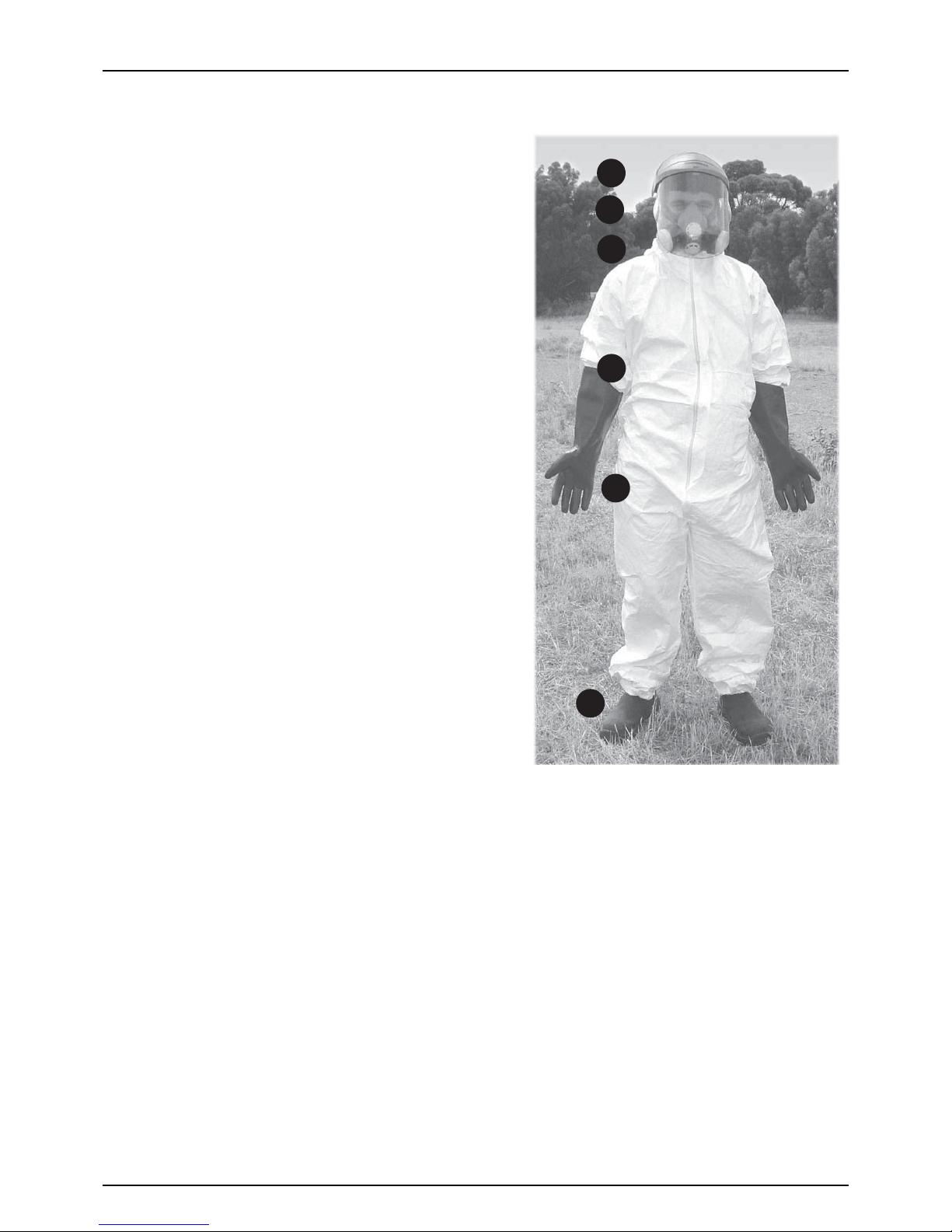
Chemical Safety
€
Danger: Chemical contamination poses a serious health risk.
It is the
responsibility of the operator to ensure safe work practice is
observed and correct safety equipment and clothing is used.
Safety equipment
Depending on the type of chemical used, some or all of the following
protective clothing and equipment will be required (see diagram to
right).
1. Headgear
2. Safety goggles or face shield
3. Respirator
4. Chemical resistant coveralls
5. Chemical resistant gloves
6. Chemical resistant boots.
Contaminated clothing and equipment
Contaminated clothing should be carefully removed, safely isolated
and then appropriately laundered or disposed of, taking care not to
contaminate the inside of the tractor cab. Tools and equipment used
must also be safely isolated and carefully washed and decontaminated.
Australian Safety Standards
Protective clothing and equipment must conform to Australian Safety
Standards and must always be used when handling chemicals,
operating the sprayer and during the cleaning and decontamination
process.
Chemical Information
Always read the chemical manufacturer’s labels as they contain critical
information about your safety and the environment. Always consider
the environment when disposing of chemical residue (see section on
decontamination). Chemical labels are registered by the National
Registration Authority. Laws vary from state to state regarding the
purpose for which a chemical may be used so consult your local authorities.
€
Danger: Agricultural chemicals can be dangerous. Always read chemical labels and carefully follow safety
recommendations to the letter.
μ
Attention: Please refer to the chapter on “Cleaning and Decontamination” in the Operation section of this manual for
further information.
Disposal of chemical containers
Please note that in addition to normal safe operating practices, and in the interests of a cleaner and safer environment HARDI
Australia supports the “drumMUSTER” chemical drum recycling program:
• Rinse empty drums immediately after use.
• Puncture metal drums through the base from the inside.
• Remove lids to allow drums to dry completely.
• Recycle with “drumMUSTER”
For more information please visit: www.drummaster.com.au or call 1800008707
±
Warning: Used chemical containers pose a severe threat to persons, animals and the environment. Before disposal,
contact
the Environmental Protection Authority or the Department of Primary Industries in your area for more information.
1
2
3
4
5
6
2 - Safety notes
8
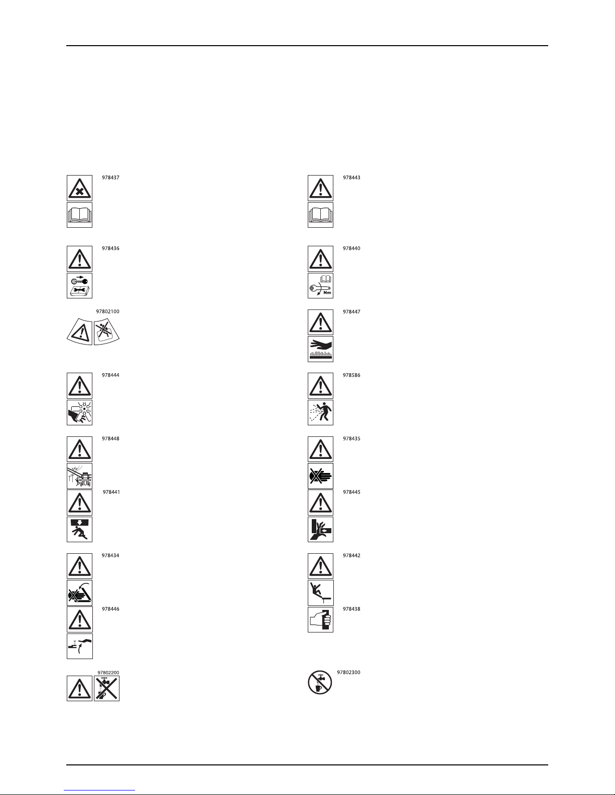
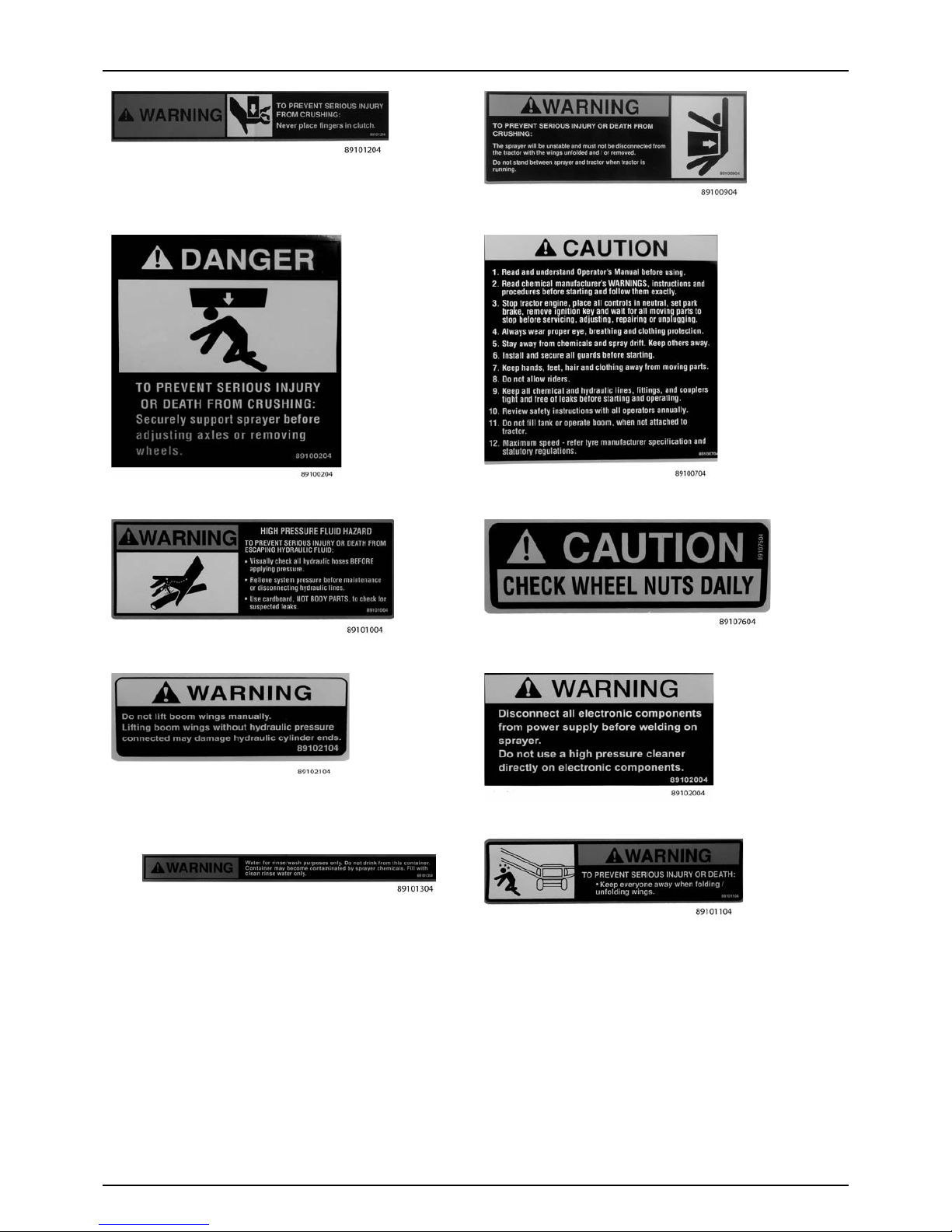
Label explanation
The labels are designating potential dangerous places on the machine. Anybody working with or being in close range of
the sprayer must respect these labels!
The labels should always be clean and readable! Worn or damaged labels must be replaced with new ones. Contact your
local dealer for new labels.
÷
Note that not all labels shown here will apply to your sprayer.
Chemical handling!
Carefully read the informations about
chemical preparation before handling the
machine. Observe instructions and safety
rules when operating.
Service!
Carefully read operators instruction book
before handling the machine. Observe
instructions and safety rules when operating.
Service!
Shut off the engine and remove ignition key
before performing maintenance or repair.
Service!
Tighten to torque according to instruction
book.
Risk of death!
Do not attempt to enter tank.
Risk of burn!
Stay clear of hot surfaces.
Risk of injury!
Do not open or remove safety shields while
engine is running.
Risk of injury!
Flying objects, keep safe distance from
machine as long as the engine is running.
Risk of injury!
Keep sufficient distance away from electrical
power.
Risk of injury!
Keep hands away.
Risk of squeeze!
Stay clear of raised unsecured loads.
Risk of squeeze!
Never reach into the crushing danger area as
long as parts are moving.
Risk of squeeze!
Keep hands away, when parts is moving.
Risk of falling off!
Do not ride on platform or ladder.
Risk of sprayer tipping over!
Be aware when disconnecting the sprayer.
Grip area!
Manual handling of boom etc.
Not for drinking!
This water must never be used for drinking
water.
Not for drinking!
This water must never be used for drinking
water.
2 - Safety notes
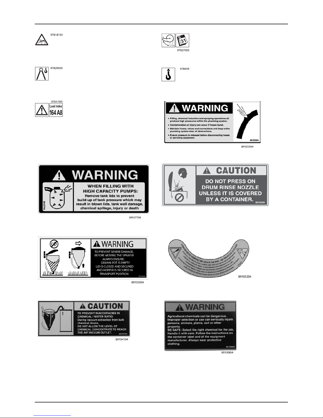
9
Tank under p ressure!
Beware when moving lid.
EasyClean filter service!
Open and clean filter monthly.
Lifting point! Lifting point!
Load index!
Max. permitted load rating is 164 at 40 km/h.
2 - Safety notes
10
11
3 - Description
General Info
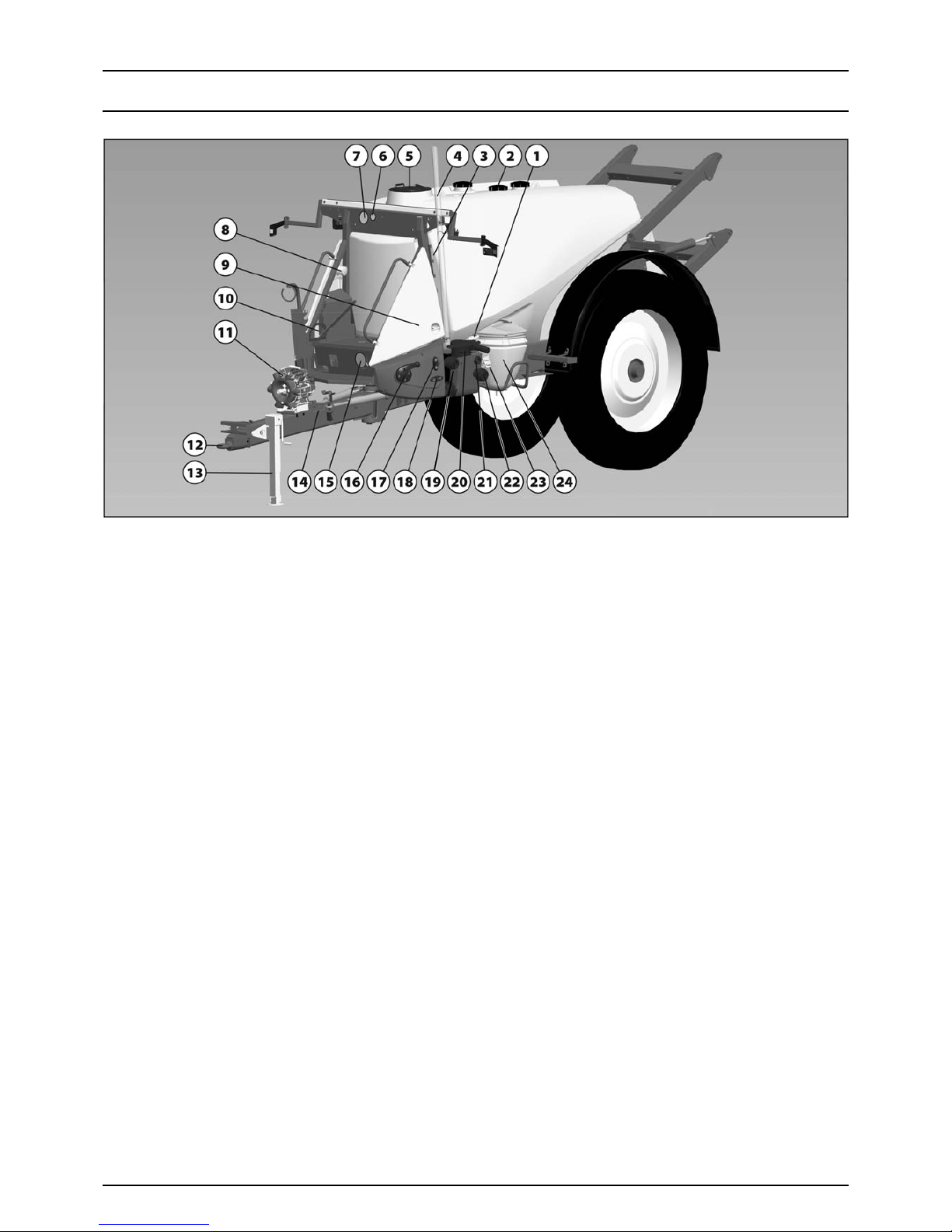
View
1. EcoFill Valve (optional)
2. Tank Tube R i ser Pi pe Lid
3. Rinsing Tank Level Indicator
4. Main Tank Level Indicator
5. Main Tank Lid
6. EasyClean Filter Clogging Indicator
7. Spray Pressure Gauge
8. Clean Water Tank Lid
9. SafetyLocker
10. N/A
11. Pump
12. Drawbar Hitch
13. Support Leg
14. Step to Platform
15. Agitation Valve
16. Pressure SmartValve
17. External Filling ON/OFF Valve
18. Suction Valve
19. External Filling Coupler
20. EasyClean Filter
21. Rinsing Tank Coupler
22. N/A
23. TurboFiller Valves
24. TurboFiller
3 - Description
12
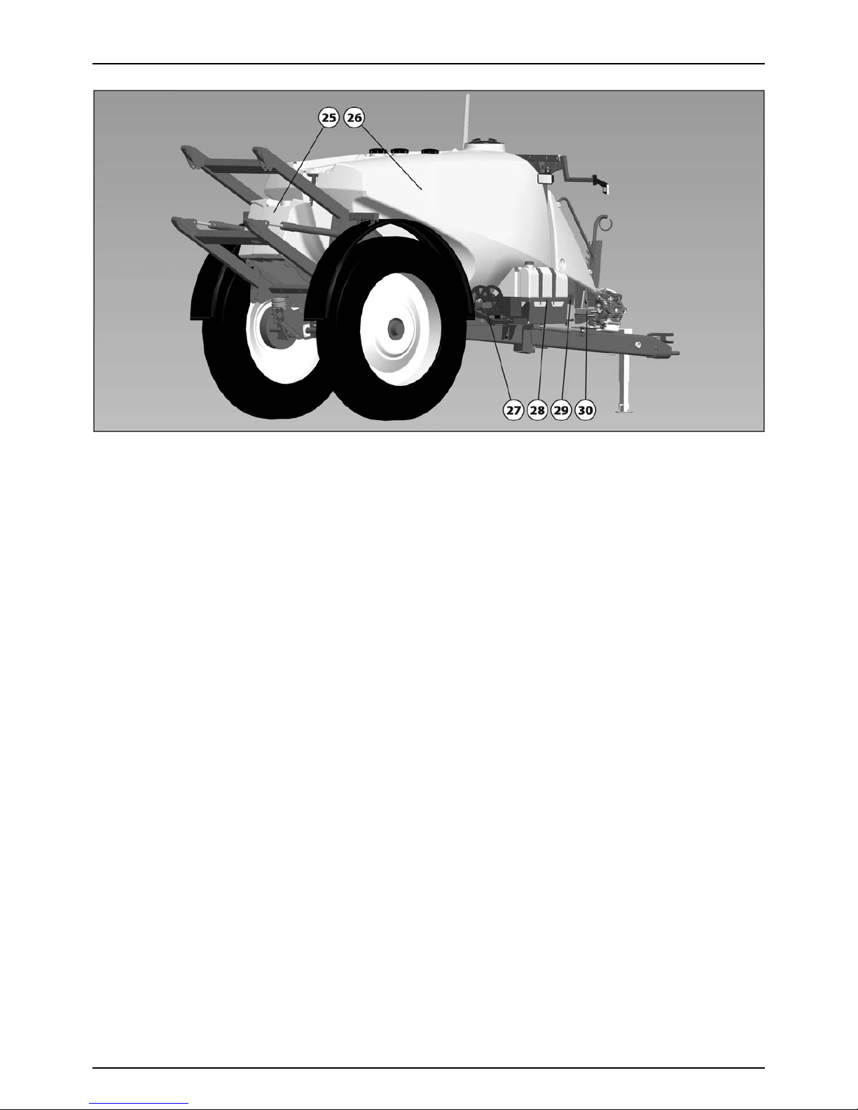
View
25. RinseTank
26. Main Tank
27. N/A
28. ChemLocker with FoamMarker Tank
29. CycloneFilter
30. Support Leg Storing Position
3 - Description
13
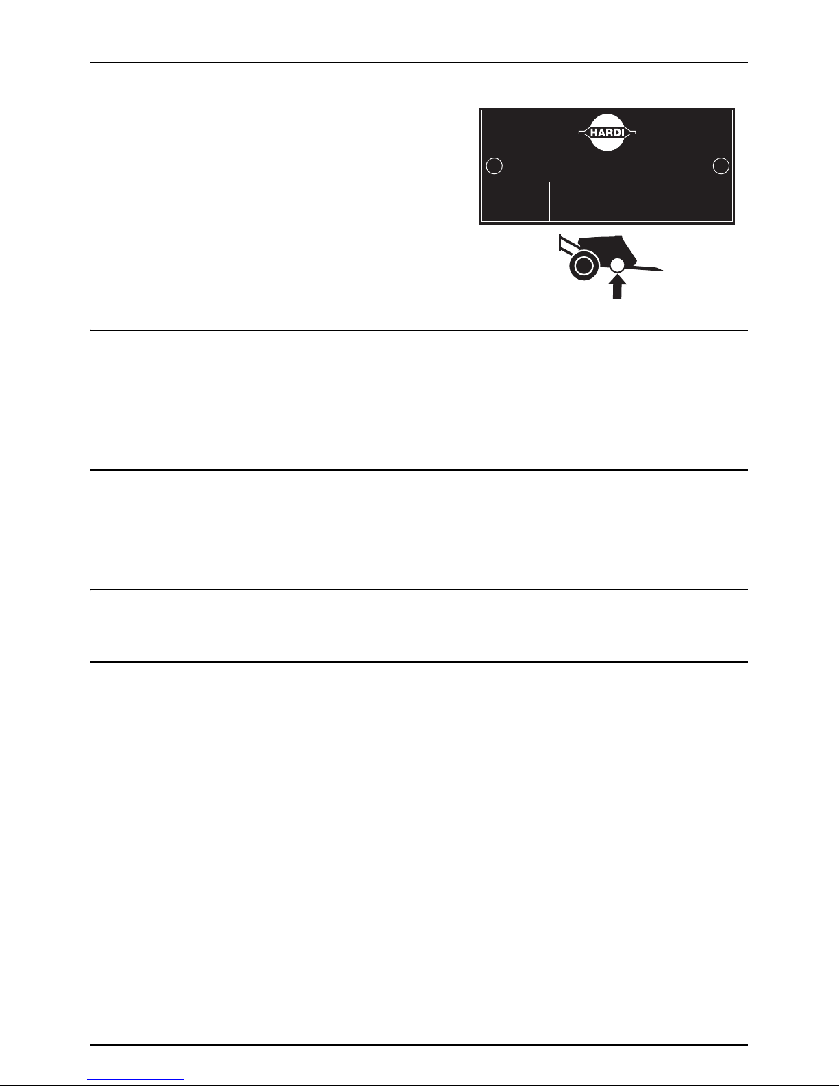
Identification plate
An identification plate is located on the chassis on the right hand side
of the sprayer. The reference number on plate will help you and your
HARDI dealer to clearly identify your machine and assist in the correct
supply of spare parts and service information.
Road worthiness
When driving on public roads and other areas where the highway code applies, or areas with special rules and regulations
for marking and lights on implements, you should observe these and equip implements accordingly.
μ
ATTENTION! Max. driving speed for models without brakes and for models equipped with brakes is different. Be aware
that these speeds may differ due to local law. Contact local authorities for information of max. driving speeds!
Sprayer Use
The HARDI sprayer is for the application of crop protection chemicals and liquid fertilisers. The equipment must only be used
for this purpose. It is not allowed to use the sprayer for any other purposes. If no local law demands that the operator must
be certified to use spray equipment, it is strongly recommended to be trained in correct plant protection and in safe
handling of plant protection chemicals to avoid unnecessary risk for persons and the environment when doing your spray
job.
Frame
Very strong and compact frame which also has a strong chemical and weather resistant electrostatic lacquer coat. Screws,
nuts, etc. have been DELTA-MAGNI treated to be resistant to corrosion.
Tank s an d Eq u i p m e nt
The main tank made of impact-proof, UV-resistant and chemical resistant polyethylene, has a purposeful design with no
sharp corners for easy cleaning. The filling hole is placed so it can be accessed from the platform. This ensures an easy access
for the filling of sprays, cleaning of the tank, etc. The sprayer is also equipped with a rinsing tank and a clean water tank. An
optional large, easy to read tank contents indicator can be placed beside the platform and is visible from the tractor cabin.
Nominal contents 3000 / 4000 / 5000 or 6000 litres.
HARDI AUSTRALIA PTY. LTD.
SERIAL NUMBER
3 - Description
14
Liquid System
Pump
Diaphragm pump with 3 diaphragms, model 1303 or diaphragm pump with 6 diaphragms, model 363 or 463.
Standard = 540 rpm (6 splines shaft). Optional = 1000 rpm (21 splines shaft). The design of the diaphragm pump is simple,
with easily accessible diaphragms and valves which ensures liquid does not contact the vital parts of the pump.
Valves and Symbols
The possible functions of valves are distinguished by coloured identification on the function labels. The modular valve
system facilitates the addition of optional extras on both pressure side and suction side. A function is activated by turning
the handle towards the desired function.
μ
ATTENTION! Only the functions used should be open - always close remaining valves.
μ
ATTENTION! If a valve is too tight to operate - or to loose (= liquid leakage) - the valve needs to be serviced. Please see
“Adjustment of 3-Way Valve” on page 88 for further information.
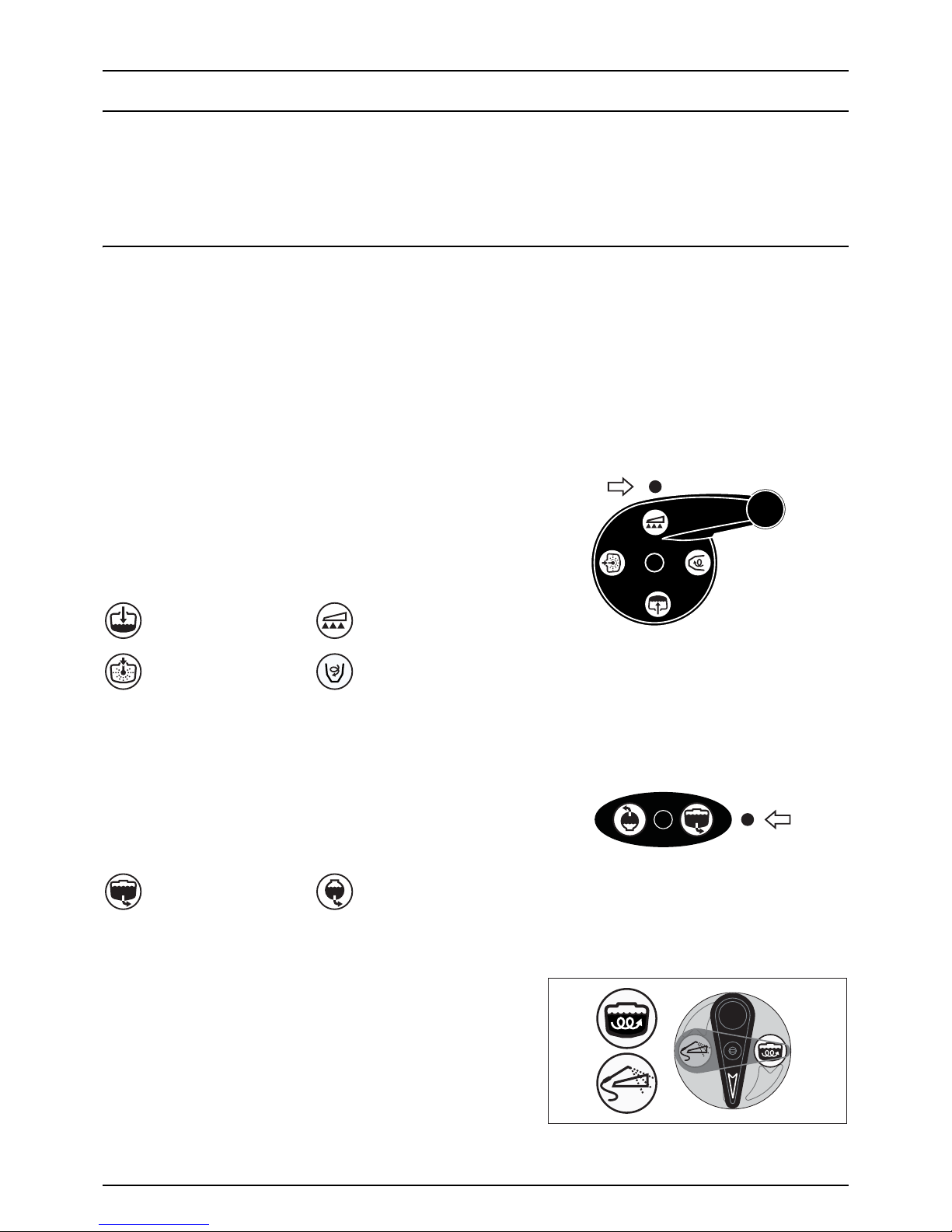
Pressure SmartValve (Green Symbols)
This valve is to select which function the pressurized liquid from the
pump will be routed to.
The active function is indicated by the indicator. The handle is turned
so the indicator points to the label for required function. If handle is
turned to a position without label (unused function) then the valve is
closed.
Suction Valve (Blue symbols)
This valve is to select suction from main tank or from the rinsing tank.
The handle is turned so the label for required function is directed to the
indicator. If handle is turned to vertical position (indicator not pointing
at a label) then the valve is closed.
Agitation Valve (Green symbols)
With the adjustable Agitation valve it is possible to combine spraying
with a high volume rate at high pressure with agitation at the same time.
This is controlled continuously by the valve: The valve is marked with an
arrow on the disc that indicates the amount of liquid that passes
through the valve.
• Handle is turned to a position near the tip of the arrow: Only a
small amount of liquid is allowed to pass the valve resulting to a
lesser extent of agitation.
Main tank Spraying
IInternal tank cleaning
(Rinsing nozzles)
(optional)
Pressure to hopper
(optional)
Main tank Rinsing tank (optional)
3 - Description
15
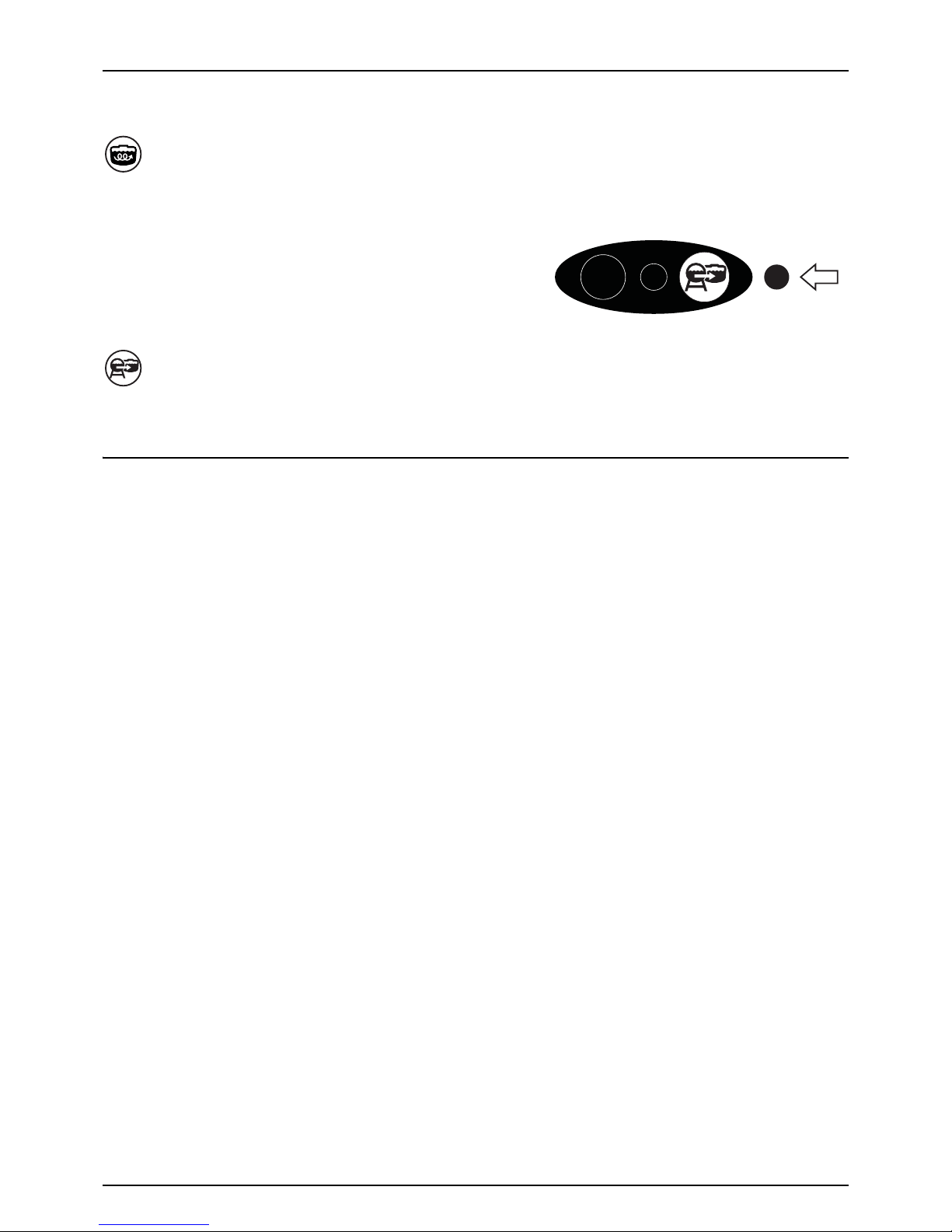
• Handle is turned to a position in the wide end of the arrow: A large amount of liquid will pass the valve resulting to a
large extent of agitation.
External Filling Device Valve (Blue symbol) (optional)
The valve is used when filling from an external tank or reservoir.
Activating valve, starts/stops the filling process.
÷
NOTE! that the suction valve must be closed for maximum filling
capacity.
RinseTank
A rinsing tank is mounted to the rear of the sprayer. The tank is made of impact-proof and chemical resistant polyethylene.
Nominal content is approximately 450 litres.
Adjustable Agitation
External filling

3 - Description
16
DynamicFluid4 Pressure Regulation
Traditional fluid regulation starts, when the nozzles are opened. With DynamicFluid4 (DF4), the regulation is a continuous
process, even if the nozzles are closed. Two ceramic discs regulate the pressure and ensure quick reaction and zero leakages.
Used parameters are sprayer speed, PTO speed and the number of activated sections. The benefit is more precise application
rates from the second the sprayer begins spraying.
The DynamicFluid4 uses feed forward technology based on 5 sensors, which feed the JobCom computer with data
necessary for optimal regulation. It auto-primes at start-up and starts to move the valve towards the final position,
immediately after the operator makes changes. For example, when section valves are opened or closed, the regulation valve
is started at the same time as the section valve motors are started. This avoids overpressure situations e.g. after running
empty and refilling of the main tank.
The 5 sensors are also back-up for each other, ensuring that the system can continue regulation - even if one or more sensor
signals fails. The applied sensors measure:
• Sprayer speed (km/h)
• Fluid flow (l/min)
• Fluid pressure (bar)
• Pump speed (rpm)
• Regulation valve opening angle (°)
Features for DF4
• Very fast and accurate regulation when all sensors are ok, setup in menus are correct, and pump, filters and valves are
in good condition.
• Quick reacting valve, when sections are turned ON/OFF, and at speed changes.
• Optimized AutoSectionControl feature that predict boom sections to open and optimized nozzle pressure.
• Optimized for different PTO systems.
• Nozzle surveillance. No setup or tuning is required for nozzle change.
• Warning in display, if failures occur on boom plumbing, such as severe clogging of line or nozzle filters or because of
large leakages on hoses and fittings.
• All functions work through with degraded performance (Limp-home modes), if:
• Failures occur in fluid system, e.g. pump defects, clogged filters or leaking valves.
• Failures occur on pressure sensor, flow sensor or pump sensor.
• There is a wrong setup of sprayer data in the menus.
• Emergency mode, if angle sensor or sprayer speed sensor fails.
Screen icons
The sprayer driver selects one of three modes: Auto, Manual or Increment Steps. The sprayer computer detects one of three
regulation modes: Drop, Question Mark or Calibration Jug. This makes 9 modes in total.
Auto Manual Increment Steps
Automatic Volume
Rate.
Manual Pressure
Control.
Volume Rate is
changed in steps as
%-up or %-down.
Press a button on the controller box to select regulation mode.
Calibration Jug
Flow to the section valves.
Nozzle size (l/min at 3 bar) has been calculated.
Drop
No flow to the section valves.
The pump is not started, or the pressure SmartValve is set to another function than
spraying.
Question Mark
Flow to the section valves, but pressure and flow has not yet been stable, therefore the
nozzle size (l/min at 3 bar) has not yet been calculated.
The system uses the last saved nozzle size.
3 - Description
17
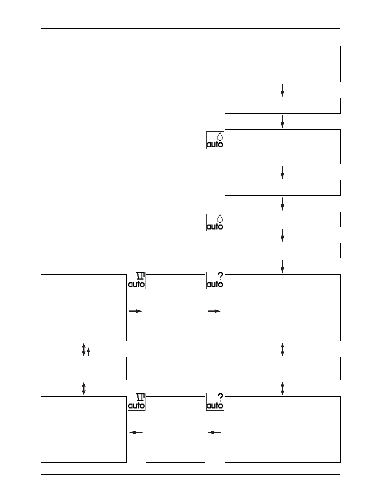
Function Diagram for Regulation Valve
μ
ATTENTION! Auto-mode icons are shown, but they could be
Manual or Increment Steps icons, depending on driver selection.
Spray job begins
Start condition:
Controller is turned OFF. Pump is turned OFF.
Pressure SmartValve to pressure draining/TurboFiller. Suction
SmartValve to main tank. Water in main tank.
Driver action
Turn the controller ON.
Controller reaction
Controller detects no pressure or flow.
Starts in auto-mode. Sets regulation valve to safe angle to
avoid overpressure at pump start, and to ensure that software
detects, that pump is started (avoiding delay).
Driver action
Turn the pump ON.
Controller action
Controller detects no pressure or flow. Stay in safe position.
Driver action
Turn Pressure SmartValve to Spraying.
Controller reaction
Headland (boom is closed)
Software uses nozzle size and feeds forward
to prepare for opening of boom.
Max. pressure limit is disabled, because last
saved nozzle size is reliable, and therefore the
software “dares” to close the regulation valve
completely.
Headland (boom is closed)
for over 5 minutes
Boom has been closed for a
longer period, so that operator
could have changed to
another nozzle size. Last saved
nozzle size becomes
unreliable.
Software enables maximum
pressure limit.
Controller reaction
Headland (boom is closed)
Controller detects pressure at armature and bypass flow back
to tank. Software uses last saved nozzle size and feeds forward
to prepare for opening of the boom.
Max. pressure limit is enabled, because last saved nozzle size
is unreliable, and therefore the software will not close the
regulation valve completely. PrimeFlow booms are primed.
Driver action
Turn Main valve OFF at headland.
Turn Main valve ON to spray.
Driver action
Turn Main valve OFF at headland.
Turn Main valve ON to spray.
Controller reaction
Spraying (boom is open)
Boom is open and sprays.
Both flow measurement and pressure
measurement are good, and the actual
nozzle size is calculated.
The actual nozzle size is used to adjust to
correct volume (liter/hectare).
Flow and pressure are
good
Both flow measurement and
pressure measurement are
good.
Software disables maximum
pressure limit.
Controller reaction
Spraying (boom is open)
Boom is open and sprays.
Software uses last saved nozzle size and pressure sensor to
adjust to correct volume (liter/hectare).
Max. pressure limit is enabled to avoid overpressure. in case
operator has changed to smaller nozzles.
3 - Description
18
Filters
A EasyClean suction filter is fitted in the working zone.
A Cyclone pressure filter is fitted to the sprayers right side just in front of the ChemLocker (optional equipment). It has a builtin self-cleaning function.
In-line pressure filters can be fitted at each boom section as an option.
Nozzle filters are fitted at each nozzle.
All filters should always be in use and their function checked regularly. Pay attention to the correct combination of filter and
mesh size (see “Spray Technique” book).
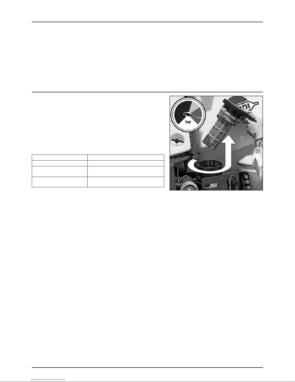
EasyClean Filter
To ensure proper function of filter and its built-in valve the filter must be
opened at least once every month. A label on the lid also designates this.
• To open filter then turn it counterclockwise and pull it up, like
shown on picture.
• Pull out the two locks (A) to remove filter element from the lid.
Besides the spray pressure gauge on the platform an EasyClean
clogging indicator is located:
Clogging indicator colour Filter status
Green indicator. No cleaning necessary.
Yellow indicator. It is possible to finish an ongoing spraying job and
then clean filter afterwards.
Red indicator. Clean the EasyClean Filter immediately, as the filter is
clogged.
3 - Description
19
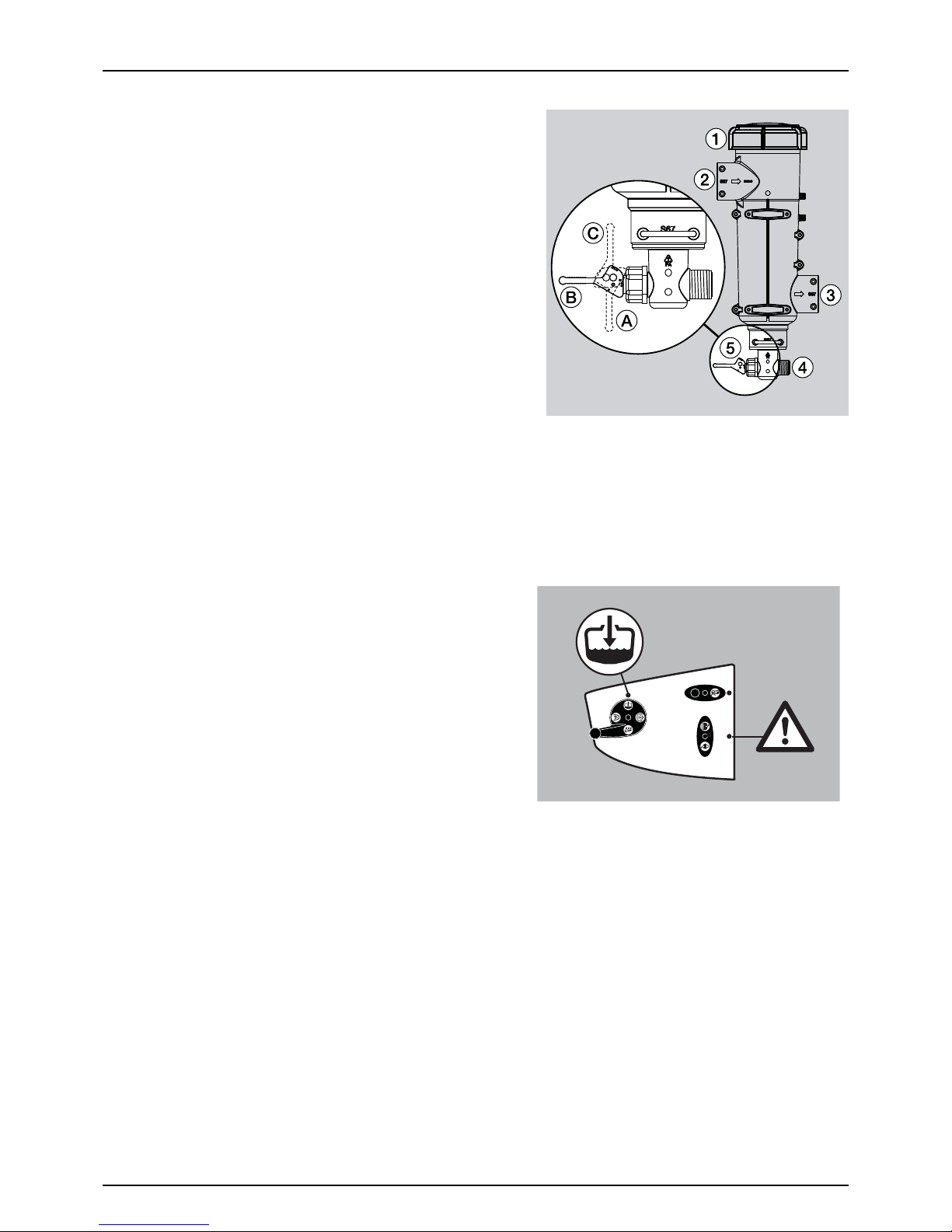
CycloneFilter
With the CycloneFilter any impurities in the spray liquid will by-pass the
filter and be re-circulated back to the tank via the return flow.
Function diagram
1. Filter lid
2. From pump
3. To boom
4. Return to tank
5. Return valve
Valve (5) has three positions marked with small dots on the lever:
A. This position marked with 1 dot: There is no return flow. Position is
used when rinsing the boom if there is spray liquid in the main
tank. Also used when high spraying volume is required.
B. This position marked with 2 dots: Normal spraying position. With
return flow to prevent filter is going to be clogged when spraying.
This position is used when rinsing the boom if the main tank is empty.
C. This position marked with 3 dots: Flushing position which is used if filter is clogged. Lift and hold the lever to use this
position which largely increases return flow and flushes the filter. The pressure SmartValve must be set to “Spraying”.
μ
ATTENTION! Use of position C is no guarantee for a clean filter. Always regularly do a visual inspection and cleaning
of the filter. If necessary see “10 Hours Service - CycloneFilter” on page 80.
€
DANGER! Never open the Cyclone filter unless the suction
valve is closed and the pressure SmartValve is turned to “Main
tank”. Otherwise, spraying liquid may hit you when opening
the filter, and drain from the main tank!
3 - Description
20
Chem Filler options
The optional HARDI® VACnMIX or HARDI® TURBO FILLER are located on the sprayer’s left side, just behind the MANIFOLD
valves.
HARDI®VACnMIX (optional equipment)
The HARDI VACnMIX™ is used for the mixing of plant protection or
liquid fertiliser chemicals into a solution, and transferring the solution
to Main Tank.
Your Vacuum VACnMIX™ uses the latest design and technology to
provide fast, safe and accurate transfer of liquids, powder or granules.
The Vacuum VACnMIX is a multi-purpose hopper. It is designed for
use in closed system transfer and utilises the tough and reliable Hardi
pump on your sprayer. The rate of transfer is controlled by the
operator.
The VACnMIX is supported on a sturdy lift frame and is equipped with
two vortex mixing jets, a control manifold and a rotating chemical
drum rinse nozzle. The hopper flushing ring is connected to the sight
tube to enable decontamination of both together. The unit has a
water supply inlet port, and a vacuum suction outlet port — for
transfer of either dilute or concentrated liquid chemicals to the spray
tank.
The vortex jets provide vigorous operator-controlled agitation which
mixes granules into solution, or allows liquid chemical concentrate to be pre-mixed. Any granules that do not dissolve are
kept in suspension in the vortex until they disperse.
Featuring a Vacuum and Transfer Valve and an in-line venturi with interchangeable restrictors (based on pump capacity), the
unit can transfer liquid from a clean water source or Envirodrum into the hopper, and from the hopper to the main sprayer
tank.
Vacuum / Transfer Valve (only if equipped with VACnMIX)
This valve is located behind the Chemical Induction Hopper and is used
to control the filling / emptying of the VACnMIX hopper.
FILL
EMPTY
3 - Description
21
Control Manifold VACnMIX
Fast Fill valve/Vortex Control valve
ATTENTION! The Vacuum/Transfer valve must be set to either Fill or
Empty to activate the Fast Fill valve.
The Fast Fill valve (A) is used to fill the VACnMIX. Turn the valve to on
to fill the hopper with water. Watch the level of water. Fill to the 25
Litre level, which will be just above the upper jet. When sufficient
water is in the hopper turn Fast Fill handle off.
÷
NOTE: Sight gauge is a guide only to fluid volume in hopper).
Vortex G eneration
The Fast Fill/Vortex Control valve can also be used to activate a vortex flushing of the VACnMIX. To start a vortex in the hopper
turn the Upper & Lower Jet valves (C) (D) to ON and turn the Fast Fill valve (A) to OFF.
Vortex force can be controlled by positioning the Fast Fill valve (A) between on/off to achieve desired rate of swirl action.
Further control of the vortex action can be achieved by partially or fully closing one of the jets.
Hopper Rinsing Ring valve
The VACnMIX has a rinsing ring located under the upper lip of the hopper
that uses spray liquid to flush the walls of the hopper.
The Flushing ring valve (B) is used to rinse the hopper after use. With the lid
closed, flush the hopper using the rinse ring. Control the rinse by turning
flush ring handle on VACnMIX control manifold to the ON / OFF position.
€
DANGER! Do not activate the rinse ring unless the hopper lid is closed
to avoid spray liquid hitting the operator.
μ
ATTENTION! Rinsing device uses spray liquid to rinse hopper. Always
avoid contact with chemical solution.
μ
ATTENTION! The hopper rinsing devices use spray liquid for rinsing
the hopper. The VACnMIX must always be cleaned/decontaminated
together with the rest of the sprayer with fresh water when the spray job is complete.
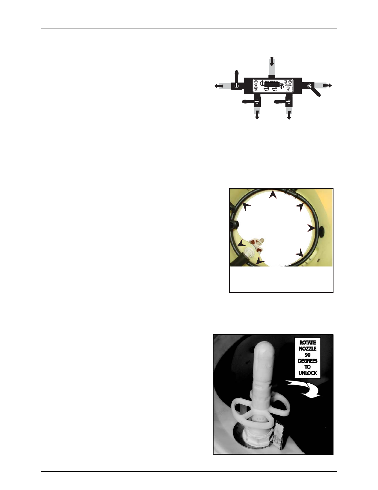
Chemical Container Rinsing Device
The VACnMIX comes equipped with a container rinsing nozzle which
uses spray liquid from the main tank to rinse chemical containers.
€
DANGER! Do not press the nozzle unless it is covered by a
container to avoid spray liquid hitting the operator.
μ
ATTENTION! Rinsing device uses spray liquid to rinse
containers. Always rinse the chemical containers with clean
water several times before The rinse nozzle lock is released by
turning the upper section 90 degrees
÷
Note: This lock acts as a safety measure to prevent injury to
operator. Ensure lock is repositioned correctly after use.
A
B
C
D
SLOW
ON
OFF
HOPPER RINSE RING
(viewed from inside hopper)
3 - Description
22
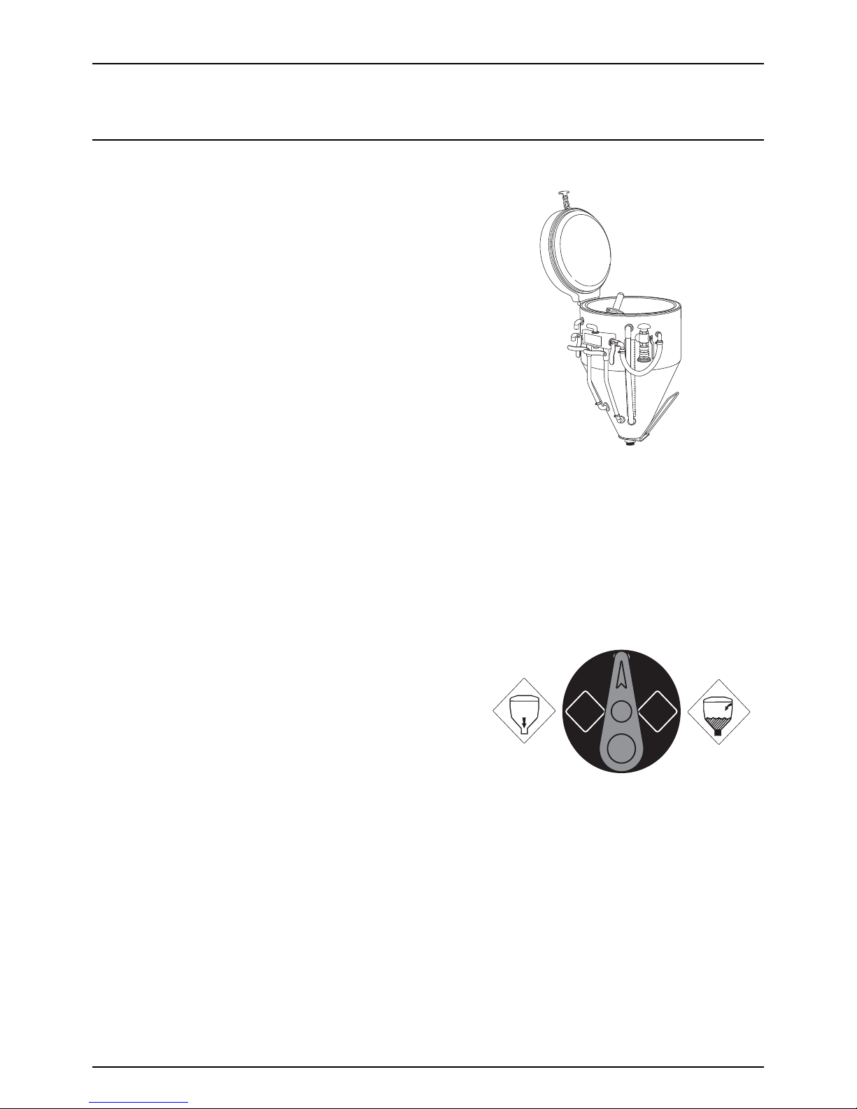
HARDI®TURBO FILLER (optional equipment)
The TurboFiller is situated in the working zone on the sprayers left side.
When being used it should be unlocked by pulling the handle (A)
situated to the right of the TurboFiller and pushed down (B) by grabbing
the handle on the TurboFiller until it clicks into locked down-position.
When retracting the TurboFiller after use, then unlock it by pulling the
handle (A) situated to the right of the TurboFiller and pull it back in
storing position until it clicks into the lock.
±
WARNING! Before releasing the lock (A) always keep a hand on
the grip to avoid abrupt movement of the TurboFiller!
Before use
• Pull the handle (A) to unlock.
• Grab the handle to push TurboFiller down (B) until it clicks into
locked down-position.
After use
Pull the handle (A) to unlock.
• Grab the handle to pull TurboFiller back in storing position until it locks.
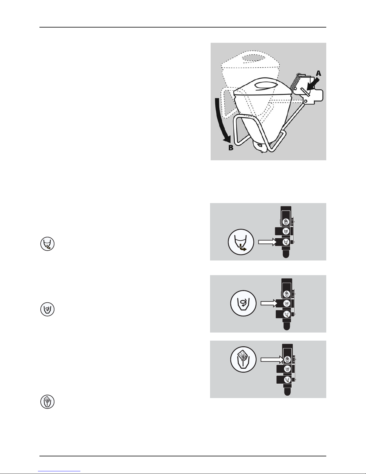
TurboFiller Suction Valve
The valve is used simultaneously with the TurboFiller. The valve has 2
settings: Continuously open or spring loaded normally closed. Open the
valve when chemicals are to be filled into the TurboFiller and transferred
to main tank.
TurboDeflector Valve
This TurboDeflector valve activates the Vortex flushing of the TurboFiller.
Lift the lever to lock it in open position for continuous liquid rotation in
the hopper.
Chemical Container Rinsing Lever
The upper lever is used for two purposes:
When the TurboFiller lid is open: For rinsing empty containers. Place the
container over the rotating flushing nozzle in the middle of the
TurboFiller to rinse the inside of the container.
When the TurboFiller lid is closed: Use the Chemical Container Rinsing
lever to rinse the hopper when the filling of chemicals is completed.
€
DANGER! Do not press the lever unless the multi-hole nozzle is covered by a container as spray liquid may other wise
hit the operator.
Suction from TurboFiller
Start TurboDeflector
Chemical Container Rinsing

3 - Description
23
Clean Water Tank
A clean water tank is integrated into the right side cover. It is accessed
for filling at the sprayers right side when entering the platform. The ball
valve is located on the valve cover below the EasyClean filter on sprayers
left side. The water in this tank is for hand washing, cleaning of clogged
nozzles etc. Only fill this tank with clean water from the well.
Capacity: approximately 20 litres.
±
WARNING! Although the clean water tank is only filled with clean
water, this water must NOT be used for drinking.
DilutionKit (optional)
The dilution kit consist of four valves added to the liquid system, enabling the rinse water to be directed from the rinse tank
into the main tank and piping to dilute spray liquid residues.
The dilution kit will ease diluting of chemicals in main tank or boom piping done from the drivers seat while driving in the
field. This can be useful when interrupting a spray job, e.g. because of rain or before the tank has to be re-filled at the farm.
The dilution kit has two functions that is selected with the optional function switch on the spray controller.
• Tank dilution: Dilute boom piping and the main tank at the same time.
• Boom dilution: Dilute the boom piping only.
÷
NO TE! Dilu tion of che mical res idues may b e req uire d by l aw in cer tai n sit uatio ns be for e re turni ng to the fa rm fo r fill ing
or cleaning. Please familiarize with current rules and follow them.
3 - Description
24
BoomPrime (optional)
BoomPrime is a low pressure circulation system, which primes the spray boom tubes prior to spraying, ensuring a
homogenous fluid in the boom tubes and in the main tank. Below the illustration shows the BoomPrime system for the
boom. Components are explained in the diagrams for the liquid systems.
•
The BoomPrime system is attached to each end of a boom section (A).
• The boom spray sections are fed into the middle of each section (B).
Liquid for BoomPrime is taken from a bypass valve (D) just before the flowmeter. This valve operates in opposite phase:
When priming, the direction of liquid flow will be reversed. The liquid will be fed into the nozzle tubes from each end, and
they will then return any water back to the main tank through the EFC section valves dump line (C).
The BoomPrime pressure is adjusted by the handle on the valve (D), which comprises a pressure gauge.
See “BoomPrime Adjustment (optional)” on page 44 for adjustment.
Operating state Section valves Bypass valve
Spraying Open Closed
Not spraying Closed Open
B
C
D
A A A A A A A ABBB
3 - Description
25
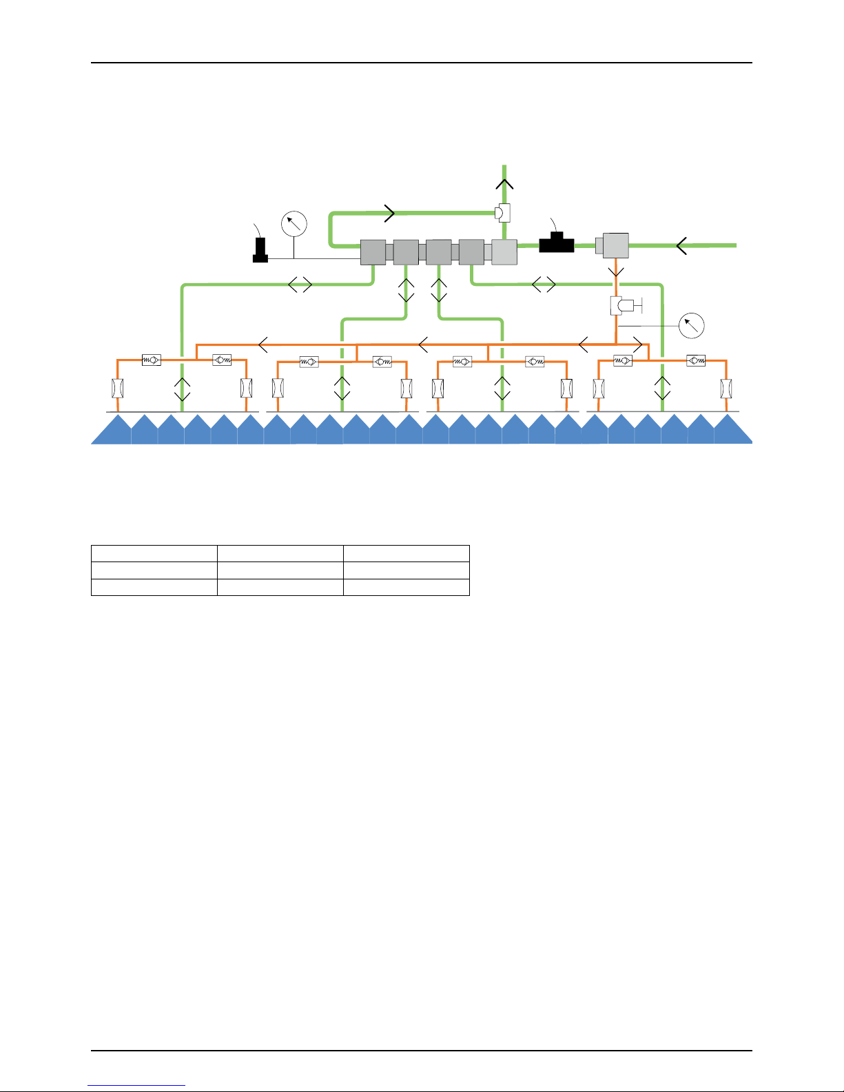
Diagram - Basic Liquid System
1. Pump
2. EasyClean filter
3. Suction Valve for Main tank/RinseTank
4. Pressure Control Valve
5. Pressure SmartValve
6. CycloneFilter
7. Return Line for Boost Function
8. Bypass Valve for Boom
9. Distribution Valves
10. Flow meter
11. Spray Boom
12. Agitation Valve
13. Agitation Tube
14. Tan k Hose for Ret u r n Lines (Riser Pi pe)
15. Safety Valve
16. One-Way Valve
17. Tan k Hose (Riser Pipe)
18. Tank Rinsing Nozzles
19. Rinse Tank Coupler
20. Rinse Tank
21. Valve Block TurboFiller
22. Ejector TurboFiller
23. TurboFiller
17
14
3
1
2
6
16
16
16
19
16
4
5
7
8
10
9
20
18
13
16
22
23
21
11
12
15
3 - Description
26
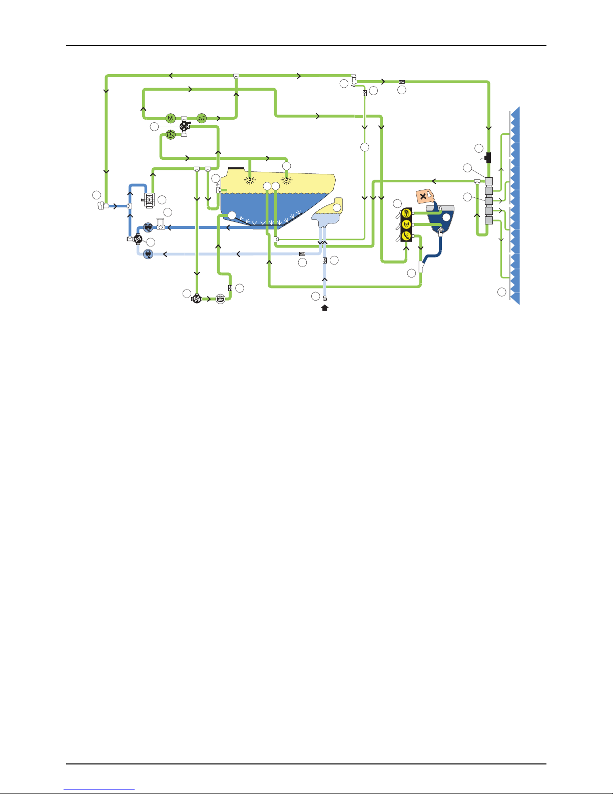
Diagram - Liquid System with Options and TurboFiller)
1. Pump
2. EasyClean filter
3. Suction Valve for Main Tank / RinseTank
4. Pressure Control Valve
5. Pressure SmartValve
6. CycloneFilter
7. Return Line for Boost Function
8. Bypass Valve for Boom
9. Distribution Valves
10. Flow meter
11. Spray Boom
12. Agitation Valve
13. Agitation Tube
14. Tank Hose for Return Lines
15. Safety Valve
16. One-Way Valve
17. Tank Hose ( R iser Pi pe)
18. Tank Rinsing Nozzles
19. Filtered Fast Fill (optional)
20. Rinse Tank
21. Valve Block TurboFiller
22. Ejector TurboFiller
23. TurboFiller
24. Tank Hose for Turbofiller
25. FastFiller Ejector
26. Filling Valve
27. Pressure Gauge for Boom
28. Pressure Sensor
29. Filling Coupler
30. FastFiller Hose to Tank Inlet
31. Restrictor for BoomPrime
32. One-Way Valve for BoomPrime
33. Bypass Valve for BoomPrime
34. Pressure Control Valve for BoomPrime
35. Pressure Gauge BoomPrime
BoomPrime
26 3
1
2
12
11
27
6
16
16
16
16
4
5
7
8
10
9
25
30
20
28
18
13
16
8x
8x
32
31
34
33
35
Clean Water
Fill ONLY
1424
15
19
23
22
21
17
29
36
3 - Description
27
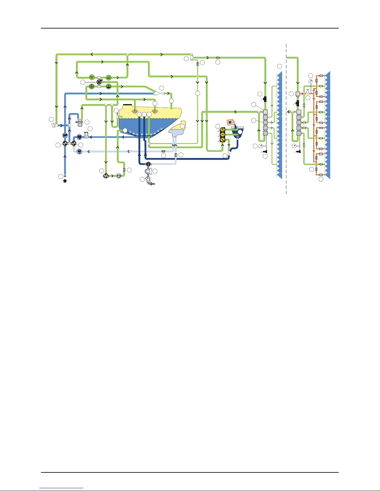
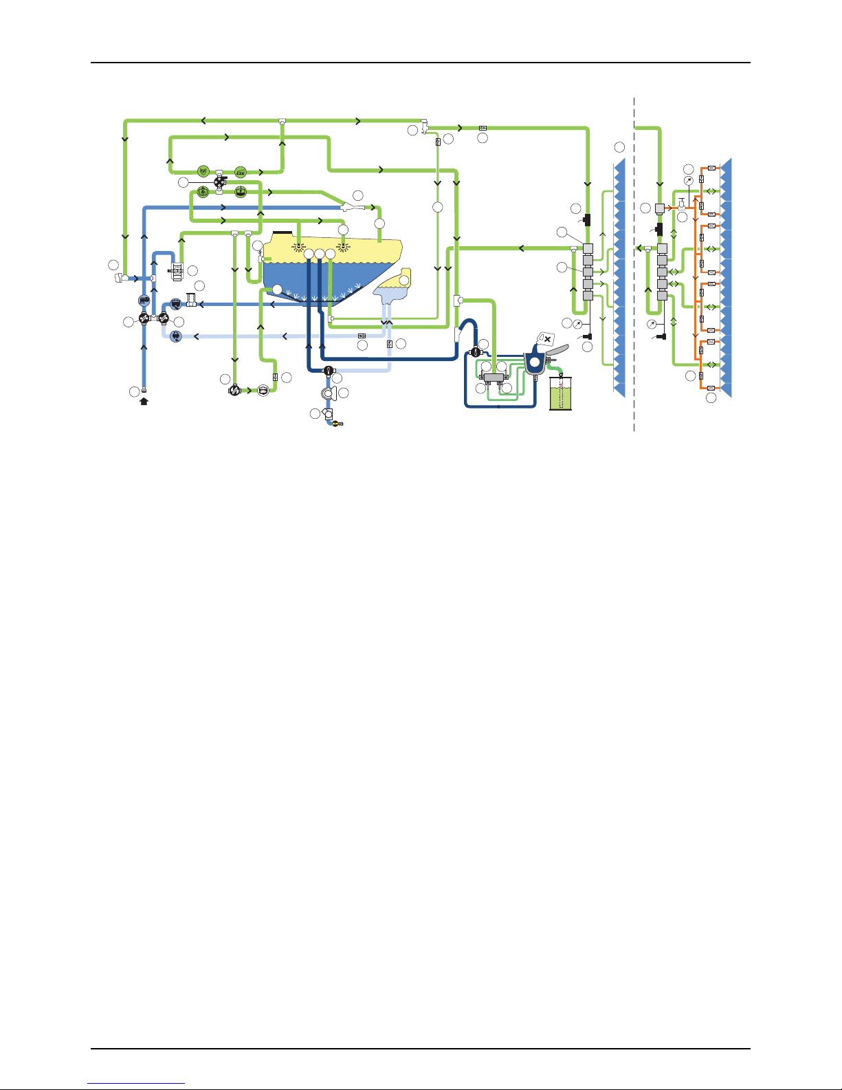
Diagram - Liquid System with Options and VACnMIX
1. Pump
2. EasyClean filter
3. Suction Valve for Main Tank / RinseTank
4. Pressure Control Valve
5. Pressure SmartValve
6. CycloneFilter
7. Return Line for Boost Function
8. Bypass Valve for Boom
9. Distribution Valves
10. Flow meter
11. Spray Boom
12. Agitation Valve
13. Agitation Tube
14. Tank Hose for Return Lines
15. Safety Valve
16. One-Way Valve
17. Tank Hose ( R iser Pi pe)
18. Tank Rinsing Nozzles
19. Filtered Fast Fill
20. Directional Fill Valve
21. Rinse tank
22. Filling Coupler
23. Vacuum Transfer Valve
24. VAC nMIX
25. Chemical container flush valve
26. Upper Vortex Jet valve
27. Fill / Vortex control valve
28. Lower Vortex valve
29. Tan k Hose VACnMIX
30. Fast Fill Ejector
31. Filling Valve
32. Pressure Gauge Boom
33. Pressure Sensor
34. Restrictor for BoomPrime
35. One-Way Valve for BoomPrime
36. Bypass Valve for BoomPrime
37. Pressure Control Valve for BoomPrime
38. Pressure Gauge BoomPrime
BoomPrime
31 3
1
2
12
11
6
16
16
16
16
4
5
7
8
10
9
30
34
21
33
18
13
16
8x
8x
35
34
37
36
Clean Water
Fill ONLY
1429
15
19
17
22
5
4
24
25
26
28
27
23
32
20
38
36
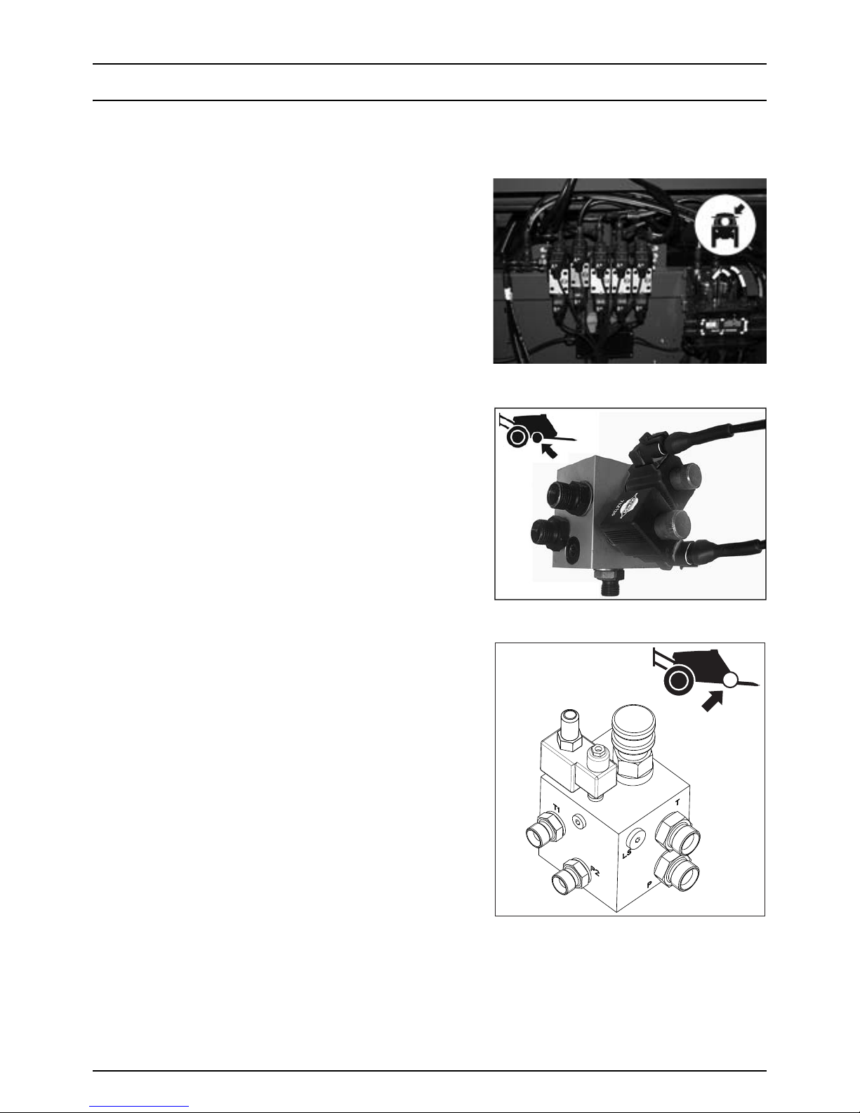
3 - Description
28
Hydraulic Systems
Hydraulic Blocks
Hydraulic blocks fitted to the sprayer are:
Boom
The main boom hydraulic block that manages hydraulic pressure for the
boom controls.
ParaLift
This hydraulic block manages hydraulic pressure for the ParaLift.
Open Centre Hydraulics
The open centre hydraulic block is necessary if the tractor uses open
centre hydraulics and/or load sensing. For adjustment, see “Open Centre
Hydraulics (optional)” on page 39.

3 - Description
29
AutoHeight UC5
On sprayers with AutoHeight, this hydraulic block manages hydraulic
pressure for the automatic boom height control functions.

3 - Description
30
Boom
Boom configuration, terminology and Operators Manual
The Navigator range is available with a choice of optional boom configurations and widths. For this reason a separate “Boom
Operators and Maintenance Manual” is supplied with your sprayer and contains detailed information on boom safety, setup, operation, maintenance and spare parts.
€
DANGER! Important information on Safety, Operation and Maintance specific to your boom configuration is detailed
in the “Boom Operators Manual” supplied with your sprayer’s documentation. It must be read and fully understood
by anyone intending to operate this equipment. Failure to do so could result in serious personal injury or death.
Booms are available in 18 to 36.5 meters depending on boom configuration.
For 2-folded the terminology is as follows:
A. Breakaway section
C. 1st outer wing
E. Inner section
F. Centre section
For 3-folded booms the terminology is as follows:
A. Breakaway section
B. 2nd outer wing
C. 1st outer wing
E. Inner wing
F. Centre section
÷
NOTE! When controlling the boom at the SetBox, the folding
sections are:
X. 2nd outer wing
Y. 1st outer wing
Z. Inner wing
Boom Hydraulic system
There are two different versions of hydraulic system
Y-version (only available on Eagle booms)
• Operated via the tractors hydraulics.
• Hydraulic lift cylinder for boom height adjustment.
• Two cylinders for simultaneously boom wing fold and unfold.
• Slant is optional equipment, which is operated directly by the tractor hydraulics.
Z-version
• Same features as the above mentioned Y-models, however provided with more advanced hydraulics controlled from
a hydraulic control box.
• Two boom wing tilt cylinders that give the ability to obtain individual boom wing tilt.
• Individual boom wing fold.
• Slant is optional equipment, which is operated directly from the hydraulic control box.

3 - Description
31
Safety info
The boom must not be folded/unfolded while driving! Never use the folding/unfolding functions before the sprayer has
been stopped! Failure to do so will damage the boom.
€
DANGER! Before unfolding the boom it is important to connect the sprayer to the tractor to prevent overbalancing
of the sprayer.
€
DANGER! When folding or unfolding the boom, make sure that no persons or objects are within the operating area
of the boom.
€
DANGER! Always follow the guidelines listed below when driving in areas with overhead power lines:
Never use the folding/unfolding functions in areas with overhead power lines.
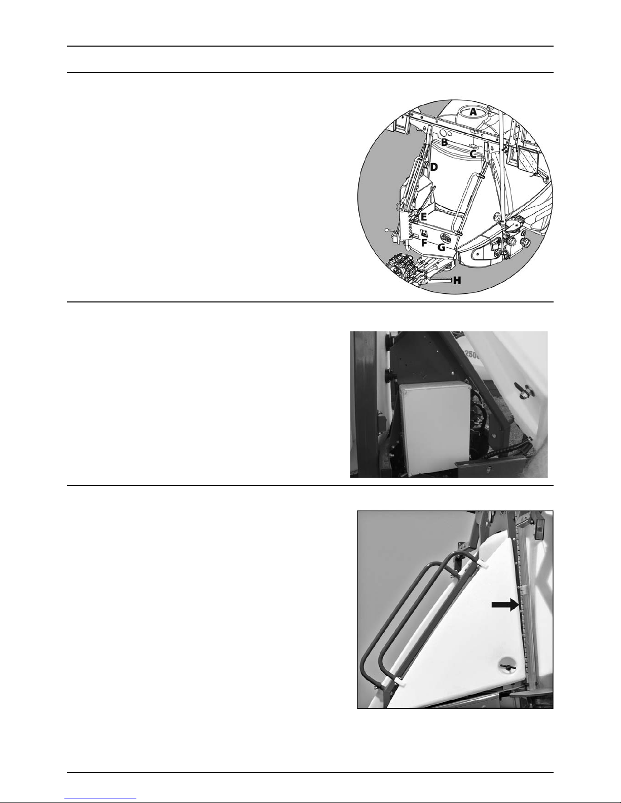
3 - Description
32
Equipment
Platform
To get access to the platform:
• Pull the step(s) up and swing the step(s) (H) out until it clicking into
locked out-position. Retract by pulling up and swing step(s) back
to locked in-position.
Components
A. Main tank lid.
B. Pressure gauge and EasyClean clogging indicator.
C. Main tank drain valve, moved to right side of main tank.
D. Clean water tank lid.
F. Pressure regulation valve.
G. Agitation valve.
H. Step(s).
Right Side Cover
The right side cover is opened by turning the handle in the lower rear
corner of the cover and lifting the cover up.
Main components:
A. JobCom box.
B. Clean water tank.
The clean water tank is integrated in the side cover. It is filled
from the platform, when the side cover is closed.
μ
ATTENTION! Only open the right side cover, when the clean
water tank (optional) is empty!
Tank Level Indicator
The actual tank level in the main tank can be observed on the tank level
indicator. The scale is displayed in litres.
μ
ATTENTION! The level indicator is only a guidance for the tank
level.
The total deviation of accuracy for the level is 7.5% for a 20% filled
tank and below. For above 20% filled tank, the total deviation of
accuracy is 5%.
Just behind the main tank scale, a level for the rinsing tank is fitted to the
frame. This is a guidance to see if the rinsing tank is full or empty. If the
guidance ball is at the top, the rinsing tank is full.
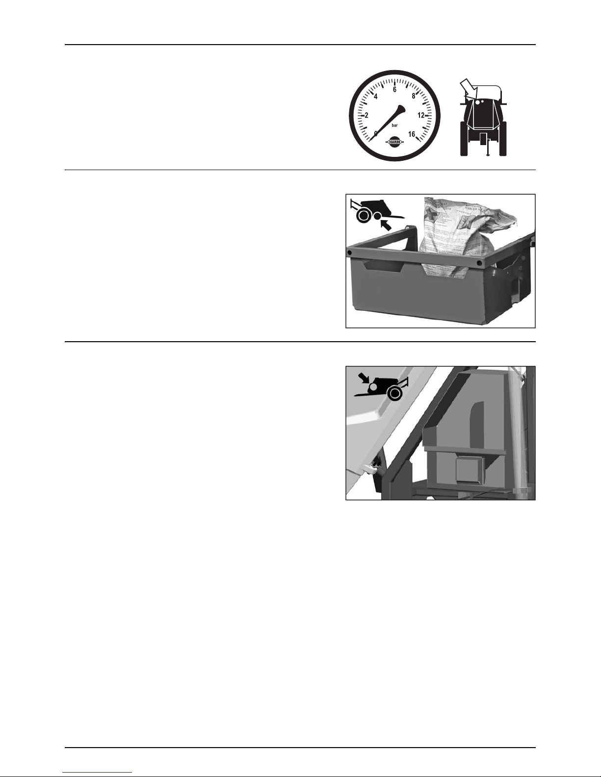
3 - Description
33
Nozzle Pressure Gauge
The remote pressure gauge is integrated at the top of the platform. This
gauge measures the working pressure in the boom tubes as close to the
nozzles as possible.
The outputs stated in the nozzle charts are always based on the pressure
measured at the nozzle. Both when calibrating and spraying, the
pressure must be adjusted according to the readings of this pressure
gauge.
ChemLocker (optional)
A ChemLocker for storage of chemical containers etc. is mounted on the
sprayers right side.
If the optional FoamMarker is selected, the FoamMarker tank is then
placed inside the ChemLocker.
μ
ATTENTION! Maximum load is 100 kg or 100 litres.
SafetyLocker
The locker is integrated in the front left side, just above the SmartValves.
It is for the purpose of storing non-contaminated protective gear, soap
for hand washing etc.
The locker is split in two compartments for the separation of clean
clothes from gloves with risk of contamination.
±
WARNING! Although this locker is meant for storing nontoxic
items, it must never be used for storing food, beverage or other
things meant for consumption.

3 - Description
34
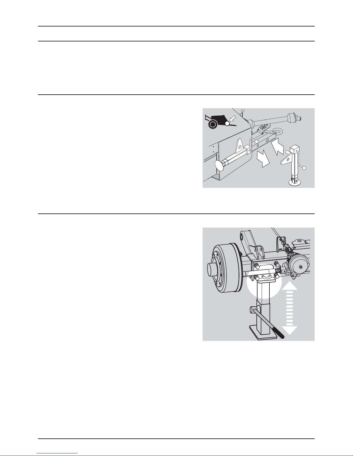
35
4 - Sprayer setup
General info
Before Putting the Sprayer into Operation
Although the sprayer has been supplied with a strong and protective surface treatment on steel parts, bolts etc. in the
factory, it is recommended to apply a film of anticorrosion oil (e.g. CASTROL RUSTILO or SHELL ENSIS FLUID) on all metal parts
in order to avoid chemicals and fertilizers discolouring the enamel.
If this is done before the sprayer is put into operation for the first time, it will always be easy to clean the sprayer and keep
the enamel clean for many years. This treatment should be carried out every time the protection film is washed off.
Support Leg
The support leg is stored in the bracket on the sprayer’s right side when
the sprayer is attached to the tractor.
To use the support leg
1. Lift the leg off the storage bracket.
2. The support leg can then be mounted to the drawbar extension
on both sides as preferred (high hitch left side only).
3. Secure with the linchpin.
To remove the support leg
1. Lift the leg.
2. Remove the linchpin and pull out the support leg.
3. Secure the leg at the storage bracket with the linchpin.
Jack Up the Sprayer
When the sprayer needs wheel mounting, wheel changing, brake or
wheel bearing changing etc. then jack up the sprayer under the axle as
shown.
€
DANGER! Be sure to place sprayer at level and firm ground to
avoid sprayer falling down from the jack.
μ
ATTENTION! It is good practice to use stop wedges at the
opposite wheel!
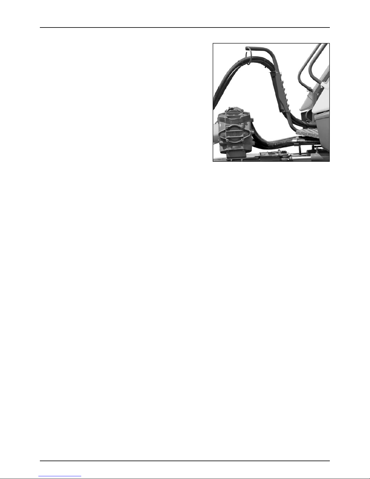
4 - Sprayer setup
36
Hose Package Support
To prevent hoses and wiring from being damaged by the tractor wheels
or the PTO shaft, all hoses, cables and wires are held by the hose package
support fitted to the sprayer platform.
μ
ATTENTION! A sprayer with IntelliTrack requires more slack in the
cables. Make sure that the hoses and cables are long enough in
tight turns, when fully steered.

4 - Sprayer setup
37
Transmission Shaft
Operator Safety
1. Always STOP THE ENGINE before attaching the transmission shaft to the tractor power take-off (PTO) - most tractor PTO
shafts can be rotated by hand to facilitate spline alignment, when the engine is stopped.
2. When attaching the shaft, make sure that the snap lock is FULLY ENGAGED - push and pull the shaft until it locks.
3. Always keep protection guards and chains intact and make sure that it covers all rotating parts, including CV-joints at
each end of the shaft. Do not use without protection guard.
4. Do not touch or stand on the transmis sion s haft, when it is rota ting - keep your safe ty distance at 1.5 me ter. A lso NE VER
cross over a rotating PTO shaft to reach the other side of the sprayer.
5. Prevent protection guards from rotating by attaching the chains allowing sufficient slack for turns.
6. Make sure that protection guards around the tractor PTO and the implement shaft are intact.
7. Always STOP THE ENGINE and remove the ignition key, before carrying out maintenance or repairs to the transmission
shaft or implement.
€
DANGER! A ROTATING TRANSMISSION SHAFT WITHOUT PROTECTION GUARDS IS FATAL!
PTO Installation
€
DANGER! As PTO shafts are dangerous in operation, always read
the manufacturer’s instruction book before applying any
changes to the transmission shaft!
First installation of the transmission shaft is done in the following way:
1. Attach the sprayer to the tractor and set the sprayer height in the
position with the shortest distance between the tractor and the
sprayer pump PTO shafts.
2. Stop the engine and remove the ignition key.
3. If the transmission shaft needs to be shortened, pull the shaft
apart. Fit the two shaft parts to the tractor and the sprayer pump
and measure how much the shaft needs to be shortened. Also
mark the protection guards with the same length to be shortened.
±
WARNING! Only shorten the shaft if it is absolutely necessary!
±
WARNING! The shaft must always have minimum overlap of half a shaft length!
The recommended overlap (A) of the two shaft parts is 2/3 of the length.
The shaft must always have minimum overlap (A) of 1/2 of the length.

4 - Sprayer setup
38
Hydraulic Systems
General Info
Ensure that the snap couplers are clean before connection!
After having operated the boom and the system has been filled with oil, check the tractor’s hydraulic oil level and top up, if
necessary.
€
DANGER! Test of the hydraulic system should be done very cautiously. There may be air trapped in the system which
can cause violent movements of the boom.
€
DANGER! Hydraulic leaks: Never use your fingers to locate a leakage in any part of the hydraulic system. Due to high
pressure, hydraulic oil may penetrate the skin.
Connecting the hydraulics
Make sure the hydraulic quick couplings are clean and dry taking care to connect the correct hoses to “Pressure” and “Tank”
(the hoses are clearly marked for positive identification). The size and number of hydraulic hoses to connect depends on the
optional equipment fitted to the sprayer. To assist in
identifying the right hoses they have been tagged with colour coded “Zip-
ties.
Requirements for tractor
Y-model requirements (Only on EAGLE Boom)
• One single acting outlet for the lift function of the spray boom.
• One double acting outlet for the folding function.
Z-model requirements
• One double acting outlet for the electro hydraulic operation of the boom functions.
Optional hydraulic system requirements:
• One double-acting outlet for the operation of the FlexCapacity pump (optional).
• One double-acting outlet for the Banjo filling pump
μ
ATTENTION! The hydraulic hoses are marked with arrows to indicate the direction of oil flow.
• The system has a built-in flow regulator that maintains constant speed on hydraulic movements.
• Oil flow between 10 and 90 l/min and a min. pressure of 190 bar.
• Maximum permissible oil pressure is 210 bar.
• Return flow restriction of the connected tractor must be maximum 15 bar.
μ
For Load Sensing systems an oil flow of approximately 3 l/min at 25 bar supplied by the sprayer hydraulics.
Function Activation Operation
Hose
size
Tag
colour
Hook up
Boom Hydraulics AB
SPC Direct Hydraulics Tractor Remote Control Lift/Lower 3/8” Green Lift /Lower Lift /Lower
SPC Direct Hydraulics Tractor Remote Control Fold 1/4” Yellow Fold-Unfold Fold-Unfold
SPC Electric over Hydraulics Switch Box Control All 3/4” Green Pressure Tank (Return)
FTZ Switch Box Control All 3/4” Green Pressure Tank (Return)
TR4 Switch Box Control All 3/4” Green Pressure Tank (Return)
B3 Switch Box Control All 3/4” Green Pressure Tank (Return)
Options
463/464 Pump Hydraulic Drive Tractor Remote Control Pump drive 1/2” Red Pressure Tank (Return)
Banjo Filling Pump Tractor Remote Control Pump drive 1/2” White Pressure Tank (Return)

4 - Sprayer setup
39
Open Centre Hydraulics (optional)
The open centre hydraulics block is necessary, if the tractor uses open
centre hydraulics and/or load sensing.
The valves (1) and (2) is factory set for open centre hydraulics, but if
closed centre hydraulics is used (also in combination with load sensing),
screw in the valve (clockwise).
Certain tractor models are able to use Load Sensing without connecting
an external sensing line. But if optimal sensing control pressure cannot
be obtained, an external sensing line needs to be connected (3). Please
consult your tractor dealer for correct setup and correct connection.
±
WARNING! Before operating the hydraulics, the valve should be
set according to the specific tractor model. If you are unsure of
the type of hydraulic system in your tractor, please contact your
tractor dealer.
Combinations of settings for flow element and circuit value:
*if the tractor requires pressure relief, contact your tractor dealer for further advice.
±
WARNING! Always be sure to fully open or close the open/closed centre selection valves. Failure to do so may cause
damage to vital pump parts.
±
WARNING! It is essential that connectors on sensing line are kept totally clean. Failure to do so can result in impurities
entering the pump and causing damage to vital pump parts.
Valve no. 123 (LS port)
Open centre Out Out Not connected
Closed centre In In Not connected
Load sensing (LS) In Out* Connected

4 - Sprayer setup
40
Electrical Connections
Power Supply
Power requirement is 12V DC. Always note polarity! For proper function
of the electric equipment, the wires must have the following
recommended cross sectional areas and correct fuses to ensure a
sufficient power supply. The delivered power connectors follows the
standard of most newer tractors. If you have a tractor with another
power connector, it is necessary to disassemble the connector and fit it
to the actual tractor connector.
The number and the type of connectors may vary on the specific
sprayer, depending on its equipment.
Cigar connector
Spray control unit requires:
Wire 2.5 mm
2
, Fuse 10 Amp
Hydraulic control unit requires:
Wire 4.0 mm
2
, Fuse 16 Amp
7-Pole traffic light connector
JobCom connector
The unit requires:
Wire 6.0 mm
2
, Fuse 25 Amp
Working light connector
The unit requires:
Wire 10.0 mm
2
, Fuse 30 Amp

4 - Sprayer setup
41
Installation of Control Unit Brackets
Find a suitable place in the tractor cabin to mount the control units. Best
recommended position is to the right of the driver seat.
The supplied tractor pillar bracket (A) has a hole spacing of 100 and 120
mm that fits most tractors. Threaded mounting holes may be hidden
behind front corner cover. Check tractor instructions manual for
information regarding attachment points.
Three mounting tubes (B) are supplied. One, two or all three may be
used. They can be bent and shortened. A spacer (C) is also supplied to
allow further attachment possibilities. Find the best solution for your
tractor or vehicle.
Tube (B) plate is staggered so that, if correctly orientated, all boxes will
line up.
μ
ATTENTION! See also the controllers instruction book for further
details of fitting the controller equipment.
Road Safety Kit (optional)
Connect the plug for rear lights to the tractor’s 7-pin socket and check the function of rear lights, stop lights, side lights and
direction indicators on both sides before driving.
The wiring is in accordance with ISO 1724. See section in “Technical specifications”.
μ
ATTENTION! Turn OFF all work lights when driving on public roads!
100 -120mm
A
B
C

4 - Sprayer setup
42
Speed Transducer for Sprayer
The speed transducer and speed ring are located at the inside of the
sprayers right wheel. The sensor is an inductive type that requires a
metallic protrusion like a speed ring to pass by it to trigger a signal.
Adjustment
1. Assure that the speed ring is correctly fitted to the wheel, so that
the arrow (A) follows the forward rotation of the wheel.
2. Adjust so the sensor lines up in the middle of the gaps in vertical
direction. Distance from centre of the sensor to top of the brake
drum:
• 412 mm brake drum = 60 mm
• 400 mm brake drum = 75 mm
μ
ATTENTION! If necessary, readjust plate on the axle.
3. Adjust air gap (B) to 3 - 6 mm. Use a feeler gauge or similar tool.
÷
NOTE! Adjustment shall be made out of one of the carriage bolts for the speed ring.
4. After adjustment then spin up the wheel. Verify air gap variation less than +/-0.5 mm. Check this at the entire
circumference.
5. Verify speed at the controller.
μ
ATTENTION! Correct fitting is indicated by continuous flashing from transducer, when the wheel rotates.

4 - Sprayer setup
43
Liquid System
CycloneFilter
Standard filter size can be changed by opening the filter top.
Check condition of O-rings and lubricate if necessary or replace if
damaged before reassembly.
€
DANGER! Never open the Cyclone filter unless the suction valve
is closed and the pressure SmartValve is turned to “Main tank”.
Otherwise spraying liquid may hit you, when opening the filter,
and drain from the main tank!

4 - Sprayer setup
44
BoomPrime Adjustment (optional)
The BoomPrime system works within a fixed pressure range of around 3 bar, but must be adjusted for the specific spray job
(different choice of nozzles etc.):
1. Unfold the boom and start the PTO.
2. Set pressure SmartValve to “Spraying”, suction valve to “Main
tank” and agitation valve to “Agitation”.
3. Adjust the spray pressure to what will be used when spraying.
4. Turn the BoomPrime adjuster screw (A) to increase the
BoomPrime pressure to 3 bar or until the nozzles start to leak.
5. If nozzles leak, then lower the BoomPrime pressure by 1 bar on the
adjuster screw (A).
μ
ATTENTION! If not adjusted correctly, nozzles will not close (i.e.
will leak) when the spraying is stopped or it will not prime the
tubes.
The possible priming circulation speed of BoomPrime relies on the nondrip valves to keep the nozzles closed. If an extended amount circulation
may be necessary, the non-drip valves can be changed to a version with
higher pressure setting (later opening time).
Non-drip valve Open (bar)
Green (standard) 0.5
Yellow 0.7
A

4 - Sprayer setup
45
Tra nsport
Transport lock Eagle/TR4 boom
The transport position can be set independently to obtain different
transport heights.
To c h a nge position:
1. Lift and unfold inner sections till lock is disengaged.
2. Lower the boom completely.
3. Loosen and remove the two bolts, which keep the parts (X) and (Y )
assembled.
4. Reassemble (X) and (Y) according to desired hole combination.
5. Recommended setting is when leaving 170 mm exposed from
paralift cylinder ram.
μ
ATTENTION! Always use both bolts to assemble the lock. The
setting must be identical on both sides.
μ
ATTENTION! The rear settings must correspond to the front
settings so the boom is resting on the front as well as rear brackets.
±
WARNING! The max. transport height must never exceed 4.0 m. Always measure the actual total height and choose
settings not exceeding 4.0 m.
Transport lock boom FTZ, B3
The boom is mechanically held in transport position with paralift lock
mechanisms that automatically engage when the first outer is
closing. The folded channel-section locks are fixed to the top paralift
arm and engage directly on the top of the paralift cylinders when
lowered for transport. This means the boom is not supported by
hydraulic oil pressure when in transport.
±
WARNING! Paralift locks should be checked before and after
transport to ensure positive lock engagement.
±
WARNING! When the sprayer is being transported along rough
road and is bounced over pot holes, in extreme cases there is
a risk that the lock arms can disengage.

4 - Sprayer setup
46
Track width, axles and wheels
Altering the Track Gauge (optional)
The track gauge of the sprayer can be altered stepless as follows,
Altering procedure
1. Measure the current track width (centre right tyre to centre left
tyre). Each side must be extended or retracted half the desired
alteration.
2. Attach the sprayer to tractor and engage tractor parking brake.
3. Place stop wedges in front of and behind right wheel. Jack up left
wheel, support and secure sprayer body.
4. Loosen the counternut at the bolts (A) and the bolts (A) for left
wheel axle.
5. Extend or retract the axle. A sack barrow and a rod will facilitate the
operation.
6. Lower down the left wheel.
7. Tighten the clamp bolts (A) to a torque of 250 Nm and lock the
bolts with the counternuts.
8. Repeat the procedure on right wheel.
9. Check if the distance from centre tyre to centre of rear frame is equal at right and left side.
10. Retighten bolts and wheel bolts to specified torque after 8 hours of work.
μ
ATTENTION! The wider the track width, the better the stability of the sprayer. HARDI recommends to work with widest
possible track width.
μ
ATTENTION! Depending on configuration of the machine the track width can be altered in the range from 1500 mm
to 2000 mm (narrow version), or from 1800 mm to 2250 mm (wide version), in combination of above adjustments
and turning of the rims (offset).
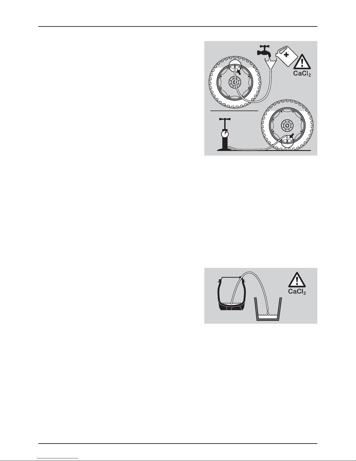
4 - Sprayer setup
47
Counter Weight
To improve stability on articulated models, extra weight can be added
by means of liquid-filled tyres.
The standard tyre valve is an universal air-water valve. The tyres may be
filled with liquid to max. 75% of their total volume.
Use a mixture of water and CaCl
2
(calcium chloride) to avoid frost
damage as described below:
200 g CaCl
2
per litre of water gives protection to -15 °C.
300 g CaCl
2
per litre of water gives protection to -25 °C.
435 g CaCl
2
per litre of water gives protection to -35 °C.
Filling the tyres
1. Jack up the wheel and rotate wheel till the valve is positioned at
“12 o’clock”.
2. Remove the valve body and fill liquid, until it reaches the valve.
3. When surplus liquid is drained through the valve stem, fit the valve
body again.
4. Adjust tyre pressure and lower the wheel. Please refer to “Tyre
Pressure” on page 106.
€
DANGER! It is very important that the CaCl2 is added to the water and agitated, until it is fully dissolved. Never pour
water on to CaCl
2
! If you get CaCl2 in your eyes, flush instantly with cold water for at least 5 minutes and seek medical
advice afterwards.
±
WARNING! The tyres must be liquid filled to max. 75 % of total tyre volume. Fill only the quantity. of liquid necessary
to obtain sufficient stability of the sprayer. Do not fill liquid and CaCl
2
mixture in tyres without tubes!
μ
ATTENTION! When filling the tyres, the valve should be positioned at 12 o’clock, and when adjusting the tyre pressure
the valve should be positioned at 6 o’clock.
Emptying the tyres
1. Rotate wheel until the valve is positioned at “6 o’clock”.
2. Remove the valve body and lead the liquid away. Retain the liquid
in an appropriate container.
3. To empty the tyre completely, the tyre is inflated and a thin drain
tube is led to the bottom of the tyre. The air pressure will now
empty the remaining liquid.
4. Remove the drain tube, fit the valve and inflate the tyre to specified
pressure. See “Technical Specifications” in the table “Tyre pressure”.
μ
ATTENTION! Disposal of CaCl2 has to take place according to local legislation.

4 - Sprayer setup
48
Brakes
Hydraulically Activated Brakes (optional)
This requires a special trailer brake valve attached to the tractor hydraulic
and brake system. Connect the snap coupler to the tractor brake outlet.
When the tractor brakes are applied, the trailer brakes will work
proportionally to the tractor brakes, and ensure safe and effective
braking.
±
WARNING! Do not connect the brakes directly to the tractor
hydraulics without the brake valve. The trailer brake power
cannot be controlled, and braking will therefore be hazardous.
±
WARNING! Maximum oil pressure is 150 bar in the brake line.

49
5 - Operation
General Info
Environmental Info
For environmental info, please refer to the following parts in the Spray Technique Book:
• Nozzles.
• Spray quality.
• Choosing nozzles for arable crops.
• Spraying speed.

5 - Operation
50
Boom
Safety Info
The boom must not be folded/unfolded while driving! Never use the folding/unfolding functions before the sprayer has
been stopped! Failure to do so will damage the boom.
€
DANGER! Before unfolding the boom it is important to connect the sprayer to the tractor to prevent overbalancing
of the sprayer.
€
DANGER! When folding or unfolding the boom, make sure that no persons or objects are within the operating area
of the boom.
€
DANGER! Always follow the guidelines listed below when driving in areas with overhead power lines:
Never use the folding/unfolding functions in areas with overhead power
lines.
Unintended boom movements may cause contact with overhead
power lines.
μ
ATTENTION! A label (ref. no. 978448) follows the sprayer. This label
must be placed in the cabin visible from the operator’s seat.
μ
ATTENTION! Only unfold and fold the boom on level ground.
Manoeuvring of the boom Y-version (only EAGLE Boom)
The Eagle boom with hydraulic Y-version is operated as follows:
1. Activate the single acting hydraulic outlet to raise the boom and release it from the transport brackets.
2. Activate the double acting hydraulic outlet to unfold the boom. Both wings will now unfold simultaneously.
3. When the boom is completely unfolded, it can be raised or lowered to the desired spray height by activating the single
acting hydraulic outlet.
4. Before attempting to fold the boom back into transport position, it must be raised all the way to the top by activating
the single acting outlet. This will enable the rear cylinder transport lock.
5. The boom is folded by activating the double acting outlet in the opposite direction as for unfolding the boom. The
boom can now be lowered into the transport brackets.
6. The rear cylinder transport lock will automatically engage when lowering the boom, after it has been raised all the way
to the top. To disengage the rear transport lock, simply raise the boom back up a few centimetres and then lower it
again.
μ
ATTENTION! Only unfold and fold the boom on level ground.
±
WARNING! Ensure that the pendulum lock is locked before using the fold functions.
±
WARNING! Ensure that the rear cylinder transport lock is properly engaged before transport.

5 - Operation
51
Manoeuvring of the boom (Z-version) with HC 5500
The switches on the hydraulic control box controls the following
functions:
1. Power ON/OFF
2. Pendulum lock
3. Boom tilt left
4. Boom lift raise/lower
5. Boom tilt right
6. Boom slanting
7. Boom outer folding left
8. Boom inner folding (both sides)
9. Optional function
10. Optional function
11. Manual track control (left/right) (optional)
12. Track control auto (manual/auto/lock) (optional)
13. Boom outer folding right
±
WARNING! Ensure that the pendulum lock is locked before using the fold functions.
±
WARNING! Ensure that transport safety chains are removed and the boom is clear from the transport brackets before
unfolding.
±
WARNING! The folding functions must only be operated when the sprayer is stationary! Failure to do so will damage
the boom.
μ
ATTENTION! The boom can not be operated with the tractors hydraulic levers.
For unfolding of the boom then do the following:
1. Check that pendulum (2) is locked.
2. Push switch (4) upwards to lift the boom clear of the front transport brackets.
3. Push switch (8) downwards to unfold the inner sections. Rear transport hooks disengage automatically.
4. Push switches (3) and (5) downwards to lower the individual tilt rams.
5. Push switch (7) to the left and (13) to the right to unfold outer sections.
6. Push switch (6) to correct slant angle.
7. Push switch (4) downwards to lower the boom to correct height above crop or ground level.
8. Unlock pendulum (2).
For folding of the boom then do the following:
Push switch (6) to set neutral slant angle (no slant). Check that pendulum (2) is locked.
Push switch (4) upwards to raise the boom to highest possible position.
Push switch (7) to the right and (13) to the left to fold outer sections.
Push switches (3) and (5) upwards to raise the individual tilt rams.
Push switch (8) upwards to fold the inner sections. Make sure to fold the inner sections against the vertical slide pads. Push
switch (4) downwards to lower the boom until the rear transport hooks are firmly engaged.
Push switches (3) and (5) downwards to lower the individual tilt rams until they rest on the front transport brackets.
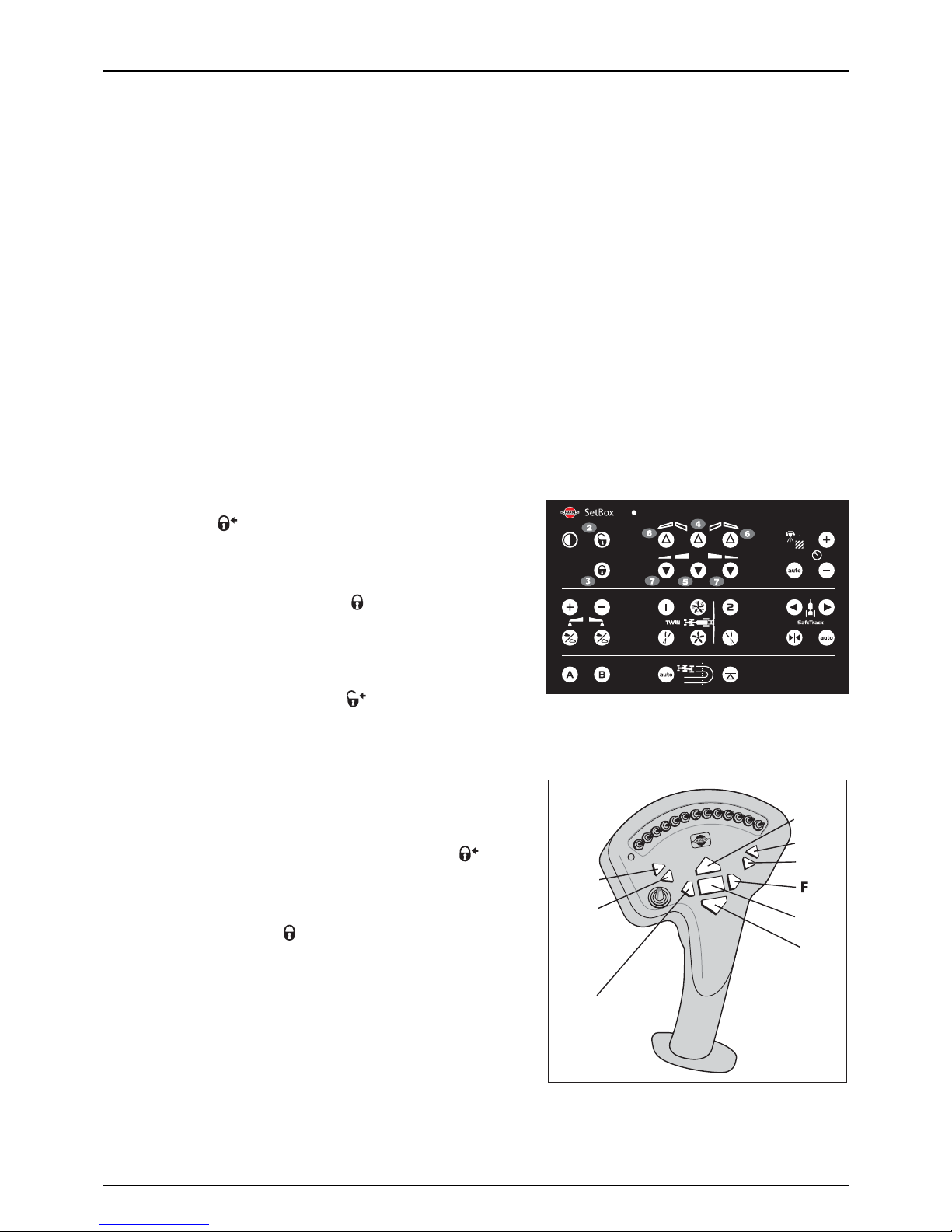
5 - Operation
52
Manoeuvring of the Boom (Z-version) with HC 6500 / HC 8500 / HC 9500 / ISOBUS
±
WAR NING!
The pendulum lock automatically turns ON, when pressing one of the folding buttons. Boom folding is not
possible, if the pendulum is unlocked. A manual override of the pendulum lock is possible by activating buttons 2 or 3.
±
WARNING! Ensure that transport safety chains are removed, and that the boom is clear from the transport brackets,
before unfolding.
±
WARNING! The folding functions must only be operated, when the sprayer is stationary! Failure to do so will damage
the boom. The pendulum lock automatically opens at speeds exceeding 1.5 km/h!
μ
ATTENTION! The boom cannot be operated with the tractors hydraulic levers.
μ
ATTENTION! Only buttons relevant for boom functions are described here. Refer to the instruction book for SetBox for
descriptions of other buttons.
To unfold th e b o om
±
WARNING! The pendulum lock automatically opens when you begin to drive. Drive slowly until the pendulum is
completely unlocked.
1. Push the lift up button (H) to lift the boom clear of the transport
brackets. The symbol appears in display until pendulum is
locked. This takes approximately 10 seconds.
2. Push the button (5) to unfold the inner wings completely. This
takes approximately 5 seconds, or a warning will appear. Check
that the pendulum locked symbol is visible in the display.
3. Push the buttons (7) to unfold the first outer wings.
4. Push the lift down button (I) to lower the boom to the correct
working height.
5. If not unlocked, then press (2) and symbol appears in display
until pendulum is unlocked. This takes approximately 10 seconds.
To fold th e b oom
1. Push slant buttons (E) or (F) to set neutral slant angle (no slant).
2. Push lift up button (H) to raise the boom to the highest possible
position.
3. Push the buttons (6) to fold the first outer wings. The symbol
appears in display until pendulum is locked. This takes
approximately 10 seconds.
4. Push the button (4) to fold the inner wings. Check that the
pendulum lock symbol is visible in the display.
5. Push the lift down button (I) to lower the boom, until it rests in the
paralift locks.¨
6. Push tilt down buttons (B) and (D) to lower the individual tilt rams,
until they rest on the front transport brackets.
A
B
C
D
E
H
G
I

5 - Operation
53
Hydraulic Slanting Control (Optional)
Boom, Z-version
The hydraulic boom slanting control enables slanting of the entire boom. This is advantageous when spraying across
hillsides.
Reset position to neutral (midway) before folding the boom.
Boom, Y-version
Use the tractor’s hydraulic lever to slant the entire boom.
Reset position to neutral (midway) before folding the boom.
Boom Tilt Function (Z-version only)
The boom tilt function controls enables you to adjust the boom height individually in the right and left hand side.
HC 6500
Boom tilt function controls (A), (B), (C) and (D) on the Grip.
HC 5500
Boom tilt function controls are on the Hydraulic box.
Alternative boom width
The spray working width can be changed, a 2-folded boom can be folded to half width, and a 3-folded boom can be folded
to either half width or 2/3 width.
To do this, unfold the inner section by pressing switch(6) downward. Remember to turn off the outer section valves on the
spray control box.
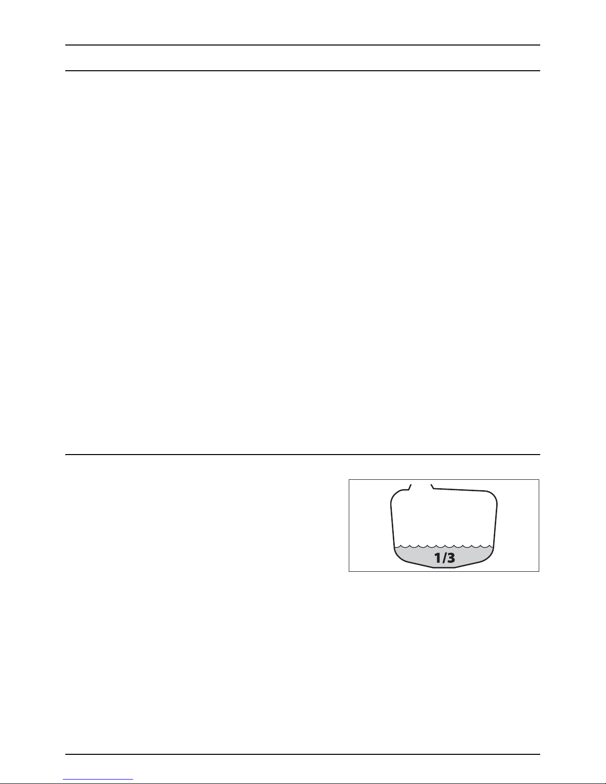
5 - Operation
54
Liquid System
Filling/Washing Location Requirements
When filling the sprayer with chemicals and water, it is important to avoid spot contamination by spraying chemicals in
order to protect the subsoil water resources.
A. If the sprayer is always filled on the same location, a special filling/washing location should be established. This should
have a hard, liquid-impenetrable surface (e.g. concrete), together with edges securing against run-off to the
surrounding areas. The location should be drained to an adequate receptacle (e.g. slurry tank or similar).
Any spillage or washings should be retained and diluted in order to be distributed in a larger area. This is to ensure
minimal environmental impact and avoid build-up of larger chemical concentrations at one spot.
If no other requirements of distances exist, the following general recommendation of distance can be used. Filling
location must be no closer than:
1. 50 metres from public water supplies for drinking purposes, and
2. 25 metres from non-public water supplies for drinking purposes and from treatment sumps and cesspools of
drainage systems, and
3. 50 metres from surface water (watercourses, lakes and coastal waters) and from nature reserves.
D. Alternatively the sprayer can be filled in the field, where the spraying is to take place. If so, choose a different location
for each refilling.
If no other requirements of distances exist, the filling should not take place closer than:
1. 300 metres from public or non-public water supplies for drinking purposes, and
2. 50 metres from surface water (watercourses, lakes and coastal waters), treatment sumps, cesspools of drainage
systems, and nature reserves.
μ
ATTENTION! Legislation and requirements vary from country to country. Always follow local legislation in force at any
time.
÷
NOTE! It is the responsibility of the sprayer owner/operator to comply with all relevant legislation. HARDI cannot
undertake any responsibilities for incorrect operation and use.
Filling of Water
The tank should normally be filled 1/3 with water before adding
chemicals. Always follow the instructions given on the chemical
container!
±
WARNING! If the sprayer is put aside with liquid in the main tank,
all manifold valves must be closed.
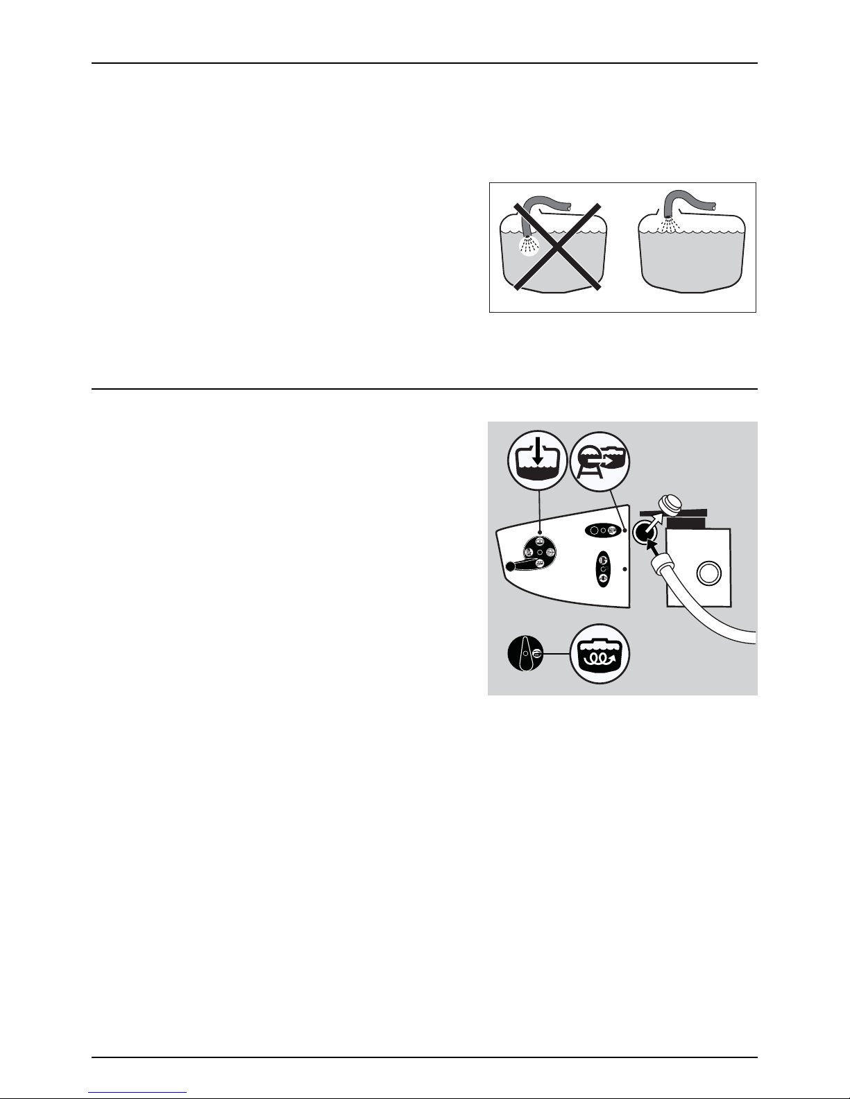
5 - Operation
55
Filling Through Tank Lid
Water is filled into the tank by removing the big tank lid, which is located at the top of the sprayer tank near the front, which
is accessible from the platform. It is recommended to use as clean water as possible for spraying purposes. Always fill water
through the strainer basket to prevent foreign particles from entering the tank. An overhead tank can be used in order to
obtain high filling capacity.
±
WARNING! Do not let the filling hose enter the tank. Keep it
outside the tank, pointing towards the filling hole. If the hose is
led into the tank, and the water pressure drops at the water
supply plant, chemicals may be sucked back and contaminate
the water supply lines, supply plant and supply well.
±
WARNING! The water supply line should be provided with a check
valve as additional safety precaution. Follow local legislation in
force at any time.
±
WARNING! The water supply should be provided with a water meter to avoid spillage by over-filling. Follow local
legislation in force at any time.
External Filling Device (optional)
The External Filling Device is operated as follows:
1. Remove cover and connect suction hose to Suction Manifold.
2. Turn pressure SmartValve to “Main tank”.
3. Turn handle on External Filling Device valve towards Filling Device.
4. Engage diaphragm pump and set PTO revolutions at 540 rpm.
5. The tank is now filled with water. Keep an eye on the liquid level
indicator.
6. Turn handle on Suction Manifold away from Filling Device to
discontinue filling process. Then disengage pump.
7. Disconnect suction hose and replace cover.
€
DANGER! Avoid contamination or personal injury. Do not open
suction valve towards Suction Filling Device, unless the pump is
running and the filling hose is connected. If this valve is opened
without the pump running, liquid will stream out of the coupler.
±
WARNING! Do not leave the sprayer whilst filling the tank, and keep an eye on the level indicator in order NOT to
overfill the tank.
±
WARNING! If suction hose/filter is carried on the sprayer during spraying, it can be contaminated by spray drift which
will be transferred to lake/river when filling!
μ
ATTENTION! Observe local legislation regarding use of filling device. In some areas, it is prohibited to fill from open
water reservoirs (lakes, rivers etc.). It is strongly recommended only to fill from closed reservoirs (mobile water tanks
etc.) to avoid contamination.

5 - Operation
56
Filtered Fast Fill System
The ‘Filtered Fast Fill’ allows the operator to fill the sprayer from an
external water source (such as a dam or tank) using an auxiliary
pump. The system includes a Cam-Lock coupling on the inlet and a
high capacity in line filter.
1. Remove the cover from the Cam-Lock coupling (A) and connect
a hose being fed from an auxiliary pump and external water
source.
2. Run the auxiliary pump and engage the Quick-Fill ball valve (B)
to fill.
3. Watch the tank level indicator closely to prevent over filling.
4. To stop filling close the Quick-Fill ball valve (B), turn off the
pump, disconnect the hose and replace the Cam-lock coupling
dust cover.
μ
ATTENTION! The optional flow meter is only available on
sprayers with the “Quick-Fill” system and is not offered on
machines with venturi or Banjo pump fast fill systems.
±
WARNING! Do not leave the sprayer while filling the tank and watch the level indicator closely to prevent over filling..
μ
AT TE NT IO N! Due to risk of contamination it is prohibited in some areas to fill a sprayer from open water ways such as
lakes and rivers etc. Contact your local authorities for information about laws specific to your area.
Directional fill valve (optional)
The Filtered Fast Fill System can by equipped with a “Directional Fill
Valve“(C). By turning the valve system can be used to fill either “Main
Tank” or “Rinse Tank”. The operator can control the speed at which
filling takes place by adjusting the quick fill ball valve on the sprayer.

5 - Operation
57
Banjo Filtered Fast Fill System
The ‘Banjo Filtered Fast Fill’ system employs a high capacity
centrifugal pump (P) driven by a hydraulic drive motor (M). The motor
is powered by the tractors auxiliary hydraulics and Speed limited by a
hydraulic burst valve. The operator can control the flow rate of the
pump by use of a variable
speed control valve (C) located on a panel
just forward of the filter.
μ
ATTENTION! Do not attempt to run the pump over the
recommended Maximum speed.
Operation
To fill the sprayer using the ‘Banjo” fast fill system:
1. Park the tractor and sprayer on a level surface, select neutral
gear, apply the hand brake and engage the auxiliary hydraulics.
2. Remove the cover from the Cam-lock coupling (A) and connect
a suction hose to a water source.
3. Open the ball valve (B) and gradually engage the hydraulic
speed control valve (C) until the desired flow rate is achieved.
4. When filling is complete dis-engage the hydraulic speed
control (C) and close the ball valve (B).
5. Remove the suction hose and replace the cam-lock cap (A).
A
B
C

5 - Operation
58
Filling of Rinsing Tank
The rinsing tank is filled via the 1” threaded connection piece at the valve system:
1. Remove the filler cap, then fit the external water hose to the threaded connection piece.
2. Engage external water pump, if any.
3. Keep an eye on the level indicator in order not to overfill the tank.
4. Stop filling and refit the cap.
Volume: approximately 450 litres.
μ
ATTENTION! Only fill rinsing tank with clean water! To avoid algae developing in the rinsing tank, always drain this
tank, if the sprayer is not in use for a longer period of time.
μ
ATTENTION! For cleaning purposes etc. the rinsing tank is also accessible via the tank lid on top of the tank.
Filling of Clean Water Tank
To fill the clean water tank:
1. Remove the tank lid
2. Fill with clean water
3. Reposition the tank lid.
For use of water:
• Turn the ball valve lever to open. The ball valve is located on the
valve cover.
The water from this tank is for hand washing, cleaning of clogged nozzles etc.
μ
ATTENTION! Only fill this tank with clean water! To avoid algae developing in the clean water tank, always drain this
tank, if the sprayer is not in use for a longer period of time.
±
WARNING! Although the clean water tank is only filled with clean water, this water must NOT be used for drinking.

5 - Operation
59
Safety Precautions - Crop Protection Chemicals
Always be careful when working with crop protection chemicals!
±
WARNING! Always wear proper protective clothing before handling chemicals!
Personal protection
Depending on chemical type, protective gear/equipment should be worn to avoid contact with the chemicals, such as:
• Gloves
• Waterproof boots
• Headgear
• Respirator
• Safety goggles
• Coverall with chemical resistance
±
WARNING! Protective clothing/equipment should be used, when preparing the spray liquid, during the spray job and
when cleaning the sprayer. Follow the chemical manufacturer’s instructions given on the chemical label and/or local
legislation.
±
WARNING! It is always advisable to have clean water available, especially when filling the sprayer with chemicals.
±
WARNING! Always clean the sprayer carefully and immediately after use.
±
WARNING! Only mix chemicals in the tank according to directions given by the chemical manufacturer.
±
WARNING! Always clean the sprayer before changing to another chemical.
Filling Chemicals through Tank Lid
The chemicals are filled through the tank lid - Note instructions on the chemical container!
±
WARNING! Be careful not to slip or to splash chemicals, when carrying chemicals up to the tank lid!
μ
ATTENTION! Due to risk of spillage and spot contamination, several countries do not allow to fill chemicals directly
through the tank lid. Use the TurboFiller for all filling of chemicals instead.
1. Make sure the spray control unit is switched off.
2. Set suction valve towards “Suction from main tank”, Agitation
valve towards “Agitation”. Turn pressure SmartValve towards
“Spraying”.
3. Engage the pump and set PTO revolutions to 540 rpm.
4. Add the chemicals through the main tank hole.
5. Keep PTO engaged, so that the spray liquid is continuously
agitated, until it has been sprayed on the crop.
€
DANGER! Before turning Pressure SmartValve past “Hopper, it
is very important to ensure that the quick coupler lid is
correctly and completely mounted to the filling stud in its
locked position. Failure to do so causes a risk of contamination and injury from the quick coupler lid being “shot” off
when pressurized! If it is not possible to mount the lid completely, lubricate the rubber seal and the grip hooks.
÷
NOTE! Local legislation may not allow filling through the tank lid, but will require use of the chemical inductor instead.

5 - Operation
60
Chemical Filling by VACnMIX (optional)
The VACnMIX chemical induction can be carried out in any one of the three following methods;
1. Induction of Dry Granules, Powders or Flowables by adding product to VACnMIX hopper.
2. Induction of Liquids by adding product to VACnMIX.
3. Using the optional Vacuum Feature to add Liquid Chemicals from Envirodrums
and other containers.
Filling the VACnMIX with water
Engage the pump. Set at 540 or 1000 rpm, relevant to equipped
pump.
1. Fill the main tank at least 1/3 with water (unless otherwise stated
on the chemical container label).
2. Engage the pump. Set at 540 or 1000 rpm, relevant to equipped
pump.
3. Set Vacuum and Transfer Valve to Fill position
4. Turn the Pressure Valve on your sprayer toward the Pressure
Hopper icon. This will allow you to activate the VACnMIX system.
5. On the VACnMIX controls, turn Fast Fill handle on, to fill hopper.
Watch the level of water. Fill to the 25 Litre level, which will be
just above the upper jet. (NOTE: Sight gauge is a guide only to
fluid volume in hopper).
6. When sufficient water is in the hopper turn Fast Fill handle off.
μ
Check operation by briefly operating all valves before introducing any chemical product. Check for leaks that may
indicate loose fittings, faulty valves or damaged hoses.
€
Do not use faulty equipment.
ON
FILL

5 - Operation
61
Filling with liquid or granular chemicals by VACnMIX (optional equipment)
±
WARNING! Only compatible and complimentary chemicals should be mixed. When combined, incompatible
chemicals may cause a potentially dangerous reaction, or result in unwanted effects on the crop to be sprayed.
ALWAYS follow label instructions!
1. Fill the hopper with water to the 25 litre level.
μ
ATTENTION! The scale in the hopper can only be used if the
sprayer is parked at level ground! It is recommended to use a
measuring jug for best accuracy.
2. Start a swirling action in the hopper by turning ON the upper
and lower jet handles and turning Off the Fast Fill handle.
3. Pour pre-measured chemical amount into vortex stream (not
into centre of hopper). Vortex action will be reduced during the
addition of chemical.
÷
NOTE! Large unmixed chemical will be held by centrifugal
force to the outside wall of the hopper. Continue mixing in the
hopper until chemical is fully integrated into water.
÷
NOTE! Always ensure that enough pressure is maintained to
drive the vortex. A drop in level may cause air to enter the
suction line, and too high a level will cause slowing of the vortex, resulting in incomplete mixing of chemicals which
may affect the accuracy of application rates when spraying.
4. When all chemical has been thoroughly mixed, close vortex jet
handles.
5. To transfer the mixture to the sprayer tank. Close lid of VACnMIX,
turn the Vacuum Transfer Valve to the EMPTY position. This will
allow a venturi to create a vacuum inside the VACnMIX and
allow the hopper contents to flow through to the main tank.
6. With the lid still closed, flush the hopper using the hopper rinse
ring between batches of chemical.
7. After all chemicals have been added to the sprayer tank, and the
VACnMIX is empty, set the suction ball valve on the sprayer
manifold to Flush Tank in order to flush the VACnMIX system
with clean water.
8. Refill the hopper with clean water, operate all valves as in mixing
procedure, empty and repeat until the system is clear of residue
chemical.
ON /
OFF
FILL

5 - Operation
62
Filling chemicals by VACnMIXs Chem Probe
÷
NOTE! Before adding any chemicals, fill hopper with water to
test functions see “Filling the VACnMIX with water” on
page 60.
1. Connect Chem Probe camlock to Ball Valve on VACnMIX, OR
Connect suction hose to the camlock fittings on the ball valve
of the hopper and the Drum coupling.
2. With lid of VACnMIX closed, turn the Vacuum and Transfer Valve
to FILL position
3. The vacuum is controlled by the ball valve and vent. In the
CLOSED (A) position,the ball valve is open to the suction line,
and liquid chemical will be drawn from the drum into the
hopper.
4. To stop the flow of liquid chemical from the drum, move the ball
valve to OPEN (B) position - this allows air from the atmosphere
to be introduced to the hopper through the vent, and closes off
the suction line.
5. To transfer measured volume of chemical mixture to the sprayer
tank, turn the Vacuum and Transfer valve to EMPTY.
6. Flush Hopper and Sight Tube between different chemicals.
μ
ATTENTION! The hopper rinsing devices use spray liquid for
rinsing the hopper. The VACnMIX must always be
cleaned/decontaminated together with the rest of the sprayer
with fresh water when the spray job is complete.
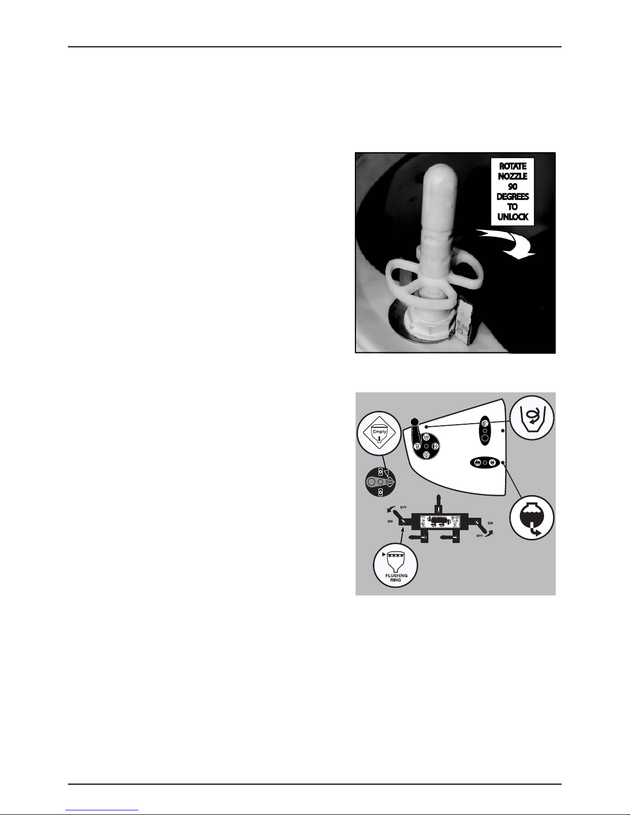
5 - Operation
63
VACnMIX Rinsing
÷
NOTE! It is important to suck from the rising tank or an external tank with clean water.
Rinse the VACnMIX and chemical containers as follows:
Cleaning empty containers - VACnMIX lid open
€
DANGER! Do not press the nozzle unless it is covered by a
container to avoid spray liquid hitting the operator.
1. Rotate the nozzle 90 degree to unlock
1. Put container over the flushing nozzle so that the nozzle is
inside the container and press bottom against the nozzle, this
will force a powerful jet of water up into the inside of the
container.
÷
Note: This lock acts as a safety measure to prevent injury to
operator. Ensure lock is repositioned correctly after use.
VACnMIX rinsing - VACnMIX lid is closed
1. Close VACnMIX lid.
2. Turn the suction SmartValve towards “Rinsing tank” or “External
Filling Device”, if clean water is available here.
3. Turn the Vacuum and Transfer Valve to FILL position.
4. Flush the hopper using the rinse valve. Control the rinse by
turning flush ring handle on VACnMIX control manifold to the
ON / OFF position.
5. Rinse the hopper for 30-40 second or more if needed.
6. Turn the Vacuum and Transfer Valve to EMPTY position, let valve
be open for at least 20 seconds, after the rinse water is no longer
visible in the hopper, in order to completely empty the transfer
hoses into the main tank.
μ
ATTENTION! The VACnMIX needs to be cleaned thoroughly
after finishing spraying. This is to ensure that it is clean, before
spraying other crops that may be sensitive to the chemicals
just used. See section “Cleaning” on page 71 for details.

5 - Operation
64
Filling Liquid Chemicals by using HARDI TurboFiller
÷
NOTE! We advice to use the TurboFiller, when you fill chemicals from an external tank.
1. Fill the main tank at least 1/3 with water (unless otherwise
stated on the chemical container label).
2. Turn the handle of the suction valve towards “suction from Main
tank”. Turn pressure SmartValve towards “Pressure Hopper”.
Close the AgitationValve.
÷
NOTE! If filling water from an external tank, this can be
continued while doing the next steps.
€
DANGER! Before turning Pressure SmartValve to “Pressure
Hopper” it is very important to be sure that the quick coupler
lid is correct and completely mounted to the filling stud into
its locked position. Failure to do so may cause risk of
contamination and injury from quick coupler lid being “shot” off when pressurized! If not possible to mount lid
completely, lubricate the rubber seal and the grip hooks.
3. Engage the pump and set PTO speed at 540 rpm or 1000 rpm (depending on pump model).
4. Open TurboFiller lid. Measure the correct quantity of chemical and fill it into the hopper.
€
DANGER! Always wear face shield and other appropriate personal safety equipment, when filling chemicals.
μ
ATTENTION! The scale in the hopper can only be used, if the sprayer is parked on level ground! It is recommended to
use a measuring jug for best accuracy.
5. Engage the hopper transfer device by opening the TurboFiller suction valve to transfer chemicals to the main tank.
The TurboFiller suction valve must be open for at least 20 seconds after the chemical is no longer visible in the hopper,
in order to empty the transfer hoses completely into the main tank.
€
DANGER! If the TurboFiller and the transfer hoses are not completely emptied, there is a risk of chemicals being
sucked out of the main tank!
6. If the chemical container is empty, it can be rinsed by the Chemical Container Cleaning device. Place the container
over the multi-hole nozzle and push the container for cleaning.
€
DANGER! In order to avoid spray liquid hitting the operator, do not press the lever, unless the multi-hole nozzle is
covered by a container, as spray liquid may otherwise hit the operator!
μ
ATTENTION! The rinsing device uses spray liquid to rinse containers for concentrated chemicals. Before disposal,
always rinse the chemical containers with clean water several times, until they are clean.
7. Flush the TurboFiller with clean water from the rinsing tank. The TurboFiller suction valve must be open for at least 20
seconds after the rinse water is no longer visible in the hopper, in order to empty the transfer hoses completely into
the main tank.
μ
ATTENTION! If not flushed with clean water, the hopper rinsing device uses spray liquid for rinsing the hopper!
Cleaning the TurboFiller must always be done, when the spray job is ended, and together with cleaning the entire
sprayer. A cleaning after the last filling, and before spraying, does not ensure a clean TurboFiller!
8. Close the TurboFiller suction valve, when the hopper has been rinsed. Close the lid.
9. Turn the AgitationValve towards “Agitation”.

5 - Operation
65
10. When the spray liquid is well agitated, turn handle of the
pressure SmartValve towards “Spraying” position. Keep PTO
engaged, so that the spray liquid is continuously agitated, until
it has been sprayed on the crop.
Filling Powder Chemicals by using HARDI TurboFiller
1. Fill the main tank at least 1/2 with water (unless otherwise
stated on the chemical container label). See section “Filling of
water”.
2. Turn the handle of the suction valve towards “suction from Main
tank”. Turn pressure SmartValve towards “Pressure Hopper”.
Turn the AgitationValve towards “Agitation” if required. Close
remaining valves.
μ
ATTENTION! For increased suction from the TurboFiller the
AgitationValve can be kept closed.
÷
NOTE! If filling water from an external tank, this can be
continued while doing the next steps.
€
DANGER! Before turning Pressure SmartValve to “Pressure to hopper” it is very important to be sure that the quick
coupler lid is correct and completely mounted to the filling stud into its locked position. Failure to do so may cause
risk of contamination and injury from the quick coupler lid bei ng “shot ” of f when pressuri zed! I f not p ossib le to m ount
lid completely, lubricate the rubber seal and the grip hooks.
3. Engage the pump and set PTO speed at 540 rpm or 1000 rpm (depending on pump model).
4. Open TurboFiller lid. Open TurboDeflector valve and TurboFiller suction valve.
5. Measure the correct amount of powdered chemical and sprinkle it into the hopper as fast as the transfer device can
flush it down. The TurboFiller suction valve must be open for at least 20 seconds after the chemical is no longer visible
in the hopper in order to completely empty the transfer hoses into the main tank.
€
DANGER! If the TurboFiller and the transfer hoses are not completely emptied, there is a risk of chemicals being
sucked out of the main tank!
€
DANGER! Always wear face shield and other appropriate personal safety equipment, when filling chemicals.
6. If the chemical container is empty, it can be rinsed by the Chemical Container Cleaning device. Place the container
over the multi-hole nozzle and push the upper lever to the left of the TurboFiller.
€
DANGER! In order to avoid spray liquid hitting the operator, do not press lever unless the multi-hole nozzle is covered
by a container, as spray liquid may otherwise hit the operator!
μ
ATTENTION! The rinsing device uses spray liquid to rinse containers for concentrated chemicals. Always rinse the
chemical containers with clean water several times, until they are clean before disposal.
7. Flush the TurboFiller with clean water from the Rinsing tank. The TurboFiller suction valve must be open for at least 20
seconds after the rinse water is no longer visible in the hopper, in order to completely empty the transfer hoses into
the main tank.
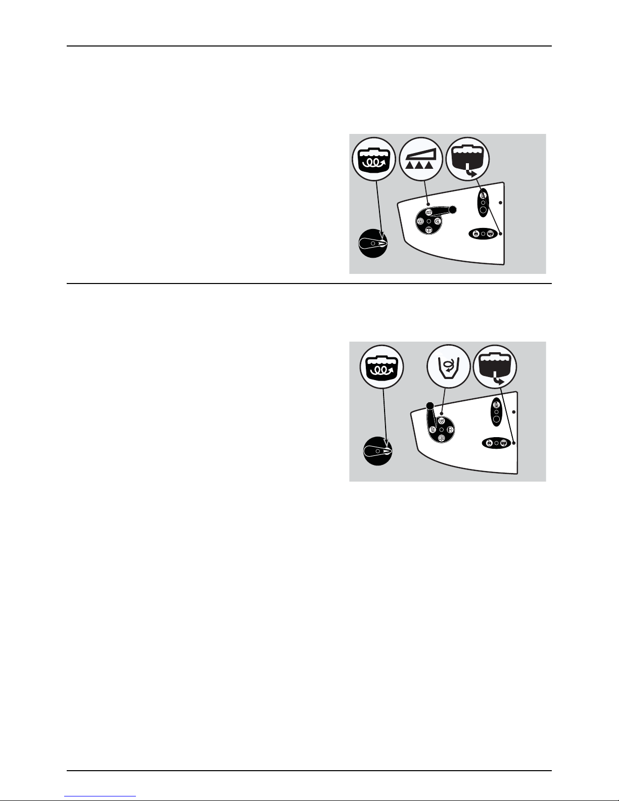
5 - Operation
66
μ
ATTENTION! If not flushed with clean water, the hopper rinsing device uses spray liquid for rinsing the hopper!
Cleaning the TurboFiller must always be done, when the spray job is ended, and together with cleaning the entire
sprayer. A cleaning after the last filling, and before spraying, does not ensure a clean TurboFiller!
8. Close TurboFiller suction valve, when the hopper has been rinsed. Close the lid.
9. If closed, turn the AgitationValve towards “Agitation”.
10. When the spray liquid is well agitated, turn handle of the
pressure SmartValve towards “Spraying” position. Keep PTO
engaged, so that the spray liquid is continuously agitated, until
it has been sprayed on the crop.
Agitation before Resuming a Spray Job
If a spray job has been interrupted for a while, severe sedimentation may occur depending on the chemicals being used.
Before resuming the spray job, it might be necessary to agitate sediment material.
1. Turn the handle at the suction valve towards “Suction from
main tank”. Turn the pressure alve towards “Pressure Hopper”
and turn the Agitation valve towards “Agitation”. Other valves
closed.
2. Engage the pump and set PTO speed to 540 rpm or 1000 rpm
(depending on pump model).
3. Agitation has started and should be continued for at least 10
minutes.
4. The spray job can now be resumed. Turn pressure SmartValve
towards “Spraying” and start spraying.
€
DANGER! Before turning Pressure SmartValve to “Pressure
Hopper” it is very important to be sure that the quick coupler lid is correct and completely mounted to the filling stud
into its locked position. Failure to do so may cause risk of contamination and injury from quick coupler lid being “shot”
off when pressurized! If not possible to mount lid completely, lubricate the rubber seal and the grip hooks.
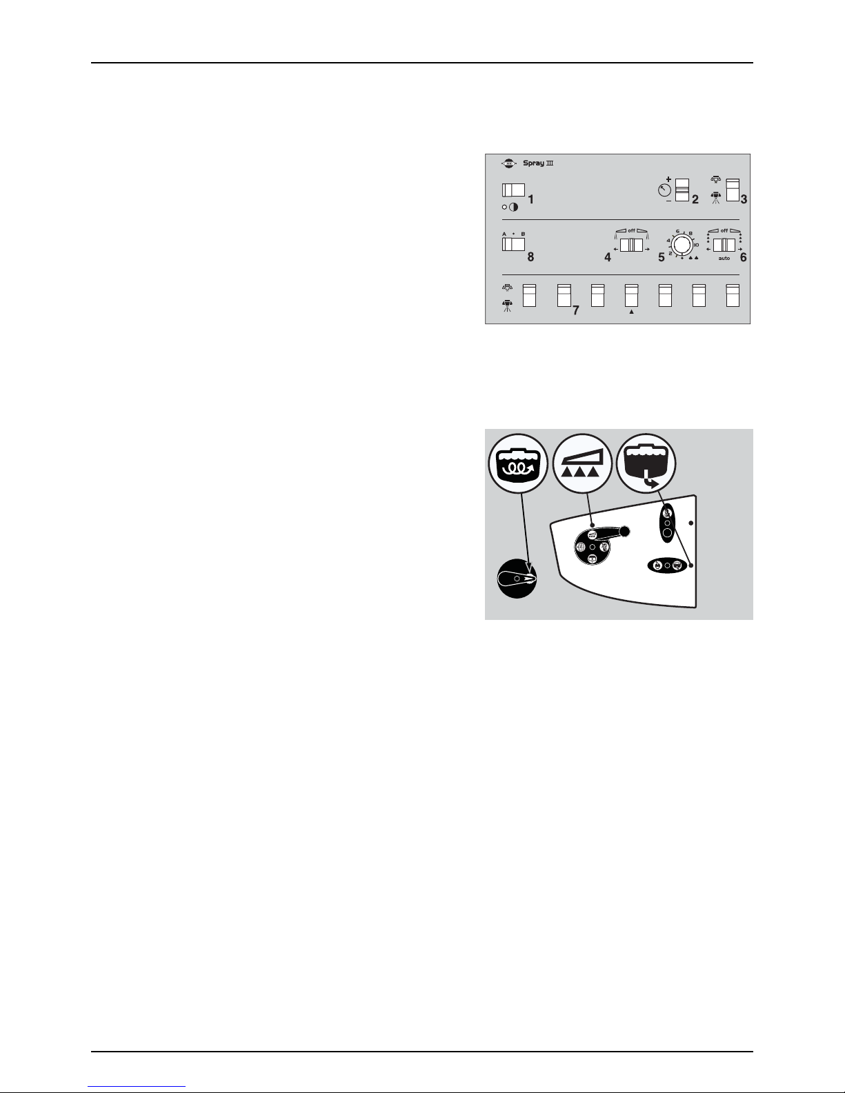
5 - Operation
67
Operating the control unit while spraying (Z-version) HC 5500
μ
ATTENTION! The following information is intended as a general guide only. For detailed information please refer to
the Controller HC 5500 / Spray Box III manual, supplied with your sprayer.
The switches of the spray control unit control the following functions:
1. Power ON/OFF. Turns the spray box power on or off.
2. Spray pressure regulation. Regulates the main spray pressure.
3. Main valve ON/OFF. Turns all sections on or off. Lever up is OFF and
down is ON.
4. End nozzle (Left/OFF/Right). If end nozzles are fitted, they can be
turned on for each side. Middle position is OFF.
5. Foam marker blob interval. Regulates the blob interval for the
optional foam marker.
6. Foam marker (Left/OFF/Right). Turns the optional foam marker on for each side. Middle position is OFF.
7. Section valves. Turns single sections on or off. Lever up is OFF and down is ON.
8. Optional function (A/OFF/B). If extra equipment is added, it can be controlled from here. Middle position is OFF.
• In order to close the entire boom, switch main ON/OFF (3) to OFF
position. This returns the pump output to the tank through the
return system. The diaphragm Non-drip valves ensure
instantaneous closing of all nozzles.
• In order to close one or more sections of the boom, switch the
relevant distribution valve (7) to off position (upwards). The
pressure equalisation ensures that the pressure does not rise in the
sections that remain open.
On the sprayer the suction valve should be turned toward “Suction from
Main tank” and the pressure SmartValve should be turned toward
“Spraying”. Turn the agitation valve to “Agitation” if necessary.

5 - Operation
68
Operating the control units while spraying (Z-version) HC 6500 / HC 8500 / HC9500 / ISOBUS
μ
ATTENTION! The following information is intended as a general guide only. For detailed information regarding HC
6500 / HC 8500 / HC 9500 / ISOBUS please refer to the specific manual supplied with your sprayer.
The control units control the following spray functions:
1. Power ON/OFF/status LED. LED must be ON.
2. Automatic spray pressure regulation.
The regulation valve controls the main spray pressure. This is
default selection when the controller is powered ON, and it should
remain here during normal spraying.
3. Manual spray pressure regulation. Under normal spraying these
should not be used as the regulation valve does this automatically.
4. Foam marker blob interval. Regulates the blob interval for the
optional foam marker.
5. Foam marker (Left/Right). Turns the optional foam marker ON for
each side.
6. Optional function (A/B). If extra equipment is added, it can be controlled from here.
A. Power ON/OFF/status LED. LED must be ON.
B. Section valves. Turns single sections on or off. Lever up is OFF and
down is ON.
C. Main valve ON/OFF.
Use when spraying
• On the sprayer, turn the suction valve toward “Suction from
Main tank” and the pressure SmartValve toward “Spraying”. Turn
the agitation valve to “Agitation” if necessary.
• In order to close the entire boom, switch main ON/OFF (C) to
OFF position. This returns the pump output to the tank through
the return system. The diaphragm Non-drip valves ensure
instantaneous closing of all nozzles.
• In order to close one or more sections of the boom, switch the
relevant distribution valve (B) to OFF position (upwards). The
pressure equalisation ensures that the pressure does not rise in
the sections that remain open.
÷
NOTE! For checking the volume application rate, please refer
to the spray controller instruction book.
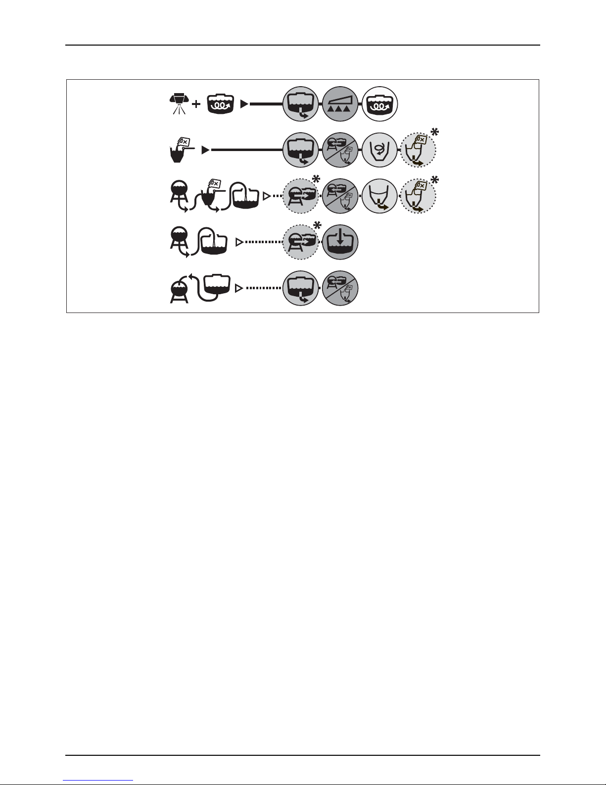
5 - Operation
69
Quick reference - Operation
In the following diagrams handle positions for different options are described.
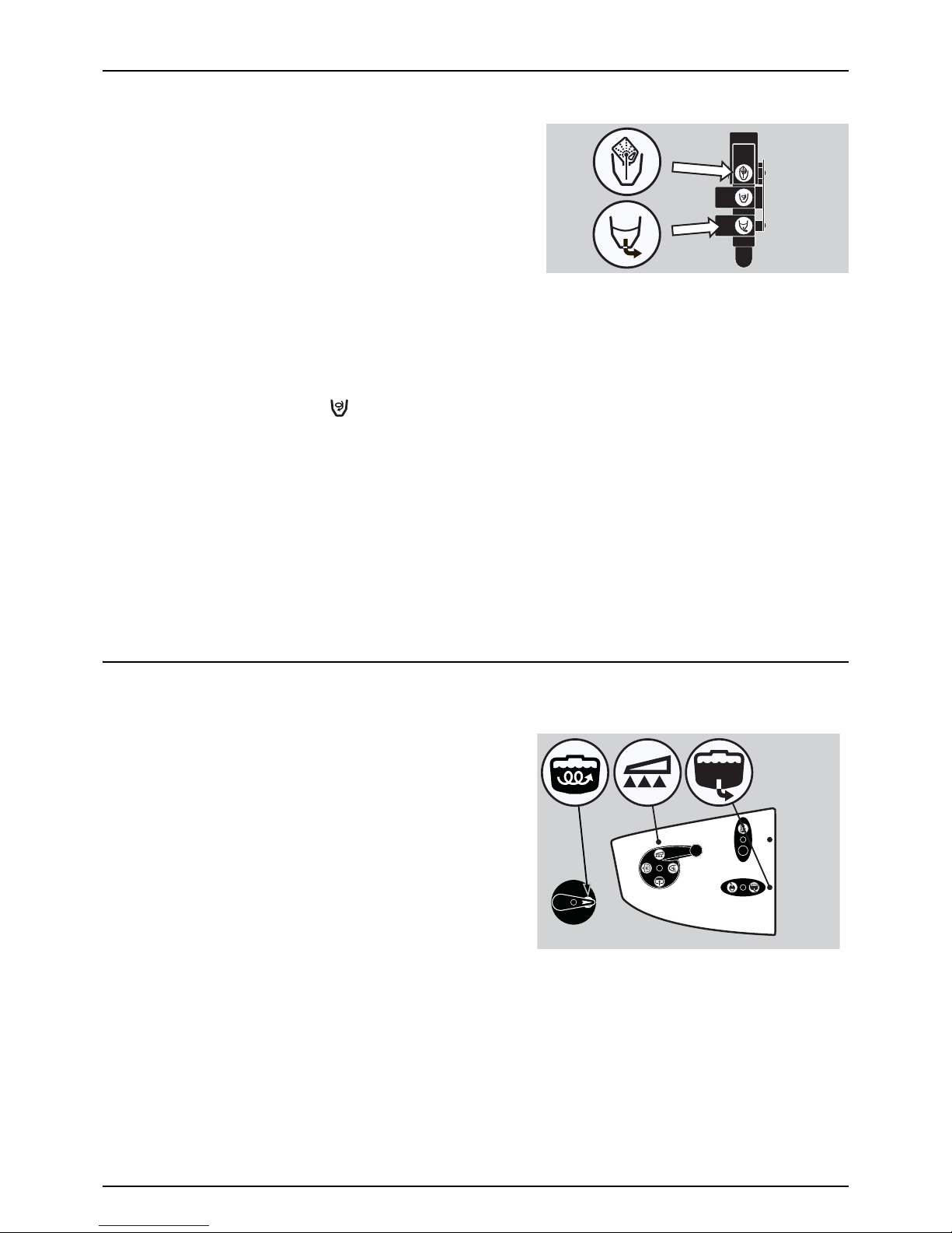
5 - Operation
70
TurboFiller Rinsing
÷
NOTE! It is important to suck from the rising tank or an external
tank with clean water.
Rinse the TurboFiller and chemical containers as follows:
Cleaning empty containers - TurboFiller lid is open
1. Put container over the rotating flushing nozzle in the middle of the
TurboFiller, so that the nozzle is inside the container.
2. Simultaneously press the Chemical Container Cleaning lever and
the TurboFiller suction valve. This rinses the chemical container
with the flushing nozzle, while the rinsing liquid is emptied out of the TurboFiller.
TurboFiller rinsing - TurboFiller lid is closed
1. Close TurboFiller lid.
2. Turn the suction SmartValve towards “Rinsing tank” or “External Filling Device”, if clean water is available here.
3. Open the Turbo Deflector Valve for 1 minute to get plenty of clean water through the hoses.
4. Simultaneously press the Chemical Container Cleaning lever and the TurboFiller suction valve. This rinses the hopper
with the flushing nozzle, while the rinsing liquid is emptied out of the TurboFiller.
5. Rinse the hopper for 30-40 seconds.
6. Open the lid to inspect if the TurboFiller is empty. If not, close the lid again and press the TurboFiller suction valve, until
the TurboFiller is empty.
7. After the last flushing, the TurboFiller suction valve must be open for at least 20 seconds, after the rinse water is no
longer visible in the hopper, in order to completely empty the transfer hoses into the main tank.
μ
ATTENTION! The TurboFiller needs to be cleaned thoroughly after finishing spraying. This is to ensure that it is clean,
before spraying other crops that may be sensitive to the chemicals just used. See section “Cleaning” on page 71 for
details.
BoomPrime (optional)
The BoomPrime system works automatically, and it is activated, when a spray job is prepared:
1. Unfold the boom and turn on the PTO.
2. Set pressure SmartValve to “Spraying”, suction valve to “Main
tank” and agitation valve to “Agitation”, if needed.
3. Adjust the spray pressure to what will be used when spraying.
4. The boom will then be fully primed within 1-2 minutes.
If the nozzles start to leak, when closing one or more sections during
a spray job, proceed as follows:
1. Adjust the pressure on the BoomPrime pressure regulation.
2. Turn Pressure SmartValve to “Main tank”.
3. Disconnect the PTO.
If adjustment of the BoomPrime system might be necessary, please refer to “BoomPrime Adjustment (optional)” on page 44.

5 - Operation
71
Cleaning
General Info
In order to derive full benefit from the sprayer for many years ,the following service and maintenance program should be
followed.
μ
ATTENTION! Always read the individual paragraphs. Read instructions for service/maintenance jobs carefully before
starting on the job. If any portion remains unclear, or if it requires facilities which are not available, then please leave
the job to your HARDI dealer’s workshop for safety reasons.
μ
ATTENTION!
Clean sprayers are safe sprayers.
Clean sprayers are ready for action.
Clean sprayers cannot be damaged by pesticides and their solvents.
Guidelines
1. Read the whole chemical label. Take note of any particular instructions regarding recommended protective clothing,
deactivating agents, etc. Read the detergent and deactivating agent labels. If cleaning procedures are given, follow
them closely.
2. Be familiar with local legislation regarding disposal of pesticides washings, mandatory decontamination methods, etc.
Contact the appropriate authority if you are in doubt.
3. Pesticide washings can usually be sprayed out on the field just sprayed or at a suitable cultivated area. Avoid emptying
the washings at the same spot every time and keep sufficient distance to the water environment. You must prevent
seepage or runoff of residue into streams, watercourses, ditches, wells, springs, etc. The washings from the cleaning
area must not enter sewers. Alternatively the washings can be retained in an appropriate receptacle, diluted and
distributed over a larger cultivated area - see also “Filling/Washing Location Requirements” on page 54.
4. Cleaning starts with the calibration, as a well calibrated sprayer will ensure the minimal amount of remaining spray
liquid.
5. It is good practice to clean the sprayer immediately after use, and thereby rendering the sprayer safe and ready for the
next pesticide application. This also prolongs the life of the components. It is strongly advised to perform an internal
cleaning of the sprayer, when high concentrations of acids or chloride are present in the active ingredients, or if the
spray liquid is corrosive. For the best result, use a cleaning agent recommended by HARDI, e.g. AllClearExtra.
6. It is sometimes necessary to leave spray liquid in the tank for short periods, e.g. overnight, or until the weather becomes
suitable for spraying again. Unauthorized persons, children and animals must not have access to the sprayer under
these circumstances.
7. If the product applied is corrosive, it is recommended to coat all metal parts of the sprayer before and after use with a
suitable rust inhibitor.
8. The sprayer must always be parked under roof to avoid rain washing off pesticides as well as build-up of spot
contamination in the soil. If parked outside, the sprayer should be parked on the filling/washing location in order to
retain possible pesticides.

5 - Operation
72
Quick Reference - Cleaning
÷
NOTE! Pump speed 250-280 rpm.
A. Turn On.
B. Turn Off.
C. Minimum 45 seconds with nozzle Off.
D. Spray until air comes out of nozzles. When pressure drops, close regulation valve by pressing the button, until
yellow LED lights on the valve. When the boom is completely empty, press the button for a few seconds to avoid
pressure spike.
Standard Cleaning
μ
ATTENTION! For cleaning between spray jobs where crops are not very sensitive towards chemicals just sprayed.
1. Engage pump with tractor in idle, so that pump speed is as low as possible (250/550 rpm, depending on pump type).
2. Turn suction valve towards and the pressure SmartValve towards while sucking approximately 1/6 of the
rinse tank content into the main tank. It is important to have full agitation for approximately 20 seconds, and then close
agitation valve completely.
3. Turn suction valve towards and the pressure SmartValve towards with all sections off for approximately 45
seconds.
4. Turn all sections on. Spray until air comes out of nozzles. When pressure drops, close regulation valve by pressing the
button, until yellow LED lights on the valve. When the boom is completely empty, press the button for a few
seconds to avoid pressure spike.
Repeat the following 3 steps 5 times:
1. Turn suction valve towards and the pressure SmartValve towards while sucking approximately 1/6 of the
rinse tank content into the Main tank.
2. Turn suction valve towards and the pressure SmartValve towards with all sections off for approximately 45
seconds.
3. Turn all sections on. Spray until air comes out of nozzles. When pressure drops, close regulation valve by pressing the
button, until yellow LED lights on the valve. When the boom is completely empty, press the button for a few
seconds to avoid pressure spike.
5 x 1/65 x 1/6
1/61/6
A B C
C
D
D

5 - Operation
73
Cleaning the Tank and Liquid System
μ
ATTENTION! Thorough cleaning of the sprayer is to be carried out when shifting to crops, which are very sensitive to
chemicals just sprayed, or prior to storage for a longer period of time.
÷
NOTE! Prior to the described cleaning, a standard cleaning should be carried out.
• Select and use the appropriate protective clothing. Select detergent suitable for cleaning and suitable deactivating
agents if necessary.
• Rinse and clean sprayer and tractor externally. Use detergent if necessary.
1. Remove tank filters and suction filters and clean the sprayer. Be careful not to damage the filter mesh. Put back the
suction filter top. Put back all filters, when the sprayer is completely clean.
2. With the pump running, rinse the inside of the tank. Do not forget to clean the tank roof. Rinse and operate all
components and any equipment, which have been in contact with the chemical. Before opening the distribution
valves and spraying the liquid out, decide whether this should be done in the field or on the seepage location.
3. After spraying the liquid out, stop the pump and fill at least 1/5 of the tank with clean water. Note that some chemicals
require the tank to be completely filled. Add appropriate detergent and/or deactivating agent, e.g. washing soda or
triple effect ammonia. Special detergents for sprayer cleaning is recommended as some also lubricate ball valves etc.
4. Start the pump and operate all controls enabling the liquid to come into contact with all the components. Operate
the distribution valves as the last thing. Some detergents and deactivating agents work best, if they are left in the tank
for a short period. Check the label.
5. Drain the tank and let the pump run dry. Rinse inside of the tank, again letting the pump run dry.
6. Stop the pump. If the pesticides used have a tendency to block nozzles and filters, remove and clean them
immediately.
7. Put back all the filters and nozzles and store the sprayer. If it is noted, from previous experiences, that the solvents in
the pesticides are particularly aggressive, store the sprayer with the tank lid open.
μ
ATTENTION! It is advisable to increase the forward speed (double, if possible) and reduce the spraying pressure to 1.5
bar, when spraying diluted remaining liquid in the field just sprayed.
μ
ATTENTION! If a cleaning procedure is given on the chemical label, follow it closely.
μ
ATTENTION! If the sprayer is cleaned with a high pressure washer, lubrication of the entire machine is recommended.
Cleaning and Maintenance of Filters
Clean filters ensure:
• Sprayer components such as valves, diaphragms and operating units are not hindered or damaged during operation.
• Nozzle blockades do not occur whilst spraying.
• Long life of the pump. A blocked suction filter will result in pump cavitation. The main filter protecting sprayer
components is the suction filter. Check it regularly.

5 - Operation
74
Use of Rinsing Tank and Rinsing Nozzles (Optional)
The incorporated rinsing tank can be used for two different purposes.
μ
ATTENTION! If a cleaning procedure is given on the chemical label, follow it closely.
In-field diluting before cleaning
In-field diluting of remaining spray liquid residue in the spraying circuit should be carried out, before cleaning the sprayer.
Rinsing the main tank and liquid system:
1. Empty the sprayer as much as possible. Close the AgitationValve (no agitation) and spray until air comes out of all
nozzles.
2. Turn suction valve towards and pressure SmartValve towards .
3. Engage and set the pump speed to approximately 300 rpm.
4. When 1/3 of the contents in the rinsing tank is used, turn suction valve towards and operate all valves on the
pressure side of the system in the following order, so that all hoses and components are rinsed:
A. Turn the pressure SmartValve towards to activate the ejector and open the TurboFiller suction valve.
B. Open the TurboDeflector valve and close it again, when clean water comes out of nozzles.
C. Close the TurboFiller lid. and squeeze the Chemical Container Cleaning grip to clean this device.
D. Open the TurboFiller lid again, and make sure that the TurboFiller is empty.
E. When empty, close the TurboFiller suction valve again. Take care that the External fast filling connection and the
line are not contaminated with chemicals.
5. Turn the suction valve towards and the pressure SmartValve towards , and spray the liquid in the field just
sprayed.
Cleaning of Main Tank:
6. Turn the suction valve towards and the pressure SmartValve towards . Remove the filling strainer to avoid
any cleaning shadows behind it.
7. When another 1/6 of the contents in the rinsing tank is used, turn the suction valve towards .
8. Turn pressure SmartValve towards , and spray the liquid in the field just sprayed.
9. Repeat step 6 - 8 one more time.
±
WARNING! When critical chemicals (like sulphonylurea) have been used, or a cleaning detergent is recommended, do
an extra cleaning:
10. Fill the rinse tank again.
11. Fill the main tank with 500 litres of clean water. See section “External Filling Device” for filling procedure.
12. Add the cleaning detergent to the main tank by using the TurboFiller. Follow instructions on the label of the cleaning
agent.
13. Clean the whole system again.
14. To get the best cleaning effect, the Self-Cleaning Filter and the Suction Filter sieves should be washed with clean water.
15. Rinse the sprayer with clean water afterwards.
μ
ATTENTION! The rinsing nozzles cannot always guarantee a 100% cleaning of the tank. Always clean manually with a
brush afterwards, especially if crops, which are sensitive to the chemical just sprayed, are to be sprayed afterwards!

5 - Operation
75
Rinsing when main tank is not empty
Rin sing t he pu mp, opera ting u nits , spr ay li nes, etc. in ca se of stop in spr aying (e. g. b ecaus e of r ain), befo re m ain ta nk is empty.
Cleaning of the liquid system:
1. Turn suction valve towards . (Keep pressure SmartValve in -position).
2. Close AgitationValve (no agitation).
3. Engage the pump and spray the water from the rinsing tank into the field, until all nozzle tubes and nozzles have been
flushed with clean water.
4. Disengage pump again.
μ
ATTENTION! It is advisable to increase the forward speed (double, if possible) and reduce the spraying pressure to 1.5
bar, when spraying diluted remaining liquid in the field just sprayed.
Cleaning the sprayer on the outside
μ
ATTENTION! If the sprayer is cleaned with a high pressure washer, lubrication of the entire machine is recommended.
Technical Residue
An amount of spray liquid will inevitably remain in the system. It cannot be sprayed properly on the crop, as the pump takes
in air, when the tank is just about empty.
This technical residue is defined as the remaining amount of liquid in the system, when the first clear pressure drop appears
on the pressure gauge. The residual dilutable volume is 41 litres.
The residues in the tank should be diluted immediately in a ratio of 1:10 with clean water. Afterwards it should be sprayed
on the crop just sprayed with increased driving speed. In addition, also pump, linkage and armature can be separately rinsed
with water from the rinsing tank. However, it must be ensured that the liquid in the spray lines are in unchanged
concentration. Therefore there should be an untreated field area available to spray this liquid out.
Using the Drain Valve
The drain valve is operated from the platform just beside the main tank
lid.
1. Pull the string to open the drain valve.
2. The valve is spring-loaded, but can be kept open by pulling the
string upwards in the V-shaped slit.
3. To release, pull the string downward and the valve will close
automatically.
If draining residues, e.g. liquid fertilizer into a reservoir, a snap coupler
with hose can rapidly be connected to the drain valve, and the liquid is
safely drained.

5 - Operation
76

77
6 - Maintenance
Lubrication
General Info
Always store lubricants clean, dry and cool - preferably at a constant temperature - to avoid contamination from dirt and
condensed water. Keep oil filling jugs, hoppers and grease guns clean, and clean the lubricating points thoroughly before
lubricating. Avoid skin contact with oil products for longer periods.
Always follow the quantity recommendations. If no quantity is recommended, feed the lubricator until new grease becomes
visible.
Pictograms in lubrication & oiling plans designate the following:
1. Lubricant to be used (see “Recommended lubricants”).
2. Recommended intervals (hours).
μ
ATTENTION! If the sprayer is cleaned with a high pressure washer,
lubrication of the entire machine is recommended.
Recommended lubricants
Boom and Centre lubrication
μ
ATTENTION! Please refer to Boom Manual for Boom and Centre lubrication
Trailer/ParaLift Lubrication & Oiling Plan
BALL BEARINGS:
Universal Lithium grease,
NLGI No. 2
SHELL RETINAX EP2
CASTROL LMX GREASE
SLIDE BEARINGS:
Lithium grease with
Molybdenumdisulphide or
graphite
SHELL RETINAX HD 2
(or HDX 2)
OIL LUBRICATION POINTS:
TOTAL Transmission TM
SAE 80W/90
Castrol EPX 80W/90
SHELL Spirax 80W/90
Mobil Mobilube 80W/90
1
1
2
3
4
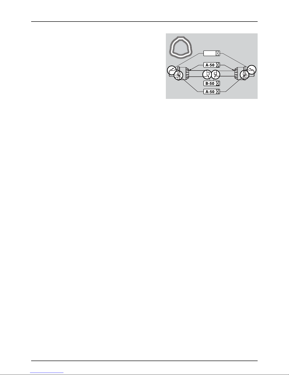
6 - Maintenance
78
PTO Lubrication & Oiling Plan
PTO shaft, type 100 series
C-50

6 - Maintenance
79
Service and Maintenance Intervals
Boom and Centre
After first use
μ
ATTENTION! Please refer to Boom Manual for Boom and Centre service and intervals.
10 Hours Service - EasyClean Filter
This filter has a clogging indicator as mentioned in the “Description”
chapter, but even if this indicator does not show clogging, the filter
mostly needs cleaning every 10 hours.
Servicing the filter
1. Turn the filter lid counterclockwise to open it.
2. Remove lid and filter from the filter housing.
3. Separate filter element from lid/filter guide by turning locks
outwards.
4. Clean filter and if necessary clean the housing for larger impurities.
To reassem b l e
1. Grease the O-ring on the filter lid.
2. Press the filter onto the filter guide/lid. Make sure that it has caught
the guide.
3. Reassemble filter/filter lid into the housing. Make sure that it has
caught the guide in the bottom of the housing.
4. Turn the filter lid clockwise to close it.
±
WAR NING! Al ways we ar protective clothing and gloves before
servicing the filter!
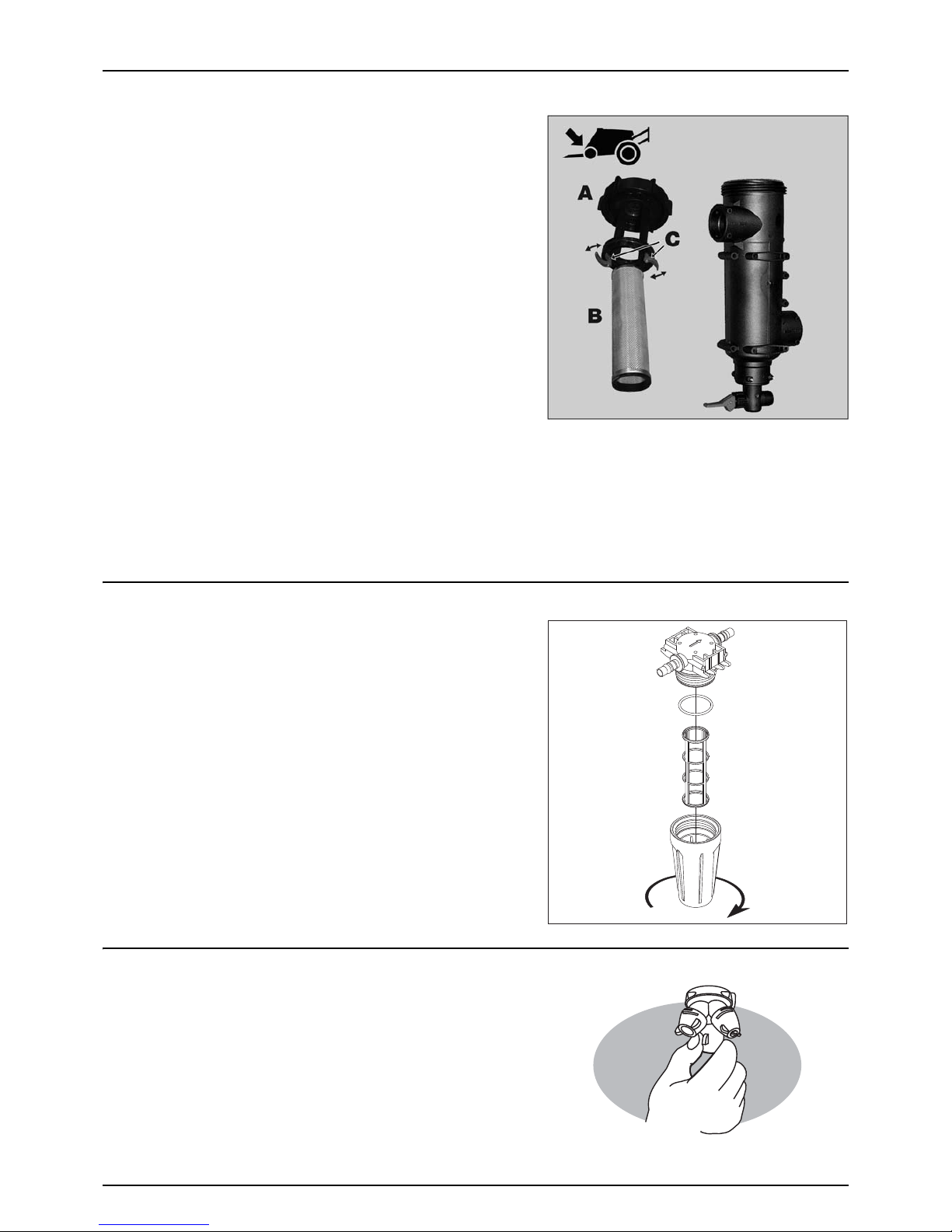
6 - Maintenance
80
10 Hours Service - CycloneFilter
Servicing the filter
1. Turn the pressure valve towards the unused function or to tank
cleaning nozzles.
2. Unscrew the filter lid (A).
3. Lift lid and filter (B) from the housing.
4. Turn the two locks (C) outwards to unlock the filter from the lid.
5. Separate filter from the integrated filter guide in the lid and clean
the filter.
To reassem b l e
1. Grease the two O-rings on the lid/filter guide. Due to small space
at lid, use for example a brush to apply the grease.
2. Mount the filter onto the recess (which may not be greased) in the
lid/filter guide.
3. Turn the two locks (C) inwards to lock the filter to the lid.
4. Place the filter/filter lid into the housing and screw the lid, until it hits the stop.
±
WARNING! Always wear protective clothing and gloves, before servicing the filter!
€
DANGER! The pressure valve must always be turned to the unused function or to tank cleaning nozzles, before
opening the CycloneFilter! If not, the spraying liquid can hit you, when opening the filter, and the main tank content
will drain away!
10 Hours Service - In-Line Filter (optional)
If the boom is equipped with In-Line Filters, unscrew the filter bowl to
inspect and clean the filter. When reassembling, the O-ring should be
greased.
Alternative filter meshes are available. See section on Technical
specifications - Filters and nozzles.
±
WARNING! Be careful not to splash out liquid, when unscrewing
the filter bowl.
±
WARNING! Always wear protective clothing and gloves, before
servicing the filter!
10 Hours Service - Nozzle Filters
The filters are located inside the nozzles. Check and clean.

6 - Maintenance
81
10 Hours Service - Spraying Circuit
Fill with clean water and operate all functions. Check for leaks using a higher spray pressure than normal. Check nozzle spray
patterns visually using clean water.
10 Hours Service - Brakes (optional)
Apply brake pedal and check function of trailer brakes.
50 Hours Service - Transmission Shaft
Check function and condition of the transmission shaft protection guard. Replace any damaged parts.
50 Hours Service - Wheel Nuts
Tighten wheel nuts as follows.
Torque wrench setting for mounting wheel hub to rim plate: 490 Nm.
Tightening sequence for wheel nuts: See illustration and tighten in the
numbered order.
μ
ATTENTION! When wheels has been mounted or re-tightened,
the plastic nut covers must be placed on the nuts afterwards.
50 Hours Service - Tyre Pressure
Check the tyre pressure according to the table in “Technical Specifications”.
€
DANGER! Never inflate tyres more than to the pressure specified in the table. Over-inflated tyres can explode and
cause severe injuries! See the section “Occasional Maintenance - Change of Tyres”.
±
WARNING! If renewing tyres, always use tyres with minimum load index as specified.
250 Hours Service - Readjustment of the Boom
Please refer to Boom Manual
250 Hours Service - Hydraulic Circuit
Check the hydraulic circuit for leaks and repair, if needed.
Refill nitrogen accumulators for:
• ParaLift
• Suspension (if fitted)
±
WARNING! Hoses for boom lifting device must be changed after every 5 years of use.
±
WARNING! Nitrogen accumulators may contain oil under pressure.
250 Hours Service - Hoses and Tubes
Check all hoses and tubes for possible damage and proper attachment. Replace damaged hoses or tubes.
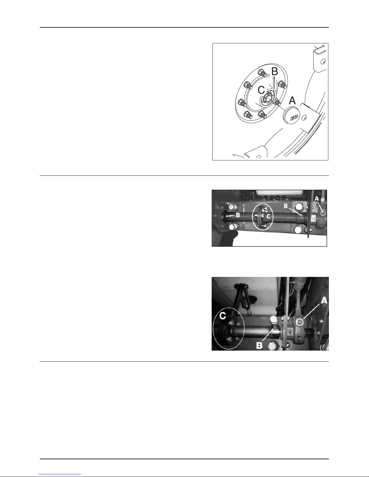
6 - Maintenance
82
250 Hours Service - Wheel Bearings
Check for play in the wheel bearings:
1. Place stop wedges in front of and behind the left wheel and jack
up right wheel.
2. Rock the right wheel to discover possible play in the bearings.
3. If any play, support the wheel axle to prevent the trailer from falling
down from the jack.
4. Remove hub cap (A) and cotter pin (B). Turn the wheel and tighten
the castle nut (C), until a slight resistance is felt in the wheel
rotation.
5. Loosen the castellated nut until the first notch - horizontal or
vertical - is aligned with the cotter pin hole in the shaft.
6. Fit a new cotter pin and bend it to keep it in place.
7. Fit the hub cap to the hub again.
8. Repeat the procedure for the left wheel.
250 Hours Service - Brake Adjustment (optional)
Lift the back of the sprayer from the ground. It is recommended to use
two lifting jacks, which are placed under the wheel axle. Make sure the
sprayer is stable and secured before carrying out any adjustments.
μ
ATTENTION! There are two versions of the hand brake system
available, one of the pictures should show your system at hand.
1. Loosen the 4 bolts at the brake connector (C) between the brake
arms. Also loosen the screw in each end of the brake connector
and the hand brake cable.
2. Adjust the nut (A) counterclockwise. Turn the nut 60° (1/6 turn) at a time - alternately on both left and right brake.
Continue the adjustment, until resistance occurs when rotating the hub/wheel.
3. Turn the nut 60° (1/6 turn) clockwise to loosen brake. Hub/wheel
should rotate freely now.
4. Tighten the brake connector (C) bolts again.
5. Tighten the hand brake cable again - See “250 Hours Service -
Brake Adjustment (optional)” on page 82.
±
WARNING! The adjustment must be carried out simultaneously
on both brakes. Therefore, adjust both left brake and right brake
alternately.
250 Hours Service - Hydraulic Brakes (optional)
Apply brakes to full pressure and inspect brake lines for damages or leaks. Replace damaged parts. If the hydraulic brake lines
have been dismantled, the hydraulic circuit must be vented afterwards:
1. Loosen the brake hose at both brake cylinders.
2. Apply the brake, until oil without air bubbles comes out.
3. Tighten the brake hose, before relieving the brake again.
±
WARNING! Always vent the circuit, if the hydraulic brake lines have been dismantled.
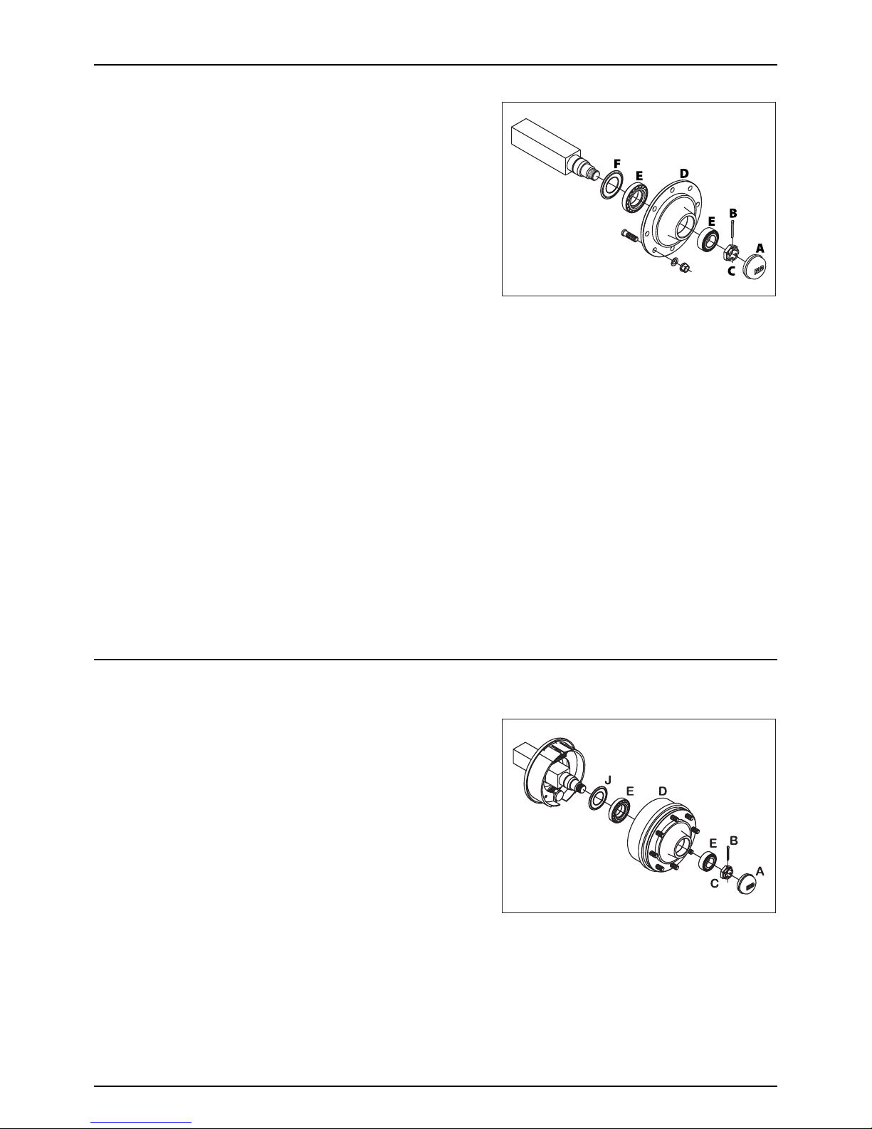
6 - Maintenance
83
1000 Hours Service - Wheel Bearings (No Brakes)
Check the condition of the bearings in the following way:
1. Place stop wedges in front of and behind the left wheel and jack
up the right wheel.
2. Support the trailer with axle stands.
3. Remove the wheel.
4. Unscrew the 6 bolts and remove the hub cap (A), cotter pin (B) and
castle nut (C).
5. Pull off the wheel hub (D). Use a wheel puller if necessary.
6. Remove roller bearings (E). Clean all parts with a degreasing
detergent and wipe them.
7. Check roller bearings (E) for discolouration and wear. Replace if worn or damaged.
8. Assemble the hub (D) and bearings (E) using a new sealing ring (F).
9. Fill the hub (D) and bearings (E) with new grease, before fitting them to the wheel axle.
10. Fit the castle nut (C). Rotate the hub (D) and tighten the castle nut (C), until a slight resistance in the rotation is felt.
11. Loosen the castle nut (C) again, until the first notch is aligned with the cotter pin hole in the axle.
12. Fit a new cotter pin (B) and bend it to keep it in place.
13. Fit the hub cap (A) to the hub (D). Slightly tighten the 6 bolts.
14. Fit the wheel again and tighten the wheel nuts. See section “50 hours service” regarding torque wrench setting.
Tighten all bolts to half the specified torque at first, then tighten to the full specified torque.
15. Tighten again after 10 hours of work. Check the torque every day, until it is stabilised.
μ
ATTENTION! The wheel axle has a vertical and an horizontal cotter pin hole. Use the one first aligned with the notch,
when loosening the castle nut.
±
WARNING! If you do not feel totally confident changing wheel bearings, then contact your HARDI dealers workshop.
1000 Hours Service - Wheel Bearings and Brakes
Check the condition of the bearings and brake wear parts in the following way:
1. Place stop wedges in front of and behind the wheel opposite to
the one to be serviced (e.g.left wheel). Jack up the wheel to be
serviced (e.g. right wheel).
2. Support the trailer with axle stands.
3. Remove the wheel.
4. Unscrew the 6 bolts and remove the hub cap (A), cotter pin (B) and
castle nut (C).
5. Pull off the brake drum (D). Use a wheel puller if necessary.
6. Vacuum the brake drum (D) for brake dust, or rinse it with water.
€
DANGER! Brake dust can cause severe health injuries! Avoid inhalation of brake dust! Wear a respirator when servicing
the brakes. Do not clean brakes with compressed air! Use a vacuum cleaner or rinse with water to avoid brake dust
being blown around.
7. Rinse the remaining parts on the brake carrier plate with water and wipe them.
8. Remove roller bearings (E), clean all parts with a degrease detergent and wipe them.
9. Check the brake drum diameter and lining thickness. Replace if worn.
Max. wear rates on brake components:
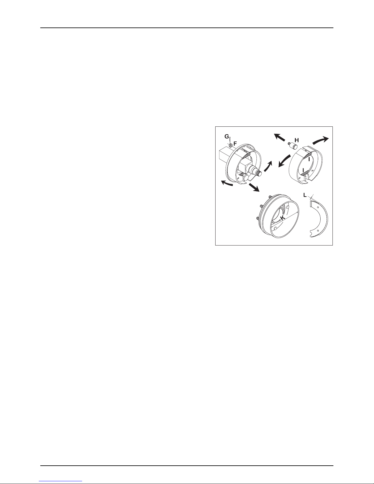
6 - Maintenance
84
• Max. drum diameter: 302 mm (Small drums)
• Max. drum diameter: 402 mm (Large drums)
• Min. lining thickness: 2.0 mm
±
WARNING! The specified minimum thickness is the absolute minimum, which must never be exceeded. Replace the
parts, if they would reach the above dimensions before the next service inspection.
±
WARNING! Renewal of brake linings or brake drums must be done for both sides at the same time.
μ
ATTENTION! If the brake drum must be removed from the wheel hub, a hydraulic press is required to press the wheel
studs out.
10. Remove the clevis pin between the air diaphragm cylinder and the
brake cam lever.
11. Remove the cotter pin (G), castle nut (F) and the brake shoe anchor
bolt (H), and slide the brake shoes over the cam. Twist the pair of
brake shoes to remove the shoe return springs (I). Replace the
brake shoes, if the linings are worn.
12. Apply a small amount of copper paste on moving parts and
reassemble the brake shoes and shoe return springs (I).
±
WARNING! Do not get copper paste in contact with the brake
linings and drums.
13. Fit the shoe assembly with the anchor bolt (H) first. Then pull the
shoes away from each other and slide them over the cam
afterwards. Tighten the anchor bolt castle nut (F) again, and fit a
new cotter pin (G).
14. Check roller bearings for discolouration and wear. Replace if worn
or damaged.
15. Assemble drum (D) and bearings (E) using a new sealing ring (J ).
16. Fill the hub and bearings with new grease, before fitting them to the wheel axle.
±
WARNING! Do not get oil or grease in contact with the brake linings and drums.
17. Fit the castle nut (C). Rotate the brake drum (D) and tighten the castle nut (C), until a slight rotation resistance is felt.
18. Loosen the castle nut (C) again, until the first notch is aligned with the cotter pin hole in the axle.
μ
ATTENTION! The shaft has a vertical and an horizontal cotter pin hole. Use the one first aligned with the notch when
loosening the castle nut.
19. Fit a new cotter pin (B) and bend it to keep it in place.
20. Fit the hub cap (A) to the hub. Slightly tighten the 6 bolts.
21. Fit the wheel again and tighten the wheel nuts. See “50 Hours Service - Wheel Nuts” on page 81 regarding torque
wrench setting. Tighten all bolts to half the specified torque at first, then tighten to the full specified torque.
22. Tighten again after 10 hours of work. Check the torque every day, until it is stabilised.
±
If you do not feel totally confident changing wheel bearings or brakes, then contact your HARDI dealers workshop.
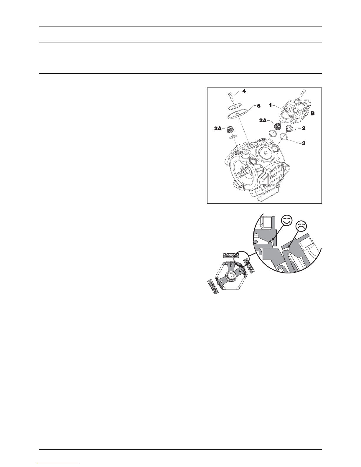
6 - Maintenance
85
Occasional Maintenance
General Info
The maintenance and service intervals for the following components will depend very much on the conditions, under
which the sprayer is operated, and therefore it is almost impossible to specify the intervals.
Pump Valves and Diaphragms Renewal
Pump model: 363 and 463.Diaphragm pump overhaul kit (valves, seals,
diaphragms etc.) can be ordered. Detect the pump model - the overhaul
kit can be ordered by your local dealer.
Model 363: Item no. 75073700
Model 463: Item no. 75073900
Val ves
Remove valve cover (1) before changing the valves (2) - note their
orientation, so that they are replaced correctly!
μ
ATTENTION! A special valve with white flap (2A) is used at the two
upper side inlets. It has to be placed in the valve openings as
shown. All others are the type with black flap. It is recommended
to use new gaskets (3), when changing or checking the valves.
Diaphragms
Remove the diaphragm cover (4). The diaphragm (5) may then be
changed. If fluids have reached the crankcase, re-grease the pump
thoroughly. Also check that the drain hole at the bottom of the pump is
not blocked.
Reassemble the pump with the following torque setting.
Diaphragm cover: 90 Nm.
Diaphragm bolt: 90 Nm.
μ
ATTENTION! Before tightening the 4 bolts for the diaphragm cover (B), the diaphragm must be positioned between
centre and top to ensure correct sealing between diaphragm pump housing and diaphragm cover. Turn the crank
shaft if necessary.
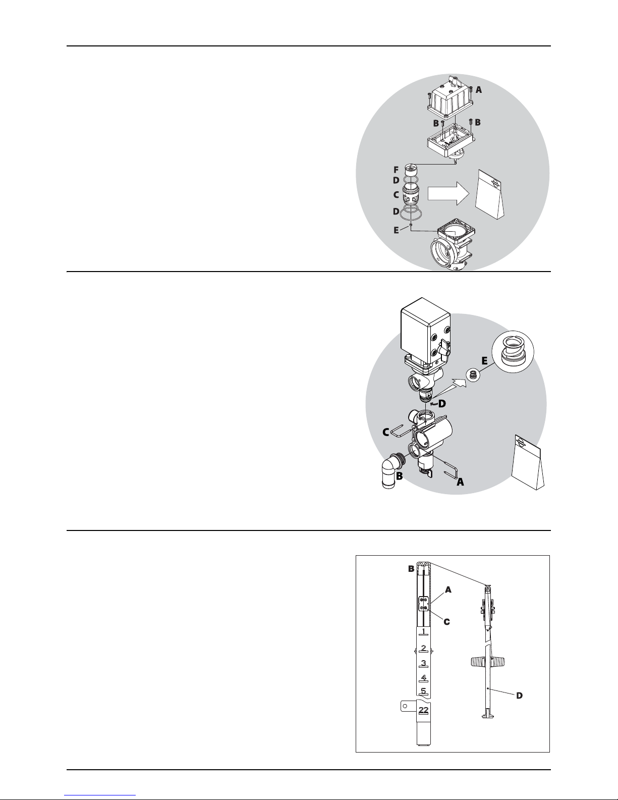
6 - Maintenance
86
Cone check/renewal for pressure regulation valve
If it becomes difficult to build up sufficient pressure or if pressure
fluctuations occur, it may be necessary to renew cone and cylinder.
1. Remove 4 x screws (A) and remove the housing.
2. Remove 4 x screws (B).
3. Replace cylinder (C) and O-ring (D).
4. Loosen the nut (E), remove and replace the cone (F).
5. Reassemble in reverse order.
Cone check/renewal for EVC distribution valve
Periodically check the distribution valves for proper sealing. Do this by
running the sprayer with clean water and open all distribution valves.
Cautiously remove the clip (A) and pull out the hose (B) for the return
line. When the housing is drained, there should be no liquid flow
through the return line.
If there is any leakage, the valve cone (E) must be changed.
1. Remove the clip (C)
2. Lift the motor housing off the valve housing.
3. Unscrew the screw (D) and replace the valve cone (E).
4. Reassemble in reverse order.
Level Indicator Adjustment
The level indicator reading should be checked regularly. When the tank
is empty, the float should lie on the stop pin (D) of the rod, and the Oring on the indicator should be positioned at the top position line (A).
If any deviation is found, do the following:
1. Pull out the plug (B).
2. Loosen screws (C).
3. Adjust the length of the cord, until it reads correctly.
4. Push the plug (B) back into place.
÷
NOTE! To obtain the best accuracy, the adjustment shall be done
with the sprayer attached to the tractor normally used.

6 - Maintenance
87
Level Indicator Cord Renewal
If the cord on the level indicator has to be changed, the float guide pole is removed:
1. Remove the tank drain valve (see the following section “Drain Valve Seal Replacement”) and loosen the fitting holding
the pole in position.
2. Pull the pole down through the drain valve hole, until it is free in the top of the tank.
3. The pole can now be taken out of the tank through the filling hole.
€
DANGER! Do not enter the inside of the tank - the parts can be changed from the outside of the tank!
Drain Valve Seal Replacement
If the main tank drain valve leaks, the seal and seat can be changed in
the following way.
€
DANGER! Do not enter the inside of the tank - the parts can be
changed from the outside of the tank!
±
WARNING! Use eye / face protection mask, when dismantling the
tank drain valve!
1. Make sure that the tank is empty and clean.
2. The valve must be closed and the string must be loose.
3. Pull out the clip (A) and pull down the connecting piece (B). The
entire valve assembly can now be pulled out.
4. Check cord and valve flap assembly (C) for wear, replace seal (D)
and reassemble.
5. Reassemble the valve using a new valve seat (E). Lubricate O-rings (F) before assembly.
6. Fit clip (A) again.
μ
ATTENTION! Check the valve function using clean water, before filling chemicals into the tank.
Nozzle Tubes and Fittings
Poor sealings are usually caused by:
• Missing O-rings or gaskets
• Damaged or incorrectly seated O-rings
• Dry or deformed O-rings or gaskets
• Foreign objects
In case of leaks:
DO NOT overtighten. Disassemble, check condition and position of Oring or gasket. Clean, lubricate and reassemble.
The O-ring must be lubricated ALL THE WAY ROUND, before fitting it on
to the nozzle tube. Use non-mineral lubricant.
For AXIAL connections, a little mechanical leverage may be used.
For RADIAL connections, only tighten by hand.

6 - Maintenance
88
Adjustment of 3-Way Valve
The large ball valve (type s93) can be adjusted, if it is too tight to
operate - or if it is too loose (=liquid leakage).
• Correct setting is when the valve can be operated smoothly by one
hand.
Use a suitable tool and adjust the toothed ring inside the valve as shown
on the drawing.
μ
ATTENTION! The small ball valves (type s67) cannot be adjusted.
Retighten the Frame
The frame are two sections bolted together. Also the drawbar is bolted to the frame. These bolts need to be tightened
correctly. Check regularly if bolts are tightened according to the specified torques below.
Change of Bulbs
1. Switch off the light.
2. Loosen the screws on the lamp and remove the cover or lens.
3. Remove the bulb.
4. Fit a new bulb, refit the cover and tighten the screws.
μ
ATTENTION! If halogen bulbs are used, never touch the bulb with your fingers. Natural moisture in the skin will cause
the bulb to burn out, when the light is switched on. Always use a clean cloth or tissue when handling halogen bulbs.
Wear Bushing Renewal on Steering
If too much play is found in the steering, the wear bushes must be replaced. This should be done at your local HARDI dealer.
180 Nm
250 Nm
250 Nm
250 Nm
180 Nm
180 Nm

6 - Maintenance
89
Suspension Rubber Dampers (optional)
If the shock absorbers loose their efficiency, they should be replaced.
1. Connect the sprayer to a tractor to prevent overbalancing.
2. Lift the rear end of the sprayer with e.g. a crane. Use lifting points as described in “Sprayer setup”.
3. Loosen the nut below the suspension rubber dampers.
4. Remove the suspension rubber dampers and replace with new ones.
5. Tighten the nut below the suspension rubber dampers.
6. Lower the rear of the sprayer again.
Shield Replacement on Transmission Shaft
• See the manufacturer’s instruction book.
Replacement of Transmission Shaft Cross Journals
• See the manufacturer’s instruction book.
Change of Tyres
€
DANGER! If it is time to change tyres, it is recommended to leave this job to a specialist and follow the rules below.
Some mounting instructions are usually printed on the tyre itself.
• Always clean and inspect the rim before mounting a new tyre.
• Always check that the rim diameter corresponds exactly to the rim diameter moulded on the tyre.
• Always inspect the tyre inside for cuts, penetrating objects or other damages. Repairable damages should be repaired
before installing the tube. Tyres with non-repairable damages must never be used.
• Also inspect the tyre inside for dirt or foreign objects. Remove this before installing the tube.
• Always use tubes of recommended size and in good condition. When fitting new tyres, always fit new tubes.
• Before mounting, always lubricate both tyre beads and rim flange with approved lubricating agent or equivalent
anticorrosion lubricant. Never use petroleum based greases and oils, because they may damage the tyre. Using the
appropriate lubricant will prevent the tyre from slipping on the rim.
• Always use specialised tools for mounting the tyres as recommended by the tyre supplier.
• Make sure that the tyre is centred, and that the beads are perfectly seated on the rim. Otherwise tearing of the bead
wire may occur.
• Inflate the tyre to 1-1.3 bar (14.5-19 psi), then check whether both beads are seated perfectly on the rim. If any of the
beads do not seat correctly, deflate the assembly and re-centre the beads, before starting inflation of the tyre. If the
beads are seated correctly on the rim at 1-1.3 bar (14.5-19 psi), inflate the tyre to a maximum of 2.5 bar (36 psi), until
they seat perfectly on the rim.
• Never exceed the maximum mounting pressure moulded on the tyre!
• After mounting tyres adjust inflation pressure to operation pressure recommended by the tyre manufacturer.
• Do not use tubes in tubeless tyres.
€
DANGER! No observance of mounting instructions will result in a bad seating of the tyre on the rim, and it could cause
the tyre to burst leading to serious injury or death! DANGER! Never mount or use damaged tyres or rims! Use of a
damaged, ruptured, distorted, welded or brazed rim is not allowed!

6 - Maintenance
90
Safety Valve Activation
To make the fluid system work perfectly over time, it is good practice to regularly provoke opening of the safety valve.
This avoids clogging and ensures proper function of the safety valve. Opening of the valve is done by turning the pressure
SmartValve to “Pressure draining” or an unused function, when the pump is running. This is good practice for all sprayers,
but particularly for sprayers without optional equipment.
€
DANGER! Before turning pressure SmartValve to “Pressure draining”, it is very important to be sure that the quick
coupler lid is correctly and completely mounted to the filling stud in its locked position. Failure to do so causes a risk
of contamination and injury from the quick coupler lid being “shot” off when pressurized! If it is not possible to mount
lid completely, lubricate the rubber seal and the grip hooks.

6 - Maintenance
91
Off-Season Storage
Off-Season Storage Program
To preserve the sprayer intact and to protect its components, the following off-season storage program is carried out.
Before storage
When the spraying season is over, you should devote some extra time to the sprayer. If chemical residues are left over in the
sprayer for longer periods, it may reduce the life of its individual components.
1. Clean the sprayer completely - inside and outside - as described under “Cleaning” on page 71. Make sure that all valves,
hoses and auxiliary equipment have been cleaned with detergent and flushed with clean water afterwards, so that no
chemical residues are left in the sprayer.
2. Replace any damaged seals and repair any leaks.
3. Empty the sprayer completely, and let the pump work for a few minutes. Operate all valves and handles to drain as
much water off the spraying circuit as possible. Let the pump run until air comes out of all nozzles. The rinsing tank is
also drained.
4. Pour approximately 50 litres of antifreeze mixture, consisting of 1/3 anti-freeze and 2/3 water, into the tank.
5. Engage the pump and operate all valves and functions, operating unit, chemical inductor etc., allowing the antifreeze
mixture to be distributed around the entire circuit. Open the operating unit main valve ON/OFF and distribution valves,
so that the antifreeze is sprayed through the nozzles as well. The antifreeze will also prevent O-rings, seals, diaphragms
etc. from drying out. On sprayers with a FlexCapacity pump, this must also be engaged and flushed.
6. Lubricate all lubricating points according to the lubricating intervals.
7. When the sprayer is dry, remove rust from scratches or damage in the paint, if any, and touch up the paint.
8. Remove the glycerine-filled pressure gauges and store them frost-free in vertical position.
9. Apply a thin layer of anti-corrosion oil (e.g. SHELL ENSIS FLUID, CASTROL RUSTILO or similar) on all metal parts. Avoid
oil on rubber parts, hoses and tyres.
10. Fold the boom in transport position and relieve pressure from all hydraulic functions.
11. All electric plugs and sockets are to be stored in a dry plastic bag to protect them against moisture, dirt and corrosion.
12. Remove the control boxes and computer display from the tractor. Store them dry and clean (indoor) in a non-
condensing environment.
13. Wipe hydraulic snap-couplers clean and fit the dust caps.
14. Apply grease to all hydraulic ram piston rods, which are not fully retracted in the housing, to protect against corrosion.
15. Chock the wheels, to prevent moisture damage and deformation of the tyres. Tyre blacking can be applied to the tyre
walls to preserve the rubber.
16. Drain air brake tank for condensed water.
17. To protect against dust, the sprayer can be covered by a tarpaulin. Ensure ventilation to prevent condensation.

6 - Maintenance
92
After storage
After a storage period, the sprayer should be prepared for the next season the following way:
1. Remove the tarpaulin.
2. Remove the support for the wheel axle, and adjust the tyre pressure.
3. Wipe off the grease from hydraulic ram piston rods.
4. Fit the pressure gauges again. Seal with Teflon tape.
5. Connect the sprayer to the tractor, including hydraulics and electrics.
6. Check all hydraulic and electric functions.
7. Empty the tank for remaining antifreeze.
8. Rinse the entire liquid circuit of the sprayer with clean water.
9. Fill with clean water and check all functions.
10. Check function of the brakes. Please note that brake power will be reduced, until the rust is worn off the drums. Always
brake lightly until the drums are clean.

6 - Maintenance
93

6 - Maintenance
94

95
7 - Fault finding
Operational Problems
General Info
Operational incidents are often due to the same reasons:
1. A suction leakage reduces the pump pressure and may interrupt suction completely.
2. A clogged suction filter may damage suction or interrupt and prevent the pump from running normally.
3. A clogged pressure filter increases pressure in the fluid system in front of the pressure filter. This may blow the safety
valve.
4. Clogged in-line filters or nozzle filters increase pressure in the pressure gauge, but it decreases pressure at the nozzles.
5. Impurities sucked in by the pump may prevent the valves from closing correctly, thus reducing the pump flow.
6. A bad reassembly of the pump elements, especially the diaphragm covers, causes air intakes or leaks and reduces the
pump flow.
7. Rusted or dirty hydraulic components cause bad connections and early wears.
8. A poorly charged or faulty battery causes failure and misbehaviour in the electrical system.
Therefore ALWAYS check that
1. Suction and pressure filters, as well as nozzles, are clean.
2. Hoses are free of leaks and cracks, especially suction hoses.
3. Gaskets and O-rings are present and in good condition.
4. Pressure gauges are in good working order. Dosage accuracy depends on it.
5. Operating unit functions properly. Use clean water to check.
6. Hydraulic components are clean.
7. The tractor battery and its connectors are in good condition.

7 - Fault finding
96
Liquid System
FAULT PROBABLE CAUSE CONTROL/REMEDY
No spray from boom when turned on. SmartValve positions are wrong. Set correct valve positions for spraying.
Suction/pressure filters are clogged. Clean suction and pressure filters.
No suction from tank. See if suction fitting in main tank sump is free of
sedimentation. Clean if needed.
Lack of pressure. Incorrect assembly. Boost valve is open.
Air in system. Fill suction hose with water for initial priming.
Too much agitation. Close the agitation valve.
Pump valves are blocked or worn. Check for obstructions and wear.
Blocked filters Clean all filters.
Defective pressure gauge. Check for dirt at inlet of pressure gauge.
Pressure dropping. Filters are clogging. Clean all filters. Fill with cleaner water. If using
powders, make sure agitation is on.
Nozzles are worn. Check flow rate. Replace nozzles, if it exceeds 10%.
Sucking air towards end of tank load. Lower pump speed (rpm).
Pressure increasing. Pressure filters beginning to clog. Clean all filters.
Formation of foam. Air is being sucked into system. Check tightness/gaskets/O-rings of all fittings on
suction side.
Excessive liquid agitation. Lower pump speed (rpm).
Check safety valve is tight.
Ensure returns inside the tank are present.
Use a foam damping additive.
Liquid leaks from bottom of the pump. Damaged diaphragm. Replace diaphragm. See relevant section.
Vibrations in system and unpleasant noise from the
pump.
Air is being sucked into system. Check for leaks, holes in hoses, tightness/gaskets/O-
rings of all fittings on the suction side.
Operating unit is not functioning, or it is having a
malfunction.
Blown fuse(s). Check mechanical function of micro switches. Use
cleaning/lubricating agent if the switch does not
operate freely.
Check motor current, max. 450-500 mA. If over,
change the motor.
Wrong polarity. Brown to positive (+). Blue to negative (-).
Valves not closing properly. Check valve seals for obstructions.
Check micro switch plate position. Loosen the screws
holding the plate a 1/2 turn.
No power. Wrong polarity. Check that brown is positive (+), blue
is negative (-).
Check print plate for dry solders or loose connections.
Check fuse holder is tight around fuse.

7 - Fault finding
97
Hydraulic System, Y-boom version
Hydraulic System, Z-boom version
FAULT PROBABLE CAUSE CONTROL/REMEDY
Boom slow/eradic. Air in system. Loosen ram connection and activate hydraulics until
oil flow has no air in it (not whitish).
Regulation valve incorrectly set. Open or close until desired speed is achieved
(clockwise = less speed).
Remember oil must be at operating temperature.
Insufficient hydraulic pressure. Check output pressure of tractor hydraulics. Minimum
for sprayer is 170 bar.
Insufficient amount of oil in tractor reservoir. Check and top if needed.
Ram not functioning. Restrictor or regulation valve blocked. Secure boom. Dismantle and clean.
Hydraulic system fold/tilt functions will not operate. Power supply. Check for proper 12V power supply.
One function (fold or tilt) will not operate. Various. Check for defective switch(s).
Check continuity of cables.
Check for operation of applicable solenoid (coil not
activating or plunger stuck).
Check for short circuit in wiring junction box at rear of
sprayer.
Dirt in the restrictor port of the cylinder.
Multiple hydraulic functions with one switch
activated.
Various. Check for correct solenoid electric/hydraulic hook-up.
Check for short circuit in wiring in the junction box at
rear of sprayer.
FAULT PROBABLE CAUSE CONTROL/REMEDY
No boom movements when activated. Insufficient hydraulic pressure. Check oil pressure.
Check tractor hydraulic oil level.
Insufficient oil supply. Oil flow must be min. l/min. and max. 130 l/min.
Check tractor hydraulic oil level.
Blown fuse(s). Check / replace fuse in junction box.
Bad / corroded electrical connections. Check / clean connections, multi plugs etc.
Insufficient power supply. Voltage on activated solenoid valve must be more
than 8 volts.
Use wires of at least 4 mm for power supply.
Defective relay / diodes in junction box. Check relays, diodes and soldering at PCB in junction
box. LED diodes indicate boom functions.
Clogged restrictors in bypass block. Remove and clean restrictors in bypass block (See
hydraulic diagram). Change hydraulic oil + filter.
Wrong polarity. Check polarity. Red positive (+), black negative (-).
ParaLift lock does not lock.
Boom lift raises to max. position, when tractor
hydraulics are engaged.
Back pressure in return line exceeds 15 bar. Connect the return line with a free flow to hydraulic oil
reservoir.
Divide return line in two and lead return oil back to
reservoir via two spool valves.
Oil heats up in Closed Centre systems. Bypass valve does not close properly. Check / close (screw in) by-pass valve.
Internal leaks in flow regulator. Replace flow regulator O-rings and backup rings.
Replace flow regulator.
Individual hydraulic piston does not move. Clogged restrictor. Dismantle and clean restrictor.

7 - Fault finding
98
IntelliTrack
FAULT PROBABLE CAUSE CONTROL/REMEDY
IntelliTrack steers slowly or erratically. Air in system. Vent the Intellitrack cylinders - see “Venting the Steering
Hydraulics”
Front potentiometer bar/springs move
erratically.
Re-arrange the spring setup, so that the potentiometer bar
moves freely.
IntelliTrack has non-linear steering or is not
following the tractor’s track.
Front potentiometer springs are not parallel. Refit springs to parallel position and check potentiometer
reading - see “IntelliTrack Front Potentiometer Calibration”.
 Loading...