

Page 1
NAVIGATOR
550M, 800M, 1000M Centrifugal
Operator's Manual
10613903 (8/04)
Page 2

Page 3

NAVIGATOR
550M, 800M, 1000M Centrifugal
Operator's Manual
10613903 (8/04)
HARDI® reserves the right to make changes in design,
material, or specifi cation without notice thereof.
HARDI® and other product names are registered trademarks
of HARDI® Inc. in the U.S. and in other countries.
Page 4

TABLE OF CONTENTS
1.0 INTRODUCTION . . . . . . . . . . . . . . . . . . . . . . . . . . . . . . . . . 6
2.0 SAFETY INFORMATION . . . . . . . . . . . . . . . . . . . . . . . . . . 7
2.1 Follow Safety Instructions . . . . . . . . . . . . . . . . . . . 8
2.2 Operating the Sprayer Safely . . . . . . . . . . . . . . . . . 8
2.3 Handling Chemical Products Safely . . . . . . . . . . . . 10
2.4 Local Poison Information Center . . . . . . . . . . . . . . 11
3.0 HOOKING UP THE SPRAYER . . . . . . . . . . . . . . . . . . . . . . 12
3.1 Clevis Hitch . . . . . . . . . . . . . . . . . . . . . . . . . . . . . . 12
3.2 Wheel Spacing and Ground Clearance . . . . . . . . . 12
3.3 Hydraulic Driven Centrifugal Pump . . . . . . . . . . . . 14
3.4 P.T.O. Shaft Operator Safety (P.T.O. Driven Pumps Only) 15
3.5 Installation Of P.T.O. Shaft (P.T.O. Driven Pumps Only) .16
3.6 Hydraulic Requirements . . . . . . . . . . . . . . . . . . . . . 17
3.7 Control Box For ESC Control Unit . . . . . . . . . . . . . 18
4.0 OPERATING INSTRUCTIONS . . . . . . . . . . . . . . . . . . . . . . 19
4.1 Operating the Boom . . . . . . . . . . . . . . . . . . . . . . . . 19
4.2 Filling The Main Tank . . . . . . . . . . . . . . . . . . . . . . . 19
4.3 Filling The Flush Tanks (If fi tted) . . . . . . . . . . . . . . . 19
4.4 Manifold Sprayer Plumbing Diagram . . . . . . . . . . . 20
4.5 Manifold System . . . . . . . . . . . . . . . . . . . . . . . . . . . 20
4.6 Manifold Operating Instructions . . . . . . . . . . . . . . . 22
4.7 Operation of Centrifugal Bypass Kit (Early models only) 23
4.8 Adjustment Of the ESC Controls . . . . . . . . . . . . . . 24
4.9 Adjustment of Constant Pressure . . . . . . . . . . . . . 25
4.10 Agitation Adjustment (Agitation Nozzles Only) . . . . 26
4.11 Adding Chemicals . . . . . . . . . . . . . . . . . . . . . . . . . 27
4.12 Use of Flush Tank and Rinse Nozzles (optional) . . 32
4.13 Operation Of The Tank Drain Valve . . . . . . . . . . . . 34
4.14 Nozzle Selection . . . . . . . . . . . . . . . . . . . . . . . . . . 35
4.15 Calibration . . . . . . . . . . . . . . . . . . . . . . . . . . . . . . . 38
5.0 MAINTENANCE . . . . . . . . . . . . . . . . . . . . . . . . . . . . . . . . . 42
5.1 Cleaning The Sprayer . . . . . . . . . . . . . . . . . . . . . . . 42
5.2 Filters . . . . . . . . . . . . . . . . . . . . . . . . . . . . . . . . . . . 44
5.3 Recommended Tire Pressure . . . . . . . . . . . . . . . . 45
5.4 Wheel Nuts and Bearings Adjustment . . . . . . . . . . 45
2 HARDI® NAVIGATOR 550M, 800M, 1000M CENTRIFUGAL OPERATOR'S MANUAL
Page 5

5.5 Tandem Axles . . . . . . . . . . . . . . . . . . . . . . . . . . . . . 46
5.6 Nozzle Tubes And Fittings . . . . . . . . . . . . . . . . . . . 47
5.7 Checking the Valve Cone in Distribution Valves . . . 48
5.8 Hydraulic Driven Pump Repair Parts . . . . . . . . . . . 48
5.9 P.T.O. Belt Driven Pump Repair Parts . . . . . . . . . . 49
5.10 Emergency Operation Of ESC Controls . . . . . . . . . 50
5.11 Level Indicator . . . . . . . . . . . . . . . . . . . . . . . . . . . . 50
5.12 Lubrication . . . . . . . . . . . . . . . . . . . . . . . . . . . . . . . 51
6.0 OFF-SEASON STORAGE . . . . . . . . . . . . . . . . . . . . . . . . . 54
6.1 Preparation After Off-Season Storage . . . . . . . . . . 55
7.0 ACCESSORIES . . . . . . . . . . . . . . . . . . . . . . . . . . . . . . . . . 56
7.1 Clean Water Dispenser . . . . . . . . . . . . . . . . . . . . . 56
7.2 Chemical Filler (optional) . . . . . . . . . . . . . . . . . . . . 56
7.3 Chemical Filler Bag & Bottle Rinse Kit (optional) . . 57
7.4 Nurse Tank Quick Fill (optional) . . . . . . . . . . . . . . . 57
7.5 Foam Marker System (optional) . . . . . . . . . . . . . . . 58
7.6 4" Boom Pressure Gauge (optional) . . . . . . . . . . . 59
7.7 Flush System (optional) . . . . . . . . . . . . . . . . . . . . . 59
7.8 Tank Rinse System (optional) . . . . . . . . . . . . . . . . 60
7.9 Spraygun And Hose wrap (optional) . . . . . . . . . . . 61
7.10 HARDI® Monitor 1500 (optional) . . . . . . . . . . . . . . 61
7.11 HARDI® Controller 2500 (optional) . . . . . . . . . . . . . 62
7.12 Mustang 3500 Controller (optional) . . . . . . . . . . . . 62
8.0 TROUBLESHOOTING . . . . . . . . . . . . . . . . . . . . . . . . . . . . 63
8.1 General Spray Systems . . . . . . . . . . . . . . . . . . . . . 63
8.2 Foam Marker . . . . . . . . . . . . . . . . . . . . . . . . . . . . . 65
8.3 Flush & RinseTM . . . . . . . . . . . . . . . . . . . . . . . . . . . 66
8.4 Chemical Filler . . . . . . . . . . . . . . . . . . . . . . . . . . . . 66
9.0 WARRANTY POLICY AND CONDITIONS . . . . . . . . . . . . . 67
3HARDI® NAVIGATOR 550M, 800M, 1000M CENTRIFUGAL OPERATOR'S MANUAL
Page 6

Dear Owner,
Thank you for purchasing a HARDI® product and welcome to the everincreasing family of HARDI® sprayer owners.
Our sprayers and accessories are rapidly becoming a familiar sight
on North American farms. We believe that this results from growers
becoming increasingly conscious of crop protection input costs and the
vital need for cost effective application equipment.
Please take the time to thoroughly read the Operator’s Manual before
using your equipment. You will fi nd many helpful hints as well as
important safety and operation information.
Some of the features on your HARDI® NAVIGATOR Manifold sprayer
were suggested by growers. There is no substitute for “on farm”
experience and we invite your comments and suggestions. If any
portion of this instruction book remains unclear after reading it, contact
your HARDI® dealer or service personnel for further explanation before
using the equipment.
For Product, Service or Warranty Information:
- Please contact your local HARDI® dealer.
To contact HARDI® directly:
- Please use the HARDI® Customer Service number: 1-866-770-7063
- Or send your email to CUSTSERV@hardi-us.com
HARDI® INC. Visit us online at: www.hardi-us.com
HARDI® MIDWEST
1500 West 76th St.
Davenport, Iowa 52806
Phone: (563) 386-1730
Fax: (563) 386-1710
Sincerely,
Tom L. Kinzenbaw
President
4 HARDI® NAVIGATOR 550M, 800M, 1000M CENTRIFUGAL OPERATOR'S MANUAL
HARDI® GREAT LAKES
290 Sovereign Rd.
London, Ontario N6M 1B3
Phone: (519) 659-2771
Fax: (519) 659-2821
HARDI®WEST COAST
8550 W. Roosevelt Avenue
Visalia, California 93291
Phone: (559) 651-4016
Fax: (559) 651-4160
Page 7
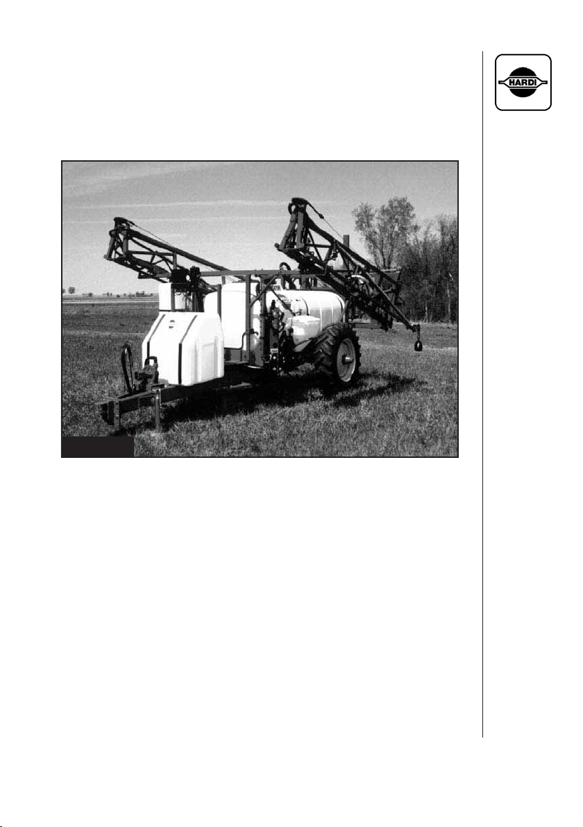
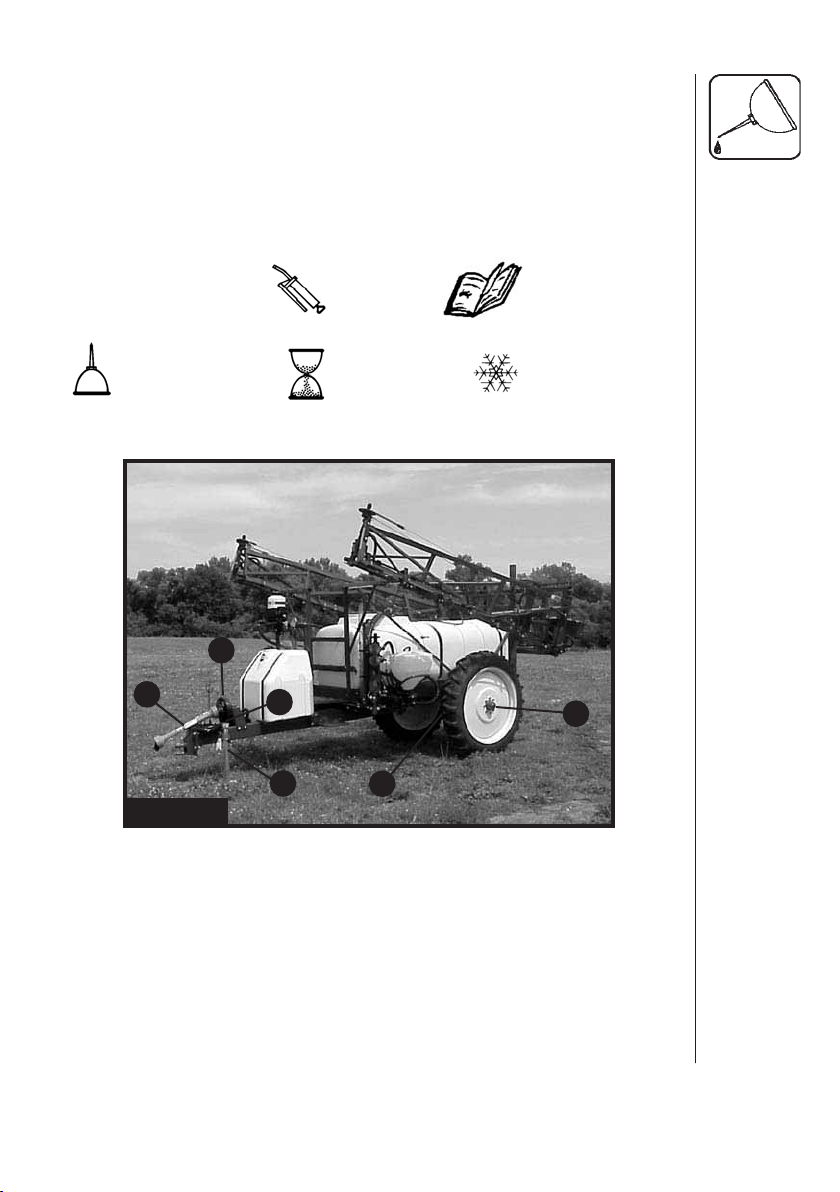
Fig. 1
Navigator HC 550M Centrifugal w/ Eagle™ Boom
5HARDI® NAVIGATOR 550M, 800M, 1000M CENTRIFUGAL OPERATOR'S MANUAL
Page 8

1.0 INTRODUCTION
The HARDI® Navigator 550M, 800M* and 1000M centrifugal models
consist of a hydraulic pump or P.T.O. driven pump with P.T.O. shaft,
frame with tank, ESC controls (Electric Control) and Manifold System.
The Navigator 550M model is available with either the hydraulic folding
Eagle™ SPB series spray boom available in 45', 50', 60' or 66' widths
or a manual fold boom (MB) available in 35', 40', 42', 45' or 50' widths.
The Navigator 800M*/1000M model is available with the hydraulic
folding Eagle™ SPC series spray boom available in 80' 88' or 90'
widths.
The tanks, made of impact proof and chemical resistant poly eth ylene,
have a purposeful design with rounded contours which allows for
efficient cleaning and draining. The tanks are designed with a large
deep sump, so that they can be completely emptied even when the
sprayer is used on slopes up to 15% inclination. A remote operated
valve drain is fi tted for effi cient draining.
The ESC control unit consists of: ON/OFF control, pressure regulating
valve, 2 1/2" pressure gauge and distribution valves with pressure
equalization.
The “Manifold System” features color coded three way valves on suction
and pressure sides of the liquid control system. It allows for safe and simple
use of the sprayer and accessories from one centralized location.
The Eagle™ coil spring suspended hydraulic series boom is available
with either 3 (HY model) or 5 (HZ model) hydraulic cylinders. The base
version being the HY model, includes boom height adjustment and
fold/unfold features all controlled from the tractor. The HZ model has all
the same features as the HY model but also includes individual wing
tilt and fold with a 'joystick' control handle. An optional electrical 'DH'
control for closed center hydraulics is available. Both versions require
single and double acting hy drau lic outlets on the tractor as well as a
12V connection for the HZ model. The MB (manual fold boom) offers
hydraulic height adjustment and hydraulic wing tilt as options.
The Navigator 800M is no longer available
*
6 HARDI® NAVIGATOR 550M, 800M, 1000M CENTRIFUGAL OPERATOR'S MANUAL
Page 9

2.0 SAFETY INFORMATION
WARNING
ALWAYS READ OPERATOR'S MANUAL BEFORE
USING EQUIPMENT
DO NOT REMOVE ANY SAFETY DEVICES OR
SHIELDS. NEVER SERVICE, CLEAN OR REPAIR A
MACHINE WHILE IT IS OPERATING
WARNING
ALWAYS WATCH FOR THIS SYMBOL TO POINT OUT
IMPORTANT SAFETY PRECAUTIONS
IT MEANS ATTENTION! BECOME ALERT!
YOUR SAFETY IS INVOLVED!
7HARDI® NAVIGATOR 550M, 800M, 1000M CENTRIFUGAL OPERATOR'S MANUAL
Page 10

RECOGNIZE SAFETY INFORMATION
This is the Safety-alert symbol. When you see
this symbol on your machine or in this manual,
be alert to the potential for personal injury.
Follow recommended precautions and safe
operating practices.
2.1 Follow Safety Instructions
- Carefully read all the safety messages in this manual and the safety
labels fi tted to the machine. Keep safety labels in good condition.
Replace missing or damaged safety labels. Be sure that new equipment components include any current safety labels. Re placement
safety labels are available from your authorized HARDI® dealer.
- Learn how to operate the sprayer and how to use the controls properly. Do not let anyone operate the machine without proper instructions.
- Keep your sprayer in proper working condition. Unauthorized modifi cations or use may impair the function and/or safety and affect the
machines life.
- If you do not understand any part of this manual and need as sistance, please contact your authorized HARDI® dealer.
2.2 Operating The Sprayer Safely
1. Read the complete manual carefully and become familiar with the
operation of the equipment before initial operation in each spraying season. Failure to do so may result in possible over or under
application of spray solution which may drastically affect crop
production and lead to personal injury.
2. Before starting the engine on the tractor unit, be sure all operating
controls are in the off or neutral position, including (but not limited
to) the hydraulic lever to operate the hydraulic driven pump, the
P.T.O. shaft and/or spray controls. Be sure the tractor power train
is disengaged.
3. Operate spray and boom functions only when seated in the
operator’s seat.
8 HARDI® NAVIGATOR 550M, 800M, 1000M CENTRIFUGAL OPERATOR'S MANUAL
Page 11

4. One of the most frequent causes of personal injury or death
results from persons falling off or being run over. Do not permit
others to ride on or in. Only one person should be working the
machine when in operation.
5. Before leaving the tractor seat, stop the engine, put all controls in
neutral, and put the transmission control lever in the park position or neutral with the brakes locked. Read the tractor operations
manual for added safety precautions.
6. P.T.O. driven equipment can cause serious injury. Before working
on or near the P.T.O. shaft, servicing or cleaning the equipment,
put P.T.O. lever in the DISENGAGE position and stop the engine.
7. Do not fold or unfold boom near overhead wires. Serious injury or
death could result if contact is made with electric wires.
8. Keep hands, feet & clothing away from moving parts.
9. Wear relatively tight and belted clothing to prevent from being
caught on some part of the machine.
10. Slow down when turning, especially with boom unfolded.
11. Always keep children away from your sprayer and/or tractor unit.
12. Before transporting the sprayer, ensure that the boom is fully
folded and fully locked into transport position. Ensure all locking
devices are fully engaged, whether hydraulic or mechanical.
13. Slow moving tractors and spray equipment can create a hazard
when on public roads. Avoid personal injury or death resulting
from any accidents by using fl ashing lights. Local regulations
may require installation of fl ashing warning lights.
14. Avoid injuries from high pressure fl uids penetrating the skin by
relieving system pressure before disconnecting hydraulics or other
lines. Ensure all fi ttings are tight before applying pressure to the
system.
15. Understand service procedures before undertaking any mainte-
nance. Never lubricate, service, or adjust the machine while it's
moving. Securely support any components before working on
them.
16. Keep all parts in good condition and properly installed. Fix dam-
aged parts immediately. Replace worn or broken parts. Remove
ex cessive buildup of grease, oil or debris.
9HARDI® NAVIGATOR 550M, 800M, 1000M CENTRIFUGAL OPERATOR'S MANUAL
Page 12

2.3 Handling Chemical Products Safely
1. Direct exposure to hazardous chemicals can cause serious injury.
These chemicals can include lubricants, coolants, paints, adhesives
and agricultural chemicals. Material Safety Data Sheets (M.S.D.S.)
are available for all hazardous chemicals which inform the user of
specifi c details including: physical and health hazards, safety procedures, and emergency response techniques.
2. Protective clothing such as rubber gloves, goggles, coveralls and
respirator must be worn while handling chemicals. All protective
clothing should be kept in excellent condition and cleaned regularly
or discarded.
3. If chemicals come in contact with any exposed skin areas, wash immediately with clean water and detergent. Never place nozzle tips or
any other components that have been exposed to chemicals to lips
to blow out obstructions. Use a soft brush to clean spray nozzles.
4. Dedicate an area to fi ll, fl ush, calibrate and decontaminate sprayer
where chemicals will not drift or run off to contaminate people, animals, vegetation, water supply, etc. Locate this area where there is
no chance of children coming in contact with this residue.
5. Decontaminate equipment used in mixing, transferring and applying
chemicals after use. Follow the instructions on the chemical label for
the correct procedure required. Wash spray residue from outside of
the sprayer to prevent corrosion.
6. Extreme care should be taken in measuring spray products. Powders
should be used in suitable sized packages or weighed accurately.
Liquids should be poured into a suitable graduated container. Keep
chemical containers low when pouring. Wear a fi ltered respirator
and let the wind blow away from you to avoid dust and/or splashes
contacting the skin or hair.
7. Store chemicals in a separate, plainly marked locked building. Keep
the chemical in its original container with the label intact.
8. Dispose all empty containers after rinsing in accordance with local
regulations & by-laws. Dispose of all unused chemicals and left over
fertilizer in an approved manner
9. Keep a fi rst aid kit and fi re extinguisher available at all times when
handling chemicals.
10 HARDI® NAVIGATOR 550M, 800M, 1000M CENTRIFUGAL OPERATOR'S MANUAL
Page 13

2.4 Local Poison Information Center
If you live anywhere in the United States, the following toll free number
will connect you to your Local Poison Information Center.
PHONE NO. 1 - 8 0 0 - 2 2 2 - 1 2 2 2
If you live outside the United States, fi nd the number for the poison control
center in your phone book and write it in the space below:
PHONE NO. _________ - _________ - _____________
Keep a list, in the space provided below, of all the chemicals that you
have in use.
1. __________________________________________________
2. __________________________________________________
3. __________________________________________________
4. __________________________________________________
5. __________________________________________________
6. __________________________________________________
7. __________________________________________________
8. __________________________________________________
9. __________________________________________________
10. __________________________________________________
11HARDI® NAVIGATOR 550M, 800M, 1000M CENTRIFUGAL OPERATOR'S MANUAL
Page 14
3.0 HOOKING UP THE SPRAYER
3.1 Clevis Hitch
WARNING:
SUPPORTED AND WHEELS BLOCKED BEFORE
ADJUSTING CLEVIS HITCH POSITION.
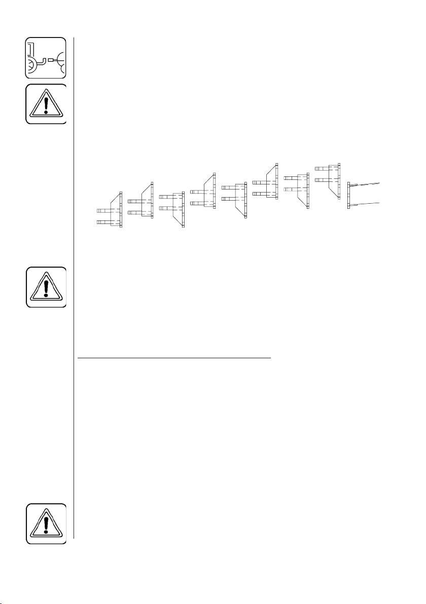
Adjusting the height of the clevis is obtained by removing the four bolts
and repositioning the clevis in one of the eight different settings (Fig. 2).
This will allow for 13" of adjustment to suit tractor drawbar height and to
maintain the sprayer tank level.
THE TRAILER TONGUE MUST BE ADEQUATELY
Fig. 2
Adjusting The Clevis Hitch
3.2 Wheel Spacing And Ground Clearance
WARNING:
ADJUSTMENTS. NEVER ATTEMPT TO ADJUST AXLES
WITH LIQUID IN TANK. ALWAYS BLOCK WHEELS ON
OPPOSITE SIDE WHEN ADJUSTING AXLES.
The wheel spacing of the trailer can be set according to the table below:
SECURELY SUPPORT THE SPRAYER DURING AXLE
Wheel Spacing & Clearance Table
Model Wheel Spacing Axle Clearance
STA 550M 60" - 88" 26"
HC 550M (24" tire) 60" - 88" 18"
HC 550M (38" tire) 60" - 88" 24"
TA 800M/1000M* 60" - 88" and 120" 20 / 27.5"
HC 800M/1000M (38“tire) 72" - 88" and 120” 26"
HC 800m/1000M (42“tire) 72" - 88" and 120” 27.5"
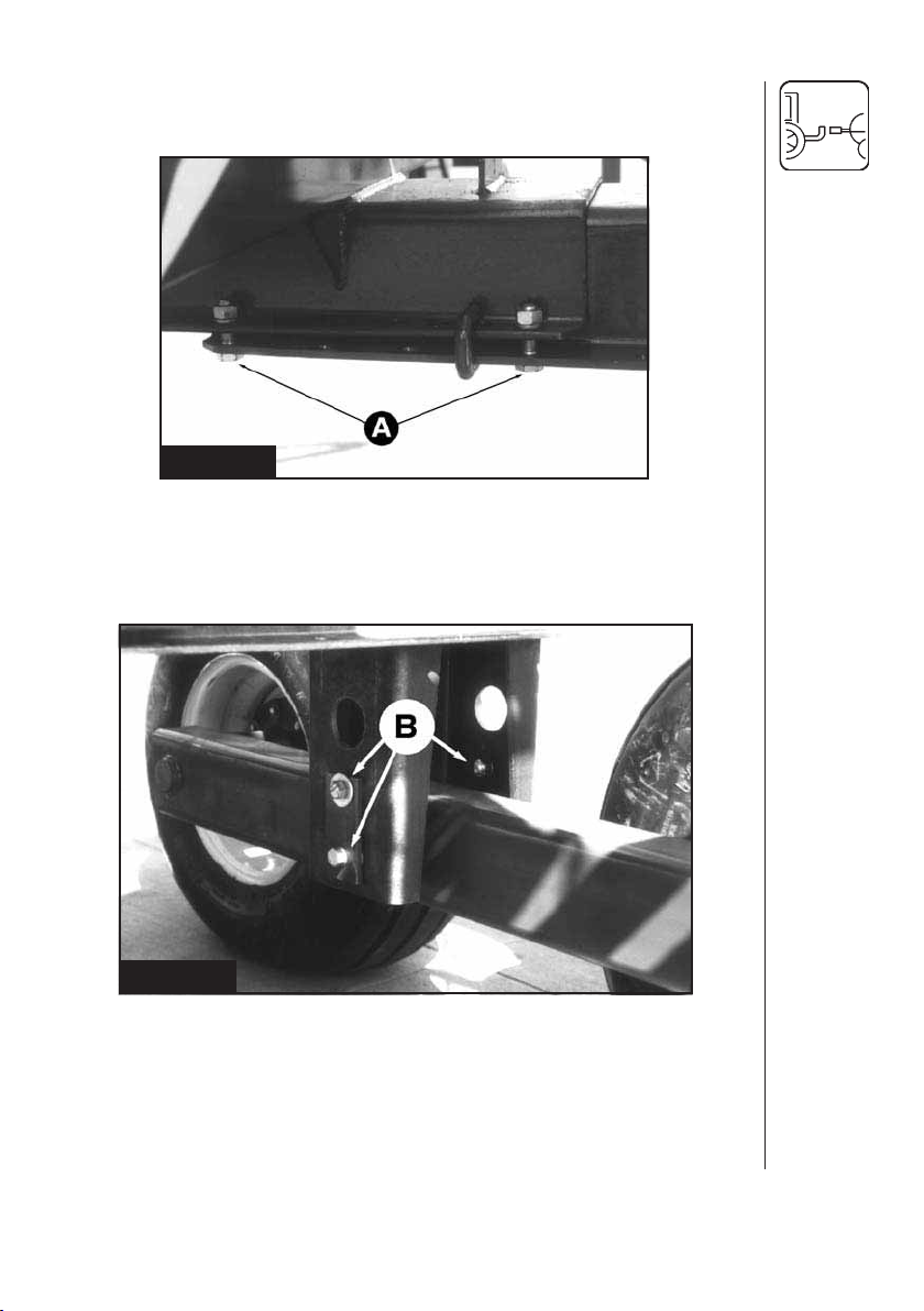
To adjust the width, remove the four bolts per side (A) (Fig. 3) and the axle
assemblies can then be pushed in or pulled out in 2" increments until the
required wheel tread is obtained. Then reinstall and refasten all bolts.
WARNING:
IT IS NOT PERMITTED TO FIT DUAL WHEELS TO ANY OF
THE AXLES ON THE NAVIGATOR M. SPRAYER MODELS.
*No longer available
12 HARDI® NAVIGATOR 550M, 800M, 1000M CENTRIFUGAL OPERATOR'S MANUAL
Page 15
Note: On 550M HC models, rims may have to be switched from one side
to the other to obtain proper wheel spacing.
Fig. 3
Ground clearance can be changed on the 800M/1000M TA (no longer
available) to either 20" or 27.5". This is done by loosening the three bolts
(B) (Fig. 4) and removing the pivot pin. Place the tandem beam at either
of the two positions and reinstall the pivot pin and bolts.
Fig. 4
Note: The HARDI® Navigator 800M/1000M model also has an optional
120" wide axle. The 120" axle is available in the single axle HC
(High Clearance). The TA (Tandem Axle) version is no longer
available. The 120" axle is a fi xed length and cannot be adjusted.
Ground clearance is the same as the standard axle systems.
13HARDI® NAVIGATOR 550M, 800M, 1000M CENTRIFUGAL OPERATOR'S MANUAL
Page 16

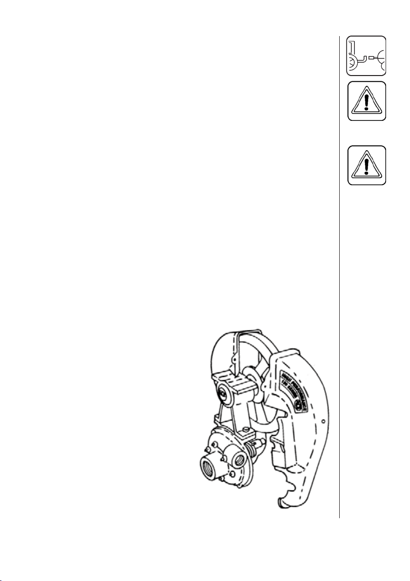
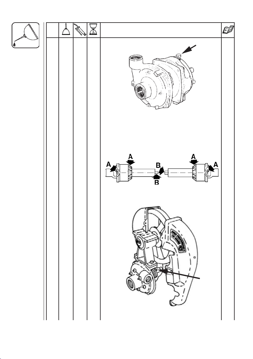
3.3 Hydraulic Driven Centrifugal Pump
WARNING:
1. Connect 3/8" or 1/2" hydraulic lines with 3/8" NPT ends to the hydraulic motor.
2. Connect the pressure line (A) (Fig.5), IN port, to the tractor outlet
port.
3. Connect the return line (B) (Fig. 5), OUT port, from the motor to the
low pressure return line on the tractor. Failure to do so may cause
the hydraulic motor seal to blow.
Note: If a low pressure return is not available, consult your tractor
4. Open the suction valve coming from the sump of the sprayer tank.
5. Bleed out all the air in the suction line by removing the plug (C)
(Fig. 5) on the top rear side of the pump and wait until there is a full
stream of fl uid coming out. Reinstall the plug.
Note: Running the centrifugal pump dry for longer than 3 seconds will
IF YOU ARE UNSURE OF THE TYPE OF TRACTOR
HYDRAULIC SYSTEM YOU HAVE, CONSULT THE
HYDRAULIC SYSTEM PUMP GUIDE AND/OR FOLLOW
THE HARDI® INSTALLATION SHEET (PART NO. #105873)
SUPPLIED WITH YOUR SPRAYER. FAILURE TO DO SO
CAN CAUSE SERIOUS DAMAGE TO YOUR TRACTOR
HYDRAULICS AND/OR THE PUMP.
dealer.
cause serious damage to the pump seal.
Fig. 5
14 HARDI® NAVIGATOR 550M, 800M, 1000M CENTRIFUGAL OPERATOR'S MANUAL
Page 17
3.4 P.T.O. Shaft Operator Safety (P.T.O. Driven Pumps Only)
WARNING:
TRANSMISSION SHAFT TO TRACTOR P.T.O. - MOST
TRACTOR P.T.O. SHAFTS CAN BE ROTATED BY
HAND TO FACILITATE SPLINE ALIGNMENT, WHEN
ENGINE IS STOPPED.
When attaching the shaft, make sure that the snap lock is FULLY
ENGAGED - push and pull shaft until it locks.
ALWAYS STOP ENGINE BEFORE ATTACHING THE
WARNING:
PROTECTION GUARDS ARE FATAL
Always keep protection guards and chains intact and make sure that
it covers all rotating parts, including CV-joints at each end of the shaft.
Do not use without protection guard.
Do not touch or stand on the transmission shaft when it is rotating
- safety distance: min 5' (1.5 meters).
Prevent protection guards from rotating by attaching the chains allowing suffi cient slack for turns.
Make sure that protection guards around tractor P.T.O. and implement
shaft are intact. Check every 40 hours.
Always STOP ENGINE and remove the ignition key before carrying out
maintenance or repairs to the transmission shaft or implement.
Make sure that belt guards on belt-driven
pumps are intact. Never operate without
belt guards.
ROTATING TRANSMISSION SHAFTS WITHOUT
.
15HARDI® NAVIGATOR 550M, 800M, 1000M CENTRIFUGAL OPERATOR'S MANUAL
Page 18
3.5 Installation Of P.T.O. Shaft
WARNING:
Initial installation of the shaft is done as follows:
1. Attach sprayer to tractor and set sprayer in the position with shortest
distance between the tractor and sprayer pump P.T.O. shafts.
2. Stop engine and remove ignition key.
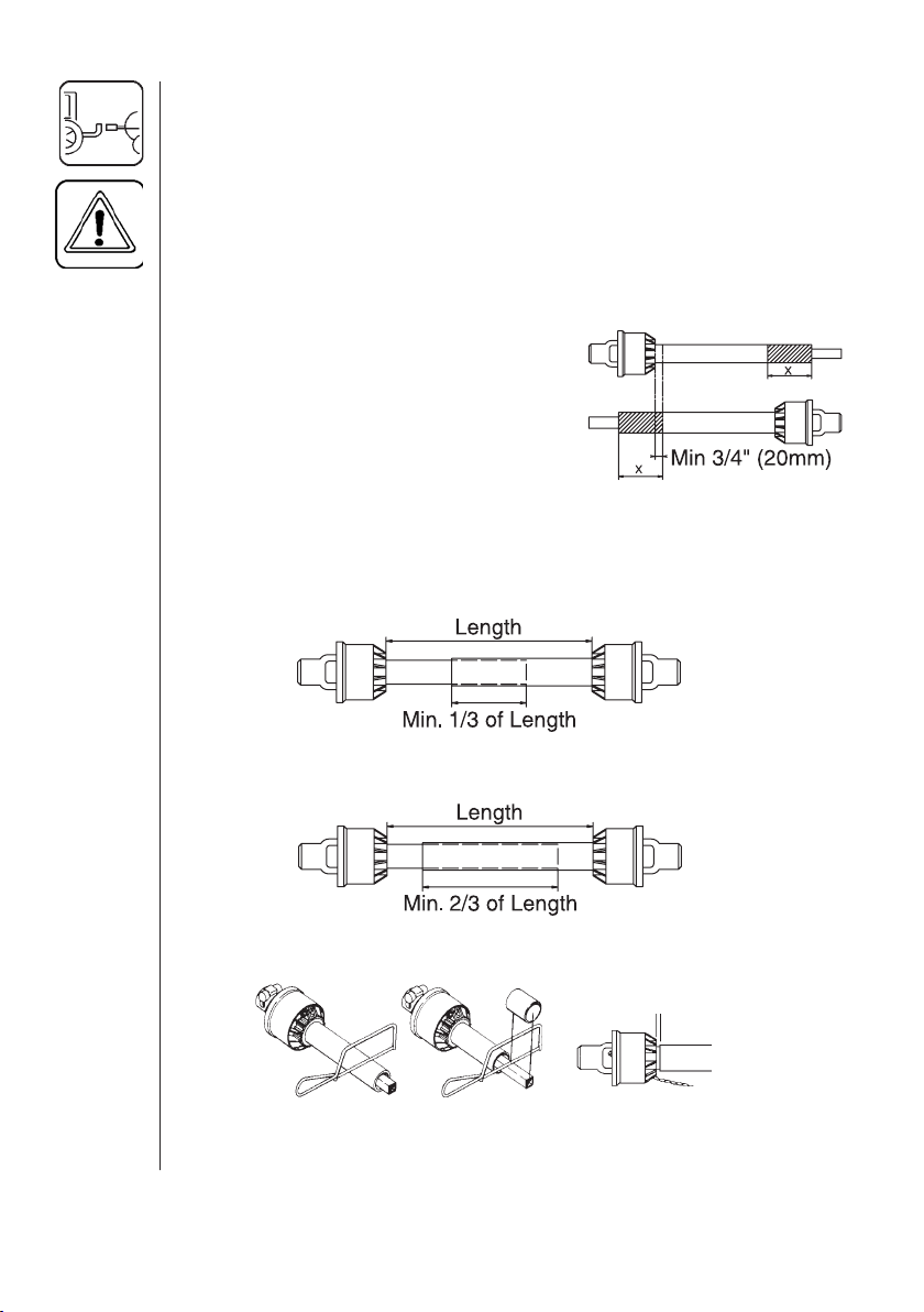
3. If P.T.O. shaft must be shortened, the
shaft is pulled apart. Fit the two shaft
parts at tractor and sprayer pump and
measure how much it is necessary to
shorten the shaft. Mark the protection
guards.
Note: The minimum allowable overlap for the shaft depends on the pump
Pump with 6 splines (540 r.p.m.)
The shaft must always have a minimum overlap of 1/3 the length.
THE P.T.O. SHAFT ANGLE WILL CHANGE WHEN RAISING
AND LOWERING THE AXLE SYSTEMS AND/OR CLEVIS. TO
PREVENT EXCESSIVE LOADING AND BINDING ON THE P.T.O.
SHAFT, IT MAY BE ADVISABLE TO LEAVE THE P.T.O. SHAFT
DISCONNECTED UNTIL THIS OPERATION IS COMPLETED.
THEN THE P.T.O. SHAFT ADJUSTMENTS CAN BE MADE.
model.
(
P.T.O. Driven Pumps Only
)
Fig. 6
Pump with 21 splines (1000 r.p.m.)
The shaft must always have a minimum overlap of 2/3 the length.
Fig. 7
4. The two parts are shortened equally. Use a saw, and fi le the profi les
afterwards to remove burrs (Fig. 8).
min. 3/4" (20mm)
Fig. 8
5. Grease the profi les, and assemble male and female parts again.
6. Fit the shaft to tractor and sprayer pump.
16 HARDI® NAVIGATOR 550M, 800M, 1000M CENTRIFUGAL OPERATOR'S MANUAL
Page 19
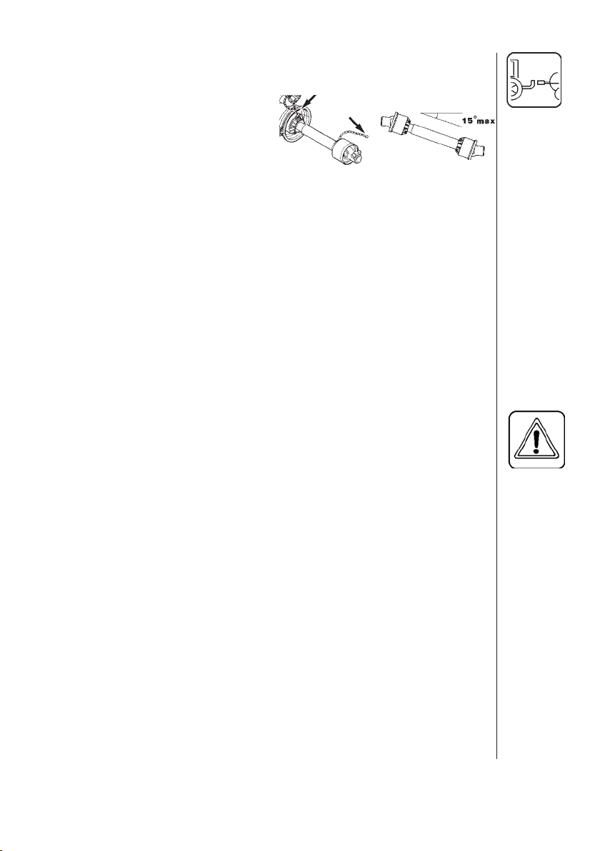
Note: Female part towards tractor. Fit the chains to prevent the protec-
tion guards r
7. To ensure long life of the P.T.O.
shaft, try to avoid working angles
greater than 15° (Fig. 9).
otating with the shaft.
Fig. 9
3.6 Hydraulic Requirements
Eagle™ Boom:
Hydraulic booms need one single outlet for the lift function of the spray
boom and one double outlet for the folding function. Note that the hydraulic
system requires an oil capacity of approximately .8 GPM (3 LPM) and a
minimum pressure of 1,950 PSI (130 bar).
Hydraulic Driven Centrifugal Pump:
The pump motor needs one single outlet and a low pressure return outlet
on the tractor.
Note: The hydraulic driven pump system requires an oil capacity of 7
GPM (26.5 LPM)and a minimum pressure of 1000 PSI (67 bar).
BE SURE TO HOOK UP HYDRAULIC LINES PROPERLY!
ENSURE HYDRAULIC LINES HAVE NOT BEEN DAMAGED DURING
SHIPPING.
ESCAPING HYDRAULIC FLUID UNDER PRESSURE CAN
PENETRATE THE SKIN CAUSING SERIOUS INJURY. AVOID THIS
HAZARD BY RE LIEVING PRESSURE BEFORE DISCONNECTING
HYDRAULIC LINES.
ENSURE ALL CONNECTIONS ARE TIGHT BEFORE APPLYING
PRESSURE, SEARCH FOR LEAKS WITH A PIECE OF
CARDBOARD, NOT YOUR HANDS!
IMPROPER HOOK-UP CAN CAUSE DANGEROUS BOOM
MOVEMENTS AND/OR DAMAGE TO THE SPRAYER HYDRAULICS.
DO NOT ALLOW ANYONE NEAR A HYDRAULIC BOOM IN
OPERATION.
ALWAYS SHUT TRACTOR OFF WHEN CONNECTING, SERVICING
OR ADJUSTING BOOM.
17HARDI® NAVIGATOR 550M, 800M, 1000M CENTRIFUGAL OPERATOR'S MANUAL
Page 20
Hydraulic Hook-up For Booms
1. Attach the heavier (3/8") hydraulic hose for the boom lift to the tractor's
single acting outlet.
Note: Required on both Eagle™ booms & MB (HL) booms.
2. Attach the lighter (1/4") hydraulic hoses for boom folding & HZ tilt to
the tractor's double acting outlet.
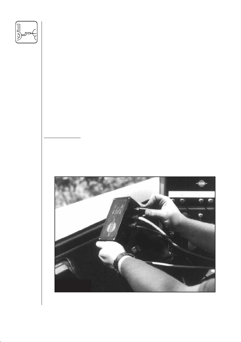
3.7 Control Box For ESC Control Unit
The control box for the ESC control unit should be mounted at a
convenient place in the tractor cab. The control box has 4 screw holes
in the back cover, which need to be drilled out for mounting on a fl at
surface, use the optional mount kit #728739 if required. There should
be a minimum of an 8 amp fuse protecting this circuit.
Power requirement is 12 volt DC.
Note polarity:
Brown pos. (+)
Blue neg. (-)
Use the optional HARDI® Electric 12 volt outlet box #817925 if more than
one power outlet is required.
Fig. 10
12-volt junction box for 12-volt hook-up: ESC controls, HARDI
®
HM1500/HC2500, Foam Marker, Boom Hydraulic Controls, etc.
18 HARDI® NAVIGATOR 550M, 800M, 1000M CENTRIFUGAL OPERATOR'S MANUAL
Page 21
4.0 OPERATING INSTRUCTIONS
4.1 Operating The Boom
BEFORE UNFOLDING THE BOOM, IT IS IMPORTANT TO HAVE
THE SPRAYER HOOKED TO THE TRACTOR TO PREVENT
OVER BAL ANCING THE SPRAYER. ONLY THEN LIFT THE BOOM
OFF THE TRANSPORT BRACKETS WHICH HOLD IT IN THE
TRANSPORT POSITION.
ENSURE THAT BOOMS ARE IN THE TRANSPORT POSITION
BEFORE UNHOOKING THE SPRAYER FROM THE TRACTOR.
THE HYDRAULIC SYSTEM SHOULD BE CHECKED VERY
CAU TIOUSLY THE FIRST TIME OF OPERATION; THERE MAY
BE AIR IN THE SYSTEM AND THIS COULD CAUSE VIOLENT
MOVE MENTS OF THE BOOM. ENSURE THAT NO PERSONS OR
OBJECTS ARE IN THE WAY WHILE CHECKING THE SYSTEM.
FOR INFORMATION ON BOOM ADJUSTMENT SEE THE
APPRO PRIATE BOOM OPERATOR'S MANUAL.
4.2 Filling The Main Tank
Water is fi lled into the tank by removing the tank lid located at front
center of sprayer tank. It is recommended to use water as clean as
possible for spraying purposes. Always fi ll water through the strainer
basket to prevent foreign particles from entering the tank.
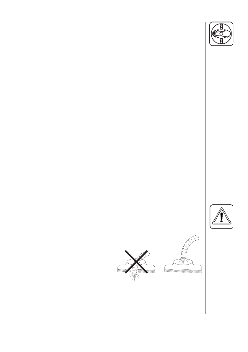
WARNING:
DO NOT LET THE FILLING HOSE ENTER THE TANK.
KEEP IT OUTSIDE THE TANK, POINTING TOWARDS
THE FILLING HOLE (FIG. 11). IF THE END OF THE
HOSE IS BENEATH THE SURFACE OF THE TANK
CONTENTS AND THE WATER PRESSURE
DROPS AT THE WATER SUPPLY PLANT,
CHEMICALS MAY
BE SIPHONED BACK
AND CON TAM INATE
THE WATER SUPPLY
LINES.
Fig. 11
4.3 Filling the Flush Tank (If fi tted)
Remove the tank lid, fi ll with clean water and replace lid.
19HARDI® NAVIGATOR 550M, 800M, 1000M CENTRIFUGAL OPERATOR'S MANUAL
Page 22
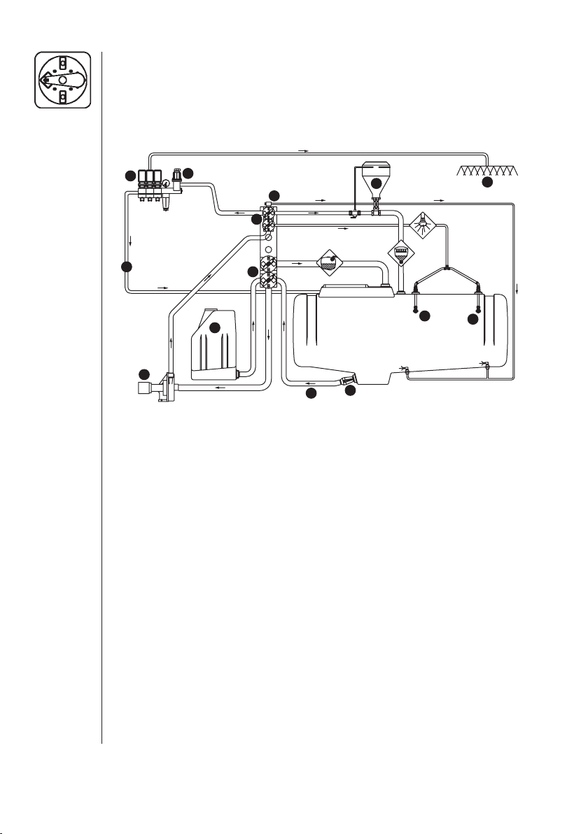
4.4 Manifold Sprayer Plumbing Diagram
Review and study the following diagram. By fol low ing the fl ow through
the diagram, you will better un derstand the various functions of your
spray er system.
ESC (with optional equipment)
8
10
3
7
5
4
2
11
1
12
13
6
9
13
The di agram shows the Standard plumbing with examples of op tions
avail able.
Function Diagram
1. Suction line 8. Distribution valves
2. Suction manifold (black) 9. Spray boom
3. Pump 10. Pressure equalization return
4. Pressure man ifold (green) 11. Flush tank*
5. Pressure Agitation 12. HARDI® chemical inductor*
6. On/Off valve 13. Tank rinse nozzles*
7. Pressure adjustment
*optional equipment
4.5 Manifold Sys tem
The “Manifold Sys tem” is lo cated at the left hand side of the sprayer,
per mitting op er ation of most of the (fi t ted) ac cessories from one po sition.
The modular design of the Man ifold sys tem allows the easy addition of
many ac cessories to the plumb ing sys tem of the spray er. The system
can be ex panded to a maximum of 4 valves on the pres sure side and 2
valves on the suction side.
20 HARDI® NAVIGATOR 550M, 800M, 1000M CENTRIFUGAL OPERATOR'S MANUAL
Page 23
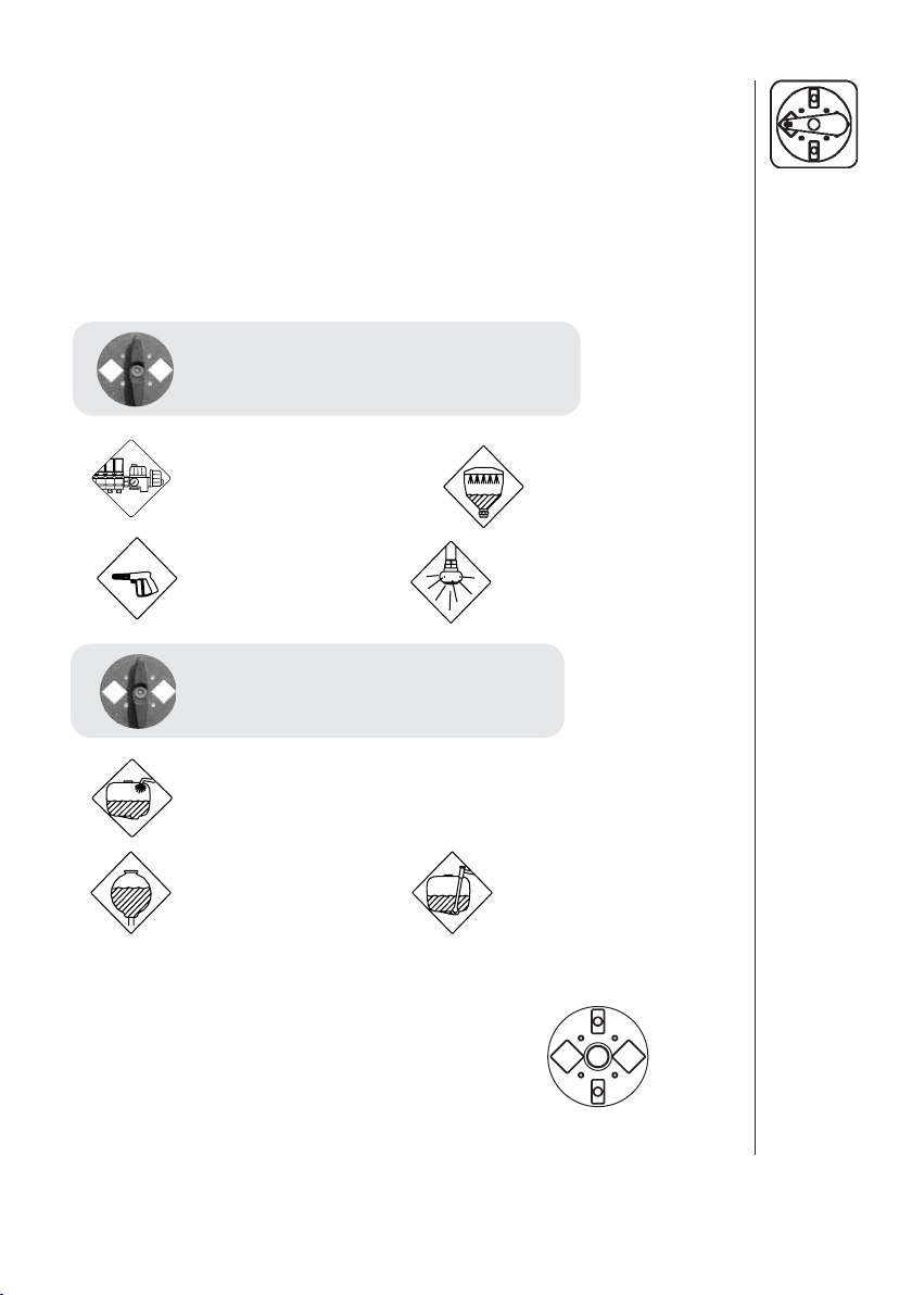
The manifold valve faces are colored discs for easy identifi cation. The
green face iden tifi es the pressure man ifold, the black disc identifi es the
suction manifold.
Symbols are fi tted to the faces of the 3 way valves in dicating the di rection
of fl ow of the liq uid.
An explanation of the sym bols is as fol lows:
Green Disc = Pres sure Valve
• To ESC Control
• To Hose Reel/Spray
Gun
Black Disc = Suction Valve
• Quick Fill
• From Flush Tank • From Main Tank
A function is activated/opened
by turning the handle towards
the desired function
• To Chemical Filler
• To Tank Rinsing noz zle
Closed
Function
Open
21HARDI® NAVIGATOR 550M, 800M, 1000M CENTRIFUGAL OPERATOR'S MANUAL
Page 24
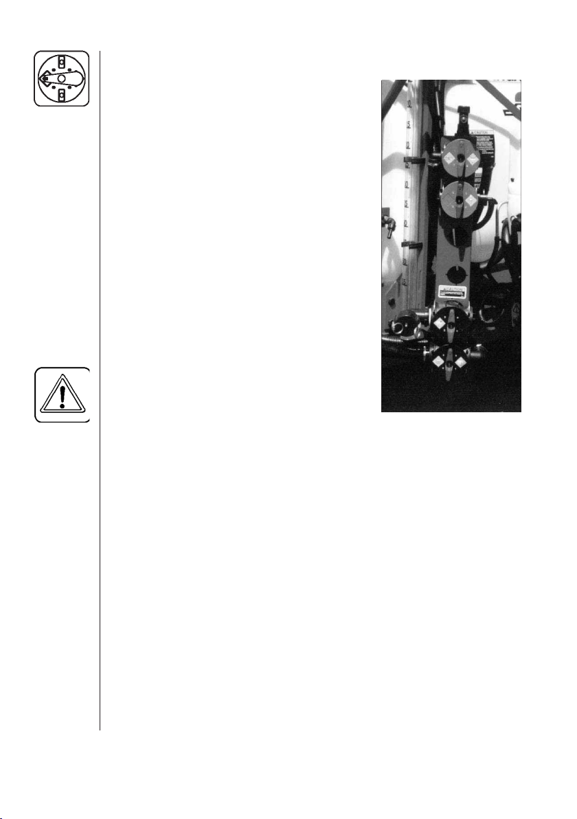
4.6 Manifold Operating In structions
The green pres sure valves and the black
suction valves have 4 po sitions. Two
positions are for op tions. The oth er two are
marked “O” in dicating the valve is closed.
The ar row on the han dle in dicates which
position is se lected.
Green Pressure Valves
To select the optional equip ment, the
handle is turned so the ar row and there by
liquid is di rected to the op tional extra
instead of the ESC operating unit. When
spray ing is to re sume, turn the handle so
the ESC operating unit is selected. The
other handles are turned to “O”. If all the
green pressure valves are closed, the
centrifugal pump will be dead headed.
WARNING
Black Suction Valves
Turn the handle so the arrow points to wards the selected op tional
equipment (e.g. Flush Tank). To re sume suction from the main tank,
the arrow must point to wards the main tank. Re maining valve must be
closed.
Note: The quick fi ll valve (if fi tted) is not connected to the manifold
Electric Op erated MANIFOLD valves (if fi t ted)
One or more MANIFOLD valves can be elec tri cally op er ated via a
control box in the tractor cab. In case of an emergency, these can be
oper ated man ually only when the 12V power to the valve motor is
disconnected fi rst.
22 HARDI® NAVIGATOR 550M, 800M, 1000M CENTRIFUGAL OPERATOR'S MANUAL
: IF THE CENTRIFUGAL PUMP
IS DEAD HEADED FOR A
LONG PERIOD OF TIME,
THE PUMP CAN OVER HEAT
AND CAUSE DAMAGE TO
THE PUMP SEAL’S.
system and is not affected by the operation of the main tank
suction valve.
Manifold System Valves
Fig 12
Page 25
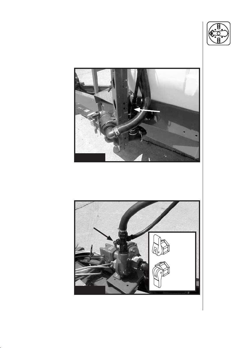
4.7 Operation of Centrifugal Bypass Kit (Early models only)
The Centrifugal Bypass Kit is designed to improve the priming of the
Centrifugal pumps.
1. Before starting the pump, fi ll the main tank and release any trapped
air in the system by holding valve (A) (Fig. 13) open for several
seconds.
A
Fig. 13
Note: Valves (A) and (B) are only present when a Centrifugal Bypass
Kit has been installed.
2. Flip valve (B) (Fig. 14) to the "open" position and then start the pump
(See Section 4.8).
B
OPEN
CLOSED
Fig. 14
3. Once the pump is "primed", valve (B) (Fig. 14) may be closed.
23HARDI® NAVIGATOR 550M, 800M, 1000M CENTRIFUGAL OPERATOR'S MANUAL
Page 26

4.8 Adjustment Of The ESC Controls
1. Adjustment screw for constant boom
pressure
2. Pressure control valve
3. Distribution valves
4. System pressure gauge
5. System pressure fi lter
Fig. 15
Fig. 16
ESC Remote Control Box
A. Master operating switch for main ON/OFF of boom section valves
B. Operating switches for individual ON/OFF of boom section valves
C. Pressure control switch to lower or raise nozzle pressure
1. Choose the correct nozzle (Section 4.14). Make sure that all the
nozzles are the same type and capacity.
2. With the tractor in neutral, engage the tractor hydraulic lever (or
P.T.O.) to start the pump. Adjust the R.P.M.'s until the number of
revolutions corresponds to the intended traveling speed.
3. ON/OFF switch (A) (Fig. 16) is "ON" against green symbol.
4.
All boom section valve switches (B) (Fig. 16) are also "ON" against
green symbol.
5. Hold pressure regulating switch (C) (Fig. 16) to (-) until handle (2)
(Fig. 15) stops rotating, this will be the "minimum pressure" setting.
6. Hold pressure regulating switch (C) (Fig. 16) to (+) until desired
pressure is shown on the pressure gauge (4) (Fig. 15).
24 HARDI® NAVIGATOR 550M, 800M, 1000M CENTRIFUGAL OPERATOR'S MANUAL
Page 27

4.9 Adjustment of Constant Pressure
Note: Adjust the constant boom section pressure one section at a time
as follows: (Start with the valve turned closed before adjusting).
1. Shut-off the fi rst boom section valve switch (B) (Fig. 16).
2. Turn the adjusting screw (1) (Fig. 15) until the control unit pressure
gauge (4) (Fig. 15) again shows the same pressure as set in step 6
(Section 4.8). (Turn the screw clockwise for higher pressure, coun-
terclockwise for lower pressure).
3. Turn the boom section valve switch (B) (Fig. 16) back on.
4. Repeat steps 1 through 3 for the remaining boom section valves.
Note: Hereafter adjustment of the constant boom pressure will only
be needed if you change to nozzles with other capacities, but
not required if only changing pressure or application rate using
the same nozzles.
5. Operating the control unit while driving: In order to shut off the entire
boom, turn ON/OFF switch to "Off" position (A) (Fig. 16). This returns all
the pump outputs to the tank through the return system. The diaphragm
antidrip valves ensures instantaneous closing of all noz zles.
In order to shut off one or more sections of the boom, switch one or
more unneeded boom section valves (B) (Fig. 16) to "Off" position. The
constant pressure device ensures that the pressure does not increase
in the sections which are still operating.
In case of electrical failure, it is still possible to manually override all functions
of the operating unit. To operate manually, disconnect the multiplug from
the ESC control box fi rst and operate the handles by hand. It is possible
to change pressure, turn boom sections on or off, or shut off the complete
control unit manually.
IMPORTANT:
When the sprayer is stored, the ESC control box and
the multiplug must be protected against moisture and dirt. A plastic
bag may be used to protect the multiplug. Store the control box in
a clean dry place.
25HARDI® NAVIGATOR 550M, 800M, 1000M CENTRIFUGAL OPERATOR'S MANUAL
Page 28

4.10 Agitation Adjustment (Agitation nozzles only)
Agitation is necessary to keep the solution in your tank properly mixed.
Consult your chemical supplier for the recommended amount of
agitation.
In general, maximum agitation is required but some products tend to foam
easily. To reduce foaming in some instances anti-foaming agents may
be added to the tank (Refer to chemical label). When running low liquid
levels in the tank, agitation may be reduced to facilitate pump priming
and avoid pressure fl uctuations. Make sure that you have adjusted the
agitation properly before sprayer calibration.
Turning the agitation valve (A) (Fig. 17) clockwise will reduce the agitation
fl ow. Turning the valve counter clockwise will increase the agitation fl ow.
A
Fig. 17
26 HARDI® NAVIGATOR 550M, 800M, 1000M CENTRIFUGAL OPERATOR'S MANUAL
Page 29

4.11 Adding Chemicals
Chemicals can be fi lled into the tank two different ways:
A. Through the tank lid.
B. By using the HARDI® CHEMICAL FILLER device.
WARNING:
Always use the personal pro tection stated on the
A. Filling through the tank lid
The chemicals are fi lled through the tank lid - Note instructions on the
chemical container!
1. Fill the main tank with clean water, allowing space for the addition of
chemicals (See Section 4.2).
2. Make sure the ESC operating unit main on/off switch is in the "Off"
position (See Section 4.8).
3. Turn the top green pressure manifold
handle to the ESC control symbol.
4. Turn the bottom black suction manifold
handle to the Main Tank symbol.
5. Any other manifold valves should be in the "Off" position.
6. Turn the agitation valve (A) (Fig. 17) counter clockwise all the way
out for maximum agitation.
7. Engage the pump and set P.T.O. revolutions to 540 r.p.m. or 1000
r.p.m. (depending on pump model).
8. Add the chemicals through the main tank hole.
9. When the spray liquid is well mixed, it may be sprayed on the crop.
Leave the agitation valve at maximum agitation so the spray liquid is
continuously ag itated while spraying.
Be careful not to slip or splash chem icals when
carrying chemicals up to the tank lid.
chemical container and as a minimum, always use
gloves, face pro tection shield and coveralls.
27HARDI® NAVIGATOR 550M, 800M, 1000M CENTRIFUGAL OPERATOR'S MANUAL
Page 30

B. Filling with the HARDI® CHEMICAL FILLER (optional)
The HARDI® CHEMICAL FILLER is located directly behind the
Manifold System Valves.
Operating with Liquid-based chemicals
1. Make sure the ESC operating unit main on/off switch is in the "Off"
position (See Section 4.8).
2. Fill the fl ush tank (optional) with clean water and fi ll the main tank at
least 1/3 with clean water (unless something else is stated on the
chemical container label). (See Sections 4.2, 4.3)
3. Turn the top green pressure manifold
handle to the Chem Fill symbol.
4. Turn the bottom black suction manifold
handle to the Main Tank symbol.
5. Any other manifold valves should be in the "Off" position.
6. Turn the agitation valve (A) (Fig. 17) counter clockwise all the way
out for maximum agitation.
7. Make sure the bottom valve (A) (Fig. 18) is closed on the HARDI
®
CHEMICAL FILLER.
8. Engage the pump and set P.T.O. revolutions to 540 r.p.m. or 1000
r.p.m. (depending on pump model).
9. Open the HARDI® CHEMICAL FILLER lid.
10. Measure the correct quantity of chemical and fi ll it into the hopper.
Note: The measuring scale in the hopper can only be used if the
sprayer is parked on level ground. It is recommended to use a
measuring jug for best accuracy.
B
C
A
Fig. 18
28 HARDI® NAVIGATOR 550M, 800M, 1000M CENTRIFUGAL OPERATOR'S MANUAL
Page 31

11. Open the bottom valve (A) (Fig. 18) to transfer the chemical to the
main tank.
12. If the chemical container is empty, it can be rinsed by using the Bag
& Bottle Rinse (optional). Place the container over the multi-hole
nozzle and press the lever (B) (Fig. 18).
WARNING: Do not press lever (B) (Fig. 18) unless the multi-hole
nozzle is covered by a container to avoid spray liquid
hitting the operator.
IMPORTANT:
If the bottom black manifold valve is turned to MAIN
TANK, the Bag & Bottle Rinse uses diluted spray solution from the
main tank to rinse containers of concentrated chemicals. Always
rinse the chemical containers with clean water several times until
they are clean before disposal. Turn the bottom black manifold valve
to FLUSH TANK (optional) to use clean water to rinse the chemical
containers.
13. Engage the hopper rinsing device by opening valve (C) (Fig. 18).
14. Close valve (C) (Fig. 18) when the hopper is rinsed.
IMPORTANT:
If the bottom black manifold valve is turned to MAIN
TANK, the hopper uses diluted spray solution from the main tank
to rinse the hopper of concentrated chemicals. Always rinse the
hopper with clean water when fi nished spraying. Turn the bottom
black manifold valve to FLUSH TANK (optional) to use clean water
to rinse the chemical containers.
15. Close valve (A) (Fig. 18) and the chemical hopper lid. Turn the
bottom black manifold valve back to MAIN TANK (if fl ush tank was
used). Finish fi lling main tank with clean water to desired amount.
When the spray liquid is well mixed, it may be sprayed on the crop.
Leave the agitation valve at maximum agitation so the spray liquid
is continuously ag itated while spraying.
29HARDI® NAVIGATOR 550M, 800M, 1000M CENTRIFUGAL OPERATOR'S MANUAL
Page 32

Operating with Powder-based chemicals
1. Make sure the ESC operating unit main on/off switch is in the "Off"
position (See Section 4.8).
2. Fill the fl ush tank (optional) with clean water and fi ll the main tank at
least 1/2 with clean water (unless something else is stated on the
chemical container label). (See Sections 4.2, 4.3)
3. Turn the top green pressure manifold
handle to the Chem Fill symbol.
4. Turn the bottom black suction manifold
handle to the Main Tank symbol.
5. Any other manifold valves should be in the "Off" position.
6. Turn the agitation valve (A) (Fig. 17) counter clockwise all the way
out for maximum agitation.
7. Engage the pump and set P.T.O. revolutions to 540 r.p.m. or 1000
r.p.m. (depending on pump model).
8. Open the bottom valve (A) (Fig. 19) on the HARDI® CHEMICAL
FILLER and open the lid.
9. Engage the hopper rinsing device by opening valve (C) (Fig. 19).
10. Measure the correct quantity of chemical and sprinkle it into the
hopper as fast as the rinsing device can fl ush it down.
B
C
A
Fig. 19
30 HARDI® NAVIGATOR 550M, 800M, 1000M CENTRIFUGAL OPERATOR'S MANUAL
Page 33

11. If the chemical container is empty, it can be rinsed by using the Bag
& Bottle Rinse (optional). Fit the bag bracket and place the powder
bag over the multi-hole nozzle and press the lever (B) (Fig. 19).
WARNING: Do not press lever (B) (Fig. 19) unless the multi-hole
nozzle is covered by a container to avoid spray liquid
hitting the operator.
IMPORTANT:
If the bottom black manifold valve is turned to MAIN
TANK, the Bag & Bottle Rinse uses diluted spray solution from the
main tank to rinse containers of concentrated chemicals. Always
rinse the chemical containers with clean water several times until
they are clean before disposal. Turn the bottom black manifold valve
to FLUSH TANK (optional) to use clean water to rinse the chemical
containers.
12. Close valve (C) (Fig. 19) when the hopper is rinsed.
IMPORTANT:
If the bottom black manifold valve is turned to MAIN
TANK, the hopper uses diluted spray solution from the main tank
to rinse the hopper of concentrated chemicals. Always rinse the
hopper with clean water when fi nished spraying. Turn the bottom
black manifold valve to FLUSH TANK (optional) to use clean water
to rinse the chemical containers.
13. Close valve (A) (Fig. 19) and the chemical hopper lid. Turn the
bottom black manifold valve back to MAIN TANK (if fl ush tank was
used). Finish fi lling main tank with clean water to desired amount.
When the spray liquid is well mixed, it may be sprayed on the crop.
Leave the agitation valve at maximum agitation so the spray liquid
is continuously ag itated while spraying.
31HARDI® NAVIGATOR 550M, 800M, 1000M CENTRIFUGAL OPERATOR'S MANUAL
Page 34
4.12 Use of Flush Tank and Rinse Nozzles (optional)
The incorporated fl ush tank can be used for two different purposes
A. In-fi eld diluting of remaining spray liquid residue in the spraying
circuit for spraying the liquid in the fi eld, before cleaning the sprayer.
1. Empty the sprayer as much as possible. Turn the agitation valve (A)
(Fig. 17) clockwise all the way in to close agitation valve and spray
until air comes out of all nozzles.
Note: Do not run pump dry for longer than 3 seconds. Otherwise
severe damage to the pump will occur.
2. Remove the tank fi lter basket.
3. Turn the optional green pressure manifold
handle to the Tank Rinse symbol.
4. Turn the bottom black suction manifold
handle to the Flush Tank symbol.
5. Make sure any other manifold valves are in the "Off" position.
6. Engage and set pump at approximately 300 r.p.m.
7. When rinsing water corresponding to approximately 10 times the
spray liquid residue is used, turn the bottom black suction manifold
handle to the Main Tank symbol and operate all valves so all hoses
and components are rinsed.
8. Spray the liquid in the fi eld you have just sprayed.
9. Repeat steps 3-8 until the fl ush tank is empty.
WARNING: The rinse nozzles cannot always guarantee a 100%
cleaning of the tank. Always clean manually with a
brush afterwards, especially if crops sensitive to
the chemical just sprayed are going to be sprayed
afterwards.
32 HARDI® NAVIGATOR 550M, 800M, 1000M CENTRIFUGAL OPERATOR'S MANUAL
Page 35

B. Rinsing the pump, operating unit, spray lines, etc. In case of
interruption in spraying before main tank is empty (e.g. due to rain, etc.).
1. Turn the agitation valve (A) (Fig. 17) clockwise all the way in to close
agitation valve.
2. Make sure the ESC operating unit main on/off switch is in the "On"
position and that all individual on/off boom section switches are in
the "On" position (See section 4.8).
3. Turn the top green pressure manifold
handle to the ESC control symbol.
4. Turn the bottom black suction manifold
handle to the Flush Tank symbol.
5. Make sure any other manifold valves are in the "Off" position.
6. Engage the pump and spray water from the fl ush tank in the fi eld
until all nozzle tubes/nozzles are fl ushed with clean water.
7. Disengage pump. Turn all manifold valves to the "Off" position.
33HARDI® NAVIGATOR 550M, 800M, 1000M CENTRIFUGAL OPERATOR'S MANUAL
Page 36
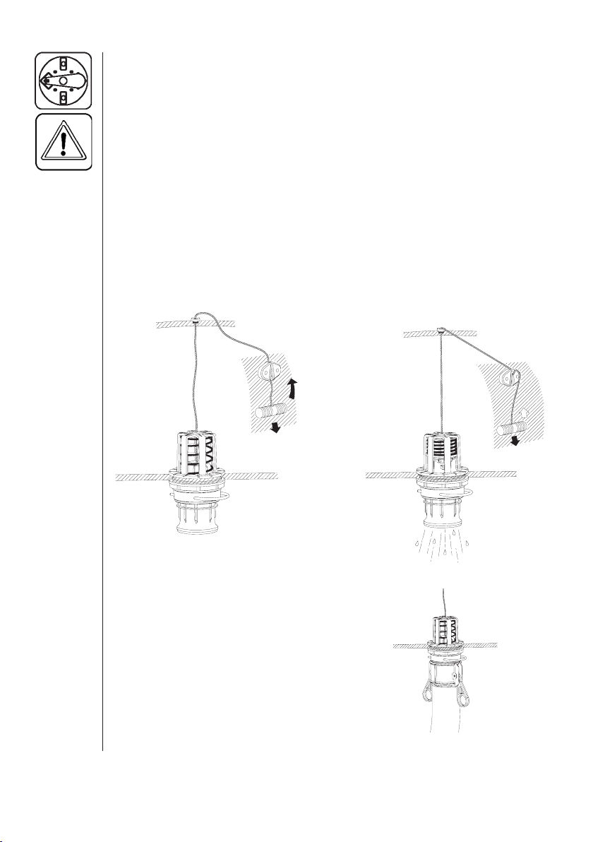
4.13 Operation Of The Tank Drain Valve
WARNING:
DISPOSAL OF WASTE IS DONE ACCORDING TO
CHEMICAL LABEL INSTRUCTIONS AND LOCAL
REGULATIONS.
Pull the string at left hand side of the tank to open the drain valve. The
valve is spring loaded to close it, but can be kept open by pulling the
string out-and upwards in the V-shaped slot (Fig. 20).
To release and close the drain valve again, pull the string downwards
and the valve will close automatically (Fig. 20).
BEFORE USING THE TOP DRAIN, VERIFY THAT
Fig. 20
If draining residues, e.g. liquid fertilizer into
a reservoir, a snap-coupler with hose can
rapidly be connected to the drain valve
and the liquid safely drained.
34 HARDI® NAVIGATOR 550M, 800M, 1000M CENTRIFUGAL OPERATOR'S MANUAL
Page 37
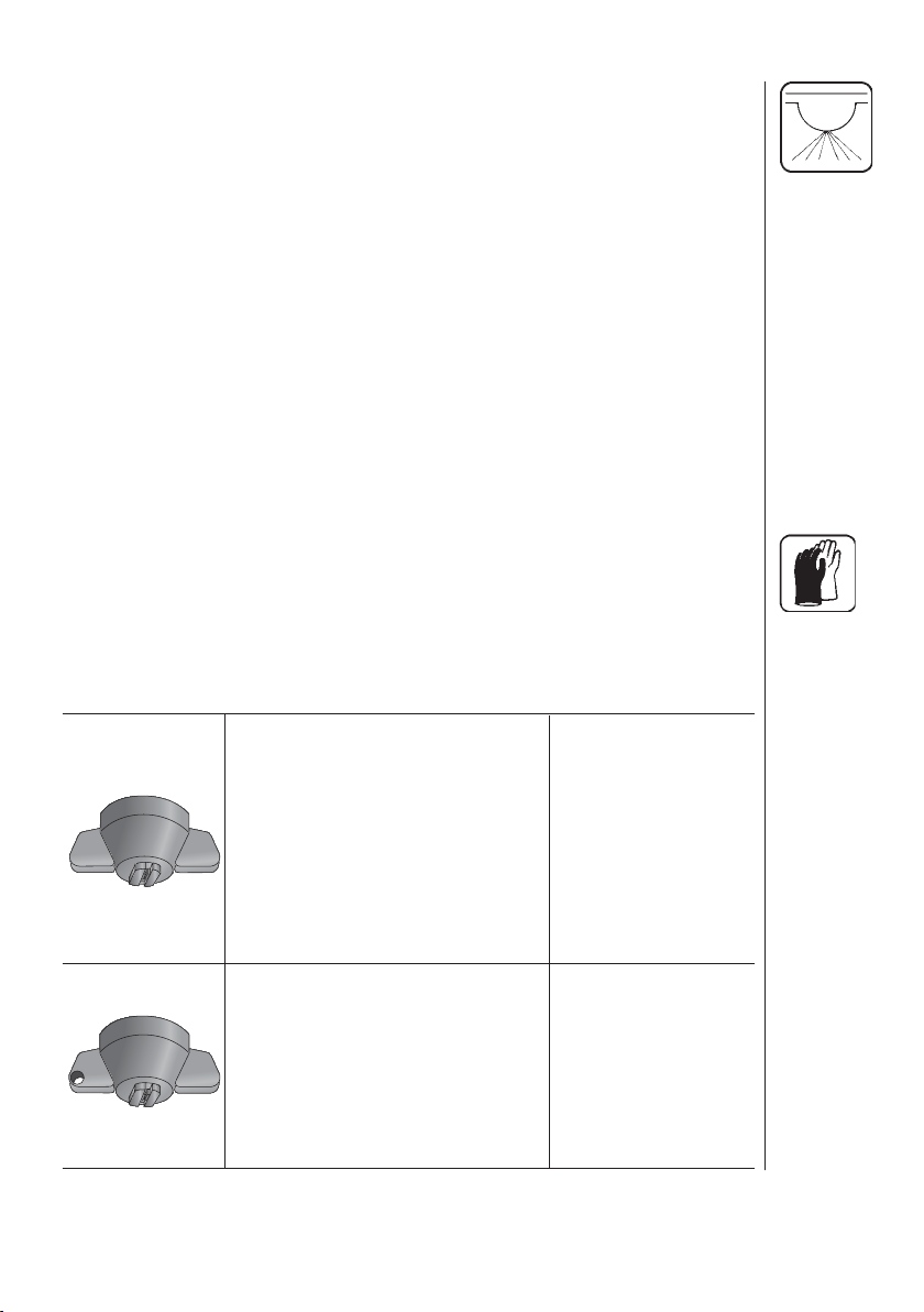
4.14 Nozzle Selection
Correct selection of nozzle and calibration of the sprayer are critical to
achieve accurate and cost effective use of farm crop protection products.
Your HARDI® sprayer has been supplied with 110° fl at spray Red ISO
Color Tips™ that will apply approximately 20 U.S. GPA at 30 PSI and
5 MPH.
The 110° fl at spray nozzle was chosen rather than the 80 degree
nozzle for two reasons: 1- It may be used at a lower minimum height
which reduces the risk of wind drift; 2- it's greater overlap permits better uniformity of spray distribution, particularly if boom height varies on
rough ground. Normal boom height setting with 110° nozzles is 18" to
20" above the crop or weeds, whichever is taller.
Should you wish a different application rate or different type of nozzle,
HARDI® manufactures a nozzle for virtually every need.
IMPORTANT:
Always consult your chemical supplier for rec ommended chemical rate and water application rate. Always wear
protective gloves when handling nozzles.
The following tables show what types of spray nozzles are suitable for
different applications. It is important to use the correct nozzle.
HARDI® ISO COLOR TIPS™
110 degree fl at fan, one piece
cap and nozzle; color coded for
fl ow rate se lection.
For herbicides, insecticides, and
fertilizer applications. 50, 80, and
100 mesh screens are normally
used.
HARDI® ISO LowDrift COLOR
TIPS™ 110 degree fl at fan, one
piece cap and nozzle, 1553 solid
stream nozzle; color coded for
fl ow rate selection.
In-Line Filters will normally be
used.
F110
LD110
35HARDI® NAVIGATOR 550M, 800M, 1000M CENTRIFUGAL OPERATOR'S MANUAL
Page 38
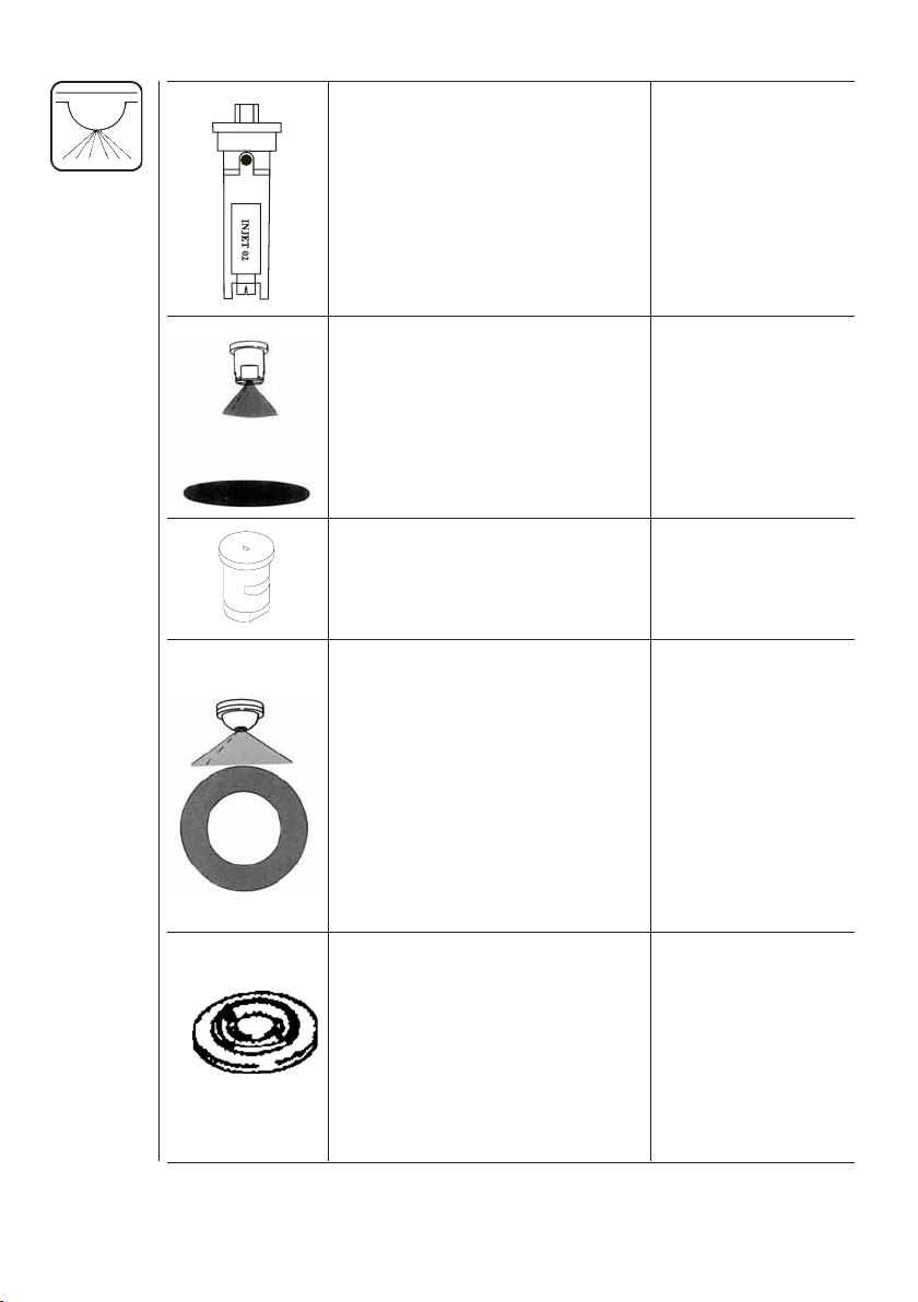
HARDI® INJET™ NOZZLES; air
inclusion nozzles with removable
restrictor. Color coded for fl ow
rate selection. In-Line Filters will
normally be used.
FLAT SPRAY NOZZLES in
65 degree, 80 degree, and
110 degree spray angles. For
herbicides, insecticides, and
fertilizer applications. 50, 80,
and 100 mesh screens are
normally used.
FLOOD NOZZLES set at 40°
spacing. Designed for high
vol ume application.
HOLLOW CONE NOZZLES
for high pressure and high
vol ume insecticide application
in row crops. 1553 nozzles are
ALWAYS used with swirl plates
shown below EXCEPT when
used as solid stream nozzles.
50, 80, or 100 mesh screens
are normally used with these
nozzles
SWIRL PLATE used in con junction with cone nozzle to create
desired spray pattern. These
swirls work with 1553 series
cone nozzles. Grey, blue, or black
swirls are used to create hollow
cone effect. White swirls are used
to create full cone effect.
4665-65 degree
2080-80 degree
4110-110 degree
Part # 330013-
O-ring
4598
1553
Must add swirl
to produce
hollow cone
pattern
Grey
Blue
Black
White
36 HARDI® NAVIGATOR 550M, 800M, 1000M CENTRIFUGAL OPERATOR'S MANUAL
Page 39

HOLLOW CONE CERAMIC
NOZZLES for high pressure
and high volume fungicide and
insecticide application.
LARGE DROPLET HOLLOW
CONE NOZZLE for use where
drift must be kept to a minimum.
These nozzles must always be
fi tted with 1553 nozzles and grey
swirl plates. 50, 80 or 100 mesh
screens are normally used with
these nozzles.
LARGE DROPLET FLAT
SPRAY TIP IN 150 DEGREE
SPRAY ANGLE. Always used in
conjunction with 1553-14-16-18
or 20 cone nozzle. 50, 80 or 100
mesh screens are normally used
with these nozzles.
SOLID STREAM NOZZLE
for high volume liquid fertilizer
application. In this application,
the 1553 nozzle is always used
with 330013 o-ring and 50, 80 or
100 mesh screens.
HARDI® QUINTASTREAM
5 HOLE LIQUID FERTILIZER
NOZZLE Five streams of liquid
are distributed at different angles
and fl ows. Highest fl ow is from the
middle stream and lowest in the
outer; overlapping streams. This
allows for boom movements that
do not influence distribution.
Boom heights of 20" can be used
as safely as 30".
1299
371077
371551
1553 less swirl
372011
thru
372019
37HARDI® NAVIGATOR 550M, 800M, 1000M CENTRIFUGAL OPERATOR'S MANUAL
Page 40

4.15 Calibration
WARNING:
WATER ONLY! IN ADDITION, WEAR PROTECTIVE
CLOTHING WHEN CALIBRATING YOUR SPRAYER!
Why must you calibrate a sprayer?
A nozzle selection chart will tell you what application rate you should
expect. Variations due to nozzle wear, errors in pressure adjustment, and
tractor speedometer can result in a possible error in application rate.
How do you calibrate a sprayer?
Calibration kits are available from HARDI®, #818493 for US gallons &
#818492 for metric calibration.
Following are some tips to remember when using the calibration kit
method:
• When determining the length of time required to drive the recommended
distance, drive in actual fi eld conditions with a half-full tank.
• Repeat the test several times, each time avoiding the tracks from the
previous test. Take the average of the times recorded.
• Calibration of the sprayer should be completed at the beginning of the
season and repeated after every 2 to 3 full days of spraying, and every
time you change volume rate or use new nozzles.
ALWAYS CALIBRATE YOUR SPRAYER WITH CLEAN
• Before you calibrate, check the fl ow of each nozzle. If it puts out more
than 10% of its original volume, replace it.
Select your calibration method: Ounce method or Formula method.
Then follow the steps described in the corresponding section(s):
38 HARDI® NAVIGATOR 550M, 800M, 1000M CENTRIFUGAL OPERATOR'S MANUAL
Page 41

Ounce Method
1. Determine how long it takes to cover the test strip. Use the following
chart to determine the length of your test strip. Row width for broadcast
application is equal to your nozzle spacing. For your drop nozzle or
band application, use row spacing.
Row width or nozzle spacing (in.) Distance (ft.)
40 102
38 107
36 113
34 120
32 127
30 136
28 146
26 157
24 170
22 185
20 204
18 227
16 255
14 291
2. Measure the amount of time it takes you to travel the test strip when
throttle is set at spraying speed.
3. In a container (with oz. measurements), catch the spray from one nozzle
for that amount of time. For drop or band nozzles, catch the spray from
all nozzles for the row.
4. Read the ounces in the container. That is the actual U.S. GPA applied.
(ounces = GPA)
39HARDI® NAVIGATOR 550M, 800M, 1000M CENTRIFUGAL OPERATOR'S MANUAL
Page 42

Formula Method
1. Check your spraying speed. Measure a test strip of at least 200 feet
(300 feet is ideal). Travel the distance at the speed you plan on spraying
and record the time it takes to travel the distance. Read from the chart
or use the formula to fi nd your exact travel speed.
Travel Time (in seconds)
Speed in MPH 200 ft. 300 ft.
3.0 45 68
3.5 39 58
4.0 34 51
Formula: 4.5 30 45
distance (ft.) x 0.68
seconds 6.0 23 34
7.0 19 29
7.5 18 27
8.0 17 26
9.0 15 23
= MPH
5.0 27 41
2. Calculate the required nozzle output. Use either the nozzle wheel (if
nozzle spacing is 20 inches), or this formula:
Formula: Formula:
GPA x MPH x W (in.)
GPM =
5940 5940
GPM =
10 x 7 x 20
= .24 GPM
Note: W= • Nozzle spacing (in inches) for broadcast application.
• Row spacing (in inches) divided by number of nozzles
per row for drop nozzle application.
• Sprayed band width or swath width (in inches) for band
application divided by number of nozzles per band.
• Note that on the nozzle wheel, W = 20 inches.
3. Set correct pressure. Read the required pressure from the nozzle table
in the nozzle catalogue or nozzle wheel. With clean water in the tank
and line, turn on the sprayer and set the target pressure. Collect the
spray from one nozzle for one minute in a container. Adjust pressure
until you collect the precise GPM called for.
40 HARDI® NAVIGATOR 550M, 800M, 1000M CENTRIFUGAL OPERATOR'S MANUAL
Page 43

Calibration For Carriers Other Than Water
Use the following water rate conversion chart to determine the right
conversion factor. When you've determined the new converted GPM or
GPA, you can follow the steps on either the pressure or ounce method
of calibration.
Weight of solution Specifi c Gravity Conversion Factors
7.00 lbs/gal .84 .92
8.00 lbs/gal .96 .98
8.34 lbs/gal-water 1.00 1.00
9.00 lbs/gal 1.08 1.04
10.00 lbs/gal 1.20 1.10
10.65 lbs/gal-28% N 1.28 1.13
11.00 lbs/gal 1.32 1.15
12.00 lbs/gal 1.44 1.20
14.00 lbs/gal 1.68 1.30
Example: 20 GPA of 28% N
Then GPA (solution) x conversion factor = GPA (water)
20 GPA (28% N) x 1.13 = 22.6 GPA (water)
Calibrate for 22.6 GPA of water
For conversion to Imperial gallons per acre, multiply U.S. GPA by .833
For conversion to liters per hectare, multiply U.S. GPA by 9.34
For conversion to liters per acre, multiply U.S. GPA by 3.78
Formula for tractor speed: Distance (in feet) x .682
= MPH
Second
41HARDI® NAVIGATOR 550M, 800M, 1000M CENTRIFUGAL OPERATOR'S MANUAL
Page 44

5.0 MAINTENANCE
IMPORTANT:
or
before servicing is done to avoid unnecessary contact with
chem icals.
In order to derive full benefi t from the sprayer for many years, the following
service and maintenance program should be followed.
5.1 Cleaning The Sprayer
Guidelines
Read the whole chemical label. Take note of any particular instructions
regarding recommended protective clothing, deactivating agents, etc. Read
the detergent and deactivating agent labels. If cleaning procedures are
given, follow them closely.
Be familiar with local legislation regarding disposal of pesticides washings,
mandatory decontamination methods, etc. Contact the appropriate
department, e.g. Dept. of Agriculture.
Pesticide washings can usually be sprayed out on a soakaway. This is an
area of ground that is not used for cropping. You must avoid seepage or
runoff of residue into streams, water courses, ditches, wells, springs, etc.
The washings from the cleaning area must not enter sewers. Drainage
must lead to an approved soakaway.
Always clean the boom at the end of your workday
Cleaning starts with the calibration, as a well calibrated sprayer will ensure
the minimal amount of remaining spray liquid.
It is good practice to clean the sprayer immediately after use, thereby
rendering the sprayer safe and ready for the next pesticide application.
This also prolongs the life of the components.
It is sometimes necessary to leave spray liquid in the tank for shor t periods,
e.g. overnight, or until the weather becomes suitable for spraying again.
Unauthorized persons and animals must not have access to the sprayer
under these circumstances.
If the product applied is corrosive, it is recommended to coat all metal
parts of the sprayer before and after use with a suitable rust inhibitor.
Remember: Clean sprayers are safe sprayers.
Clean sprayers are ready for action.
Clean sprayers can not be damaged by pesticides and their
solvents.
42 HARDI® NAVIGATOR 550M, 800M, 1000M CENTRIFUGAL OPERATOR'S MANUAL
Page 45

Cleaning the tank
1. Dilute remaining spray liquid in the tank with at least 10 parts of
water and spray the liquid out in the fi eld you have just sprayed.
Note: It is advisable to increase the forward speed (double if
possible) and reduce the pressure. For ISO F110 nozzles,
pressure may be reduced to 22psi (1.5 bar).
2. Select and use the appropriate protective clothing. Select detergent
suitable for cleaning and suitable deactivating agents if necessary.
3. Rinse and clean sprayer and tractor externally. Use detergent if
necessary.
4. Remove and clean tank fi lters and suction fi lters. Be careful not to
damage the mesh. Replace suction fi lter lid. Replace fi lters when the
sprayer is completely clean.
5. With the pump running, rinse the inside of the tank. Remember the
tank roof. Rinse and operate all components and any equipment that
has been in contact with the chemical.
6. After spraying the liquid out again in the fi eld, stop the pump and fi ll
at least 1/5 of the tank with clean water. Note that some chemicals
require the tank to be completely fi lled. Add appropriate detergent
and/or deactivating agent, eg. Washing soda or Triple ammonia.
Note: If a cleaning procedure is given on the chemical label, follow it
closely.
7. Start the pump and operate all controls enabling the liquid to come
in contact with all the components. Leave the distribution valves until
last. Some detergents and deactivating agents work best if left in the
tank for a short period. Check the label.
8. Drain the tank and let pump run dry, only for a few seconds. Rinse
inside of tank, again letting the pump run dry again only for a few
seconds.
Note: Do not run pump dry for longer than 3 seconds. Otherwise
severe damage to the pump will occur.
9. Stop the pump. If the chemicals used have a tendency to block
nozzles and fi lters, remove and clean them now.
10.Replace all the fi lters and nozzles and store the sprayer. If, from
previous experiences, it is noted that the solvents in the chemicals
are particularly aggressive, store the sprayer with the tank lid open.
Note: If the sprayer is cleaned with a high pressure cleaner we
recommend lubrication of the entire machine.
43HARDI® NAVIGATOR 550M, 800M, 1000M CENTRIFUGAL OPERATOR'S MANUAL
Page 46

5.2 Filters
IMPORTANT:
components that have been in contact with spray liquid.
Clean fi lters ensure :
• Sprayer components such as valves, diaphr agms and operat ing unit are
not hindered or damaged during operation.
• Nozzle blockages do not occur while spray ing.
• Long life of pump. A blocked suction filter will result in pump
cavit ation.
Wear protective clothing when servicing & handling
ISO Nozzle
Size
Pink (075)
Orange (01)
Green (015)
Yellow (02)
Lilac (025)
Blue (03)
Red (04)
& Larger
* Standard mesh
Suction Filter
(optional)
50 100 100 100
50 80 80 80
30* 50* 50* 50*
Inline Filters
(optional)
Nozzle
Screen
Pressure
Filter
44 HARDI® NAVIGATOR 550M, 800M, 1000M CENTRIFUGAL OPERATOR'S MANUAL
Page 47

5.3 Recommended Tire Pressure
The tires should not run under-infl ated. This only promotes instability
and rapid wear.
NAVIGATOR 550M
Tire size: Maximum pressure:
11L x 15" 36 psi (2.5 bar)
11.2 x 38" 24 psi (1.6 bar)
12.4 x 24" 24 psi (1.6 bar)
NAVIGATOR 800M/1000M
Tire size: Maximum pressure:
12.5L x 15" 36 psi (2.5 bar) - (TA no longer available)
13.6 x 38" 29 psi (2.0 bar)
12.4 x 42“ 10 ply 36 psi (2.5 bar)
The pressure is specifi ed for a fully loaded trailer. When traveling on hard
road surfaces with a maximum load, do not exceed 15 mph. Remember
it is easier to let off a little pressure for a specifi c use than to re-infl ate a
tire in mid-fi eld.
5.4 Wheel Nuts And Bearings Adjustment
WARNING:
Check wheel bolt tension after the fi rst 8 working hours, hereafter every
50 hours. Torque wheel nuts to 85 ft. lbs. maximum.
Check bearing for slack after the fi rst 8 hours of operation and again after
50 hours of operation. Thereafter every 100 hours. (Fig. 21)
BLOCK WHEELS ON TRAILER TO PREVENT ROLLING.
If necessary, adjust as follows:
1. Jack sprayer up. It is best to remove the wheel. (Make sure to
adequately support the sprayer and completely drain tank.)
2. Remove hub cap and cotter pin.
3. Axle nut is tightened until slight rotation resistance of hub is noted.
4. Now loosen axle nut until fi rst split pin hole is visible.
5. Insert cotter pin, fold and replace hub cap.
After 1000 hours or once a year, the axle
bear ings should be repacked with new
grease.
Fig. 21
45HARDI® NAVIGATOR 550M, 800M, 1000M CENTRIFUGAL OPERATOR'S MANUAL
Page 48

5.5 Tandem Axles
Fig. 22
*Check all shocks and all bearings every 1000 hours and replace if
needed.
Note: Tandem axles are only available on Navigator 550M.
46 HARDI® NAVIGATOR 550M, 800M, 1000M CENTRIFUGAL OPERATOR'S MANUAL
Page 49
5.6 Nozzle Tubes And Fittings
Poor seals are usually caused by;
• Missing O-rings or gaskets
• Damaged or incorrectly seated O-rings
• Dry or deformed O-rings or gaskets
• Foreign materials
Therefore, in case of leaks; DO NOT overtighten (Fig. 23). Disassemble,
check condition and position of O-ring or gasket, clean, lubricate and
reassemble.
For radial type seals (O-ring)(Fig.23) hand tighten only, do not use pli-
ers.
The O-rings need to be lubricated ALL THE WAY AROUND before fi tting
on to the nozzle tube.
Fig. 23
HARDI® recommends using a vegetable based oil to prolong the life of
the O-ring.
47HARDI® NAVIGATOR 550M, 800M, 1000M CENTRIFUGAL OPERATOR'S MANUAL
Page 50
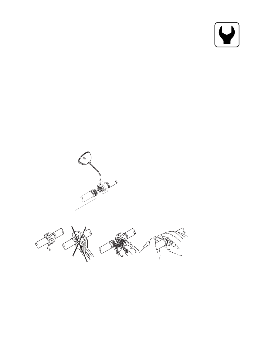
5.7 Checking The Valve Cone In Distribution Valves
Periodically check the distribution valves for proper sealing. This is done
while operating the sprayer with clean water.
1. Flush the sprayer with clean water and open all of
the distribution valves.
2. Cautiously remove clip (A) (Fig. 24) and remove
hose (B) (Fig. 24) for the constant pressure
device. When the housing is drained, bring
the sprayer up to operating pressure. If fl uid
continues to leak from the housing, the valve
cone (E) (Fig. 24) must be changed.
3. Shut the sprayer off and remove clip (C) (Fig. 24).
Pull the electrical motor off the valve housing.
4. Remove screw (D) (Fig. 24) and replace
the valve cone (E) (Fig. 24). Reassemble
in reverse order. Secure screw (D) (Fig. 24)
with Loctite.
Fig. 24
5.8 Hydraulic Driven Pump Repair Parts
204, 210, 310 (VALOX STD.) - 10527403
204, 210, 310 (CAST IRON) - 10527503
206-150 (CAST IRON) - 28022803
206-150 (VALOX STD.) - 28022703
304 (CAST IRON) - 28027203
304 (VALOX STD.) - 28027303
10527603
10527703
28027103 - 204, 210, 304, 310
10595903 - 206-150
10527903
10527903
MOTOR REPAIR KIT
204, 206-150, 210 - 10320003
304, 310 - 10320103
Fig. 25
Note: Any parts needed that are not shown, are available at your
local ACE pump supplier.
48 HARDI® NAVIGATOR 550M, 800M, 1000M CENTRIFUGAL OPERATOR'S MANUAL
Page 51
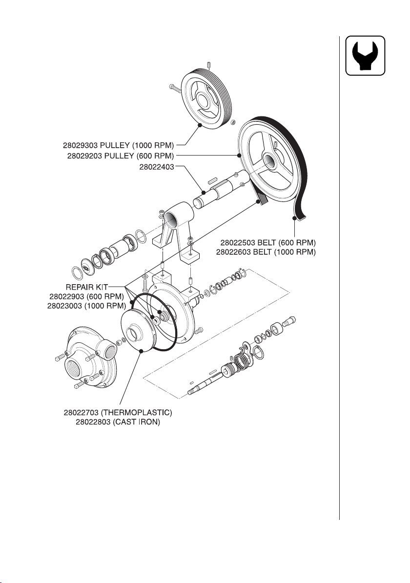
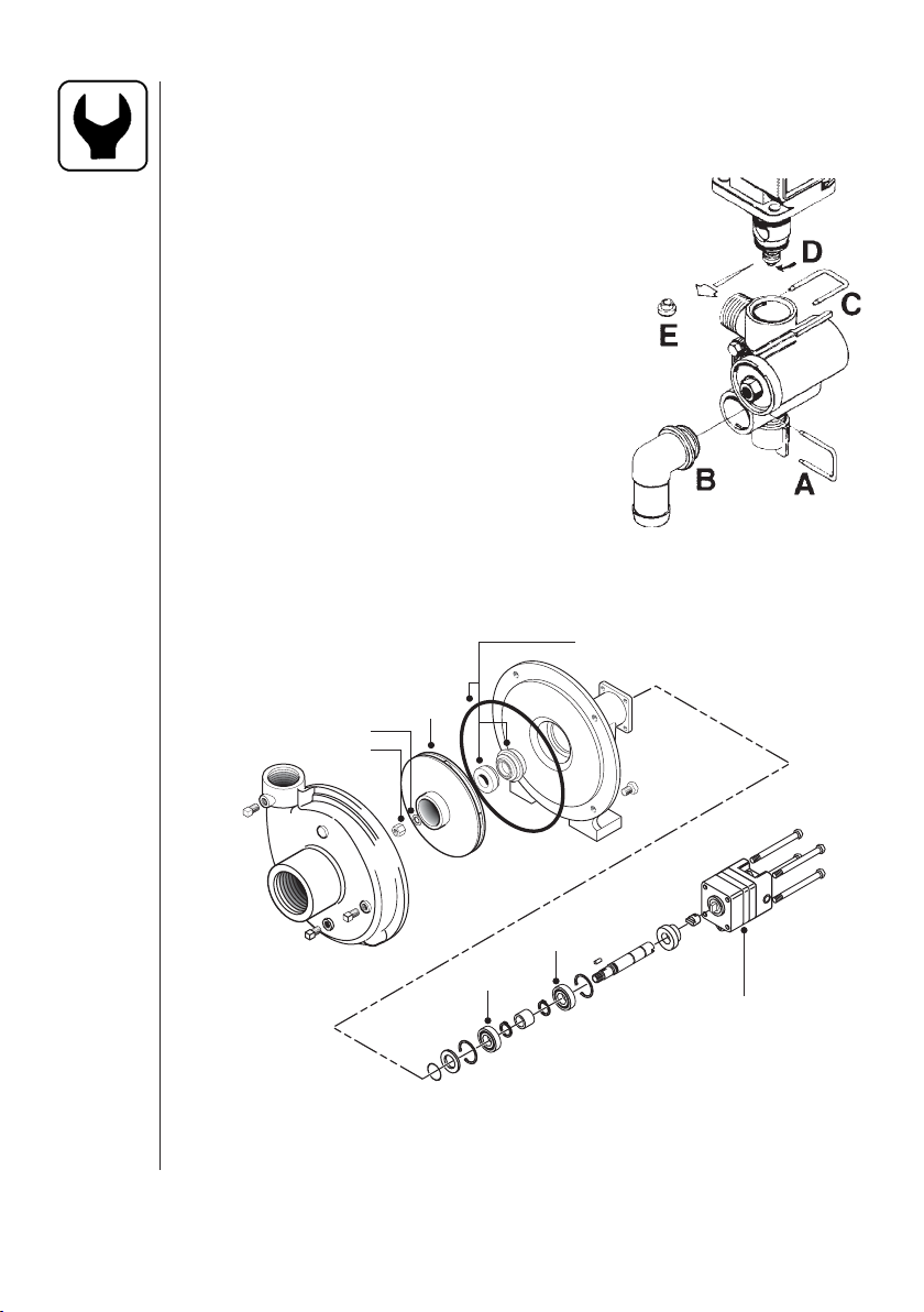
5.9 P.T.O. Belt Driven Pump Repair Parts
Fig. 26
Note: Any parts needed that are not shown, are available at your
local ACE pump supplier.
49HARDI® NAVIGATOR 550M, 800M, 1000M CENTRIFUGAL OPERATOR'S MANUAL
Page 52
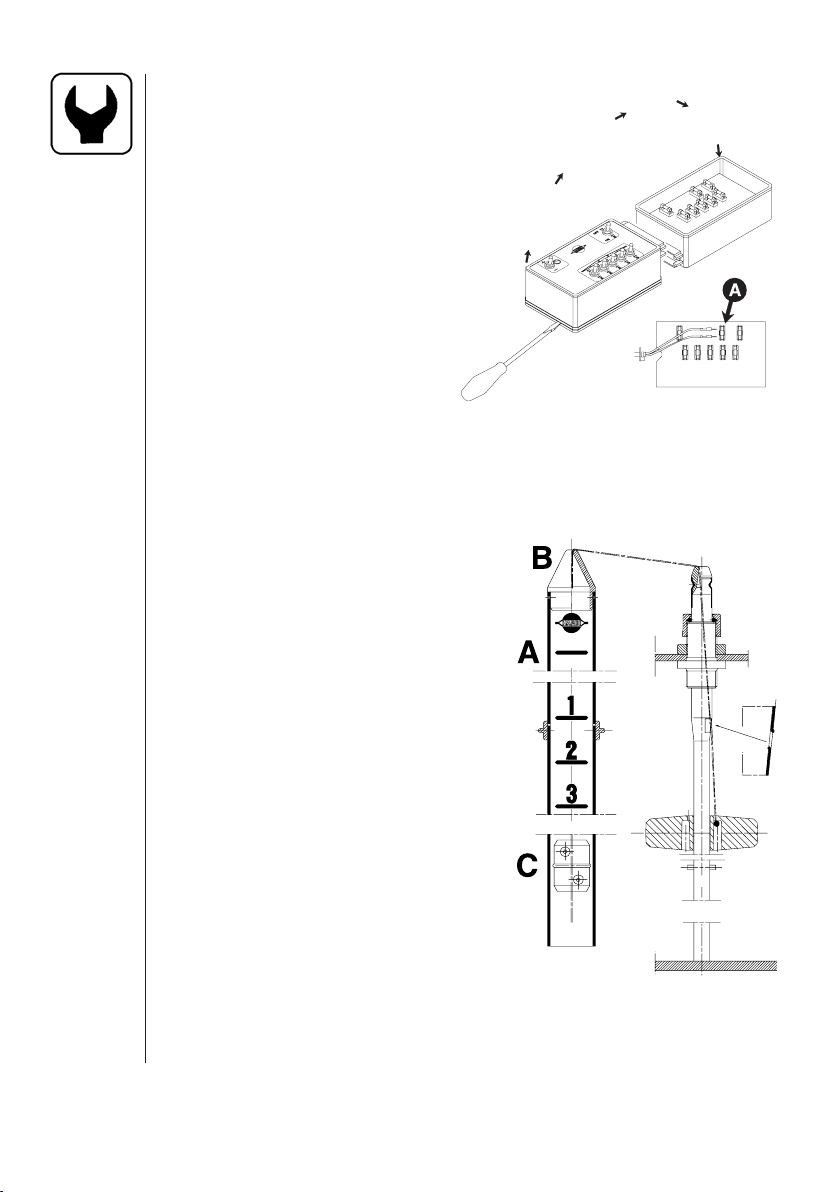
5.10 Emergency Operation Of ESC Controls
In case of power failure, it is possible to operate
all functions of the operating unit manually.
First disconnect the multiplug from the
control box. Now manually turn the
emergency control knobs.
The problem may be due to a blown
fuse. The fuses are placed in the control
box and are marked according to
functions.
Fuse type:
0.5 Amp (HARDI®#261125)
1.25 Amp (HARDI®#261589)
6.3 Amp (HARDI®#261090)
Fig. 27
5.11 Level Indicator
The level indicator should be checked
regularly. When the tank is empty, the
fl oater should rest on the stop pin on
the rod and the O-ring at the indicator
should be positioned at the top position
line (A) (Fig. 28).
If any deviation is found, pull out the plug
(B) (Fig. 28), loosen the screws (C) (Fig.
28) and adjust the length of the cord.
Note: The level indicator is not meant to
be an accurate indication of the specifi c
volume of your tank. Variations due to the
adjustment of the indicator, po sitioning of
the sprayer and the production of the tank
itself, are all factors leading to some inaccuracy. For precise mea surement rely
only on weight of the liquid or precise
fl owmeters when fi lling the tank.
50 HARDI® NAVIGATOR 550M, 800M, 1000M CENTRIFUGAL OPERATOR'S MANUAL
Fig. 28
Page 53
5.12 Lubrication
Recommended lubrication is shown in following tables.
Use ball bearing grease (lithium grease No. 2)
Note: If the sprayer is cleaned with a high pressure cleaner or fertilizer
has been used, we recommend lubrication of all sections. See
Eagle™ manual for boom greasing.
POS.
Position on
sprayer
Oil
2
Fig. 29
Grease
Operation
hours
1
3
4
6
Navigator 550M Centrifugal (Shown)
Page to fi nd more
information
Winter protection
or off-season
storage
5
1. Pump
2. P.T.O. (P.T.O. driven pumps only)
3. Idler arm (Belt driven pumps only)
4. Hitch Jack
5. Wheel Bearings
6. Tandem Axle (optional/not shown)
51HARDI® NAVIGATOR 550M, 800M, 1000M CENTRIFUGAL OPERATOR'S MANUAL
Page 54
POS.
1X 50
2
9016/18 pumps only
A
B
3
52 HARDI® NAVIGATOR 550M, 800M, 1000M CENTRIFUGAL OPERATOR'S MANUAL
X
X
X
10
50
40
16
16
Page 55

POS.
4X50
5 1000X 45
650X46
53HARDI® NAVIGATOR 550M, 800M, 1000M CENTRIFUGAL OPERATOR'S MANUAL
Page 56

6.0 OFF-SEASON STORAGE
When the spraying season is over, you should de vote some extra time
to the Spray er. If chem ical res idues are left over in the spray er for long
periods, it can reduce the life of the individual com ponents. To pre serve
the sprayer and pro tect the com ponents, carry out the following offseason stor age pro gram:
1. Clean the sprayer completely - inside and outside - as described
under "Cleaning The Spray er" (Section 5.1). Make sure that all
valves, hos es and auxiliary equipment have been cleaned with
detergent and fl ushed with clean wa ter afterwards, so no chem ical
residues are left in the sprayer.
2. Re place any damaged seals and repair any Ieaks.
3. Empty the sprayer com pletely and let the pump run dry, only for a
few seconds. Operate all valves and handles to drain as much water
out of the spraying circuit as pos sible. Let the pump run until air is
coming out of all nozzles. Re member to drain the fl ush tank also.
Note: Do not run pump dry for longer than 3 seconds. Otherwise
severe damage to the pump will occur.
4. Pour appr. 13 gal. (50 liters) antifreeze mixture con sisting of 1/3
automotive antifreeze and 2/3 water into the tank.
5. En gage the pump and op er ate all valves and func tions on the
MANIFOLD system, ESC unit, CHEM FILLER etc. al low ing the
antifreeze mix ture to be distributed around the en tire circuit. Open
the ESC main on/off switch and distribution valves so the an tifreeze
is sprayed through the nozzles as well. The an tifreeze will also
pre vent O-rings, seals, di aphragms etc. from dry ing out.
6. When the sprayer is dry, re move rust from any scratch es or
damages in the paint and touch up the paint.
7. Lubricate all lubricating points according to the lu bri cating scheme
regardless of intervals stated.
8. Re move the glycerine-fi lled pres sure gaug es and store them in a
vertical position in frost free con ditions.
9. Apply a thin layer of an ticorrosive oil (e.g. SHELL ENSIS FLU ID,
CASTROL RUSTILLO or sim ilar) on all metal parts. Avoid oil on
rubber parts, hoses and tires.
10. Fold the boom in transport po sition and re lieve pres sure from all
hydraulic func tions.
54 HARDI® NAVIGATOR 550M, 800M, 1000M CENTRIFUGAL OPERATOR'S MANUAL
Page 57

Off-Season Storage (continued)
11. AII elec tric plugs and sockets are to be stored in a dry plastic bag
to protect them against moisture, dirt, and cor rosion.
12. Remove all the control boxes (including any rate controller/monitor
control box and display) from the tractor and store them in a dry
and clean con dition.
13. Wipe hydraulic snap-couplers clean and fi t the dust caps.
14. Apply grease on all hydraulic ram pis ton rods which are not fully
retracted in the barrel to pro tect against corrosion.
15. Jack up the axle and place wooden blocks under the wheels, to
pre vent mois ture dam age and de for mation of the tires. Tire black
can be ap plied to the tire side walls to pre serve the rub ber.
16. To pro tect against dust, the spray er can be cov ered by a tar paulin.
Ensure ventilation to prevent condensation
6.1 Preparation After Off-Season Storage
After a stor age period the sprayer should be pre pared for the next
season the fol low ing way:
1. Remove the cover. (If fi tted)
2. Remove the blocks from under the wheels and ad just the tire pres-
sure.
3. Wipe off the grease from hy drau lic ram piston rods.
4. Fit the pressure gauges again. Seal with Tefl on tape.
5. Con nect the sprayer to the trac tor, in cluding hy drau lics and elec trics.
6. Check all hydraulic and elec tric func tions.
7. Emp ty the tank of remaining an tifreeze.
8. Rinse the entire liquid circuit on the spray er with clean water.
9. Fill with clean water and check all functions.
55HARDI® NAVIGATOR 550M, 800M, 1000M CENTRIFUGAL OPERATOR'S MANUAL
Page 58

7.0 ACCESSORIES
7.1 Clean Water Dispenser
Fig. 30
Clean Water Dispenser & Mounting Bracket (Eagle™ boom shown)
A handy source of fresh water on the sprayer to clean up plugged
nozzles and for rinsing gloves and hands after performing service or
maintenance.
7.2 Chemical Filler (optional)
Fig. 31
Chemical Filler Attachment Installed
Will inject all types of chemical formulations, liquid, powder or granules,
into the bottom of the tank near the agitation fl ow. A cleaning ring ensures
that chemical residue is removed from the fi ller tank.
56 HARDI® NAVIGATOR 550M, 800M, 1000M CENTRIFUGAL OPERATOR'S MANUAL
Page 59

7.3 Chemical Filler Bag & Bottle Rinse Kit (optional)
Fig. 32
Chemical-Filler Bag & Bottle Rinse Kit
A container rinse kit for liquid containers or plastic bags is also available
for installation into the chemical fi ller hopper.
7.4 Nurse Tank Quick Fill (optional)
Fig. 33
Nurse Tank Quick Fill
A quick attach hook-up for fi lling the sprayer tank from a nurse tank. Liquid
is fed into the bottom of the tank through a one-way valve providing a
better mix of water and chemical . The quick fi ll is equipped with a handy
1/4 turn shut-off valve.
57HARDI® NAVIGATOR 550M, 800M, 1000M CENTRIFUGAL OPERATOR'S MANUAL
Page 60

7.5 Foam Marker System (optional)
Fig. 34
Foam Marker Tank & Compressor
Fig. 35
Foam Marker Drop Assembly
The Foam Marker helps prevent skipping or over lapping during spray
application of spray solution, both which can be costly. HARDI® Foam
Marker features a trailer mounted compressor, poly tank, extruded foamer
hoses and in-cab electrical controls providing right or left drop selection
and the rate/quality of foam droplets. Refer to the Foam Marker Operator's
Manual for complete operation instructions.
58 HARDI® NAVIGATOR 550M, 800M, 1000M CENTRIFUGAL OPERATOR'S MANUAL
Page 61

7.6 4" Boom Pressure Gauge (optional)
Fig.38
Fig.36
4" Boom Pressure Gauge
A large and easy to read 4" boom pressure gauge to replace the standard
2-1/2" gauge. This gauge is to be mounted near the tractor cab allowing
the operator to monitor the boom pressure for more accurate control of
the application rate.
7.7 Flush System (optional)
Fig.37
Flush Tank (90 gal. shown)
Flush system provides a means to be able to fl ush the pump, controls,
boom feed lines and complete boom and nozzles with clean water from
a 90 gal. tank.
59HARDI® NAVIGATOR 550M, 800M, 1000M CENTRIFUGAL OPERATOR'S MANUAL
Page 62

7.8 Tank Rinse System (optional)
Fig. 38
Manifold Rinse Valve
Fig. 39
Rinse Nozzle on Top of Tank
The Rinse system can be added to the fl ush system which provides
a means to rinse the main tank using pressurized water to spray the
inside of the tank through specially designed spinning nozzles.
60 HARDI® NAVIGATOR 550M, 800M, 1000M CENTRIFUGAL OPERATOR'S MANUAL
Page 63

7.9 Spraygun And Hose Wrap (optional)
Fig. 40
Spraygun
A spraygun with adjustable spray pattern and 25 ft. of hose for spraying
fence row or spot spraying a small area can be installed onto your sprayer.
A handy hose wrap and spraygun holder can be conveniently located on
the sprayer to transport the spraygun.
7.10 HARDI® Monitor 1500 (optional)
Fig. 41
The HARDI® Monitor 1500 monitors the application rate. When used
with the electric control unit switch box, correct area covered and up to
8 spray boom section control is possible. Components can be added
for your individual requirements to control your operating unit, and
optional equipment.
61HARDI® NAVIGATOR 550M, 800M, 1000M CENTRIFUGAL OPERATOR'S MANUAL
Page 64

7.11 HARDI® Controller 2500 (optional)
Fig. 42
The HARDI® Controller 2500 permits automatic control of the application rate. This allows you to concentrate on driving as the rate is automatically maintained by the HC 2500. Press the "up" or "down" arrow
key to change the application rate. Easy, quick and simple. Up to 8
spray boom section control is possible.
7.12 Mustang 3500 Controller (optional)
The Mustang 3500 Controller offers fully integrated boom controls (3-7
sections), integrated foam marker controls, 3 possible preprogrammed
application rate settings, 9 different fi eld counters, DGPS compatible,
prepared for communication with Precision Farming Terminals and
pocket PC's (iPAQ - models: 3650, 3670), variable rate application, rain
& dust proof and 3 year warranty.
62 HARDI® NAVIGATOR 550M, 800M, 1000M CENTRIFUGAL OPERATOR'S MANUAL
Page 65

8.0 TROUBLESHOOTING
8.1 General Spray Systems
Problem Cause
1. No liquid getting to the pump. A. Suction side plugged.
B. Suction fi lter plugging (If fi tted).
2. Lack of pressure A. Suction side plugged.
B. Suction fi lter plugging (If fi tted).
C. Hydraulic motor shaft coupling
loose or fork pin missing.
D. Flow limiting valve closed
because of too much hydraulic
fl ow to the pump motor.
E. P.T.O. speed not fast enough
(P.T.O. driven pumps only).
F. Bad seat on spool valve for
boom section control.
G. Flush valve not in correct
position. (Units equipped with
Flush & Rinse™ system only).
H. Bad suction valve or suction
side air leak.
I. P.T.O. not engaged (P.T.O.
driven pumps only).
J. Belt broke or missing (Belt
Driven pumps only).
3. Pressure jumping A. Output from by-pass lines
causing a disturbance around
suction hose.
B. Small tear or pin hole in suction
hose.
C. Bad O-ring on suction fi lter
(if fi tted).
D. P.T.O. shaft slipping on pump
crank shaft (P.T.O. driven pumps
only).
E. Suction side air leak.
63HARDI® NAVIGATOR 550M, 800M, 1000M CENTRIFUGAL OPERATOR'S MANUAL
Page 66

4. Pressure dropping A. Output from by-pass lines
causing a disturbance around
suction tube.
B. Suction fi lter plugging (If fi tted).
C. P.T.O. shaft slipping on pump
crank shaft (P.T.O. driven
pumps only).
D. Bad seat on spool valve for
boom section control.
E. Bad suction valve or suction
side air leak.
5. Liquid leaking from pump A. Damaged pump seal.
6. Electric control unit not A. Fuse blown.
functioning B. ESC motor bad or micro-switch
plate loose.
C. Bad seat on spool valve.
D. Bad switch or plug on control
box.
E. Print board at back of control
corroded or damaged.
7. Less spray out of one boom A. Bad seat on spool valve for
section than others. boom section control.
8. Poor agitation A. Agitation valve not open.
B. Agitation nozzle plugged.
C. Agitation nozzle missing.
9. Excessive vibrations in hoses A. P.T.O. shaft slipping on pump
crank shaft (P.T.O. driven
pumps only).
B. Suction side air leak.
10. Can't get tank empty. A. Output from by-pass lines
causing a disturbance around
suction tube.
B. Crack or pin hole in suction
tube.
C. Tank is not level (change angle
of tongue).
64 HARDI® NAVIGATOR 550M, 800M, 1000M CENTRIFUGAL OPERATOR'S MANUAL
Page 67

11. Boom nozzle leaking. A. Seat on boom section shut-off
valve is worn or cracked.
B. Bad seat on spool valve.
C. Bad Non-Drip valve diaphragm.
8.2 Foam Marker
Problem Cause
1. Compressor will not run. A. Short in electrical system or
bad compressor.
B. 12 volt supply not connected
or bad connection.
C. Weak power supply.
D. Fuse blown.
E. Defective switch in control
box.
F. Bad printboard (Pre 2002).
2. Compressor runs but will A. Solenoid not working.
not make foam. B. Not enough foam concentrate.
C. Solenoid valve plugged.
D. Weak power supply.
E. Bad printboard (Pre 2002).
3. Will not make enough foam. A. Line leak or line pinched.
B. Solenoid valve plugged.
C. Weak foam concentrate
mixture.
D. Water too hard (add water
softener).
4. Foam drops will not last. A. Not enough foam concentrate.
B. Frequency valve not opened
enough (Pre 2002).
C. Weak foam concentrate.
D. Water too hard (Add water
softener).
65HARDI® NAVIGATOR 550M, 800M, 1000M CENTRIFUGAL OPERATOR'S MANUAL
Page 68

5. Keeps blowing fuses. A. Short in electrical system or
bad compressor.
B. Weak power supply.
C. Bad relay on printboard
(Pre 2002).
D. Tank fi lter plugged.
8.3 Flush & Rinse™
1. System will not fl ush (pump, A. Flush valve not in correct
control, and boom) position.
B. P.T.O. not engaged.
C. Flow limiting valve closed
because of too much hydraulic
fl ow to the pump motor.
2. System will fl ush but not A. Rinse valve not in correct
rinse. position.
3. Rinse nozzle has poor output. A. Bad fl ush valve or suction side
air leak.
B. Rinse valve not in correct
position.
D. Pressure too low or high (rinse
nozzle gauge).
8.4 Chemical Filler
1. Filler tank will not empty. A. Pressure selection valve not in
correct position.
B. Not enough fl ow from pump.
C. Sprayer pump not running.
2. Filler tank empties too slow. A. Bottom tank discharge valve
not open all the way.
B. Not enough fl ow from pump.
3. Filler tank backfi lls when A. Restrictor cone missing.
bottom tank discharge valve B. Restrictor cone on wrong side
is open. of the valve.
C. Not enough fl ow from pump.
66 HARDI® NAVIGATOR 550M, 800M, 1000M CENTRIFUGAL OPERATOR'S MANUAL
Page 69

9.0 WARRANTY POLICY AND CONDITIONS
HARDI® INC. , 1500 West 76th Street, Davenport, Iowa, USA; 8550 W. Roosevelt Avenue, Visalia, California,
USA and 290 Sovereign Road, London, Ontario, Canada hereinafter called "HARDI
warranty in accordance with the provisions below to each original retail purchaser of HARDI
its own manufacturer, from an authorized HARDI® dealer, that such equipment is at the time of delivery to such
purchaser, free from defects in material and workmanship and that such equipment will be warranted for a period
of one year from the date of delivery to the end user providing the machine is used and serviced in accordance
with the recommendations in the Operator's Manual and is operated under normal farm conditions.
1. This limited warranty is subject to the following exceptions:
a) Parts of the machine not manufactured by HARDI®, (i.e. engines, tires, tubes, electronic controls,
and other components or trade accessories, etc.) are not covered by this warranty but are subject
to the warranty of the original manufacturer. Any claim falling into this category will be taken up with
the manufacturer concerned.
b) This warranty will be withdrawn if any equipment has been used for purposes other than for which
it was intended or if it has been misused, neglected, or damaged by accident, let out on hire or
furnished by a rental agency. Nor can claims be accepted if parts other than those manufactured
by HARDI® have been incorporated in any of our equipment. Further, HARDI® shall not be responsible
for damage in transit or handling by any common carrier and under no circumstances within or
without the warranty period will HARDI® be liable for damages of loss of use, or damages resulting
from delay or any consequential damage.
2. We cannot be held responsible for loss of livestock, loss of crops, loss because of delays in harvesting or
any expense or loss incurred for labor, supplies, substitute machinery, rental for any other reason, or for
injuries either to the owner or to a third party, nor can we be called upon to be responsible for labor charges,
other than originally agreed, incurred in the removal or replacement of components.
3. The customer will be responsible for and bear the costs of:
a) Normal maintenance such as greasing, maintenance of oil levels, minor adjustments, etc.
b) Transportation of any HARDI® product to and from where the warranty work is performed.
c) Dealer travel time to and from the machine or to deliver and return the machine from the service
workshop for repair.
d) Dealer traveling costs.
4. Parts defi ned as normal wearing items, (i.e. tires and V-belts) are not in any way covered under this
warranty.
5. This warranty will not apply to any product which is altered or modifi ed without the express written
permission of HARDI® and/or repaired by anyone other than an Authorized Service Dealer.
6. Warranty is dependent upon the strict observance by the purchaser of the following provisions:
a) That this warranty may not be assigned or transferred to anyone.
b) That the Warranty Registration Certifi cate has been correctly completed by dealer and purchaser with
their names and addresses, dated, signed and returned to the appropriate address as given on the
Warranty Registration Certifi cate.
c) That all safety instructions in the operator's manual shall be followed and all safety guards regularly
inspected and replaced where necessary.
7. No warranty is given on second-hand products and none is to be implied.
®
", offers the following limited
®
new equipment of
67HARDI® NAVIGATOR 550M, 800M, 1000M CENTRIFUGAL OPERATOR'S MANUAL
Page 70

8. Subject to the following terms, conditions and contributions, HARDI® extends the warranty on polyethylene
tanks (excluding fi ttings, lids and gaskets) to FIVE YEARS. To qualify for this extended warranty, the tank must
be drained and fl ushed with fresh water after each day of use. HARDI®'s liability is limited to replacement of
the tank, FOB our plant at no cost to the purchaser during the fi rst twelve months; at 20% of the then current
price during the second year ; at 40% during the third year ; at 60% during the fourth year ; and at 80% during
the fi fth year. This fi ve year extended warranty is subject, in each instance, to the tank being inspected and
approved for replacement or repair by HARDI® personnel before HARDI® will accept any liability hereunder.
9. Subject to the following terms, conditions, contributions, HARDI® extends the warranty on HARDI® diaphragm
pumps (excluding wearing parts such as diaphragms, valves, etc.) to FIVE YEARS. To qualify for this extended
warranty, the pump must be drained and fl ushed with fresh water after each day of use. Hardi®'s liability is
limited to replacement of defective parts, FOB our plant at no cost to the purchaser during the fi rst twelve
months after date of purchase, at 20% of the then current retail price during the second year ; at 40% during
the third year ; at 60% during the fourth year ; and at 80% during the fi fth year. This fi ve year extended warranty
is subject, in each instance, to the pump being inspected and approved for replacement or repair by HARDI
personnel before HARDI® will accept any liability hereunder.
10. HARDI® reserves the right to incorporate any change in design in its products without obligation to make
such changes on units previously manufactured.
11. The judgement of HARDI® in all cases of claims under this warranty shall be fi nal and conclusive and the
purchaser agrees to accept its decisions on all questions as to defect and to the exchange of any part or
parts.
12. No employee or representative is authorized to change this warranty in any way or grant any other warranty
unless such change is made in writing and signed by an offi cer of HARDI® at it's head offi ce.
13. Any warranty work performed which will exceed $400.00 MUST be approved IN ADVANCE by the Service
Manager.
14. Any pump replacement must be approved in advance by the Service Manager.
15. Claims under this policy must be fi led with HARDI® within thirty (30) days of work performed or warranty
shall be void.
16. Parts requested must be returned prepaid within thirty (30) days for warranty settlement.
17. Warranty claims must be COMPLETELY fi lled out properly or will be returned.
DISCLAIMER OF FURTHER WARRANTY
THERE ARE NO WARRANTIES, EXPRESSED OR IMPLIED, EXCEPT AS SET FORTH ABOVE. THERE ARE
NO WARRANTIES WHICH EXTEND BEYOND THE DESCRIPTION OF THE PRODUCT CONTAINED HEREIN.
IN NO EVENT SHALL THE COMPANY BE LIABLE FOR INDIRECT, SPECIAL OR CONSEQUENTIAL DAMAGES
(SUCH AS LOSS OF ANTICIPATED PROFITS) IN CONNECTION WITH THE RETAIL PURCHASER'S USE
OF THE PRODUCT.
®
68 HARDI® NAVIGATOR 550M, 800M, 1000M CENTRIFUGAL OPERATOR'S MANUAL
Page 71

Page 72

For Product, Service or Warranty Information:
- Please contact your local HARDI® dealer.
To contact HARDI® directly:
- Please use the HARDI® Customer Service number: 1-866-770-7063
- Or send your email to: CUSTSERV@hardi-us.com
Visit us online at: www.hardi-us.com
HARDI® NORTH AMERICA INC.
1500 West 76th St.
Davenport, Iowa 52806
Phone: (563) 386-1730
Fax: (563) 386-1710
8550 W. Roosevelt Avenue
Visalia, California 93291
Phone: (559) 651-4016
Fax: (559) 651-4160
337 Sovereign Rd.
London, Ontario N6M 1A6
Phone: (519) 659-2771
Fax: (519) 659-2821
 Loading...