

Page 1
N-SERIES 3-PT SPRAYER
DIAPHRAGM
Operator's Manual
67302903 (08/10)
Page 2

Page 3

HARDI
N-SERIES 3-PT SPRAYER
DIAPHRAGM
Operator's Manual
67302903 (08/10)
HARDI® reserves the right to make changes in design,
material, or specifi cation without notice thereof.
HARDI® and other product names are registered trademarks
of HARDI® Inc. in the U.S. and in other countries.
Page 4

TABLE OF CONTENTS
1.0 INTRODUCTION . . . . . . . . . . . . . . . . . . . . . . . . . . . . . . . . . 6
2.0 SAFETY INFORMATION. . . . . . . . . . . . . . . . . . . . . . . . . . . 8
2.1 Follow Safety Instructions . . . . . . . . . . . . . . . . . . . . 9
2.2 Operating the Sprayer Safely . . . . . . . . . . . . . . . . . 9
2.3 Handling Chemical Products Safely . . . . . . . . . . . . 11
2.4 Local Poison Information Center. . . . . . . . . . . . . . . 12
3.0 HOOKING UP THE SPRAYER . . . . . . . . . . . . . . . . . . . . . . 13
3.1 P.T.O. Shaft Operator Safety . . . . . . . . . . . . . . . . . . 14
3.2 Installation Of P.T.O. Shaft. . . . . . . . . . . . . . . . . . . . 14
3.3 Power Supply (electric controls only) . . . . . . . . . . . 16
3.4 Control box (electric controls only) . . . . . . . . . . . . . 17
4.0 OPERATING INSTRUCTIONS . . . . . . . . . . . . . . . . . . . . . . 18
4.1 Filling The Main Tank (all models). . . . . . . . . . . . . . 18
4.2 Filling The Clean Water Tank (optional). . . . . . . . . . 18
4.3 EC-3 Standard Plumbing Diagram . . . . . . . . . . . . . 19
4.4 EC-3 Plumbing Diagram w/optional Rate Controller 20
4.5 Adjustment of the EC-3 Electric Controls . . . . . . . . 21
4.6 ET-3 Manual Control Plumbing Diagram. . . . . . . . . 23
4.7 Adjustment of the ET-3 Manual Controls. . . . . . . . . 24
4.8 ET-2 Manual Control Plumbing Diagram. . . . . . . . . 26
4.9 Adjustment of the ET-2 Manual Controls. . . . . . . . . 27
4.10 BK-3 Manual Control Plumbing Diagram . . . . . . . . 29
4.11 Adjustment of the BK-3 Manual Controls . . . . . . . . 30
4.12 Operation Of The Tank Drain Valve (all models) . . . 33
4.13 Adjustment of Air Pressure in Pressure Damper
(All models). . . . . . . . . . . . . . . . . . . . . . . . . . . . . . . 33
4.14 Self Cleaning Filter (optional) . . . . . . . . . . . . . . . . . 34
4.15 Unfolding/Folding Boom
(All models with standard booms). . . . . . . . . . . . . . 35
4.16 Boom Height Adjustment
(All models with standard booms). . . . . . . . . . . . . . 36
2 HARDI® N-SERIES 3-PT SPRAYER DIAPHRAGM OPERATOR'S MANUAL
Page 5

5.0 NOZZLE SELECTION . . . . . . . . . . . . . . . . . . . . . . . . . . . . . 37
5.1 Boom Nozzle Selection
(All models with standard booms). . . . . . . . . . . . . . 37
5.2 Giant End Nozzle Selection (Pasture Sprayer only) 40
5.3 Spraygun Nozzle Selection (All models). . . . . . . . . 42
5.4 Calibration (All models with standard booms). . . . . 43
5.5 Calibration (Pasture sprayer model only) . . . . . . . . 47
6.0 MAINTENANCE. . . . . . . . . . . . . . . . . . . . . . . . . . . . . . . . . . 51
6.1 Cleaning The Sprayer . . . . . . . . . . . . . . . . . . . . . . . 51
6.2 Filters . . . . . . . . . . . . . . . . . . . . . . . . . . . . . . . . . . . 53
6.3 Nozzles And Fittings . . . . . . . . . . . . . . . . . . . . . . . . 54
6.4 Replacement Of P.T.O. Shaft Protection Guards. . . 55
6.5 Replacement Of P.T.O. Shaft Cross Journals . . . . . 55
6.6 Changing the Valves and Diaphragms (all pumps). 56
6.7 Breakaway Clutch Adjustment (MB Boom only) . . . 57
6.8 Lubrication. . . . . . . . . . . . . . . . . . . . . . . . . . . . . . . . 58
7.0 OFF-SEASON STORAGE. . . . . . . . . . . . . . . . . . . . . . . . . . 61
7.1 Preparation after Off-Season Storage. . . . . . . . . . . 62
8.0 ACCESSORIES . . . . . . . . . . . . . . . . . . . . . . . . . . . . . . . . . . 63
8.1 Clean Water Dispenser (optional) . . . . . . . . . . . . . . 63
8.2 Spraygun And Hose wrap (optional). . . . . . . . . . . . 63
8.3 Maverick Rate Controller (optional). . . . . . . . . . . . . 64
8.4 Large 4" Pressure Gauge (optional) . . . . . . . . . . . . 64
8.5 Chemical Filler (optional) . . . . . . . . . . . . . . . . . . . . 65
8.6 Chemical Filler Bag & Bottle Rinse Kit (optional) . . 65
8.7 SMV Sign Kit (optional). . . . . . . . . . . . . . . . . . . . . . 66
9.0 TROUBLESHOOTING. . . . . . . . . . . . . . . . . . . . . . . . . . . . . 67
9.1 General Spray Systems . . . . . . . . . . . . . . . . . . . . . 67
10.0 TECHNICAL SPECIFICATIONS . . . . . . . . . . . . . . . . . . . . 69
10.1 Dimensions and weights. . . . . . . . . . . . . . . . . . . . . 69
10.2 Power consumption. . . . . . . . . . . . . . . . . . . . . . . . . 69
11.0 WARRANTY POLICY AND CONDITIONS . . . . . . . . . . . . 70
12.0 NOTES . . . . . . . . . . . . . . . . . . . . . . . . . . . . . . . . . . . . . . . . 72
3HARDI® N-SERIES 3-PT SPRAYER DIAPHRAGM OPERATOR'S MANUAL
Page 6

HARDI
Dear Owner,
Thank you for purchasing a HARDI
increasing family of HARDI® sprayer owners.
Our sprayers and accessories are rapidly becoming a familiar sight
on North American farms. We believe that this results from growers
becoming increasingly conscious of crop protection input costs and the
vital need for cost effective spray application equipment.
Please take the time to thoroughly read the Operator’s Manual before
using your equipment. You will fi nd many helpful hints as well as
important safety and operation information.
Some of the features on your HARDI® sprayer were suggested by
growers. There is no substitute for “on farm” experience and we invite
your comments and suggestions. If any portion of this instruction book
remains unclear after reading it, contact your HARDI® dealer or service
personnel for further explanation before using the equipment.
For Product, Service or Warranty Information:
- Please contact your local HARDI® dealer.
To contact HARDI® directly:
- Please use the HARDI® Customer Service number: 1-866-770-7063
- Or send your email to CUSTSERV@hardi-us.com
®
product and welcome to the ever-
Visit us online at: www.hardi-us.com
HARDI® NORTH AMERICA INC.
1500 West 76th St.
Davenport, Iowa 52806
Phone: (563) 386-1730
Fax: (563) 386-1710
Sincerely,
Dale M. Szuminski
President
4 HARDI® N-SERIES 3-PT SPRAYER DIAPHRAGM OPERATOR'S MANUAL
337 Sovereign Rd.
London, Ontario N6M 1A6
Phone: (519) 659-2771
Fax: (519) 659-2821
Page 7
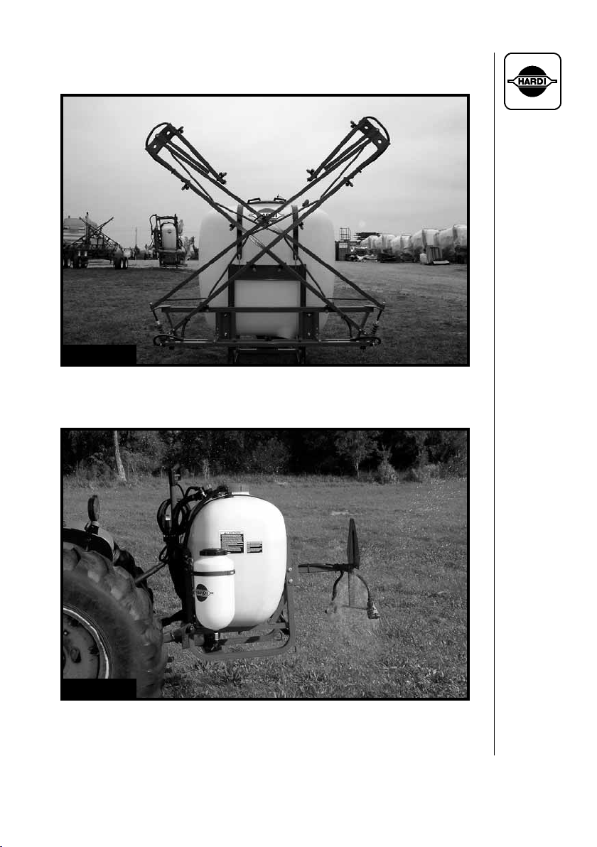
Fig. 1
N155 GALLON 3-PT WITH 26' MB BOOM
Fig. 2
N105 GALLON 3-PT PASTURE SPRAYER MODEL
5HARDI® N-SERIES 3-PT SPRAYER DIAPHRAGM OPERATOR'S MANUAL
Page 8

1.0 INTRODUCTION
We congratulate you for choosing a HARDI
®
plant protection product.
The reliability and effi ciency of this product depends on your care. The
fi rst step is to carefully read and pay attention to this operator's manual.
It contains essential information for the effi cient use and long life of this
quality product.
As this instruction book covers all N-series models, please pay
attention to the sections dealing with your specifi c model.
This manual covers the HARDI
®
N-series 3-PT sprayers, available in
105, 155 or 210 gallon (400 L, 600 L or 800 L) capacities. They are
equipped with a HARDI® 603, 1203 or 1303 diaphragm pump (540
RPM P.T.O. drive), 3-PT frame and tank with electrical (EC) or manual
(ET or BK) controls. Available standard booms include:
N105: 20' MB, 26' MB
N155: 20' MB, 26' MB, 33' MB, 40' MB
N210: 20' MB, 26' MB, 33' MB, 40' MB
Other boom options include: No boom (spray gun only), pasture
sprayer nozzles (30', 40', 50' spray width), VS8D 1-Row Berry Boom or
VII 2-Row Berry Boom.
The heart of your sprayer is the diaphragm pump. The design is simple,
resulting in low maintenance requirements and guaranteed pump life.
The bearings and crankshaft are grease lubricated and are therefore
protected from spray solution if any diaphragm fails in service. A drain
hole is located in the base of the crank case to facilitate the draining of
any foreign matter. The pump is self-priming and can be run dry without
damage.
The EC-3 electric control unit consists of: Electrically operated master
on/off valve, electrically operated boom distribution valves, manual
pressure adjustment valve, 2-1/2" pressure gauge, and adjustable
pressure agitation.
The ET-2/ET-3 manual control unit consists of: Manual pressure
adjustment valve, boom distribution valves, 2-1/2" pressure gauge, and
adjustable pressure agitation.
Note: ET-2 control is used on pasture sprayer model
6 HARDI® N-SERIES 3-PT SPRAYER DIAPHRAGM OPERATOR'S MANUAL
Page 9

The BK-3 manual control unit consists of: On/off function, distribution
valves with pressure equalization, manual pressure adjustment valve,
pressure fi lter with 2-1/2" pressure gauge and HARDI-MATIC. The
HARDI-MATIC is a mechanical rate controller that ensures a constant
volume of spray solution per acre at varying speeds in the same gear.
The tanks, made of impact proof and chemical resistant poly eth yl ene,
have a purposeful design with rounded contours and a large deep
sump to allow for ef fi cient cleaning and draining. The tanks are
equipped with a top suction fi lter for easy service and a top operated
tank drain.
All standard booms (20', 26', 33' or 40' MB) feature ISO fl at fan nozzles
with 20" spacing. The 40' MB boom features a self-levelling trapeze
center.
The pasture sprayer model includes a height adjustable offset nozzle
bracket bolted to the rear of the 3-PT frame for mounting either two
HARDI
®
Giant End Nozzles or two "Boom Buster" nozzles (Evergreen
Products, Inc.). The two HARDI® Giant End Nozzles provide a
consistent spray pattern and droplet distribution. They are available
in three different sizes ranging from 3.22 - 9.38 GPM (12.7 - 36 l/min)
between 20 - 70 PSI (1.5 - 5 bar) spray pressure. Under optimal
spraying conditions, the maximum spray swath covered by the two
opposite mounted HARDI® Giant End Nozzles is 30', 40' or 50' (10m,
12m or 16m).
Available options include:
Spray Mate II Rate Controller (requires electric EC control)
Remote control cable (for manual BK control only)
Self cleaning fi lter (with 50 mesh fi lter)
4 gallon (15 L) clean water dispenser
Chemical fi ller with optional bag & bottle rinse
4" pressure gauge
Hose wrap with 25' of 3/8" hose and a model 60L HARDI® spray gun
Hose reel with 160' of 3/8" hose and a model 60L HARDI® spray gun*
Hose reel with 275' of 5/8" hose and a model 60L HARDI® spray gun**
Hydraulic boom vertical fold (40' MB boom only)
SMV Sign kit
* Not available on N210 with boom
** Not available with boom
7HARDI® N-SERIES 3-PT SPRAYER DIAPHRAGM OPERATOR'S MANUAL
Page 10

2.0 SAFETY INFORMATION
WARNING
ALWAYS READ OPERATOR'S MANUAL BEFORE
USING EQUIPMENT
DO NOT REMOVE ANY SAFETY DEVICES OR
SHIELDS. NEVER SERVICE, CLEAN OR REPAIR A
MACHINE WHILE IT IS OPERATING
WARNING
ALWAYS WATCH FOR THIS SYMBOL TO POINT OUT
IMPORTANT SAFETY PRECAUTIONS
IT MEANS ATTENTION! BECOME ALERT!
YOUR SAFETY IS INVOLVED!
8 HARDI® N-SERIES 3-PT SPRAYER DIAPHRAGM OPERATOR'S MANUAL
Page 11

RECOGNIZE SAFETY INFORMATION
This is the Safety-alert symbol. When you see
this symbol on your machine or in this manual,
be alert to the potential for per son al injury.
Follow recommended precautions and safe
operating practices.
2.1 Follow Safety Instructions
- Carefully read all the safety messages in this manual and the safety
labels fi tted to the machine. Keep safety labels in good condition.
Replace missing or damaged safety labels. Be sure that new equipment components include any current safety labels. Replacement
safety labels are available from your authorized HARDI® dealer.
- Learn how to operate the sprayer and how to use the controls
prop erly. Do not let anyone operate the machine without proper
instructions.
- Keep your sprayer in proper working condition. Unauthorized modi-
fi cations or use may impair the function and/or safety and affect the
machine's life.
- If you do not understand any part of this manual and need assis-
tance, please contact your authorized HARDI® dealer.
2.2 Operating The Sprayer Safely
1. Read the complete manual carefully and become familiar with the
operation of the equipment before initial operation in each spraying
season. Failure to do so may result in possible over or under-application of spray solution which may drastically affect crop production
and lead to personal injury.
2. Before starting the engine on the tractor unit, be sure all operating
controls are in the off or neutral position (including spray controls)
and disengage the tractor power train.
3. Operate spray functions only when seated in the operator’s seat.
4. One of the most frequent causes of personal injury or death results
from persons falling off or being run over. Do not permit others to
ride on or in. Only one person, the operator, should be on the machine when in operation.
9HARDI® N-SERIES 3-PT SPRAYER DIAPHRAGM OPERATOR'S MANUAL
Page 12

5. Before leaving the tractor seat, stop the engine, put all controls in
neutral, and put the transmission control lever in the park position or
neutral with the brakes locked. Read the tractor operations manual
for added safety precautions.
6. P.T.O. driven equipment can cause serious injury. Before working
on or near the P.T.O. shaft, servicing or cleaning the equipment, put
P.T.O. lever in the DISENGAGE position and stop the engine.
7. Keep hands, feet & clothing away from moving parts.
8. Wear relatively tight and belted clothing to prevent from being caught
on some part of the machine.
9. Slow down when turning.
10. Always keep children away from your sprayer and/or tractor unit.
11. Slow moving tractors and spray equipment can create a hazard
when on public roads. Avoid personal injury or death resulting
from any accidents by using fl ashing lights. Local regulations may
require installation of fl ashing warning lights.
12. Understand service procedures before undertaking any mainte-
nance. Never lubricate, service, or adjust the machine while it's
moving. Securely support any components before working on
them.
13. Keep all parts in good condition and properly installed. Fix dam-
aged parts immediately. Replace worn or broken parts. Remove
excessive buildup of grease, oil or debris.
10 HARDI® N-SERIES 3-PT SPRAYER DIAPHRAGM OPERATOR'S MANUAL
Page 13

2.3 Handling Chemical Products Safely
1. Direct exposure to hazardous chemicals can cause serious injury.
These chemicals can include lubricants, coolants, paints, adhesives
and agricultural chemicals. Material Safety Data Sheets (M.S.D.S.)
are available for all hazardous chemicals which inform the user of
specifi c details including, physical and health hazards, safety procedures, and emergency response techniques.
2. Protective clothing such as rubber gloves, goggles, coveralls and
respirator must be worn while handling chemicals. All protective
clothing should be kept in excellent condition and cleaned regularly
or discarded.
3. If chemicals come in contact with any exposed skin areas, wash immediately with clean water and detergent. Never place nozzle tips or
any other components that have been exposed to chemicals to lips
to blow out obstructions. Use a soft brush to clean spray nozzles.
4. Dedicate an area to fi ll, fl ush, calibrate and decontaminate sprayer
where chemicals will not drift or run off to contaminate people, animals, vegetation, water supply, etc. Locate this area where there is
no chance of children coming in contact with this residue.
5. Decontaminate equipment used in mixing, transferring and applying
chemicals after use. Follow the instructions on the chemical label for
the correct procedure required. Wash spray residue from outside of
the sprayer to prevent corrosion.
6. Extreme care should be taken in measuring spray products. Powders
should be used in suitable sized packages or weighed accurately.
Liquids should be poured into a suitable graduated container. Keep
chemical containers low when pouring. Wear a fi ltered respirator
and let the wind blow away from you to avoid dust and/or splashes
contacting the skin or hair.
7. Store chemicals in a separate, plainly marked locked building. Keep
the chemical in its original container with the label intact.
8. Dispose all empty containers after rinsing in accordance with local
regulations & by-laws. Dispose of all unused chemicals and left over
fertilizer in an approved manner
9. Keep a fi rst aid kit and fi re extinguisher available at all times when
handling chemicals.
11HARDI® N-SERIES 3-PT SPRAYER DIAPHRAGM OPERATOR'S MANUAL
Page 14

2.4 Local Poison Information Center
If you live anywhere in the United States, the following toll free number
will connect you to your Local Poison Information Center.
PHONE NO. 1 - 8 0 0 - 2 2 2 - 1 2 2 2
If you live outside the United States, fi nd the number f or the poison control
center in your phone book and write it in the space below:
PHONE NO. _________ - _________ - _____________
Keep a list, in the space provided below, of all the chemicals that you
have in use.
1. __________________________________________________
2. __________________________________________________
3. __________________________________________________
4. __________________________________________________
5. __________________________________________________
6. __________________________________________________
7. __________________________________________________
8. __________________________________________________
9. __________________________________________________
10. __________________________________________________
12 HARDI® N-SERIES 3-PT SPRAYER DIAPHRAGM OPERATOR'S MANUAL
Page 15
3.0 HOOKING UP THE SPRAYER
WARNING: MAKE SURE THAT YOUR TRACTOR HAS SUFFICIENT
HORSEPOWER, BRAKING ABILITY AND CARRYING
CAP ACITY T O SAFEL Y CONTROL THE TRACTOR WITH
THE SPRAYER MOUNTED.
Check your tractor operator's manual for 3 point lifting capacity (See
section 10.1 for approximate weight of your N-series model sprayer
and section 10.2 for minimum tractor power requirements).
1. Attach lower lift arms.
2. Attach P.T.O. shaft (See sections 3.1 and 3.2).
3. Attach top link.
IMPORTANT: Make absolutely sure that the correct 3 point hitch
pins are used and that they are securely installed.
4. Raise sprayer from ground and adjust 3 point linkage so that tank is
level in the raised position (ensure that the sprayer tank is level from
side to side as well as front to back).
5. Also follow these general recommendations:
• Increase tire pressure if necessary (refer to tractor operator's
manual) to compensate for the added weight.
• Make sure that no parts of the sprayer come into contact with the
tractor.
• Be careful when fi lling the sprayer for the fi rst time.
• Travel at slower speeds when driving with a full tank.
13HARDI® N-SERIES 3-PT SPRAYER DIAPHRAGM OPERATOR'S MANUAL
Page 16
3.1 P.T.O. Shaft Operator Safety
WARNING: ALWAYS STOP ENGINE BEFORE ATTACHING THE
TRANSMISSION SHAFT TO TRACTOR P.T.O. - MOST
TRACTOR P.T.O. SHAFTS CAN BE ROTATED BY HAND
TO FACILITATE SPLINE ALIGNMENT, WHEN ENGINE
IS STOPPED.
When attaching the shaft, make sure that the snap lock is FULLY
ENGAGED - push and pull shaft until it locks.
WARNING: ROTATING TRANS MIS SION SHAFTS WITHOUT
PROTECTION GUARDS ARE FATAL.
Always keep protection guards and chains intact and make sure that
it covers all rotating parts, in clud ing CV-joints at each end of the shaft.
Do not use with out protection guard.
Do not touch or stand on the transmission shaft when it is rotating
- safety distance: min 5' (1.5 meters).
Prevent protection guards from rotating by attaching the chains,
al low ing suffi cient slack for turns.
Make sure that protection guards around tractor P.T.O. and im ple ment
shaft are intact. Check every 40 hours.
Always STOP ENGINE and re move the ignition key before car ry ing out
main te nance or repairs to the trans mis sion shaft or im ple ment.
3.2 Installation Of P.T.O. Shaft
WARNING: THE P.T.O. SHAFT ANGLE WILL CHANGE WHEN
RAISING AND LOWERING THE 3 POINT LINKAGE.
TO PREVENT EXCESSIVE LOADING AND BINDING
ON THE P.T.O. SHAFT, IT MAY BE ADVISABLE TO
LEAVE THE P.T.O. SHAFT DISCONNECTED UNTIL
THIS OPERATION IS COMPLETED. THEN P.T.O. SHAFT
ADJUSTMENTS CAN BE MADE.
Initial in stal la tion of the shaft is done as fol lows:
1. Attach spr ayer to tractor and set sprayer in the position with shortest
distance between the tractor and spray er pump P.T.O. shafts.
2. Stop engine and remove ig ni tion key.
14 HARDI® N-SERIES 3-PT SPRAYER DIAPHRAGM OPERATOR'S MANUAL
Page 17
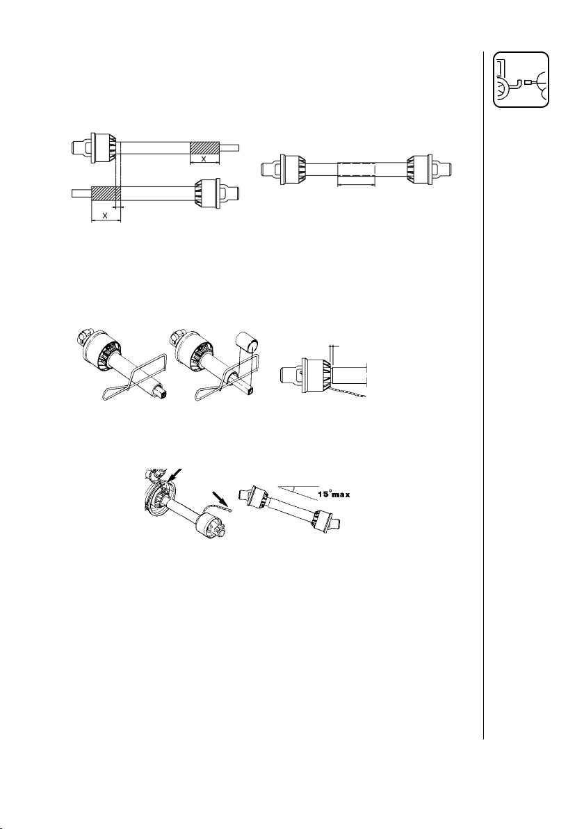
3.2 Installation Of P.T.O. Shaft (continued)
3. If P.T.O. shaft must be short ened, pull the shaft apart. Fit the two
shaft parts at tractor and spray er pump and measure how much it is
necessary to shorten the shaft. Mark the protection guards.
min. 3/4" (20mm)
Note: The shaft must al ways have a minimum over lap of 6" (150 mm)
(Fig. 3).
4. Shorten the two parts equal ly. Use a saw, and fi le the profi les
af ter wards to re move burrs (Fig. 4).
5. Grease the profi les, and reas sem ble the male and female parts.
6. Fit the shaft to tractor and spray er pump.
Note: Female part to wards tractor. Fit the chains to prevent the
pro tec tion guards from r
otating with the shaft.
Fig. 3
min. 3/4" (20mm)
Fig. 4
Fig. 5
min. 6" (150mm)
7. To ensure long life of the P.T.O. shaft, try to avoid work ing an gles
great er than 15° (Fig. 5).
15HARDI® N-SERIES 3-PT SPRAYER DIAPHRAGM OPERATOR'S MANUAL
Page 18
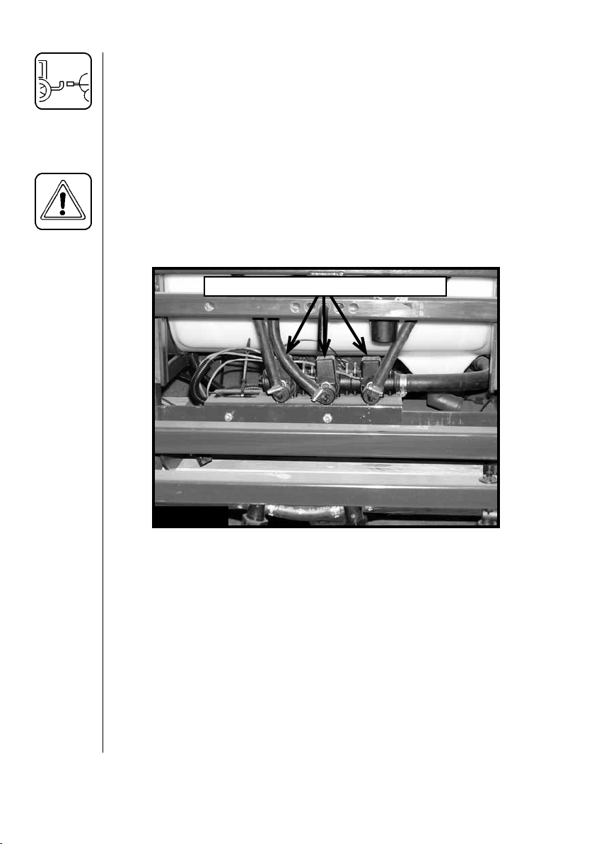
3.3 Power Supply (electric controls only)
A 12 Volt DC power supply is required to operate the electrical boom
distribution valve solenoids (Fig. 6). Connect the power supply wiring
harness as follows:
Red wire to positive (+) and Black wire to negative (-).
IMPORTANT: Do not connect to the starter motor or generator/alternator. Warranty is void if this is done.
The power supply wiring harness is equipped with a 7.5 Amp inline
fuse to protect the control box.
DISTRIBUTION V AL VE SOLENOIDS
Fig. 6
16 HARDI® N-SERIES 3-PT SPRAYER DIAPHRAGM OPERATOR'S MANUAL
Page 19
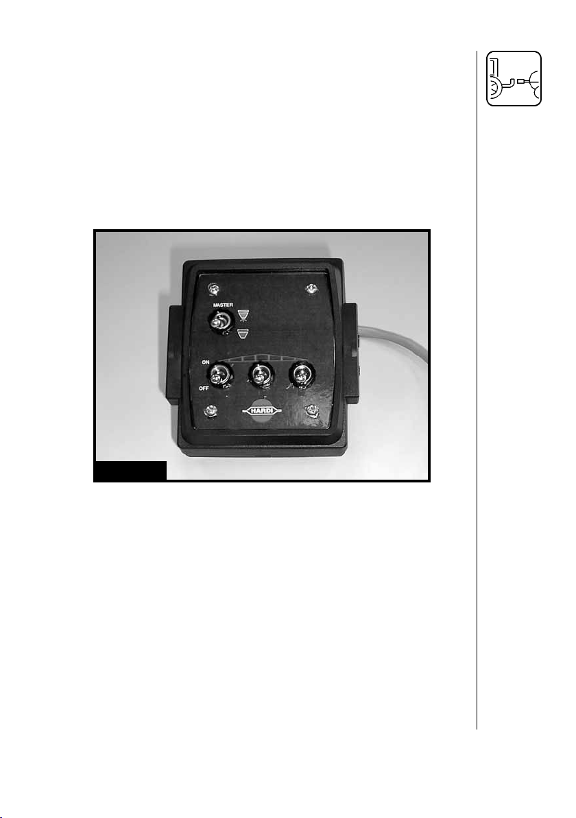
3.4 Control box (electric controls only)
The HARDI® N-series 3-PT sprayer equipped with electric controls
uses an electrical control box for master on/off control and individual
boom section on/off control. An optional rate controller box is also
available.
1. Mount the control box in a convenient location near the operator.
2. Route the power supply (installed in section 3.3) to the small plug on
the control box.
3. Route the main wiring harness from the sprayer to the large plug on
the control box.
Fig. 7
17HARDI® N-SERIES 3-PT SPRAYER DIAPHRAGM OPERATOR'S MANUAL
Page 20

4.0 OPERATING INSTRUCTIONS
4.1 Filling The Main Tank (all models)
Water is fi lled into the tank by re mov ing the tank lid located at the
center of sprayer tank. It is rec om mend ed to use water as clean as
possible for spraying pur pos es. Fill water through the strainer basket
(optional) to pre vent foreign par ti cles from entering the tank.
WARNING: DO NOT LET THE FILLING HOSE ENTER THE TANK.
KEEP IT OUT SIDE THE TANK, POINTING TO WARDS
THE FILLING HOLE (FIG. 8). IF THE END OF THE
HOSE IS BENEATH THE SURFACE OF THE
TANK CONTENTS AND THE WATER SUPPLY
STOPS, CHEMICALS
MAY BE SIPHONED
BACK AND CONTAMINA TE THE WA TER
SUPPLY SOURCE
AND LINES.
4.2 Filling The Clean Water Tank (optional)
Unscrew the clean water tank lid and fi ll with clean water only.
IMPORTANT: The water from this tank is only for hand washing,
cleaning blocked nozzles, etc.
Fig. 8
WARNING: ALTHOUGH THE HANDWASH T ANK IS
ONL Y FILLED WITH CLEAN WATER,
THE WATER MUST NEVER BE USED
FOR DRINKING, DUE TO THE SMALL
RISK OF CONTAMINATION WHILE
FILLING, ETC.
Fig. 9
18 HARDI® N-SERIES 3-PT SPRAYER DIAPHRAGM OPERATOR'S MANUAL
Page 21
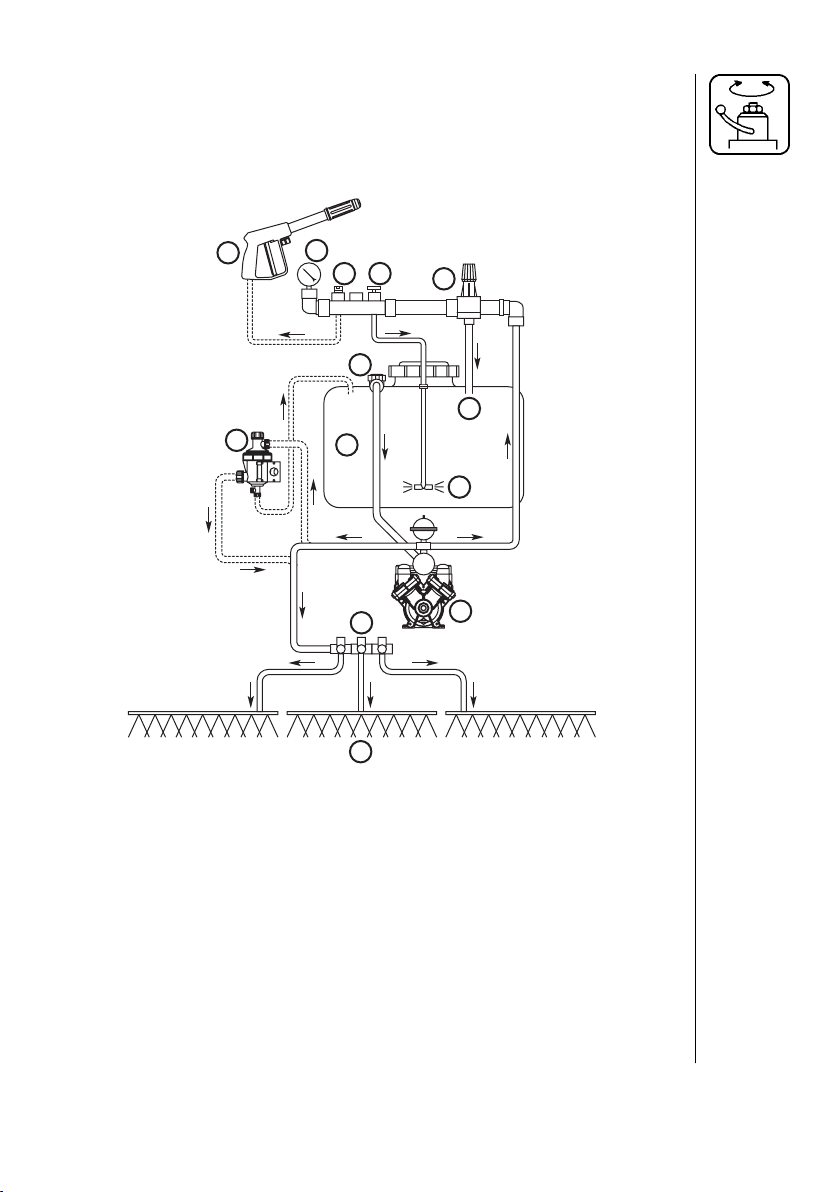
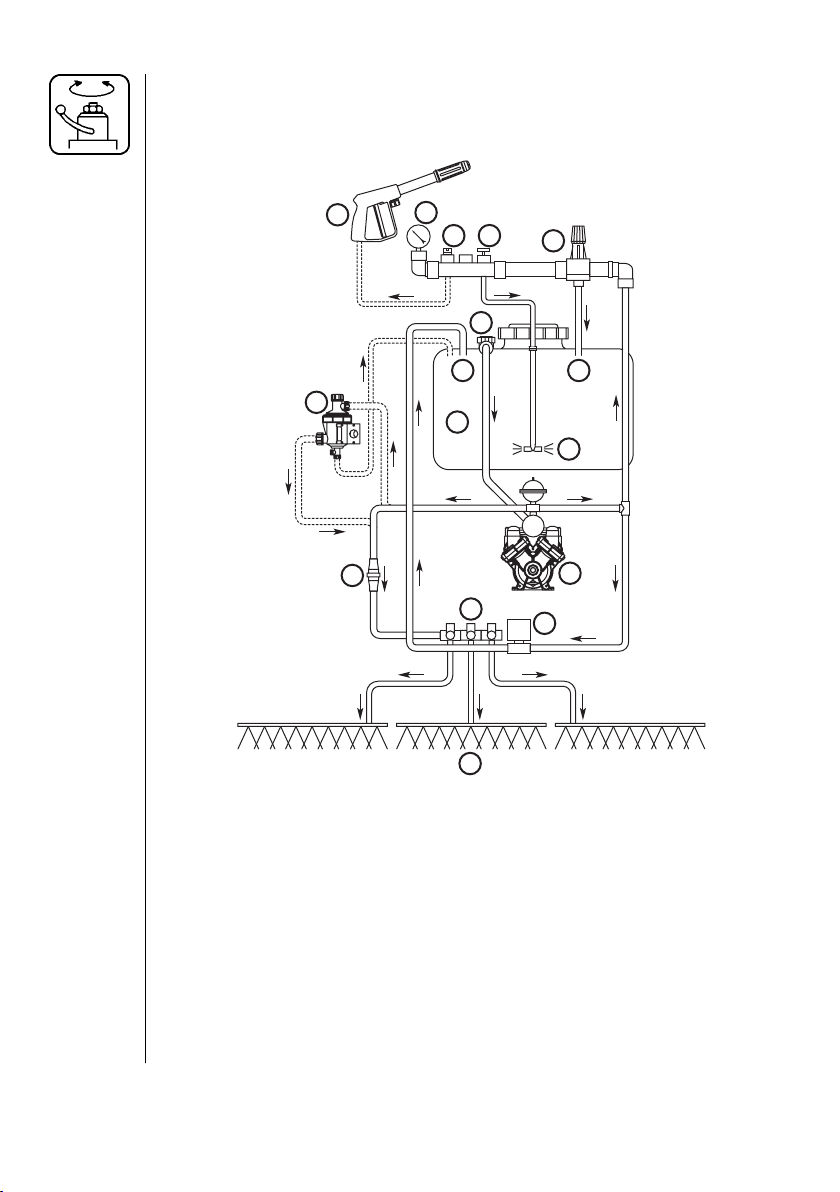
4.3 EC-3 Standard Plumbing Diagram
Review and study the following diagram. By following the fl ow through
the diagram, you will better understand the various functions of your
sprayer system.
7
11
6
4
5
1
9
12
13
3
10
8
2
Fig. 10
1. Top Suction 8. Agitation
2. Diaphragm Pump 9. Tank
3. Pressure Control Valve 10. Bypass Return
4. Agitation Valve 11. Self-Cleaning Filter (optional)
5. Spraygun Valve (optional) 12. Boom Distribution Valves
6. System Pressure Gauge 13. Boom
7. Spraygun (optional)
19HARDI® N-SERIES 3-PT SPRAYER DIAPHRAGM OPERATOR'S MANUAL
Page 22
4.4 EC-3 Plumbing Diagram w/optional Rate Controller
Review and study the following diagram. By following the fl ow through
the diagram, you will better understand the various functions of your
sprayer system.
7
11
14
6
4
5
1
10
9
12
13
3
10
8
2
15
Fig. 11
1. Top Suction 9. Tank
2. Diaphragm Pump 10. Bypass Returns
3. Pressure Relief Valve* 11. Self-Cleaning Filter (optional)
4. Agitation Valve 12. Boom Distribution Valves
5. Spraygun Valve (optional) 13. Boom
6. System Pressure Gauge 14. Flowmeter
7. Spraygun (optional) 15. Pressure Regulator
8. Agitation
*Turn Pressure Relief Valve clockwise all the way in when used with
the optional Rate Controller. Refer to Maverick Operator's manual for
adjustment of the controls.
20 HARDI® N-SERIES 3-PT SPRAYER DIAPHRAGM OPERATOR'S MANUAL
Page 23
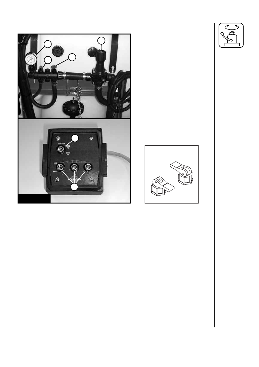
4.5 Adjustment of the EC-3 Electric Controls
2
4
3
1
SPRAYER CONTROLS:
1. Pressure control valve
2. System Pressure gauge
3. Agitation valve
4. Spraygun valve (optional)
CONTROL BOX:
5. Master On/Off Switch
5
6. Distribution Switches
SPRAYGUN
VAL VE
OFF
6
Fig. 12
ON
Boom Operation
1. Choose the correct nozzle. Make sure that all nozzles are the same
type and capacity. Refer to section 5.0 for nozzle selection and
calibration.
2. Locate your sprayer in a suitable location to spray water from the
boom. Fill the tank with clean water (see section 4.1).
3.
Turn the Pressure Control Valve 1 (Fig. 12) counter clockwise all the
way out.
4. Set Master On/Off boom switch 5 and individual boom switches 6
(Fig. 12) "ON". Set spraygun valve 4 (Fig. 12) "OFF".
5. With the tractor in neutral, engage the P.T.O. to start the pump.
Adjust the R.P.M.'s to normal operating speed.
6. Increase pressure by turning Pressure Control Valve 1 (Fig. 12)
clockwise. Adjust until the pressure gauge 2 (Fig. 12) reaches the
desired pressure (turn Pressure Control Valve counter clockwise to
decrease pressure).
21HARDI® N-SERIES 3-PT SPRAYER DIAPHRAGM OPERATOR'S MANUAL
Page 24

Operating the Spraygun (optional)
7. Set spraygun valve 4 (Fig. 12) "ON" and set Master On/Off boom
switch 5 (Fig. 12) "OFF".
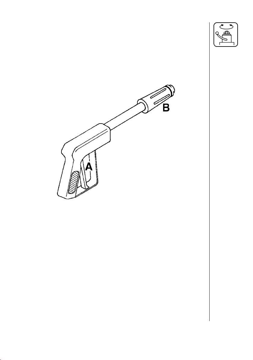
8. Then depress the red handle A (Fig. 13) to spray fl uid from the
spraygun. Check the pressure on the system pressure gauge 2 (Fig.
12) and follow step 6 to adjust.
9. To adjust the spray pattern, turn the black handle B (Fig. 13) OUT for
a narrow spray pattern for long distances and IN for a wide pattern
for more coverage at close distances.
Fig. 13
Agitation Adjustment
Ag i ta tion is nec es sary to keep the so lu tion in your tank prop er ly mixed.
Con sult your chem i cal sup pli er for the rec om mend ed amount of ag i ta tion.
In gen er al, max i mum agitation is required but some products tend to
foam easily. To reduce foaming in some instances anti-foaming agents
may be added to the tank (Refer to chemical label). When running low
liquid levels in the tank, agitation may be reduced to fa cil i tate pump
priming and avoid pressure fl uc tu a tions. Make sure that you have ad just ed the agitation properly before sprayer calibration.
Turn the agitation valve 3 (Fig. 12) clockwise to reduce the agitation
fl ow. Turn the valve counter-clockwise to in crease the agitation fl ow.
22 HARDI® N-SERIES 3-PT SPRAYER DIAPHRAGM OPERATOR'S MANUAL
Page 25

4.6 ET-3 Manual Control Plumbing Diagram
Review and study the following diagram. By following the fl ow through
the diagram, you will better understand the various functions of your
sprayer system.
7
6
13
5 12
9
4
3
1
10
8
2
11
Fig. 14
1. Top Suction 8. Agitation
2. Diaphragm Pump 9. Tank
3. Pressure Control Valve 10. Bypass Return
4. Agitation Valve 11. Self-Cleaning Filter (optional)
5. Spraygun Valve (optional) 12. Boom Distribution Valves
6. System Pressure Gauge 13. Boom
7. Spraygun (optional)
23HARDI® N-SERIES 3-PT SPRAYER DIAPHRAGM OPERATOR'S MANUAL
Page 26

4.7 Adjustment of the ET-3 Manual Controls
3
1
2
5
Fig. 15
4
1. Pressure control valve
2. Distribution valves
3. System pressure gauge
4. Agitation valve
5. Spraygun valve (optional)
ON
OFF
Boom Operation
1. Choose the correct nozzle. Make sure that all nozzles are the same
type and capacity. Refer to section 5.0 for nozzle selection and
calibration.
2. Locate your sprayer in a suitable location to spray water from the
boom. Fill the tank with clean water (see section 4.1).
3.
Turn the Pressure Control Valve 1 (Fig. 15) counter clockwise all the
way out.
4. Set the three distribution valves 2 (Fig. 15) to the ON position. Set
spraygun valve 5 (Fig. 15) to the OFF position.
5. With the tractor in neutral, engage the P.T.O. to start the pump.
Adjust the R.P.M.'s to normal operating speed.
6. Increase pressure by turning Pressure Control Valve 1 (Fig. 15)
clockwise. Adjust until the pressure gauge 3 (Fig. 15) reaches the
desired pressure (turn Pressure Control Valve counter clockwise to
decrease pressure).
24 HARDI® N-SERIES 3-PT SPRAYER DIAPHRAGM OPERATOR'S MANUAL
Page 27
Operating the Spraygun (optional)
7. Set the three distribution valves 2 (Fig. 15) to the OFF position. Set
spraygun valve 5 (Fig. 15) to the ON position.
8. Then depress the red handle A (Fig. 16) to spray fl uid from the
spraygun. Check the pressure on the system pressure gauge 3 (Fig.
15) and follow step 6 to adjust.
9. To adjust the spray pattern, turn the black handle B (Fig. 16) OUT for
a narrow spray pattern for long distances and IN for a wide pattern
for more coverage at close distances.
Fig. 16
Agitation Adjustment
Ag i ta tion is nec es sary to keep the so lu tion in your tank prop er ly mixed.
Con sult your chem i cal sup pli er for the rec om mend ed amount of ag i ta tion.
In gen er al, max i mum agitation is required but some products tend to
foam easily. To reduce foaming in some instances anti-foaming agents
may be added to the tank (Refer to chemical label). When running low
liquid levels in the tank, agitation may be reduced to fa cil i tate pump
priming and avoid pressure fl uc tu a tions. Make sure that you have ad just ed the agitation properly before sprayer calibration.
Turn the agitation valve 4 (Fig. 15) clockwise to reduce the agitation
fl ow. Turn the valve counter-clockwise to in crease the agitation fl ow.
25HARDI® N-SERIES 3-PT SPRAYER DIAPHRAGM OPERATOR'S MANUAL
Page 28

4.8 ET-2 Manual Control Plumbing Diagram
Review and study the following diagram. By following the fl ow through
the diagram, you will better understand the various functions of your
sprayer system.
7
6
13
5 12
4
3
1
10
9
8
2
11
Fig. 17
1. Top Suction 8. Agitation
2. Diaphragm Pump 9. Tank
3. Pressure Control Valve 10. Bypass Return
4. Agitation Valve 11. Self-Cleaning Filter (optional)
5. Spraygun Valve (optional) 12. Boom Distribution Valves
6. System Pressure Gauge 13. Pasture Sprayer Nozzles
7. Spraygun (optional)
26 HARDI® N-SERIES 3-PT SPRAYER DIAPHRAGM OPERATOR'S MANUAL
Page 29

4.9 Adjustment of the ET-2 Manual Controls
3
1
2
5
Fig. 18
4
1. Pressure control valve
2. Distribution valves
3. System pressure gauge
4. Agitation valve
5. Spraygun valve (optional)
ON
OFF
Operating the Pasture Sprayer Nozzles
1. Choose the correct pasture sprayer nozzles (Section 5.2). Make sure
that both nozzles are the same type and capacity.
2. Locate your sprayer in a suitable location to spray water from the
boom. Fill the tank with clean water (see section 4.1).
3.
Turn Pressure Control Valve 1 (Fig. 18) counter clockwise all the way.
4. Set the two distribution valves 2 (Fig. 18) to the ON position. Set
spraygun valve 5 (Fig. 18) to the OFF position.
5. With the tractor in neutral, engage the P.T.O. to start the pump.
Adjust the R.P.M.'s to normal operating speed.
6. Increase pressure by turning Pressure Control Valve 1 (Fig. 18)
clockwise. Adjust until the pressure gauge 3 (Fig. 18) reaches the
desired pressure (turn Pressure Control Valve counter clockwise to
decrease pressure).
27HARDI® N-SERIES 3-PT SPRAYER DIAPHRAGM OPERATOR'S MANUAL
Page 30

Operating the Spraygun (optional)
7. Set the two distribution valves 2 (Fig. 18) to the OFF position. Set
spraygun valve 5 (Fig. 18) to the ON position.
8. Then depress the red handle A (Fig. 19) to spray fl uid from the
spraygun. Check the pressure on the system pressure gauge 3 (Fig.
18) and follow step 6 to adjust.
9. To adjust the spray pattern, turn the black handle B (Fig. 19) OUT for
a narrow spray pattern for long distances and IN for a wide pattern
for more coverage at close distances.
Fig. 19
Agitation Adjustment
Ag i ta tion is nec es sary to keep the so lu tion in your tank prop er ly mixed.
Con sult your chem i cal sup pli er for the rec om mend ed amount of ag i ta tion.
In gen er al, max i mum agitation is required but some products tend to
foam easily. To reduce foaming in some instances anti-foaming agents
may be added to the tank (Refer to chemical label). When running low
liquid levels in the tank, agitation may be reduced to fa cil i tate pump
priming and avoid pressure fl uc tu a tions. Make sure that you have ad just ed the agitation properly before sprayer calibration.
Turn the agitation valve 4 (Fig. 18) clockwise to reduce the agitation
fl ow. Turn the valve counter-clockwise to in crease the agitation fl ow.
28 HARDI® N-SERIES 3-PT SPRAYER DIAPHRAGM OPERATOR'S MANUAL
Page 31

4.10 BK-3 Manual Control Plumbing Diagram
Review and study the following diagram. By following the fl ow through
the diagram, you will better understand the various functions of your
sprayer system.
12
7
10
9
13
6
1
10
14
3
8
2
4
5
11
Fig. 20
1. Top Suction 8. Agitation
2. Diaphragm Pump 9. Tank
3. HARDI-MATIC 10. Bypass Returns
4. Agitation Valve 11. Self-Cleaning Filter (optional)
5. Spraygun Valve (optional) 12. Boom Distribution Valves with
6. Pressure Filter with pressure equalization
pressure gauge 13. Boom
7. Spraygun (optional) 14. On/Off Valve
29HARDI® N-SERIES 3-PT SPRAYER DIAPHRAGM OPERATOR'S MANUAL
Page 32

4.11 Adjustment of the BK-3 Manual Controls
2
A
6
5
B
B
3
4
A
Fig. 21
1. Choose the correct nozzle. Make sure that all nozzles are the same
type and capacity. Refer to section 5.0 for nozzle selection and
calibration.
2. Locate your sprayer in a suitable location to spray water from the
boom. Fill the tank with clean water (see section 4.1).
3. Open or close lever 1 (Fig. 21) depending on whether pressure
agitation is required (Remember pressure agitation takes 5% to 10%
of pump output).
4. Turn main On/Off handle 2 (Fig. 21) to ON position A.
5. Set all hand levers 3 (Fig. 21) on the distribution valves to ON
position A.
6. Turn the HARDI-MATIC valve 4 (Fig. 21) counter-clockwise all the
way out.
7. With the tractor in neutral, engage the P.T.O. to start the pump.
Adjust the R.P.M.'s to normal operating speed.
1
Note: The P.T.O. revolutions must be kept between 300-600 R.P.M. for
the HARDI-MATIC to function properly.
8. Increase pressure by turning the HARDI-MATIC valve 4 (Fig. 21)
clockwise. Adjust until the pressure gauge 6 (Fig. 21) reaches the
desired pressure (turn HARDI-MATIC valve counter clockwise to
decrease pressure).
30 HARDI® N-SERIES 3-PT SPRAYER DIAPHRAGM OPERATOR'S MANUAL
Page 33

Adjustment of Pressure Equalization
Note: Adjust the constant boom section pressure one section at a time
as follows: (Start with the valve turned closed before adjusting).
9. Place the fi rst boom distribution valve lever 3 (Fig. 21) in the OFF
position B.
10. Turn the adjusting screw 5 (Fig. 21) until the pressure gauge 6
(Fig. 21) again shows the same pressure as in step 8 (Turn the
screw clockwise for higher pressure, counter clockwise for lower
pressure).
11. Turn the boom distribution valve lever 3 (Fig. 21) back to the ON
position A.
12. Repeat steps 9 through 11 for the remaining boom section valves.
Note: Hereafter adjustment of the constant boom pressure will only be
needed if you change to nozzles with other capacities, but not
required if only changing pressure or application rate using the
same nozzles.
Operating the Control Unit while driving
13. In order to shut off the entire boom, turn the ON/OFF handle 2 (Fig.
21) to OFF position B. This returns the pump output to the tank
through the return system. The diaphragm anti-drip valves ensure
instantaneous closing of all nozzles.
In order to shut off one or more boom sections, turn the boom
distribution lever(s) 3 (Fig. 21) of the unneeded boom section(s)
to OFF position B. The constant pressure device ensures that
the pressure does not increase in the section(s) which are still
operating.
31HARDI® N-SERIES 3-PT SPRAYER DIAPHRAGM OPERATOR'S MANUAL
Page 34

Operating the Spraygun (optional)
14. Set the three distribution valves 3 (Fig. 21) to the OFF position. Set
spraygun valve 5 (Fig. 20) to the ON position.
15. Then depress the red handle A (Fig. 22) to spray fl uid from the
spraygun. Check the pressure on the system pressure gauge 6
(Fig. 21) and follow step 8 to adjust.
16. To adjust the spray pattern, turn the black handle B (Fig. 22) OUT
for a narrow spray pattern for long distances and IN for a wide
pattern for more coverage at close distances.
Fig. 22
32 HARDI® N-SERIES 3-PT SPRAYER DIAPHRAGM OPERATOR'S MANUAL
Page 35
4.12 Operation Of The Tank Drain Valve (all models)
WARNING: BEFORE USING THE TANK DRAIN, VERIFY THAT
DISPOSAL OF WASTE IS DONE ACCORDING TO
CHEMICAL LABEL INSTRUCTIONS AND LOCAL
REGULATIONS.
The HARDI
®
N-series 3-PT sprayer is equipped with a top operated
tank drain valve.
The top operated tank drain valve handle is located near the tank
lid. To open the drain valve, turn the red drain valve handle (Fig. 23)
counter-clockwise.
To close the drain valve, turn the handle (Fig. 23) clockwise.
TOP OPERATED TANK DRAIN
To open
Fig. 23
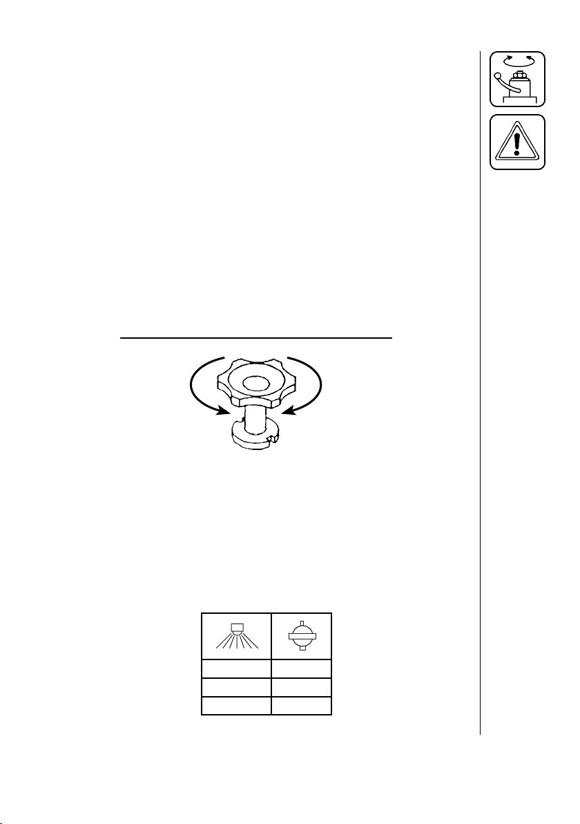
4.13 Adjustment of Air Pressure in Pressure Damper
(All models)
The air pressure in the damper on the HARDI® diaphragm pump is factory preset at 30 psi (2 bar). This is suitable for nozzle spray pressures
between 45 psi (3 bar) and 225 psi (15 bar). If different nozzle pressures are required, set pressure damper at pressures indicated.
To close
PSI (BAR) PSI (BAR)
20-45 (1-3) 0-15 (0-1)
45-255 (3-15) 15-45 (1-3)
33HARDI® N-SERIES 3-PT SPRAYER DIAPHRAGM OPERATOR'S MANUAL
Page 36

4.14 Self Cleaning Fil ter (optional)
This fi lter automatically fl ushes out par ticles and chemical deposits,
re duc ing routine main te nance, nozzle plugging and operator exposure.
No ad just ments are required but different mesh screens may be installed
for various types of products. The mesh size of the fi l ter in use should
al ways be small er than the fl ow av er age of the noz zles used.
Self-Cleaning Filter
Operating Diagram
1. From pump
2. Double fi lter screen
3. Guide cone
4. To operating unit
5. Replaceable restrictor
6. Return to tank
Choice Of Correct Restrictor for S.C.F.
It is important to have a large fl ow though the self clean ing fi lter. This
is achieved by choos ing the restrictor size in re la tion to the liquid
con sump tion of the spray boom.
The hose (A) is un screwed from the self-clean ing
fi lter . Be careful not to lose the seal ball or spring
when the restrictor is put in the hose and the hose
is re fi t ted. If the re quired working pres sure can not
be ob tained, the restrictor is too large. 4 Restrictors
are supplied. Use the green one (larg est or i fi ce) fi rst.
Choose the next smaller restrictor. Start with a black
one, then a white and fi nal ly a red one.
34 HARDI® N-SERIES 3-PT SPRAYER DIAPHRAGM OPERATOR'S MANUAL
Page 37

4.15 Unfolding/Folding Boom
(All models with standard booms)
Unfolding boom into operating position
1. Remove transport lock pins A (Fig. 24) and swing boom into
operating position. Store transport lock pins in original locations so
they don't get lost.
2. Lift outer boom sections up and over to horizontal position (not
necessary for 20' MB boom). Carefully check that feed hoses do not
interfere with spray pattern.
3. Remove trapeze lock pin B (Fig. 24) to allow for self-leveling boom
feature (40' MB boom only).
Note: The trapeze lock pin may also be used to lock the boom in a
tilted position (40' MB boom only).
A
B
Fig. 24
Folding boom into transport position
1. Replace trapeze lock pin B (Fig. 24) in center position (40' MB boom
only).
2. Fold outer boom section over to rest on inner boom section (not
necessary for 20' MB boom).
3. Remove transport lock pins A (Fig. 24) and fold boom into transport
position. Secure with transport lock pins A (Fig. 24).
WARNING: MAKE ABSOLUTELY CERTAIN BOOM TRANSPORT LOCK
PINS ARE INST ALLED AND SECURED WITH CLIP PINS
BEFORE TRANSPORTING THE SPRA YER.
35HARDI® N-SERIES 3-PT SPRAYER DIAPHRAGM OPERATOR'S MANUAL
Page 38

4.15 Boom Height Adjustment
(All models with standard booms)
Correct boom height is very important in order to achieve the most
optimal spray pattern. Small adjustments of the boom height can usually be made with the 3-point suspension from the tractor - raising or
lowering the sprayer.
In crops where greater adjustments are needed, the boom height can
be changed manually by removing the 4 bolts holding the boom to the
frame.
Note: This is best done by 2 people or with a mechanical hoist.
36 HARDI® N-SERIES 3-PT SPRAYER DIAPHRAGM OPERATOR'S MANUAL
Page 39

5.0 NOZZLE SELECTION
Correct selection of nozzles and calibration of the sprayer are critical to
achieve accurate and cost effective use of farm crop protection prod ucts.
Your HARDI® N-series sprayer has been supplied with standard nozzles. Should you wish a different application rate or different type of
nozzle, HARDI® manufactures a nozzle for virtually every need.
IMPORTANT: Always consult your chemical supplier for rec om mend ed chemical rate and water application rate. Always wear
protective gloves when handling nozzles.
5.1 Boom Nozzle Selection
(All models with standard booms)
The following tables show what types of spray nozzles are suitable for
different applications. It is important to use the correct nozzle.
HARDI® ISO COLOR TIPS™
110 degree fl at fan, one piece
cap and nozzle; color coded for
fl ow rate se lec tion.
For herbicides, insecticides, and
fertilizer applications. 50, 80, and
100 mesh screens are normally
used.
F110
HARDI® ISO LowDrift COLOR
TIPS™ 110 degree fl at f an, one
piece cap and nozzle, 1553 solid
stream nozzle; color coded for
fl ow rate selection.
In-Line Filters will normally be
used.
LD110
37HARDI® N-SERIES 3-PT SPRAYER DIAPHRAGM OPERATOR'S MANUAL
Page 40

HARDI® INJET™ NOZZLES; air
inclusion nozzles with removable
restrictor. Color coded for fl ow
rate selection. In-Line Filters will
normally be used.
FLAT SPRAY NOZZLES in 65
degree, 80 degree, and 110
degree spray angles. For her bi cides, insecticides, and fertilizer
applications. 50, 80, and 100
mesh screens are normally
used.
FLOOD NOZZLES set at 40°
spacing. Designed for high
vol ume application.
HOLLOW CONE NOZZLES
for high pressure and high
vol ume insecticide application
in row crops. 1553 nozzles are
AL WA YS used with swirl plates
shown below EXCEPT when
used as solid stream nozzles.
50, 80, or 100 mesh screens
are normally used with these
nozzles
SWIRL PLA TE used in con junc tion with cone nozzle to create
desired spray pattern. These
swirls work with 1553 series
cone nozzles. Grey , blue, or black
swirls are used to create hollow
cone effect. White swirls are used
to create full cone effect.
4665-65 degree
2080-80 degree
4110-110 degree
Part # 330013-
O-ring
4598
1553
Must add swirl
to produce
hollow cone
pattern
Grey
Blue
Black
White
38 HARDI® N-SERIES 3-PT SPRAYER DIAPHRAGM OPERATOR'S MANUAL
Page 41

HOLLOW CONE CERAMIC
NOZZLES for high pressure
and high volume fungicide and
insecticide application.
LARGE DROPLET HOLLOW
CONE NOZZLE for use where
drift must be kept to a minimum.
These nozzles must always be
fi tted with 1553 nozzles and g re y
swirl plates. 50, 80 or 100 mesh
screens are normally used with
these nozzles.
LARGE DROPLET FLA T SPRAY
TIP IN 150 DEGREE SPRAY
ANGLE. Always used in conjunc-
tion with 1553-14-16-18 or 20
cone nozzle. 50, 80 or 100 mesh
screens are normally used with
these nozzles.
SOLID STREAM NOZZLE for
high volume liquid fertilizer
ap pli ca tion. In this application, the
1553 nozzle is always used with
330013 o-ring and 50, 80 or 100
mesh screens.
HARDI® QUINTASTREAM
5 HOLE LIQUID FERTILIZER
NOZZLE Five streams of liquid
are distributed at different angles
and fl ows. Highest fl ow is from
the middle stream and lowest in
the outer; overlapping streams.
This allows for boom mov ements
that do not infl uence distribution.
Boom heights of 20" can be used
as safely as 30".
1299
371077
371551
1553 less swirl
372011
thru
372019
39HARDI® N-SERIES 3-PT SPRAYER DIAPHRAGM OPERATOR'S MANUAL
Page 42
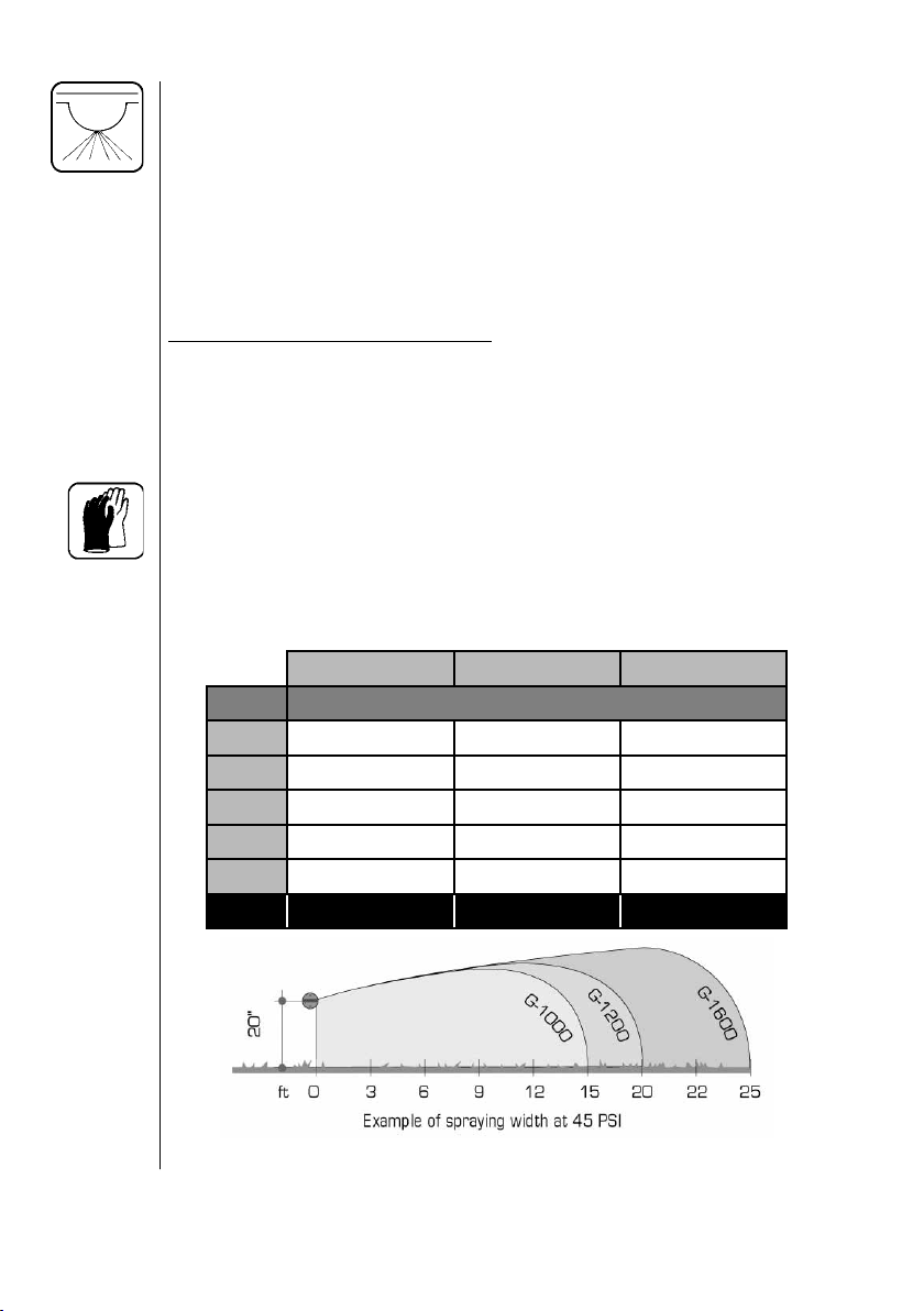
5.2 Giant End Nozzle Selection (Pasture Sprayer only)
The two opposite mounted HARDI® Giant End Nozzles are available in
three different sizes and provide a maximum spray width of 30', 40' or
50' (10m, 12m or 16m) under optimal spraying conditions at the recommended 20" (50 cm) nozzle spray heights (Fig. 25).
For sprayers equipped with "Boom Buster" nozzles (Evergreen Products, Inc.), consult the supplied nozzle application chart.
Giant End Nozzle characteristics:
• Off center spray nozzle
• Pressure range: 20 to 70 PSI
• Spray width up to 25 ft. (per nozzle)
• SYNTAL precision molded thermoplastic
IMPORTANT: Always consult your chemical supplier for rec om mend ed chemical rate and water application rate. Always wear
protective gloves when handling nozzles.
The following tables show which HARDI® Giant End Nozzles are suitable for different applications. It is important to use the correct nozzle.
G-1000 Red G-1200 White G-1600 Blue
PSI GPM
20 3.224 3.762 5.015
30 3.949 4.607 6.143
40 4.560 5.320 7.093
50 5.098 5.948 7.930
70 6.032 7.037 9.383
Part # 371556 371557 371558
Fig. 25
40 HARDI® N-SERIES 3-PT SPRAYER DIAPHRAGM OPERATOR'S MANUAL
Page 43
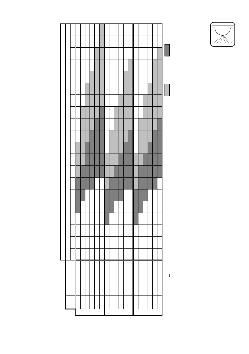
(
GALLONS PER ACRE
)
SPEED (MPH)
15-25 GPA
10-15 GPA
APPLICATION RATE
1234567891011121314151617181920
‡
Use the following table to quickly determine which nozzle and spraying speed will work best for a wide range of
Note: Using this chart will bring you very close to your desired application rate. However, you must calibrate
application rates.
your sprayer with clean water before applying chemicals (Section 5.5).
SPRAY
WIDTH (ft)
†
GPM
20 3.224 30.0 106.4 53.2 35.5 26.6 21.3 17.7 15.2 13.3 11.8 10.6 9.7 8.9 8.2 7.6 7.1 6.6 6.3 5.9 5.6 5.3
PSI*
30 3.949 30.0 130.3 65.2 43.4 32.6 26.1 21.7 18.6 16.3 14.5 13.0 11.8 10.9 10.0 9.3 8.7 8.1 7.7 7.2 6.9 6.5
40 4.560 30.0 150.5 75.2 50.2 37.6 30.1 25.1 21.5 18.8 16.7 15.0 13.7 12.5 11.6 10.7 10.0 9.4 8.9 8.4 7.9 7.5
50 5.098 30.0 168.2 84.1 56.1 42.1 33.6 28.0 24.0 21.0 18.7 16.8 15.3 14.0 12.9 12.0 11.2 10.5 9.9 9.3 8.9 8.4
60 5.575 30.0 184.0 92.0 61.3 46.0 36.8 30.7 26.3 23.0 20.4 18.4 16.7 15.3 14.2 13.1 12.3 11.5 10.8 10.2 9.7 9.2
G-1000 RED
70 6.032 30.0 199.1 99.5 66.4 49.8 39.8 33.2 28.4 24.9 22.1 19.9 18.1 16.6 15.3 14.2 13.3 12.4 11.7 11.1 10.5 10.0
20 3.762 40.0 93.1 46.6 31.0 23.3 18.6 15.5 13.3 11.6 10.3 9.3 8.5 7.8 7.2 6.7 6.2 5.8 5.5 5.2 4.9 4.7
30 4.607 40.0 114.0 57.0 38.0 28.5 22.8 19.0 16.3 14.3 12.7 11.4 10.4 9.5 8.8 8.1 7.6 7.1 6.7 6.3 6.0 5.7
40 5.320 40.0 131.7 65.8 43.9 32.9 26.3 21.9 18.8 16.5 14.6 13.2 12.0 11.0 10.1 9.4 8.8 8.2 7.7 7.3 6.9 6.6
50 5.948 40.0 147.2 73.6 49.1 36.8 29.4 24.5 21.0 18.4 16.4 14.7 13.4 12.3 11.3 10.5 9.8 9.2 8.7 8.2 7.7 7.4
60 6.500 40.0 160.9 80.4 53.6 40.2 32.2 26.8 23.0 20.1 17.9 16.1 14.6 13.4 12.4 11.5 10.7 10.1 9.5 8.9 8.5 8.0
70 7.037 40.0 174.2 87.1 58.1 43.5 34.8 29.0 24.9 21.8 19.4 17.4 15.8 14.5 13.4 12.4 11.6 10.9 10.2 9.7 9.2 8.7
G-1200 WHITEG-1600 BLUE
20 5.015 50.0 99.3 49.6 33.1 24.8 19.9 16.5 14.2 12.4 11.0 9.9 9.0 8.3 7.6 7.1 6.6 6.2 5.8 5.5 5.2 5.0
30 6.143 50.0 121.6 60.8 40.5 30.4 24.3 20.3 17.4 15.2 13.5 12.2 11.1 10.1 9.4 8.7 8.1 7.6 7.2 6.8 6.4 6.1
40 7.093 50.0 140.4 70.2 46.8 35.1 28.1 23.4 20.1 17.6 15.6 14.0 12.8 11.7 10.8 10.0 9.4 8.8 8.3 7.8 7.4 7.0
50 7.930 50.0 157.0 78.5 52.3 39.3 31.4 26.2 22.4 19.6 17.4 15.7 14.3 13.1 12.1 11.2 10.5 9.8 9.2 8.7 8.3 7.9
60 8.666 50.0 171.6 85.8 57.2 42.9 34.3 28.6 24.5 21.4 19.1 17.2 15.6 14.3 13.2 12.3 11.4 10.7 10.1 9.5 9.0 8.6
70 9.383 50.0 185.8 92.9 61.9 46.4 37.2 31.0 26.5 23.2 20.6 18.6 16.9 15.5 14.3 13.3 12.4 11.6 10.9 10.3 9.8 9.3
Fig. 26
† GPM per nozzle
the nozzle ‡ Spray width is the total width (2 nozzles) at 20" spray height
* PSI is the pressure at
41HARDI® N-SERIES 3-PT SPRAYER DIAPHRAGM OPERATOR'S MANUAL
Page 44

5.3 Spraygun Nozzle Selection (All models)
The 1099-20 nozzle (HARDI® ref. no. 371314) is the standard nozzle
for the spraygun. This nozzle supplies the following rates in U.S. gallons per minute at the given pressures:
GPM
NOZZLE
1099-20
PSI
20
30
40
50
60
70
100
150
200
0.678
0.829
0.956
1.068
1.169
1.261
1.504
1.840
2.123
0.538
0.661
0.766
0.857
0.940
1.018
1.222
1.500
1.736
Other size 1099 nozzles are available from your HARDI
®
Dealer.
42 HARDI® N-SERIES 3-PT SPRAYER DIAPHRAGM OPERATOR'S MANUAL
Page 45

5.4 Calibration (All models with standard booms)
WARNING: ALWAYS CALIBRATE YOUR SPRAYER WITH CLEAN
WATER ONLY! IN ADDITION, WEAR PROTECTIVE
CLOTHING WHEN CALIBRATING YOUR SPRAYER!
Why must you calibrate a sprayer?
A nozzle selection chart will tell you what application rate you should
expect. V ariations due to nozzle wear, errors in pressure adjustment, and
tractor speedometer can result in a possible error in application rate.
How do you calibrate a sprayer?
Calibration kits are available from HARDI
®
, #818493 for US gallons &
#818492 for metric calibration.
Following are some tips to remember when using the calibration kit
method:
• When determining the length of time required to drive the recommended
distance, drive in actual fi eld conditions with a half-full tank.
• Repeat the test several times, each time avoiding the tracks from the
previous test. Take the average of the times recorded.
• Calibration of the sprayer should be completed at the beginning of the
season and repeated after every 2 to 3 full days of spraying, and every
time you change volume rate or use new nozzles.
• Before you calibrate, check the fl ow of each nozzle. If it puts out more
than 10% of its original volume, replace it.
Select your calibration method: Ounce method or Formula method.
Then follow the steps described in the corresponding section(s):
43HARDI® N-SERIES 3-PT SPRAYER DIAPHRAGM OPERATOR'S MANUAL
Page 46

Ounce Method
1. Determine how long it takes to cover the test strip. Use the following
chart to determine the length of your test strip. Row width f or broadcast
application is equal to your nozzle spacing. For your drop nozzle or
band application, use row spacing.
Row width or nozzle spacing (in.) Distance (ft.)
40 102
38 107
36 113
34 120
32 127
30 136
28 146
26 157
24 170
22 185
20 204
18 227
16 255
14 291
2. Measure the amount of time it takes you to travel the test strip when
throttle is set at spraying speed.
3. In a container (with oz. measurements), catch the spra y from one nozzle
for that amount of time. F or drop or band nozzles, catch the spra y from
all nozzles for the row.
4. Read the ounces in the container. That is the actual U.S. GPA applied.
(ounces = GPA)
44 HARDI® N-SERIES 3-PT SPRAYER DIAPHRAGM OPERATOR'S MANUAL
Page 47

Formula Method
1. Check your spraying speed. Measure a test strip of at least 200 feet
(300 feet is ideal). T rav el the distance at the speed you plan on spraying
and record the time it takes to trav el the distance. Read from the chart
or use the formula to fi nd your exact travel speed.
Travel Time (in seconds)
Speed in MPH 200 ft. 300 ft.
3.0 45 68
3.5 39 58
4.0 34 51
Formula: 4.5 30 45
distance (ft.) x 0.68
seconds 6.0 23 34
7.0 19 29
7.5 18 27
8.0 17 26
9.0 15 23
= MPH
5.0 27 41
2. Calculate the required nozzle output. Use either the nozzle wheel (if
nozzle spacing is 20 inches), or this formula:
Formula: Formula:
5940
GPA x MPH x W (in.)
GPM =
GPM =
10 x 7 x 20
5940
= .24 GPM
Note: W= • Nozzle spacing (in inches) for broadcast application.
• Row spacing (in inches) divided by number of nozzles
per row for drop nozzle application.
• Sprayed band width or swath width (in inches) for band
application divided by number of nozzles per band.
• Note that on the nozzle wheel, W = 20 inches.
3. Set correct pressure. Read the required pressure from the nozzle table
in the nozzle catalogue or nozzle wheel. With clean water in the tank
and line, turn on the sprayer and set the target pressure. Collect the
spray from one nozzle for one minute in a container. Adjust pressure
until you collect the precise GPM called for.
45HARDI® N-SERIES 3-PT SPRAYER DIAPHRAGM OPERATOR'S MANUAL
Page 48

Calibration For Carriers Other Than Water
Use the following water rate conversion chart to determine the right
conversion factor. When you've determined the new converted GPM or
GPA, you can follow the steps on either the pressure or ounce method
of calibration.
Weight of solution Specifi c Gravity Conversion Factors
7.00 lbs/gal .84 .92
8.00 lbs/gal .96 .98
8.34 lbs/gal-water 1.00 1.00
9.00 lbs/gal 1.08 1.04
10.00 lbs/gal 1.20 1.10
10.65 lbs/gal-28% N 1.28 1.13
11.00 lbs/gal 1.32 1.15
12.00 lbs/gal 1.44 1.20
14.00 lbs/gal 1.68 1.30
Example: 20 GPA of 28% N
Then GPA (solution) x conversion factor = GPA (water)
20 GPA (28% N) x 1.13 = 22.6 GPA (water)
Calibrate for 22.6 GPA of water
For conversion to Imperial gallons per acre, multiply U.S. GPA by .833
For conversion to liters per hectare, multiply U.S. GPA by 9.34
For conversion to liters per acre, multiply U.S. GPA by 3.78
Formula for tractor speed: Distance (in feet) x .682
= MPH
Second
46 HARDI® N-SERIES 3-PT SPRAYER DIAPHRAGM OPERATOR'S MANUAL
Page 49

5.5 Calibration (Pasture sprayer model only)
WARNING: ALWAYS CALIBRATE YOUR SPRAYER WITH CLEAN
WATER ONLY! IN ADDITION, WEAR PROTECTIVE
CLOTHING WHEN CALIBRATING YOUR SPRAYER!
Why must you calibrate a sprayer?
A nozzle selection chart will tell you what application rate you should
expect. Variations due to nozzle wear, errors in pressure adjustment,
and tractor speedometer can result in a possible error in application
rate.
How do you calibrate a sprayer?
Calibration kits are available from HARDI®, #818493 for US gallons &
#818492 for metric calibration.
Following are some tips to remember when using the calibration kit
method:
• When determining the length of time required to drive the recom-
mended distance, drive in actual fi eld conditions with a half-full tank.
• Repeat the test several times, each time avoiding the tracks from the
previous test. Take the average of the times recorded.
• Calibration of the sprayer should be completed at the beginning of
the season and repeated after every 2 to 3 full days of spraying, and
every time you change volume rate or use new nozzles.
• Before you calibrate, check the fl ow of each nozzle. If it puts out more
than 10% of its original volume, replace it.
47HARDI® N-SERIES 3-PT SPRAYER DIAPHRAGM OPERATOR'S MANUAL
Page 50

Formula Method
1. Check your spraying speed. Measure a test strip of at least 200
feet (300 feet is ideal). Travel the distance at the speed you plan on
spraying and record the time it takes to travel the distance. Read
from the chart or use the formula to fi nd your exact travel speed.
Travel Time (in seconds)
Speed in MPH 200 ft. 300 ft.
3.0 45 68
3.5 39 58
4.0 34 51
Formula: 4.5 30 45
Distance (ft.) x 0.68
= MPH
5.0 27 41
Time (sec.) 6.0 23 34
7.0 19 29
7.5 18 27
8.0 17 26
9.0 15 23
2. After determining your forward speed and choosing your application
rate according to the recommendations on the chemical container,
use the following formula to calculate the total nozzle capacity:
Formula:
Total GPM =
W (ft.) x GPA x MPH
495
Note: W = Total measured sprayed width (ft.) at operating pressure.
3.
To initially calculate which nozzle to use, let W = 30 ft., 40ft. or 50 ft.
for HARDI® Giant End Nozzles G-1000 Red, G-1200 White or G1600 Blue, respectively (Fig. 24 & Fig. 25).
Example: Total sprayed width: 40 ft. (G-1200 White nozzles)
Application rate: 20 GPA
Forward speed: 7 mph
11.3 GPM =
40 ft. x 20 GPA x 7 mph
495
48 HARDI® N-SERIES 3-PT SPRAYER DIAPHRAGM OPERATOR'S MANUAL
Page 51

Calibration (continued)
4. Divide the total nozzle capacity by 2 (the number of nozzles) to get
the GPM needed per nozzle to match the speed, pressure and width
used in the calculations (Example: 11.3 ÷ 2 = 5.65 GPM).
Capacity of single nozzle in GPM =
Number of nozzles
5. For HARDI® Giant End Nozzles, use the nozzle chart (Fig. 25) to
fi nd the nozzle with the closest desired output and pressure. (The G1200 White nozzle at 50 PSI is the closest for this example at 5.948
GPM).
IMPORTANT: Al ways check actual sprayed width at operating
pressure once the correct nozzle has been chosen. Locate the
sprayer in a suitable location and use clean water to check.
6. If the measured sprayed width at operating pressure differs from the
value used in step 2, re-calculate the total nozzle capacity using the
measured sprayed width. Divide by 2 to get the nozzle capacity in
GPM needed per nozzle (step 4). This will be the corrected nozzle
capacity in GPM required from each nozzle for proper application
rate.
7. Double-check the nozzle output with a measuring jug (using clean
water at operating pressure). If the measured nozzle output matches
the required calculated output, calibration is complete.
8. If necessary, use the following formulas to adjust either the spraying
speed or operating pressure to achieve proper calibration.
Total GPM
New speed (MPH) =
Measured output (GPM)
New pressure (PSI) =
Measured output (GPM)
Note: If the operating pressure is changed, the actual spraying width
will need to be checked again. If spraying width differs, repeat
steps 6-8.
Desired output (GPM) x Previous speed (MPH)
Desired output (GPM) x Previous pressure (PSI)
49HARDI® N-SERIES 3-PT SPRAYER DIAPHRAGM OPERATOR'S MANUAL
Page 52

Calibration For Carriers Other Than Water
Use the following water rate conversion chart to determine the right
conversion factor. When you've determined the new converted GPM or
GPA, you can follow the steps in the formula method of calibration.
Weight of solution Specifi c Gravity Conversion Factors
7.00 lbs/gal .84 .92
8.00 lbs/gal .96 .98
8.34 lbs/gal-water 1.00 1.00
9.00 lbs/gal 1.08 1.04
10.00 lbs/gal 1.20 1.10
10.65 lbs/gal-28% N 1.28 1.13
11.00 lbs/gal 1.32 1.15
12.00 lbs/gal 1.44 1.20
14.00 lbs/gal 1.68 1.30
Example: 20 GPA of 28% N
Then GPA (solution) x conversion factor = GPA (water)
20 GPA (28% N) x 1.13 = 22.6 GPA (water)
Calibrate for 22.6 GPA of water
For conversion to Imperial gallons per acre, multiply U.S. GPA by .833
For conversion to liters per hectare, multiply U.S. GPA by 9.34
For conversion to liters per acre, multiply U.S. GPA by 3.78
Formula for tractor speed: Distance (in feet) x .682
= MPH
Second
50 HARDI® N-SERIES 3-PT SPRAYER DIAPHRAGM OPERATOR'S MANUAL
Page 53

6.0 MAINTENANCE
IMPORTANT: Always clean the sprayer at the end of your workday
or before servicing is done to avoid unnecessary contact with
chemicals.
In order to derive full benefi t from the sprayer for many years, the fol low ing few, but im por tant rules should be followed.
6.1 Cleaning The Sprayer
Guidelines
Read the whole label for the chem i cal used. Take note of any par tic u lar
in struc tions regarding rec om mend ed protective clothing, de ac ti vat ing
agents, etc. Read the de ter gent and de ac ti vat ing agent labels. If clean ing pro ce dures are given, follow them closely.
Be familiar with local leg is la tion regarding disposal of pes ti cides washings, man da to ry de con tam i na tion meth ods, etc. Contact the ap pro pri ate body (e.g. Dept. of Ag ri cul ture).
Cleaning starts with cal i bra tion, as a well cal i brat ed spray er will en sure
a min i mal amount of re main ing spray liquid.
It is good practice to clean the spray er immediately after use, there by
ren der ing the spray er safe and ready for the next ap pli ca tion. This also
pro longs the life of the com po nents.
It is sometimes necessary to leave spray liquid in the tank for short
pe ri ods - over night, or until the weather becomes suitable for spray ing
again. Unauthorized per sons and animals must not have ac cess to the
sprayer under these circumstances.
If the product applied is cor ro sive, it is recommended to coat all metal
parts of the sprayer before and after use with a suit able rust in hib i tor.
Remember: Clean sprayers are safe spray ers.
Clean sprayers are ready for action.
Clean sprayers can not be dam aged by chemicals and
their solvents.
51HARDI® N-SERIES 3-PT SPRAYER DIAPHRAGM OPERATOR'S MANUAL
Page 54

Cleaning
1. Dilute remaining spray liquid in the tank with at least 10 parts water
and spray the liquid out in the fi eld you have just sprayed.
Note: It is ad vis able to in crease the forward speed (dou ble if possible)
and reduce the pressure.
2. Select and use the ap pro pri ate protective clothing. Select detergent
suitable for cleaning and suit able de ac ti vat ing agents if necessary.
3. Rinse and clean sprayer and tractor ex ter nal ly. Use de ter gent if
necessary.
4. Remove all fi lters and clean them. Be careful not to damage the
mesh. Replace fi lters when the sprayer is completely clean.
5. With the pump running, rinse the inside of the tank. Re mem ber the
tank roof. Rinse and operate all com po nents and any equipment that
has been in contact with the chemical.
6. After spraying the liquid out again in the fi eld, stop the pump and fi ll
at least 1/5 of the tank with clean wa ter. Note that some chemicals
require the tank to be com plete ly fi lled. Add appropriate detergent
and/or deactivating agent, e.g. Washing soda or Triple ammonia.
Note: If a cleaning pro ce dure is given on the chemical label, follow it
closely.
7. Start the pump and op er ate all controls en abling the liquid to come
in contact with all the components. Leave the dis tri bu tion valves until
last. Some detergents and de ac ti vat ing agents work best if left in the
tank for a short period. Check the label.
8. Drain the tank and let the pump run dry. Rinse inside of tank, again
letting the pump run dry.
9. Stop the pump. If the chemicals used have a tendency to block
nozzles, re move and clean them now.
10. Replace all fi lters and noz zles and store the sprayer. If, from previ-
ous experiences, it is noted that the solvents in the chemicals are
particularly ag gres sive, store the sprayer with the tank lid open.
Note: If the sprayer is cleaned with a high pres sure cleaner we recom-
mend lu bri ca tion of the entire machine (Section 6.8).
52 HARDI® N-SERIES 3-PT SPRAYER DIAPHRAGM OPERATOR'S MANUAL
Page 55

6.2 Filters
IMPORTANT: Wear protective clothing when servicing & handling
components that have been in contact with spray liquid.
Clean fi lters ensure :
• Sprayer components such as valves, diaphr agms and operat ing unit
are not hindered or damaged during operation.
• Nozzle blockages do not occur while spray ing.
• Long life of pump. A blocked suction fi lter will result in pump cavitation.
Suction fi lter
The main fi lter protecting spray er com po nents is
the suc tion fi l ter at the top of the tank. Check
it reg u lar ly. Make sure the O-ring on the
fi lter housing is in good condition and
lubricated*.
Pressure fi lter (BK-3 Control Unit only)
The BK-3 Control unit is equipped with a built-in pressure fi lter.
Unscrew the base to check and clean the fi lter. Make sure the O-ring
on the fi lter housing is in good condition and lubricated*.
*HARDI
®
recommends using a vegetable based oil to prolong the life of
the O-ring.
53HARDI® N-SERIES 3-PT SPRAYER DIAPHRAGM OPERATOR'S MANUAL
Page 56

ISO Nozzle
Size
Pink (075)
Orange (01)
Green (015)
Yellow (02)
Suction Filter Self Cleaning
Filter (optional)
50 100 100 100
Nozzle
Screen
Inline Filters
(optional)
Lilac (025)
Blue (03)
Red (04)
& Larger
*Standard mesh
50 80 80 80
30* 50* 50* 50*
6.3 Nozzles And Fittings
Poor seals are usually caused by:
• Missing O-rings or gaskets
• Damaged or incorrectly seated O-rings
• Dry or deformed O-rings or gaskets
• Foreign materials
Therefore, in case of leaks; DO NOT overtighten. Disassemble, check
condition and position of O-ring or gasket, clean, lubricate and reassemble. For radial type seals (O-ring) hand tighten only, do not use
pliers (Fig. 27).
The O-rings need to be lubricated ALL THE WA Y AROUND before fi tting on to the nozzle tube.
Fig. 27
HARDI® recommends using a vegetable based oil to prolong the life of
the O-ring.
54 HARDI® N-SERIES 3-PT SPRAYER DIAPHRAGM OPERATOR'S MANUAL
Page 57

6.4 Replacement Of P.T.O. Shaft Protection Guards
The replacement of defective pro tec tion guards is easy to do.
1. The retaining ring A (Fig. 28) holds the base cone B (Fig. 28) and
shield bell C (Fig. 28) to the shield tube D (Fig. 28).
2. Locate the three white tabs on the retaining ring A (Fig. 28) visible
through holes on the shield bell C (Fig. 28). Pushing these tabs will
release the retaining ring A (Fig. 28).
3. Remove the base cone B (Fig. 28) and shield bell C (Fig. 28) from
the shield tube D (Fig. 28).
4. Assemble again in reverse order, using new parts where necessary.
5. Apply grease (Section 6.8).
Use only genuine HARDI
B
A
C
®
spare parts to service the P.T.O. shaft.
D
C
B
A. Retaining Ring
A
B. Base Cone
C. Shield Bell
Fig. 28
D. Shield tubes
6.5 Replacement Of P.T.O. Shaft Cross Journals.
1. Remove protection guard as described pre vi ous ly.
2. Remove circlip rings.
3. Press the cross journal sidewards, use ham mer and punch if necessary.
4. Remove needle bearing cups and cross journal can now be re moved.
5. Carefully remove nee dle bearing cups from new cross journal and
install it in re verse order. Before fi tting the nee dle bearing cups
again, check that nee dles are placed cor rect ly. Avoid dust and dirt in
the new bear ings.
55HARDI® N-SERIES 3-PT SPRAYER DIAPHRAGM OPERATOR'S MANUAL
Page 58

6.6 Changing the Valves and Diaphragms (all pumps)
Note: It is recommended that if one or more diaphragms and or valves
need replacing, they should all be replaced. Complete rebuild kits are
available from HARDI® (check the table below for part numbers).
Pump model 603 1203 1303
Hardi® Part No. 750656 750696 750175
1. Remove the valve cover 1. Before changing the valves 2, note the
orientation of the valves so that they are replaced correctly.
2. It is recommended to use new O-rings 3 when changing or checking
valves.
3. Remove diaphragm covers 4 to gain access to the diaphragms.
4. Remove the diaphragm bolts 5. The diaphragms 6 may now be
changed.
5. If fl uids have reached the crankcase, regrease the pump thoroughly.
Also make sure the drain hole at the bottom of the pump is not
blocked.
6. Reassemble with torque settings shown below.
Pump
Model
603 34 (46) 18.5 (25) 37 (50)
1203/1303 45 (60) 45 (60) 50 (70)
Valve Cover
Ft/lb (Nm)
Diaphragm
Bolt Ft/lb (Nm)
Diaphragm
Cover
4
4
1
5
6
Model 1203
(603 similar)
56 HARDI® N-SERIES 3-PT SPRAYER DIAPHRAGM OPERATOR'S MANUAL
2
3
5
6
Model 1303
1
2
3
Page 59
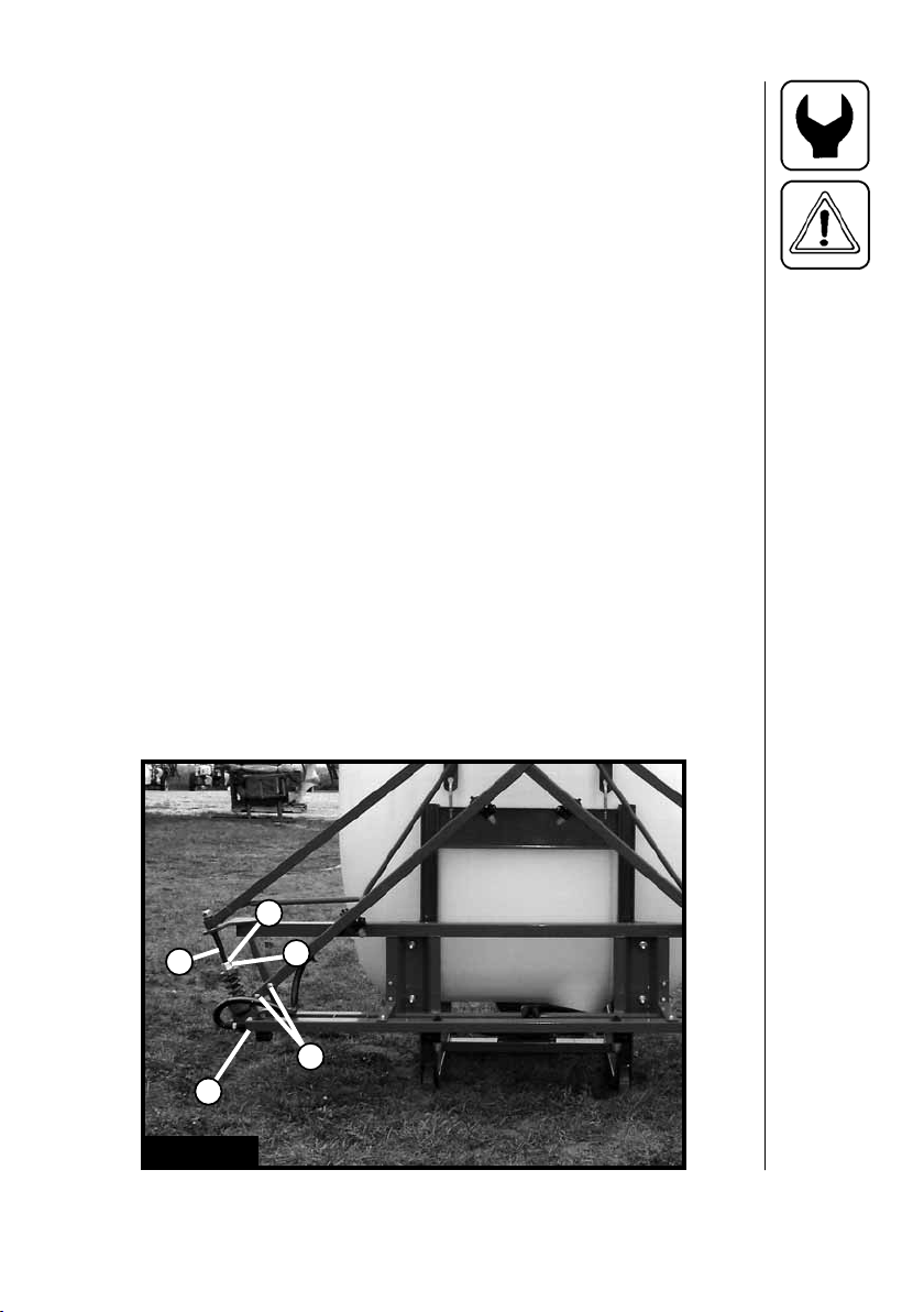
6.7 Breakaway Clutch Adjustment (MB Boom only)
WARNING: NEVER PLACE FINGERS INTO OPEN BREAKAWAY
CLUTCH OR YOU MAY BE INJURED SHOULD CLUTCH
SNAP CLOSED! DO NOT TIGHTEN THE BREAKAWAY
CLUTCH MORE THAN WHAT IS NECESSARY! OVER
TIGHTENING CAN CAUSE DAMAGE TO THE BOOM!
IMPORTANT: Properly lubricate clutch assembly before adjusting the
tension. Breakawa y clutch cap scre ws (A) (Fig. 29) must be torqued
to 40 Ft/lb (55 N-m) every week (40 hours) to prevent boom damage.
Lubricate every day (8 hours) to ensure maximum perf ormance and
life.
The tension on the clutch for the breakaway wing section can be
adjusted by loosening or tightening nut C (Fig. 29).
1. Check that the lower nut D (Fig. 29) is fully tightened.
2. The breakaway wing section should pivot around the axle shaft E
(Fig. 29). Make sure wing section is free to move.
3. Loosen jam nut B (Fig. 29).
4. If the breakaway clutch releases too easily, tighten nut C (Fig. 29).
If the breakaway clutch releases too stiffl y, loosen nut C (Fig. 29).
Clutch is properly tensioned when breakaway wing section returns
to alignment with center section after breaking away.
5. Tighten jam nut B (Fig. 29) after adjustment.
E
D
Fig. 29
B
C
A
57HARDI® N-SERIES 3-PT SPRAYER DIAPHRAGM OPERATOR'S MANUAL
Page 60

6.8 Lubrication
Recommended lubrication is shown in following tables.
Use ball bearing grease (lithium grease No. 2)
Note: If the sprayer is cleaned with a high pressure cleaner or fertilizer
has been used, we recommend lubrication of all sections.
Position on
sprayer
Oil
Sprayer Boom
2
Fig. 30
N-series sprayer lubrication points
Grease
Operation
hours
3
1
Page to find more
information
Winter protection
or off-season
storage
4
5
1. Pump
2. PTO
3. Agitation Control
4. MB Boom
5. Trapeze (40' MB only)
58 HARDI® N-SERIES 3-PT SPRAYER DIAPHRAGM OPERATOR'S MANUAL
Page 61

1X40
2
56
X
X
X
10
50
A
B
340
55
55
59HARDI® N-SERIES 3-PT SPRAYER DIAPHRAGM OPERATOR'S MANUAL
Page 62

48X57
58X
60 HARDI® N-SERIES 3-PT SPRAYER DIAPHRAGM OPERATOR'S MANUAL
Page 63

7.0 Off-Season Storage
When the spraying season is over, you should de vote some extra time
to the Spray er. If chem i cal res i dues are left over in the spray er for long
periods, it can reduce the life of the individual com po nents . To pre serve
the sprayer and pro tect the com po nents, carry out the following offsea son stor age pro gram:
1. Clean the sprayer completely - inside and outside - as described
under "Cleaning The Spray er" (section 6.1). Make sure that all
valves, hos es and auxiliary equipment have been cleaned with
de ter gent and fl ushed with clean wa ter afterwards, so no chem i cal
residues are left in the sprayer.
2. Replace any damaged seals and repair any leaks.
3. Empty the sprayer completely and let the pump work for a few
minutes. Operate all valves and handles to drain as much water
out of the spraying circuit as pos si ble. Let the pump run until air is
coming out of all the nozzles.
4. Pour in a mixture of ethylene glycol base antifreeze and water at the
ratio for the desired temperature protection (there will be a small
amount of water left in the hoses, pump and bottom of tank). The
volume of the mixture needs to be enough keep the tank sump full
while the pump is running fl uid through the entire circuit.
5. En gage the pump and op er ate all valves and func tions of the
plumbing system. Spray the spraygun (optional) into the tank until
antifreeze sprays out to make sure the line is full of antifreeze.
Open the distribution valves so the an ti freeze is sprayed through
the nozzles as well. The an ti freeze will also pre vent O-rings, seals,
di a phragms etc. from dry ing out.
6. When the sprayer is dry, re move rust from any scratch es or
damages in the paint and touch up the paint.
7. Lubricate all lubricating points according to the lu bri cat ing scheme
regardless of intervals stated.
8. Re move the glycerine-fi lled pres sure gaug e and store in a vertical
position in frost free con di tions.
9. Apply a thin layer of an ti cor ro sive oil (e.g. SHELL ENSIS FLU ID,
CASTROL RUSTILLO or sim i lar) on all metal parts. Avoid oil on
rubber parts, hoses and tires.
61HARDI® N-SERIES 3-PT SPRAYER DIAPHRAGM OPERATOR'S MANUAL
Page 64

Off-Season Storage (continued)
10. All electric plugs and sockets are to be stored in a dry plastic bag to
protect them from moisture, dirt, and corrosion.
11. Remove all the control boxes (including any rate controller control
box) from the tractor and store them in a dry and clean place.
12. To pro tect against dust, the spray er can be cov ered by a tar pau lin.
Ensure ventilation to prevent condensation.
7.1 Preparation After Off-Season Storage
After a stor age period, the sprayer should be pre pared for the next
season the fol low ing way:
1. Remove the cover. (If fi tted)
2. Fit the pressure gauge again. Seal with Tefl on tape.
3. Con nect the sprayer to the trac tor, including electric controls (if any).
4. Emp ty the tank of remaining an ti freeze.
5. Rinse the entire liquid circuit on the spray er with clean water.
6. Fill with clean water and check all functions.
62 HARDI® N-SERIES 3-PT SPRAYER DIAPHRAGM OPERATOR'S MANUAL
Page 65

8.0 ACCESSORIES
8.1 Clean Water Dispenser (optional)
Fig. 30
Fig. 31
Clean Water Dispenser
A handy source of fresh water on the sprayer to clean up plugged
nozzles and for rinsing gloves and hands after performing service or
maintenance.
8.2 Spraygun And Hose Wrap (optional)
Fig. 32
A spraygun with adjustable spray pattern and 25 ft. of 3/8" hose for
spraying fence row or spot spraying a small area can be installed onto
your sprayer. A handy hose wrap and spraygun holder can be conveniently located on the sprayer to transport the spraygun. A Hose Reel
with 160' of 3/8" hose* or 275' of 5/8" hose** is also available.
* Not available on N210 with boom
** Not available with boom
63HARDI® N-SERIES 3-PT SPRAYER DIAPHRAGM OPERATOR'S MANUAL
Page 66

8.3 Maverick Rate Controller (optional)
Fig. 33
The Maverick Rate Controller offers precise rate control regardless of
fi eld conditions. It is equipped with a Master control switch and built-in
boom switches. It features on-the-go rate adjustment, push button auto/
manual control for spot treatment, as well as a minimum fl ow feature to
ensure proper application pattern as ground speed slows to extremes.
8.4 Large 4" Pressure Gauge (optional)
Fig.33
Fig. 34
A large and easy to read 4" pressure gauge is available to replace the
standard 2-1/2" gauge.
64 HARDI® N-SERIES 3-PT SPRAYER DIAPHRAGM OPERATOR'S MANUAL
Page 67

8.5 Chemical Filler (optional)
Fig. 38
Fig. 35
Chemical Filler
Will inject all types of chemical formulations, liquid, powder or granules,
into the bottom of the tank near the agitation fl ow . A cleaning ring ensures
that chemical residue is removed from the fi ller tank.
8.6 Chemical Filler Bag & Bottle Rinse Kit (optional)
Fig. 39
Fig. 36
Chemical Filler Bag & Bottle Rinse Kit
A container rinse kit for liquid containers or plastic bags is also availab le
for installation into the chemical fi ller hopper.
65HARDI® N-SERIES 3-PT SPRAYER DIAPHRAGM OPERATOR'S MANUAL
Page 68

8.7 SMV Sign Kit (optional)
Fig.33
Fig. 37
A kit is available to mount an SMV Sign to the nozzle bracket.
66 HARDI® N-SERIES 3-PT SPRAYER DIAPHRAGM OPERATOR'S MANUAL
Page 69

9.0 TROUBLESHOO TING
9.1 General Spray Systems
Problem Cause
1. No liquid getting to the pump. A. Suction fi lter plugged.
2. Lack of pressure A. Suction fi lter plugged.
B. P.T.O. speed not fast enough.
C. Suction side air leak.
D. Pump valves obstructed
or worn. Replace valves if
necessary (Section 6.6).
E. Check pressure gauge.
3. Pressure jumping A. Suction side air leak.
B. P.T.O. shaft slipping on pump
crank shaft.
C. Suction fi lter partially plugged.
D. Check pressure gauge.
4. Pressure dropping A. P.T.O. shaft slipping on pump
crank shaft.
B. Suction side air leak.
C. Suction fi lter partially plugged.
5. Control box not operating one A. Check connections at battery.
or more boom sections B. Check for blown inline fuse on
power supply wiring harness.
(7.5 Amp - Section 3.3)
C. Check electrical wiring for bad
connection.
D. Check for 12 Volts at boom
distribution valve solenoids.
6. Liquid leaking from pump A. Damaged diaphragm(s).
Replace (Section 6.6).
7. Poor agitation A. Agitation valve not open.
B. Agitation nozzle plugged.
C. Agitation nozzle missing.
67HARDI® N-SERIES 3-PT SPRAYER DIAPHRAGM OPERATOR'S MANUAL
Page 70

9.1 General Spray Systems (continued)
Problem Cause
8. Excessive vibrations in hoses A. P.T.O. shaft slipping on pump
crank shaft.
B. Suction side air leak.
9. Can't get tank empty. A. Small tear or pin hole in
suction tube.
B. Tank is not level.
68 HARDI® N-SERIES 3-PT SPRAYER DIAPHRAGM OPERATOR'S MANUAL
Page 71

10.0 TECHNICAL SPECIFICA TIONS
10.1 Dimensions and weights
The following charts give approximate dimensions and weights for the
HARDI® N-series 3-PT sprayers. Since each sprayer can have many
different options/confi gurations, these are only approximate. If more
accurate results are needed, it is recommended to measure or weigh
the sprayer before connecting it to the tractor.
With boom Without boom
Tank
size
(Gal.)
105 55 x 75 x 83 375 1251 28 x 39 x 52 250 1126
155 55 x 101 x 102 475 1768 31 x 47 x 55 300 1593
210 55 x 101 x 102 525 2276 31 x 63 x 57 350 2101
Dimensions
a x b x c
(inches)
Empty
Weight
(lbs.)
Loaded
Weight*
(lbs.)
Dimensions
a x b x c
(inches)
Empty
Weight
(lbs.)
Loaded
Weight*
(lbs.)
*Total loaded weight with water. Some solutions may weigh more.
10.2 Power consumption
Minimum tractor requirements:
N105 ...................30HP (22 kW)
N155 ...................40HP (30 kW)
N210 ...................60HP (45 kW)
69HARDI® N-SERIES 3-PT SPRAYER DIAPHRAGM OPERATOR'S MANUAL
Page 72

11.0 WARRANTY POLICY AND CONDITIONS
HARDI® NORTH AMERICA INC. , 1500 West 76th Street, Davenport, Iowa, USA and 337 Sovereign Road,
London, Ontario, Canada hereinafter called “HARDI
the provisions below to each original retail purchaser of its own manufacturer, from an authorized HARDI®
dealer that such equipment is at the time of delivery to such purchaser, free from defects in material and
workmanship and that such equipment will be warranted for a period of one year from the time of delivery to
the end user, providing the machine is used and serviced in accordance with the recommendations in the
Operator’s Manual and is operated under normal farm conditions.
1. This limited warranty is subject to the following exceptions:
a) Parts of the machine not manufactured by HARDI
other components or trade accessories, etc.) are not covered by this warranty but are subject to the
warranty of the original manufacturer. Any claim falling into this category will be taken up with the
manufacturer concerned.
b) This warranty will be withdrawn if any equipment has been used for purposes other than for which it
was intended or if it has been misused, neglected, or damaged by accident, let out on hire or furnished
by a rental agency. Nor can claims be accepted if parts other than those manufactured by HARDI® have
been incorporated in any of our equipment. Further, HARDI® shall not be responsible for damage in
transit or handling by any common carrier and under no circumstances within or without the warranty
period will HARDI® be liable for damages of loss of use, or damages resulting from delay or any
consequential damage.
2. We cannot be held responsible for loss of livestock, loss of crops, loss because of delays in harvesting or
any other expense or loss incurred for labor, supplies, substitute machinery, rental for any other reason,
or for injuries either to the owner or to a third party, nor can we be called upon to be responsible for labor
charges, other than originally agreed, incurred in the removal or replacement of components.
3. The customer will be responsible for and bear the costs of:
a) Normal maintenance such as greasing, maintenance of oil levels, minor adjustments including the
boom.
b) Transportation of any HARDI® product to and from where the warranty work is to be performed.
c) Dealer travel time to and from the machine or to deliver and return the machine from the service
workshop for repair unless otherwise dictated by state law.
d) Dealer traveling costs.
4. Parts defi ned as normal wearing items, (i.e. Pump Diaphragms, Valves, O-rings, Tires and V-belts) are not
in any way covered under this warranty.
5. This warranty will not apply to any product which is altered or modifi ed without the express written
permission of the HARDI® Service and Engineering Departments and/or repaired by anyone other than
an Authorized HARDI® Dealer.
6. Warranty is dependent upon the strict observance by the purchaser of the following provisions:
a) That this warranty may not be assigned or transferred to anyone.
b) That the Warranty Registration Certifi cate has been correctly completed by dealer and purchaser with
their names and addresses, dated, signed and returned to the appropriate address as given on the
Warranty Registration Certifi cate within 30 days of delivery to the purchaser.
c) That all safety instructions in the operator's manual shall be followed and all safety guards regularly
inspected and replaced where necessary.
7. No warranty is given on second-hand products and none is implied.
®
”, offers the following limited warranty in accordance with
®
, (i.e. engines, tires, tubes, electronic controls and
70 HARDI® N-SERIES 3-PT SPRAYER DIAPHRAGM OPERATOR'S MANUAL
Page 73

WARRANTY POLICY AND CONDITIONS
8. Subject to the following terms, conditions and contributions, HARDI® extends the warranty on polyethylene
tanks (excluding fi ttings, lids and gaskets) to FIVE YEARS on fi eld sprayers and TEN YEARS on Orchard
and Vineyard sprayers. To qualify for this extended warranty, the tank must be drained and fl ushed with
fresh water after each day’s use. HARDI®’s liability is limited to replacement of defective parts FOB our
plants in Davenport, IA and London, Ontario, Canada at no cost to the purchaser for the fi rst twelve
months after date of purchase; at 20% of the then current retail price during the second year; at 40%
during the third year; at 60% during the fourth year; and at 80% during the fi fth year. This extended
warranty is subject, in each instance, to the tank being inspected and approved for replacement or repair
®
by HARDI
9. Subject to the following terms, conditions and contributions, HARDI® extends the warranty on HARDI®
diaphragm pumps (excluding wearing parts such as diaphragms, valves and o-rings) to FIVE YEARS. To
qualify for this extended warranty, the pump must be drained and fl ushed with fresh water after each day’s
use. HARDI®’s liability is limited to replacement of defective parts, FOB our plants in Davenport, IA and
London, Ontario, Canada at no cost to the to the purchaser during the fi rst twelve months after date of
purchase; at 20% of the then current retail price during the second year; at 40% during the third year; at
60% during the fourth year; and at 80% during the fi fth year. This fi ve year extended warranty is subject,
in each instance, to the pump being inspected and approved for replacement or repair by HARDI®
personnel before HARDI® will accept any liability hereunder.
10. HARDI® reserves the right to incorporate any change in design in its products without obligation to make
such changes on units previously manufactured.
11. The judgement of the HARDI® Service Department in all cases of claims under this warranty shall be fi nal
and conclusive and the purchaser agrees to accept its decisions on all questions as to defect and the
repair or exchange of any part or parts.
12. No employee or representative is authorized to change this warranty in any way or grant any other
warranty unless such change is made in writing and signed by the CEO in the Davenport offi ce. Approval
of warranty is the responsibility of the HARDI® Service Department.
13. Any warranty work performed which will exceed $1000.00 MUST be approved IN ADVANCE by the
Service Department. Warranty claims fi led without prior approval will be returned.
14. ANY pump replacement MUST be approved by the HARDI® Service Department.
15. Claims under this policy MUST be fi led with the HARDI® Service Department within thirty (30) days of
when the work is performed or warranty shall be void unless prior arrangements are made.
16. Parts which are requested for return by the HARDI® Service Department must be returned prepaid within
thirty (30) days for warranty settlement.
17. Warranty claims must be COMPLETELY fi lled out including part numbers and quantities or claims will be
returned to the submitting dealer.
DISCLAIMER OF FURTHER WARRANTY
THERE ARE NO WARRANTIES, EXPRESSED OR IMPLIED, EXCEPT AS SET FORTH ABOVE.
THERE ARE NO WARRANTIES WHICH EXTEND BEYOND THE DESCRIPTION OF THE PRODUCT
CONTAINED HEREIN. IN NO EVENT SHALL THE COMPANY BE LIABLE FOR INDIRECT, SPECIAL OR
CONSEQUENTIAL DAMAGES (SUCH AS LOSS OF ANTICIPATED PROFITS) IN CONNECTION WITH THE
RETAIL PURCHASER'S USE OF THE PRODUCT.
personnel before HARDI® will accept any liability hereunder.
71HARDI® N-SERIES 3-PT SPRAYER DIAPHRAGM OPERATOR'S MANUAL
Page 74

12.0 NOTES
72 HARDI® N-SERIES 3-PT SPRAYER DIAPHRAGM OPERATOR'S MANUAL
Page 75

Page 76

For Product, Service or Warranty Information:
- Please contact your local HARDI® dealer.
To contact HARDI® directly:
- Please use the HARDI® Customer Service number: 1-866-770-7063
- Or send your email to: CUSTSERV@hardi-us.com
Visit us online at: www.hardi-us.com
HARDI® NORTH AMERICA INC.
1500 West 76th St.
Davenport, Iowa 52806
Phone: (563) 386-1730
Fax: (563) 386-1710
337 Sovereign Rd.
London, Ontario N6M 1A6
Phone: (519) 659-2771
Fax: (519) 659-2821
 Loading...